EP1833302B1 - Method and system for scalding slaughtered poultry - Google Patents
Method and system for scalding slaughtered poultry Download PDFInfo
- Publication number
- EP1833302B1 EP1833302B1 EP05777812A EP05777812A EP1833302B1 EP 1833302 B1 EP1833302 B1 EP 1833302B1 EP 05777812 A EP05777812 A EP 05777812A EP 05777812 A EP05777812 A EP 05777812A EP 1833302 B1 EP1833302 B1 EP 1833302B1
- Authority
- EP
- European Patent Office
- Prior art keywords
- scalding
- poultry
- nozzles
- zones
- succeeding
- Prior art date
- Legal status (The legal status is an assumption and is not a legal conclusion. Google has not performed a legal analysis and makes no representation as to the accuracy of the status listed.)
- Expired - Lifetime
Links
Images



Classifications
-
- A—HUMAN NECESSITIES
- A22—BUTCHERING; MEAT TREATMENT; PROCESSING POULTRY OR FISH
- A22C—PROCESSING MEAT, POULTRY, OR FISH
- A22C21/00—Processing poultry
- A22C21/04—Scalding, singeing, waxing, or dewaxing poultry
Definitions
- the method according to the invention is characterised in that in a first scalding zone hot water is used as scalding agent, that in succeeding scalding zones scalding agents with mutually differing temperatures are applied, that in the said succeeding scalding zones warm humid air is used as scalding agent which is at least blown onto specific sub areas of the poultry, and that the poultry is then conveyed between additional rows of nozzles in an additional scalding zone where warm humid air is blown at least on the remaining sub areas of the poultry.
- the poultry during its passage through the scalding tunnel is turned relative to the direction of conveying, that is so that the wings of the poultry are angularly turned in relation to the direction of transport.
- the poultry may hang closer without the wings coming into mutual contact.
- the capacity of a scalding tunnel may be increased by angular turning of the wings of the poultry, as the mutual hanger spacing may be reduced thereby.
- due to risk of infection individual poultry must not come into direct contact with other poultry during the passage of the scalding tunnel.
- the apparatus or scalding tunnel 10 includes, as it appears from Figs. 3 and 4 , centrifugal blowers 14 which are built into the ceiling of the scalding tunnel 10, that is which have horizontal ventilator wings driven by vertically disposed motors 16, which is different from the prior art scalding chambers or scalding tunnels 2 shown in Figs. 1 and 2 , where centrifugal blowers 5 are mounted separately upon the scalding chamber or the scalding tunnel 2.
Landscapes
- Life Sciences & Earth Sciences (AREA)
- Engineering & Computer Science (AREA)
- Wood Science & Technology (AREA)
- Zoology (AREA)
- Food Science & Technology (AREA)
- Processing Of Meat And Fish (AREA)
- Agricultural Chemicals And Associated Chemicals (AREA)
- Catching Or Destruction (AREA)
Abstract
Description
- The present invention concerns a method for scalding slaughtered poultry, by way of example chickens, turkeys, ducks and geese, and of the kind specified in the preamble of
claim 1. - The invention also concerns an apparatus for scalding slaughtered poultry according to the method according to the invention.
- In order to scald slaughtered poultry prior to plucking with regard to facilitating the subsequent plucking, it is prior art to convey poultry suspended at the feet through an elongated tank with hot water, possibly combined with injecting air in the scalding vessel through lower nozzles.
- By a second prior art method, the poultry is transported successively and suspended at the feet in a conveyor via an inlet sluice through a closed scalding chamber, in which the atmosphere is heated by means of vapour-saturated air which is injected into the chamber and directly upon the poultry. The advantages of applying vapour-saturated air are significant energy savings and a very substantial reduction in dissemination of bacteria, as the poultry are not submerged in a water bath and do not come into direct mutual contact.
- Besides, an improved working climate is achieved in the surrounding plucking room as a consequence of a much reduced production of vapour. The poultry is to stay a certain time in the closed scalding chamber, determined by the length and the course of the conveyor belt in the scalding chamber and of its capacity and/or speed. In order to utilise the space in the scalding chamber optimally, the conveyor belt runs in parallel tracks back and forth inside the scalding chamber in the same or at plural levels.
-
EP-A1-1 297 748 discloses a method and an apparatus for scalding poultry where, by means of a primary system of nozzles at the bottom of the scalding chamber, saturated steam is injected which is used for producing humid hot air that is sucked out at the top in the scalding chamber and re-injected directly upon the poultry by means of a secondary system of nozzles. Even if saturated steam is used for heating the scalding air, by this method it is possible anyway to work with a low scalding temperature of about 50°C or with a higher scalding temperature of about 60°C, as the poultry is not at any time subjected to the direct action of saturated steam. -
WO-A1-03/088751 -
US-A-3 748 691 discloses an apparatus for treating animal carcasses, and more particular to a system for treating fowl such as poultry to destroy surface bacteria and to loosen the feather thereof to facilitate subsequent defeathering. An enclosed housing is provided through which fowl may be carried along a predetermined path. A conveyor is supported in the housing to define the predetermined path and carries shackles for suspending the fowl in spaced relationship there along. Spray nozzles extend along the housing on opposite side of the predetermined path and direct a high temperature spray medium against the fowl in order to loosen the feather thereof and also to destroy the bacteria carried by the fowl. Structure is provided for constraining the movement of the shackles such that the back areas of the fowl are maintained in a preselected position along the predetermined path in order to receive maximum amounts of the high temperature spray medium. -
GB-1 075 390 - On that background, it is the purpose of the invention to indicate a further improved method and a further improved system for scalding slaughtered poultry of the kind specified in the preambles of
claim 1 and 3, respectively, and which enable further optimisation of the scalding with the intention of achieving subsequent optimal plucking, to avoid unnecessary heat action on the poultry and to attain further reduction of the energy consumption. - The method according to the invention is characterised in that in a first scalding zone hot water is used as scalding agent, that in succeeding scalding zones scalding agents with mutually differing temperatures are applied, that in the said succeeding scalding zones warm humid air is used as scalding agent which is at least blown onto specific sub areas of the poultry, and that the poultry is then conveyed between additional rows of nozzles in an additional scalding zone where warm humid air is blown at least on the remaining sub areas of the poultry.
- In a simple way is hereby achieved possibility of further optimising the scalding, so that optimal plucking may occur subsequently without the poultry subjected to unnecessary heat action, and so that a considerable reduction of the required energy consumption is attained simultaneously. Furthermore is achieved that the sub areas of the poultry, which are the most easy to pluck the feathers from, are also treated most gently by minimising the harmful heat action on respective sub areas of the poultry.
- With the purpose of achieving the best possible effect of the humid, hot air, it is of great significance that temperature, pressure and amount of scalding agent are correctly adjusted for scalding the said specific sub areas of the poultry, so that softening of follicles and the subsequent plucking of feathers from the said specific sub areas of the poultry are also optimised. It is furthermore advantageous that in a first scalding zone, hot water is used to preheat and flush the feathers of the poultry free from dust and fat, so that the follicles may be softened more efficiently by applying scalding agent in the form of warm humid air in the succeeding scalding zones.
- The most difficult sub areas on the poultry are - when speaking of plucking feathers - the tail region and top sides of wings, why these areas are to be applied the greatest amount of scalding agent in the form of warm humid air at the highest temperature. On other sub areas of the poultry, it is considerably easier to pluck off the feathers, i.e. follicles in these sub areas do not require so intensive softening. In other words, very substantial amounts of energy may be saved by controlling and optimising the supply and the temperature of the scalding agent to respective sub areas of the poultry.
- It is to be mentioned that it may be advantageous that the poultry during its passage through the scalding tunnel is turned relative to the direction of conveying, that is so that the wings of the poultry are angularly turned in relation to the direction of transport. Hereby may be achieved that the poultry may hang closer without the wings coming into mutual contact. In other words, the capacity of a scalding tunnel may be increased by angular turning of the wings of the poultry, as the mutual hanger spacing may be reduced thereby. In this connection it is important to point out that due to risk of infection, individual poultry must not come into direct contact with other poultry during the passage of the scalding tunnel.
- The method according to the invention is most suitably further modified in that after passing through the first-mentioned row of nozzles, the poultry is passed through a primary plucking station, where feathers are plucked from the first-mentioned specific sub-areas of the poultry, and that the poultry, after passing through the additional rows of nozzles, is passed through a secondary plucking station where the remaining feathers are plucked from the poultry.
- The invention also concerns an apparatus for use in the method according to the invention and including a largely closed scalding tunnel with a conveyor that runs past a system of nozzles which are arranged to apply scalding agent on the poultry, the apparatus being characterised in that the scalding tunnel includes a first scalding zone with rows of nozzles that are adapted to spray hot water on the poultry, and succeeding scalding zones which are adapted to work with different temperatures of the scalding agent, and which are designed with a system of nozzles that are arranged for blowing warm humid air on specific sub areas of the poultry.
- The apparatus according to the invention is suitably designed so that the temperature of the scalding agent in a first of succeeding scalding zones is about 60°C, and that the temperature of the scalding agent in a second of the succeeding scalding zones is about 50°C.
- With the intention of minimising the required heat action on the poultry and for the best possible utilisation of the gentle, though purposeful softening of the specific sub areas of the poultry, the apparatus according to the invention may advantageously be designed so that after the first of the succeeding scalding zones, it includes a first plucking station which is adapted for plucking feathers from the first-mentioned specific sub areas of the poultry.
- With the purpose of optimising also the plucking of feathers from the remaining sub areas of the poultry, the apparatus according to the invention may advantageously be designed so that after the second of the said succeeding scalding zones, it includes a second plucking station which is adapted for plucking the remaining feathers from the poultry.
- With the intention of optimising supply of the scalding agent to specific sub areas of the poultry, the apparatus according to the invention may suitably be designed so that the system of nozzles includes movable and individually controllable nozzles which are adapted to follow the poultry at least over a sub-distance of the scalding zones.
- The apparatus according to the invention may furthermore advantageously be designed so that the movable nozzles are designed in elongated cylindrical drums that are rotated about a horizontal axis, so that preferably helical discharge openings of the nozzles are moved along the poultry in the direction of conveying of the latter.
- As a supplement, the apparatus according to the invention may furthermore be designed so that the individually controllable nozzles are designed in elongated cylindrical drums which are rotated about an inclining axis, so that preferably helical discharge openings of the nozzles are moved in vertical direction as well as in horizontal direction relative to the direction of conveying of the poultry.
- The invention is explained more closely in the following with reference to the drawing, on which:
- Fig. 1
- shows a vertical section through a scalding chamber known from the above mentioned
EP-A1-1 297 748 ; - Fig. 2
- shows a horizontal side view and a vertical section through a second scalding chamber known from the above mentioned
WO 03/088751 - Fig. 3
- shows a longitudinal section through an embodiment of a scalding tunnel according to the invention;
- Fig. 4
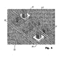
- shows an elementary sketch in perspective view of an embodiment of a blower arrangement with common manifold for distributing the humid warm scalding air to several nozzle sections of a scalding tunnel according to the invention;
- Fig. 5
- shows a elementary sketch of in perspective view of an embodiment of a nozzle arrangement with two rotating elongated helical discharge or nozzle opening according to the invention;
- Fig. 6
- shows an embodiment of a flow diagram of a primary steam system by a scalding tunnel according of the invention;
- Fig. 7
- shows an embodiment of a flow diagram for a secondary steam system according to the invention;
- Fig. 8
- shows an embodiment of a flow diagram of a manifold system for controlling and distributing the scalding means in the form of humid warm air for a scalding tunnel according to the invention;
- Fig. 9
- shows an embodiment of a flow diagram for a primary and a secondary water distributing system for a scalding tunnel according to the invention;
- Fig. 10
- shows two views of an alternative embodiment of elongated pivotable slotted nozzles for controlled application of scalding agent to specific sub areas of the poultry, e.g. the tail region, during its passage through a scalding tunnel according to the invention; and
- Fig. 11
- shows a horizontal section through a preferred embodiment of a scalding tunnel according to the invention; and
- Fig. 12
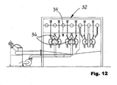
- shows a vertical section through the preferred scalding tunnel shown in
Fig. 11 . - The apparatus or scalding
tunnel 10 according to the invention includes, as it appears fromFigs. 3 and4 ,centrifugal blowers 14 which are built into the ceiling of the scaldingtunnel 10, that is which have horizontal ventilator wings driven by vertically disposedmotors 16, which is different from the prior art scalding chambers orscalding tunnels 2 shown inFigs. 1 and 2 , wherecentrifugal blowers 5 are mounted separately upon the scalding chamber or thescalding tunnel 2. - The apparatus or the scalding
tunnel 10 according to the invention also uses the same heating principle for the scalding agent, which is shown inFigs. 1 and 2 , as the scalding means in the form of warm humid air is produced by injecting vapour-saturated steam in a lower part of the scaldingtunnel 10 by means of a primary system of nozzles. Subsequently, the warm humid scalding air is evacuated by means of thecentrifugal blowers 14 which then re-inject the scalding air directly onto the poultry which passes through the scaldingtunnel 10 suspended by the legs by means of hangers in aconveyor track 12. - The
conveyor 12 runs through a firstscalding section 16 of the scaldingtunnel 10 shown inFig. 3 in three mutuallyparallel tracks 18 that run between a system of nozzles arranged to blow warm humid air directly on specific sub areas of the poultry before it is conveyed through aprimary plucking station 20, where feathers are plucked off from at least the said specific sub areas of the poultry. These sub areas may e.g. consist of the tail region of the poultry and top sides of wings, where follicles are most difficult to soften with the object of mechanised plucking of feathers. Then the poultry is continued on theconveyor track 12 through a secondscalding section 22 in which the poultry, also in mutually parallel tracks, passes between a second system of nozzles which are arranged to blow warm humid air on the remaining parts of the poultry, which then passes yet a plucking station (not shown) where the remaining feathers are plucked by machine. -
Fig. 4 shows how thecentrifugal blowers 14 are built into the ceiling of the scaldingtunnel 10, and how fourcentrifugal blowers 14 via acommon manifold 24 supply a very large number of not shown injection nozzles. -
Fig. 5 shows an embodiment of aspecial nozzle arrangement 26 with two rotating elongatedcylindrical drums 28 with helical discharge ornozzle openings 30. According to need, thenozzle arrangement 26 may be mounted horizontally in relation to the direction of movement of the poultry through the scaldingtunnel 10, i.e. so that the discharge ornozzle openings 30 follow the poultry by rotating thedrums 28 and blows scalding agent upon the poultry over a length determined by the length of thenozzle arrangement 26. - Alternatively, the
nozzle arrangement 26 may be mounted at an oblique angle in relation to the vertical or the horizontal so that thenozzle opening 30 may be moved both in horizontal and in vertical direction compared with the direction of movement of the poultry during its passage past thenozzle arrangement 26. -
Fig. 6 shows a flow diagram for the primary steam system, where steam is let in at B0.00 and passes a filter B2.00, a flow meter (steam volume) OB3.00. Downwards, a condensate separator B9.00 is arranged. The primary steam flow passes a pressure control valve B5.00, where after the steam is divided into two main streams with each their motor-operated valve B8.00/Z8.00, from where the steam is conducted to each their nozzle group B15.00/Z15.00 which is also shown in Fig. Between the pressure control valve B5.00 and a T-branch to the motor-operated valve B8.00/Z8.00 there is provided a branch from the primary steam flow, so that high-pressure steam may be conducted to respective tunnel sections with the purpose of controlling the temperature of the scalding agent via branches B13.00/Z13.00, as well as steam may be drawn off via a separate branch B14.00 for optional separate scalding of the feet of the poultry. -
Fig. 8 shows a flow diagram for two manifold systems for distributing controlled scalding agent in the form of warm humid air to each their section B and Z of scaldingtunnel 10, where admixing of extra water via the valve groups B25.00/Z25.00 (Fig. 9 ) and each their hose branch may be effected directly down into the tangentially arranged discharge pipes which are directly connected with the injecting nozzles, and which each additionally comprise the motor-operated valves B31.00-31.07/Z31.00-31.07 that are each controlled via control wires from common terminal strips B30.00/Z30.00 (only the control wires from terminal strip B30.00 to B31.00-31.07 are shown at the bottom ofFig. 8 ). - B40.00/Z40.00 are temperature sensors that measure the temperature in respective sections of scalding
tunnel 10. B41.00/Z41.00 are temperature sensors showing the actual temperatures of scalding agent, while B42.00/Z42.00 are humidity sensors showing the actual humidity of the scalding agent. -
Fig. 9 shows an embodiment of a flow diagram of a primary and secondary water distribution system, where B20.02 is a water pump supplying water at 4-8 bar, where B22.00/Z22.00 are solenoid valves for each their group B24.00/Z24.00 of water atomising nozzles for respective sections of scaldingtunnel 10. The water atomising nozzles are disposed on the tunnel wall above the steam nozzles and serve to regulate the actual humidity of the warm scalding air. -
Fig. 10 shows two views of an alternative embodiment of elongated pivotable slotted nozzles for controlled supply of scalding agent to specific sub areas of the poultry, e.g. its tail region, during its passage through a scalding tunnel according to the invention. - The preferred embodiment of a scalding
tunnel 32 shown inFigs. 11 and12 includes a first scaldingzone 34 provided with a system ofnozzles 36 which is adapted to spray hot water (52-60°C) on the poultry with the intention of preheating and flushing the plumage free from dust and fat so that the softening of the follicles of the poultry becomes more efficient in the succeeding scalding zones, where warm humid air is used for softening follicles of specific sub areas of the poultry. - With the intention of optimising energy saving, the warm flushing water is collected at the bottom of the scalding
tunnel 32, so that it may be reused together with the condensate from the subsequent nozzles supplying warm humid air on specific sub areas of the poultry. - In that connection, it is important to point out that no risk of infection occurs by using and reusing warm water for spraying on the poultry, as this occurs before the plucking, i.e. before follicles are exposed.
Claims (9)
- A method for scalding slaughtered poultry, by way of example chickens, turkeys, ducks or geese, where the poultry is transported through a scalding tunnel after slaughtering suspended at the feet, where the poultry in the scalding tunnel is conveyed successively between rows of nozzles that are adapted to apply scalding agent to the poultry, where a plurality of different scalding agents are applied, wherein in a first scalding zone hot water is used as scalding agent, characterised in that in succeeding scalding zones scalding agents with mutually differing temperatures are applied, that in the said succeeding scalding zones warm humid air is used as scalding agent which is blown onto specific sub areas of the poultry, and that the poultry is then conveyed between additional rows of nozzles in an additional scalding zone where warm humid air is blown on the remaining sub areas of the poultry.
- Method according to claim 1, characterised in that after passing through the first-mentioned scalding zones, the poultry is passed through a primary plucking station, where feathers are plucked from the first-mentioned specific sub-areas of the poultry, and that the poultry, after passing through the additional scalding zone, is passed through a secondary plucking station where the remaining feathers are plucked from the poultry.
- An apparatus for use in the method according to claim 1 and including a largely closed scalding tunnel (10) with a conveyor that runs past a system of nozzles which are arranged to apply scalding agent on the poultry, characterised in that the scalding tunnel includes a first scalding zone (16) with rows of nozzles that are adapted to spray hot water on the poultry, and succeeding scalding zones which are adapted to work with different temperatures of the scalding agent, and which are designed with a system of nozzles that are arranged for blowing warm humid air on specific sub areas of the poultry.
- Apparatus according to claim 3, characterised in that the temperature of the scalding agent in a first of succeeding scalding zones is about 60°C, and that the temperature of the scalding agent in a second of the succeeding scalding zones is about 50°C.
- Apparatus according to claims 3-4, characterised in that after the first of the succeeding scalding zones, it includes a first plucking station (20) which is adapted for plucking feathers from the first-mentioned specific sub areas of the poultry.
- Apparatus according to claims 3-4, characterised in that after the second of the said succeeding scalding zones, it includes a second plucking station which is adapted for plucking the remaining feathers from the poultry.
- Apparatus according to claims 3-6, characterised in that the system of nozzles in the succeeding scalding zones includes movable and individually controllable nozzles which are adapted to follow the poultry at least over a sub-distance of the scalding zones.
- Apparatus according to claims 3-7, characterised in that movable nozzles are designed in elongated cylindric drums (28) that are rotated about a horizontal axis, so that the discharge openings of the nozzles are moved along the poultry in the direction of conveying of the latter.
- Apparatus according to claims 3-7, characterised in that individually controllable nozzles are designed in elongated cylindric drums which are rotated about an inclining axis, so that the discharge openings of the nozzles are moved in vertical direction as well as in horizontal direction relative to the direction of conveying of the poultry.
Applications Claiming Priority (2)
| Application Number | Priority Date | Filing Date | Title |
|---|---|---|---|
| DKPA200401334 | 2004-09-03 | ||
| PCT/DK2005/000566 WO2006024305A1 (en) | 2004-09-03 | 2005-09-05 | Method and system for scalding slaughtered poultry |
Publications (2)
| Publication Number | Publication Date |
|---|---|
| EP1833302A1 EP1833302A1 (en) | 2007-09-19 |
| EP1833302B1 true EP1833302B1 (en) | 2010-01-27 |
Family
ID=35999722
Family Applications (1)
| Application Number | Title | Priority Date | Filing Date |
|---|---|---|---|
| EP05777812A Expired - Lifetime EP1833302B1 (en) | 2004-09-03 | 2005-09-05 | Method and system for scalding slaughtered poultry |
Country Status (8)
| Country | Link |
|---|---|
| US (1) | US8066556B2 (en) |
| EP (1) | EP1833302B1 (en) |
| AT (1) | ATE456305T1 (en) |
| BR (1) | BRPI0514912B1 (en) |
| DE (1) | DE602005019206D1 (en) |
| DK (1) | DK1833302T3 (en) |
| ES (1) | ES2339785T3 (en) |
| WO (1) | WO2006024305A1 (en) |
Families Citing this family (9)
| Publication number | Priority date | Publication date | Assignee | Title |
|---|---|---|---|---|
| DE202007001643U1 (en) * | 2007-01-31 | 2007-06-06 | Banss Schlacht- und Fördertechnik GmbH | Steaming tunnel for slaughtered animals especially pigs uses steam and water sprays and has doors to separate tunnel into sections having different temperatures |
| NL2002250C2 (en) * | 2008-11-25 | 2010-05-26 | Stork Pmt | DEVICE AND METHOD FOR GROWING A LARGE INTENSITY OF DIFFERENT PARTS OF A POULTRY CARCASE. |
| US8827775B2 (en) * | 2011-10-26 | 2014-09-09 | Wayne Allen Jefferson, SR. | Device for removing material from feet of poultry |
| GB201421501D0 (en) * | 2014-12-03 | 2015-01-14 | Moy Park Ltd | Apparatus and method for improving the hygiene of poultry processing |
| DE102015104652B3 (en) * | 2015-03-26 | 2016-02-25 | Linco Food Systems A/S | Apparatus and method for brewing slaughtered poultry |
| CN114929023B (en) * | 2020-03-06 | 2023-04-28 | 丹麦巴德尔食品系统公司 | Apparatus and method for scalding slaughtered poultry |
| CN111631249A (en) * | 2020-06-16 | 2020-09-08 | 张婷婷 | Slaughtering scalding machine capable of reducing chicken feather residue |
| US11439155B1 (en) * | 2021-04-07 | 2022-09-13 | Danny Johnsrud | Fish descaling assembly |
| CN115067377B (en) * | 2022-06-27 | 2023-03-24 | 东莞增米中央厨房供应链有限公司 | Energy-saving poultry scalding machine |
Family Cites Families (33)
| Publication number | Priority date | Publication date | Assignee | Title |
|---|---|---|---|---|
| US2830318A (en) * | 1954-02-23 | 1958-04-15 | Gordon Johnson Equipment Compa | Method of processing poultry |
| US3074103A (en) * | 1960-04-11 | 1963-01-22 | Karl M Roth | Fowl defeathering method |
| GB1075390A (en) | 1965-11-29 | 1967-07-12 | Gainesville Machine Co Inc | Apparatus for and method of scalding fowl at multiple temperatures |
| US3561040A (en) * | 1968-08-02 | 1971-02-09 | Food Equipment Inc | Spraying apparatus and method for use in conjunction with fowl defeathering apparatus |
| US3748691A (en) * | 1969-06-10 | 1973-07-31 | Fei Inc Dallas | Vaporizing apparatus for treatment of animal carcasses |
| US3703744A (en) * | 1971-01-13 | 1972-11-28 | Food Equipment Inc | Fowl singeing system |
| US3744088A (en) * | 1971-03-22 | 1973-07-10 | Fei Inc | Vaporizing apparatus for treatment of animal carcasses |
| US3729773A (en) * | 1971-11-26 | 1973-05-01 | Fei Inc | Method for washing and chilling eviscerated fowl |
| US4196221A (en) * | 1977-06-10 | 1980-04-01 | Dew Denise R | Method and equipment for processing food products |
| US4388811A (en) * | 1981-09-22 | 1983-06-21 | Meyn U.S.A., Inc. | Method for preparing poultry for fresh-pack handling |
| US4862557A (en) * | 1987-01-16 | 1989-09-05 | Monfort Of Colorado, Inc. | Animal slaughtering chemical treatment and method |
| GB8714898D0 (en) | 1987-06-25 | 1987-07-29 | Du Pont Canada | Protecting articles from bleaching solutions |
| US4868950A (en) * | 1989-01-03 | 1989-09-26 | Centennial Machine Company, Inc. | Fowl scalding apparatus and method |
| DK165866C (en) | 1989-01-31 | 1993-06-28 | Slagteriernes Forskningsinst | PROCEDURE FOR SHOULDING THE CARCASSES AND APPARATUS FOR EXERCISING THE PROCEDURE |
| US4944068A (en) * | 1989-10-27 | 1990-07-31 | Covell Iii Edward H | Poultry scalder, scalding system and process |
| US4947518A (en) * | 1989-10-11 | 1990-08-14 | Covell Iii Edward H | Poultry scalding system and process |
| US4852215A (en) * | 1989-02-27 | 1989-08-01 | Covell Iii Edward H | Poultry scalding system and process |
| US4961248A (en) * | 1990-01-19 | 1990-10-09 | Johnson Food Equipment, Inc. | Scalder apparatus |
| US4996741A (en) * | 1990-07-27 | 1991-03-05 | Covell Iii Edward H | Poultry washing and scalding system and process |
| US5405289A (en) * | 1991-06-10 | 1995-04-11 | T. Thomas Metier | Method for slaughtering and removing the hide from ratites, including ostrich and emu |
| US5485332A (en) * | 1992-11-30 | 1996-01-16 | Minebea Co., Ltd. | Floating magnetic head having a chamfered magnetic head core |
| US5899802A (en) * | 1994-03-14 | 1999-05-04 | Burnett; Bertram B. | Tenderizing poultry meat through constant electrical stimulation |
| US5439694A (en) * | 1994-07-11 | 1995-08-08 | Morris & Associates, Inc. | Poultry preparation process and apparatus |
| US5882253A (en) * | 1997-12-12 | 1999-03-16 | Rhodia, Inc. | Apparatus and method for cleaning poultry |
| US6605308B2 (en) * | 2001-01-16 | 2003-08-12 | Tomoco2 Equipment Company | Pathogen management system |
| DE10148568A1 (en) | 2001-10-01 | 2003-04-24 | Bernhard Wichelmann | Method and device for preparing slaughtered poultry for plucking |
| NL1019298C2 (en) * | 2001-11-05 | 2003-05-07 | Stork Pmt | Method for preserving meat from a slaughtered bird or part thereof. |
| EP1460902B1 (en) * | 2001-11-30 | 2007-10-31 | C & C Systems Limited | Carcass processing apparatus |
| US6749497B2 (en) * | 2002-04-04 | 2004-06-15 | Tyson Foods, Inc. | Apparatus and method of edible feet harvest and paw production |
| AU2003226950A1 (en) | 2002-04-19 | 2003-11-03 | Linco Food Systems A/S | A method and an apparatus for scalding slaughtered poultry |
| US6733379B2 (en) * | 2002-07-10 | 2004-05-11 | Rhodia Inc. | Post-evisceration process and apparatus |
| US6918825B2 (en) * | 2003-08-26 | 2005-07-19 | Everett T. Conaway | Poultry de-feathering apparatus and method |
| US7189157B2 (en) * | 2003-11-05 | 2007-03-13 | Linco Food Systems A/S | Method and a device for the preparation of slaughtered poultry for picking |
-
2005
- 2005-09-05 ES ES05777812T patent/ES2339785T3/en not_active Expired - Lifetime
- 2005-09-05 EP EP05777812A patent/EP1833302B1/en not_active Expired - Lifetime
- 2005-09-05 AT AT05777812T patent/ATE456305T1/en not_active IP Right Cessation
- 2005-09-05 BR BRPI0514912-6A patent/BRPI0514912B1/en active IP Right Grant
- 2005-09-05 DK DK05777812.8T patent/DK1833302T3/en active
- 2005-09-05 DE DE602005019206T patent/DE602005019206D1/en not_active Expired - Lifetime
- 2005-09-05 US US11/574,707 patent/US8066556B2/en active Active
- 2005-09-05 WO PCT/DK2005/000566 patent/WO2006024305A1/en not_active Ceased
Also Published As
| Publication number | Publication date |
|---|---|
| DE602005019206D1 (en) | 2010-03-18 |
| DK1833302T3 (en) | 2010-05-03 |
| BRPI0514912A (en) | 2008-06-24 |
| ATE456305T1 (en) | 2010-02-15 |
| ES2339785T3 (en) | 2010-05-25 |
| US20090042496A1 (en) | 2009-02-12 |
| BRPI0514912B1 (en) | 2014-12-09 |
| WO2006024305A1 (en) | 2006-03-09 |
| EP1833302A1 (en) | 2007-09-19 |
| US8066556B2 (en) | 2011-11-29 |
Similar Documents
| Publication | Publication Date | Title |
|---|---|---|
| EP2046132B2 (en) | Device for scalding poultry | |
| US3657768A (en) | Vaporizing technique for treatment of animal carcasses | |
| JP5908727B2 (en) | Apparatus and method for heat-treating different body parts of poultry carcasses with different strengths | |
| CN104968205A (en) | A tunnel | |
| US4947518A (en) | Poultry scalding system and process | |
| US8066556B2 (en) | Method and system for scalding slaughtered poultry | |
| CN110604165B (en) | Poultry slaughtering system | |
| US4944068A (en) | Poultry scalder, scalding system and process | |
| US3748691A (en) | Vaporizing apparatus for treatment of animal carcasses | |
| US10064415B2 (en) | Device and method for scalding slaughtered poultry | |
| EP1496750B1 (en) | A method and an apparatus for scalding slaughtered poultry | |
| US7950986B2 (en) | Carcass processing apparatus | |
| US7207879B2 (en) | Carcass processing apparatus | |
| CN219479067U (en) | Pig slaughtering system | |
| US3138822A (en) | Poultry processing method and apparatus | |
| GB2394643A (en) | Treating carcasses with hot air | |
| CN116172037A (en) | A pig slaughtering system | |
| WO2024231552A1 (en) | A method of chilling poultry carcasses and a chilling system |
Legal Events
| Date | Code | Title | Description |
|---|---|---|---|
| PUAI | Public reference made under article 153(3) epc to a published international application that has entered the european phase |
Free format text: ORIGINAL CODE: 0009012 |
|
| 17P | Request for examination filed |
Effective date: 20070320 |
|
| AK | Designated contracting states |
Kind code of ref document: A1 Designated state(s): AT BE BG CH CY CZ DE DK EE ES FI FR GB GR HU IE IS IT LI LT LU LV MC NL PL PT RO SE SI SK TR |
|
| DAX | Request for extension of the european patent (deleted) | ||
| 17Q | First examination report despatched |
Effective date: 20090417 |
|
| GRAP | Despatch of communication of intention to grant a patent |
Free format text: ORIGINAL CODE: EPIDOSNIGR1 |
|
| GRAS | Grant fee paid |
Free format text: ORIGINAL CODE: EPIDOSNIGR3 |
|
| GRAA | (expected) grant |
Free format text: ORIGINAL CODE: 0009210 |
|
| AK | Designated contracting states |
Kind code of ref document: B1 Designated state(s): AT BE BG CH CY CZ DE DK EE ES FI FR GB GR HU IE IS IT LI LT LU LV MC NL PL PT RO SE SI SK TR |
|
| REG | Reference to a national code |
Ref country code: GB Ref legal event code: FG4D |
|
| REG | Reference to a national code |
Ref country code: CH Ref legal event code: EP |
|
| REG | Reference to a national code |
Ref country code: IE Ref legal event code: FG4D |
|
| REF | Corresponds to: |
Ref document number: 602005019206 Country of ref document: DE Date of ref document: 20100318 Kind code of ref document: P |
|
| REG | Reference to a national code |
Ref country code: DK Ref legal event code: T3 |
|
| REG | Reference to a national code |
Ref country code: NL Ref legal event code: T3 |
|
| REG | Reference to a national code |
Ref country code: ES Ref legal event code: FG2A Ref document number: 2339785 Country of ref document: ES Kind code of ref document: T3 |
|
| LTIE | Lt: invalidation of european patent or patent extension |
Effective date: 20100127 |
|
| PG25 | Lapsed in a contracting state [announced via postgrant information from national office to epo] |
Ref country code: AT Free format text: LAPSE BECAUSE OF FAILURE TO SUBMIT A TRANSLATION OF THE DESCRIPTION OR TO PAY THE FEE WITHIN THE PRESCRIBED TIME-LIMIT Effective date: 20100127 |
|
| PG25 | Lapsed in a contracting state [announced via postgrant information from national office to epo] |
Ref country code: IS Free format text: LAPSE BECAUSE OF FAILURE TO SUBMIT A TRANSLATION OF THE DESCRIPTION OR TO PAY THE FEE WITHIN THE PRESCRIBED TIME-LIMIT Effective date: 20100527 Ref country code: LT Free format text: LAPSE BECAUSE OF FAILURE TO SUBMIT A TRANSLATION OF THE DESCRIPTION OR TO PAY THE FEE WITHIN THE PRESCRIBED TIME-LIMIT Effective date: 20100127 Ref country code: PT Free format text: LAPSE BECAUSE OF FAILURE TO SUBMIT A TRANSLATION OF THE DESCRIPTION OR TO PAY THE FEE WITHIN THE PRESCRIBED TIME-LIMIT Effective date: 20100527 |
|
| PG25 | Lapsed in a contracting state [announced via postgrant information from national office to epo] |
Ref country code: SI Free format text: LAPSE BECAUSE OF FAILURE TO SUBMIT A TRANSLATION OF THE DESCRIPTION OR TO PAY THE FEE WITHIN THE PRESCRIBED TIME-LIMIT Effective date: 20100127 Ref country code: LV Free format text: LAPSE BECAUSE OF FAILURE TO SUBMIT A TRANSLATION OF THE DESCRIPTION OR TO PAY THE FEE WITHIN THE PRESCRIBED TIME-LIMIT Effective date: 20100127 Ref country code: PL Free format text: LAPSE BECAUSE OF FAILURE TO SUBMIT A TRANSLATION OF THE DESCRIPTION OR TO PAY THE FEE WITHIN THE PRESCRIBED TIME-LIMIT Effective date: 20100127 Ref country code: FI Free format text: LAPSE BECAUSE OF FAILURE TO SUBMIT A TRANSLATION OF THE DESCRIPTION OR TO PAY THE FEE WITHIN THE PRESCRIBED TIME-LIMIT Effective date: 20100127 |
|
| PG25 | Lapsed in a contracting state [announced via postgrant information from national office to epo] |
Ref country code: SE Free format text: LAPSE BECAUSE OF FAILURE TO SUBMIT A TRANSLATION OF THE DESCRIPTION OR TO PAY THE FEE WITHIN THE PRESCRIBED TIME-LIMIT Effective date: 20100127 Ref country code: RO Free format text: LAPSE BECAUSE OF FAILURE TO SUBMIT A TRANSLATION OF THE DESCRIPTION OR TO PAY THE FEE WITHIN THE PRESCRIBED TIME-LIMIT Effective date: 20100127 Ref country code: GR Free format text: LAPSE BECAUSE OF FAILURE TO SUBMIT A TRANSLATION OF THE DESCRIPTION OR TO PAY THE FEE WITHIN THE PRESCRIBED TIME-LIMIT Effective date: 20100428 Ref country code: EE Free format text: LAPSE BECAUSE OF FAILURE TO SUBMIT A TRANSLATION OF THE DESCRIPTION OR TO PAY THE FEE WITHIN THE PRESCRIBED TIME-LIMIT Effective date: 20100127 Ref country code: CY Free format text: LAPSE BECAUSE OF FAILURE TO SUBMIT A TRANSLATION OF THE DESCRIPTION OR TO PAY THE FEE WITHIN THE PRESCRIBED TIME-LIMIT Effective date: 20100127 Ref country code: BE Free format text: LAPSE BECAUSE OF FAILURE TO SUBMIT A TRANSLATION OF THE DESCRIPTION OR TO PAY THE FEE WITHIN THE PRESCRIBED TIME-LIMIT Effective date: 20100127 |
|
| PLBI | Opposition filed |
Free format text: ORIGINAL CODE: 0009260 |
|
| PLAX | Notice of opposition and request to file observation + time limit sent |
Free format text: ORIGINAL CODE: EPIDOSNOBS2 |
|
| PG25 | Lapsed in a contracting state [announced via postgrant information from national office to epo] |
Ref country code: SK Free format text: LAPSE BECAUSE OF FAILURE TO SUBMIT A TRANSLATION OF THE DESCRIPTION OR TO PAY THE FEE WITHIN THE PRESCRIBED TIME-LIMIT Effective date: 20100127 Ref country code: CZ Free format text: LAPSE BECAUSE OF FAILURE TO SUBMIT A TRANSLATION OF THE DESCRIPTION OR TO PAY THE FEE WITHIN THE PRESCRIBED TIME-LIMIT Effective date: 20100127 Ref country code: BG Free format text: LAPSE BECAUSE OF FAILURE TO SUBMIT A TRANSLATION OF THE DESCRIPTION OR TO PAY THE FEE WITHIN THE PRESCRIBED TIME-LIMIT Effective date: 20100427 |
|
| 26 | Opposition filed |
Opponent name: MAREL STORK POULTRY PROCESSING B.V. Effective date: 20101026 |
|
| PLBB | Reply of patent proprietor to notice(s) of opposition received |
Free format text: ORIGINAL CODE: EPIDOSNOBS3 |
|
| PG25 | Lapsed in a contracting state [announced via postgrant information from national office to epo] |
Ref country code: MC Free format text: LAPSE BECAUSE OF NON-PAYMENT OF DUE FEES Effective date: 20100930 |
|
| REG | Reference to a national code |
Ref country code: CH Ref legal event code: PL |
|
| PG25 | Lapsed in a contracting state [announced via postgrant information from national office to epo] |
Ref country code: CH Free format text: LAPSE BECAUSE OF NON-PAYMENT OF DUE FEES Effective date: 20100930 Ref country code: IE Free format text: LAPSE BECAUSE OF NON-PAYMENT OF DUE FEES Effective date: 20100905 Ref country code: LI Free format text: LAPSE BECAUSE OF NON-PAYMENT OF DUE FEES Effective date: 20100930 |
|
| APBM | Appeal reference recorded |
Free format text: ORIGINAL CODE: EPIDOSNREFNO |
|
| APBP | Date of receipt of notice of appeal recorded |
Free format text: ORIGINAL CODE: EPIDOSNNOA2O |
|
| APBM | Appeal reference recorded |
Free format text: ORIGINAL CODE: EPIDOSNREFNO |
|
| APBP | Date of receipt of notice of appeal recorded |
Free format text: ORIGINAL CODE: EPIDOSNNOA2O |
|
| APAH | Appeal reference modified |
Free format text: ORIGINAL CODE: EPIDOSCREFNO |
|
| PG25 | Lapsed in a contracting state [announced via postgrant information from national office to epo] |
Ref country code: LU Free format text: LAPSE BECAUSE OF NON-PAYMENT OF DUE FEES Effective date: 20100905 Ref country code: HU Free format text: LAPSE BECAUSE OF FAILURE TO SUBMIT A TRANSLATION OF THE DESCRIPTION OR TO PAY THE FEE WITHIN THE PRESCRIBED TIME-LIMIT Effective date: 20100728 |
|
| APAW | Appeal reference deleted |
Free format text: ORIGINAL CODE: EPIDOSDREFNO |
|
| APBQ | Date of receipt of statement of grounds of appeal recorded |
Free format text: ORIGINAL CODE: EPIDOSNNOA3O |
|
| APBQ | Date of receipt of statement of grounds of appeal recorded |
Free format text: ORIGINAL CODE: EPIDOSNNOA3O |
|
| PG25 | Lapsed in a contracting state [announced via postgrant information from national office to epo] |
Ref country code: TR Free format text: LAPSE BECAUSE OF FAILURE TO SUBMIT A TRANSLATION OF THE DESCRIPTION OR TO PAY THE FEE WITHIN THE PRESCRIBED TIME-LIMIT Effective date: 20100127 |
|
| PLAB | Opposition data, opponent's data or that of the opponent's representative modified |
Free format text: ORIGINAL CODE: 0009299OPPO |
|
| R26 | Opposition filed (corrected) |
Opponent name: MAREL STORK POULTRY PROCESSING B.V. Effective date: 20101026 |
|
| REG | Reference to a national code |
Ref country code: FR Ref legal event code: PLFP Year of fee payment: 12 |
|
| REG | Reference to a national code |
Ref country code: DE Ref legal event code: R100 Ref document number: 602005019206 Country of ref document: DE |
|
| APBU | Appeal procedure closed |
Free format text: ORIGINAL CODE: EPIDOSNNOA9O |
|
| PLCK | Communication despatched that opposition was rejected |
Free format text: ORIGINAL CODE: EPIDOSNREJ1 |
|
| PLBN | Opposition rejected |
Free format text: ORIGINAL CODE: 0009273 |
|
| 27O | Opposition rejected |
Effective date: 20170111 |
|
| REG | Reference to a national code |
Ref country code: FR Ref legal event code: PLFP Year of fee payment: 13 |
|
| REG | Reference to a national code |
Ref country code: FR Ref legal event code: PLFP Year of fee payment: 14 |
|
| P01 | Opt-out of the competence of the unified patent court (upc) registered |
Effective date: 20230523 |
|
| PGFP | Annual fee paid to national office [announced via postgrant information from national office to epo] |
Ref country code: DE Payment date: 20240927 Year of fee payment: 20 |
|
| PGFP | Annual fee paid to national office [announced via postgrant information from national office to epo] |
Ref country code: DK Payment date: 20240925 Year of fee payment: 20 |
|
| PGFP | Annual fee paid to national office [announced via postgrant information from national office to epo] |
Ref country code: GB Payment date: 20240927 Year of fee payment: 20 |
|
| PGFP | Annual fee paid to national office [announced via postgrant information from national office to epo] |
Ref country code: FR Payment date: 20240925 Year of fee payment: 20 |
|
| PGFP | Annual fee paid to national office [announced via postgrant information from national office to epo] |
Ref country code: NL Payment date: 20240926 Year of fee payment: 20 |
|
| PGFP | Annual fee paid to national office [announced via postgrant information from national office to epo] |
Ref country code: IT Payment date: 20240919 Year of fee payment: 20 |
|
| PGFP | Annual fee paid to national office [announced via postgrant information from national office to epo] |
Ref country code: ES Payment date: 20241001 Year of fee payment: 20 |
|
| REG | Reference to a national code |
Ref country code: DE Ref legal event code: R071 Ref document number: 602005019206 Country of ref document: DE |
|
| REG | Reference to a national code |
Ref country code: DK Ref legal event code: EUP Expiry date: 20250905 |
|
| REG | Reference to a national code |
Ref country code: NL Ref legal event code: MK Effective date: 20250904 |
|
| REG | Reference to a national code |
Ref country code: GB Ref legal event code: PE20 Expiry date: 20250904 |
|
| REG | Reference to a national code |
Ref country code: ES Ref legal event code: FD2A Effective date: 20250926 |
|
| PG25 | Lapsed in a contracting state [announced via postgrant information from national office to epo] |
Ref country code: ES Free format text: LAPSE BECAUSE OF EXPIRATION OF PROTECTION Effective date: 20250906 |