EP1833158A2 - Method and system for managing an electrical output of a turbogenerator - Google Patents
Method and system for managing an electrical output of a turbogenerator Download PDFInfo
- Publication number
- EP1833158A2 EP1833158A2 EP07102855A EP07102855A EP1833158A2 EP 1833158 A2 EP1833158 A2 EP 1833158A2 EP 07102855 A EP07102855 A EP 07102855A EP 07102855 A EP07102855 A EP 07102855A EP 1833158 A2 EP1833158 A2 EP 1833158A2
- Authority
- EP
- European Patent Office
- Prior art keywords
- mode
- turbogenerator
- output
- direct current
- electrical energy
- Prior art date
- Legal status (The legal status is an assumption and is not a legal conclusion. Google has not performed a legal analysis and makes no representation as to the accuracy of the status listed.)
- Granted
Links
Images




Classifications
-
- H—ELECTRICITY
- H02—GENERATION; CONVERSION OR DISTRIBUTION OF ELECTRIC POWER
- H02P—CONTROL OR REGULATION OF ELECTRIC MOTORS, ELECTRIC GENERATORS OR DYNAMO-ELECTRIC CONVERTERS; CONTROLLING TRANSFORMERS, REACTORS OR CHOKE COILS
- H02P9/00—Arrangements for controlling electric generators for the purpose of obtaining a desired output
-
- B—PERFORMING OPERATIONS; TRANSPORTING
- B60—VEHICLES IN GENERAL
- B60K—ARRANGEMENT OR MOUNTING OF PROPULSION UNITS OR OF TRANSMISSIONS IN VEHICLES; ARRANGEMENT OR MOUNTING OF PLURAL DIVERSE PRIME-MOVERS IN VEHICLES; AUXILIARY DRIVES FOR VEHICLES; INSTRUMENTATION OR DASHBOARDS FOR VEHICLES; ARRANGEMENTS IN CONNECTION WITH COOLING, AIR INTAKE, GAS EXHAUST OR FUEL SUPPLY OF PROPULSION UNITS IN VEHICLES
- B60K6/00—Arrangement or mounting of plural diverse prime-movers for mutual or common propulsion, e.g. hybrid propulsion systems comprising electric motors and internal combustion engines
- B60K6/20—Arrangement or mounting of plural diverse prime-movers for mutual or common propulsion, e.g. hybrid propulsion systems comprising electric motors and internal combustion engines the prime-movers consisting of electric motors and internal combustion engines, e.g. HEVs
- B60K6/22—Arrangement or mounting of plural diverse prime-movers for mutual or common propulsion, e.g. hybrid propulsion systems comprising electric motors and internal combustion engines the prime-movers consisting of electric motors and internal combustion engines, e.g. HEVs characterised by apparatus, components or means specially adapted for HEVs
- B60K6/26—Arrangement or mounting of plural diverse prime-movers for mutual or common propulsion, e.g. hybrid propulsion systems comprising electric motors and internal combustion engines the prime-movers consisting of electric motors and internal combustion engines, e.g. HEVs characterised by apparatus, components or means specially adapted for HEVs characterised by the motors or the generators
-
- B—PERFORMING OPERATIONS; TRANSPORTING
- B60—VEHICLES IN GENERAL
- B60K—ARRANGEMENT OR MOUNTING OF PROPULSION UNITS OR OF TRANSMISSIONS IN VEHICLES; ARRANGEMENT OR MOUNTING OF PLURAL DIVERSE PRIME-MOVERS IN VEHICLES; AUXILIARY DRIVES FOR VEHICLES; INSTRUMENTATION OR DASHBOARDS FOR VEHICLES; ARRANGEMENTS IN CONNECTION WITH COOLING, AIR INTAKE, GAS EXHAUST OR FUEL SUPPLY OF PROPULSION UNITS IN VEHICLES
- B60K6/00—Arrangement or mounting of plural diverse prime-movers for mutual or common propulsion, e.g. hybrid propulsion systems comprising electric motors and internal combustion engines
- B60K6/20—Arrangement or mounting of plural diverse prime-movers for mutual or common propulsion, e.g. hybrid propulsion systems comprising electric motors and internal combustion engines the prime-movers consisting of electric motors and internal combustion engines, e.g. HEVs
- B60K6/42—Arrangement or mounting of plural diverse prime-movers for mutual or common propulsion, e.g. hybrid propulsion systems comprising electric motors and internal combustion engines the prime-movers consisting of electric motors and internal combustion engines, e.g. HEVs characterised by the architecture of the hybrid electric vehicle
- B60K6/46—Series type
-
- B—PERFORMING OPERATIONS; TRANSPORTING
- B60—VEHICLES IN GENERAL
- B60L—PROPULSION OF ELECTRICALLY-PROPELLED VEHICLES; SUPPLYING ELECTRIC POWER FOR AUXILIARY EQUIPMENT OF ELECTRICALLY-PROPELLED VEHICLES; ELECTRODYNAMIC BRAKE SYSTEMS FOR VEHICLES IN GENERAL; MAGNETIC SUSPENSION OR LEVITATION FOR VEHICLES; MONITORING OPERATING VARIABLES OF ELECTRICALLY-PROPELLED VEHICLES; ELECTRIC SAFETY DEVICES FOR ELECTRICALLY-PROPELLED VEHICLES
- B60L50/00—Electric propulsion with power supplied within the vehicle
- B60L50/10—Electric propulsion with power supplied within the vehicle using propulsion power supplied by engine-driven generators, e.g. generators driven by combustion engines
- B60L50/13—Electric propulsion with power supplied within the vehicle using propulsion power supplied by engine-driven generators, e.g. generators driven by combustion engines using AC generators and AC motors
-
- B—PERFORMING OPERATIONS; TRANSPORTING
- B60—VEHICLES IN GENERAL
- B60L—PROPULSION OF ELECTRICALLY-PROPELLED VEHICLES; SUPPLYING ELECTRIC POWER FOR AUXILIARY EQUIPMENT OF ELECTRICALLY-PROPELLED VEHICLES; ELECTRODYNAMIC BRAKE SYSTEMS FOR VEHICLES IN GENERAL; MAGNETIC SUSPENSION OR LEVITATION FOR VEHICLES; MONITORING OPERATING VARIABLES OF ELECTRICALLY-PROPELLED VEHICLES; ELECTRIC SAFETY DEVICES FOR ELECTRICALLY-PROPELLED VEHICLES
- B60L50/00—Electric propulsion with power supplied within the vehicle
- B60L50/10—Electric propulsion with power supplied within the vehicle using propulsion power supplied by engine-driven generators, e.g. generators driven by combustion engines
- B60L50/15—Electric propulsion with power supplied within the vehicle using propulsion power supplied by engine-driven generators, e.g. generators driven by combustion engines with additional electric power supply
-
- B—PERFORMING OPERATIONS; TRANSPORTING
- B60—VEHICLES IN GENERAL
- B60W—CONJOINT CONTROL OF VEHICLE SUB-UNITS OF DIFFERENT TYPE OR DIFFERENT FUNCTION; CONTROL SYSTEMS SPECIALLY ADAPTED FOR HYBRID VEHICLES; ROAD VEHICLE DRIVE CONTROL SYSTEMS FOR PURPOSES NOT RELATED TO THE CONTROL OF A PARTICULAR SUB-UNIT
- B60W10/00—Conjoint control of vehicle sub-units of different type or different function
- B60W10/04—Conjoint control of vehicle sub-units of different type or different function including control of propulsion units
- B60W10/08—Conjoint control of vehicle sub-units of different type or different function including control of propulsion units including control of electric propulsion units, e.g. motors or generators
-
- B—PERFORMING OPERATIONS; TRANSPORTING
- B60—VEHICLES IN GENERAL
- B60W—CONJOINT CONTROL OF VEHICLE SUB-UNITS OF DIFFERENT TYPE OR DIFFERENT FUNCTION; CONTROL SYSTEMS SPECIALLY ADAPTED FOR HYBRID VEHICLES; ROAD VEHICLE DRIVE CONTROL SYSTEMS FOR PURPOSES NOT RELATED TO THE CONTROL OF A PARTICULAR SUB-UNIT
- B60W10/00—Conjoint control of vehicle sub-units of different type or different function
- B60W10/24—Conjoint control of vehicle sub-units of different type or different function including control of energy storage means
- B60W10/26—Conjoint control of vehicle sub-units of different type or different function including control of energy storage means for electrical energy, e.g. batteries or capacitors
-
- H—ELECTRICITY
- H02—GENERATION; CONVERSION OR DISTRIBUTION OF ELECTRIC POWER
- H02P—CONTROL OR REGULATION OF ELECTRIC MOTORS, ELECTRIC GENERATORS OR DYNAMO-ELECTRIC CONVERTERS; CONTROLLING TRANSFORMERS, REACTORS OR CHOKE COILS
- H02P9/00—Arrangements for controlling electric generators for the purpose of obtaining a desired output
- H02P9/48—Arrangements for obtaining a constant output value at varying speed of the generator, e.g. on vehicle
-
- B—PERFORMING OPERATIONS; TRANSPORTING
- B60—VEHICLES IN GENERAL
- B60L—PROPULSION OF ELECTRICALLY-PROPELLED VEHICLES; SUPPLYING ELECTRIC POWER FOR AUXILIARY EQUIPMENT OF ELECTRICALLY-PROPELLED VEHICLES; ELECTRODYNAMIC BRAKE SYSTEMS FOR VEHICLES IN GENERAL; MAGNETIC SUSPENSION OR LEVITATION FOR VEHICLES; MONITORING OPERATING VARIABLES OF ELECTRICALLY-PROPELLED VEHICLES; ELECTRIC SAFETY DEVICES FOR ELECTRICALLY-PROPELLED VEHICLES
- B60L2240/00—Control parameters of input or output; Target parameters
- B60L2240/10—Vehicle control parameters
- B60L2240/12—Speed
-
- B—PERFORMING OPERATIONS; TRANSPORTING
- B60—VEHICLES IN GENERAL
- B60L—PROPULSION OF ELECTRICALLY-PROPELLED VEHICLES; SUPPLYING ELECTRIC POWER FOR AUXILIARY EQUIPMENT OF ELECTRICALLY-PROPELLED VEHICLES; ELECTRODYNAMIC BRAKE SYSTEMS FOR VEHICLES IN GENERAL; MAGNETIC SUSPENSION OR LEVITATION FOR VEHICLES; MONITORING OPERATING VARIABLES OF ELECTRICALLY-PROPELLED VEHICLES; ELECTRIC SAFETY DEVICES FOR ELECTRICALLY-PROPELLED VEHICLES
- B60L2260/00—Operating Modes
- B60L2260/20—Drive modes; Transition between modes
- B60L2260/26—Transition between different drive modes
-
- H—ELECTRICITY
- H02—GENERATION; CONVERSION OR DISTRIBUTION OF ELECTRIC POWER
- H02J—ELECTRIC POWER NETWORKS; CIRCUIT ARRANGEMENTS OR SYSTEMS FOR SUPPLYING OR DISTRIBUTING ELECTRIC POWER; SYSTEMS FOR STORING ELECTRIC ENERGY
- H02J7/00—Circuit arrangements for charging or discharging batteries or for supplying loads from batteries
- H02J7/14—Circuit arrangements for charging or discharging batteries or for supplying loads from batteries for charging batteries from dynamo-electric generators driven at varying speed, e.g. on vehicle
- H02J7/143—Circuit arrangements for charging or discharging batteries or for supplying loads from batteries for charging batteries from dynamo-electric generators driven at varying speed, e.g. on vehicle with multiple generators
-
- Y—GENERAL TAGGING OF NEW TECHNOLOGICAL DEVELOPMENTS; GENERAL TAGGING OF CROSS-SECTIONAL TECHNOLOGIES SPANNING OVER SEVERAL SECTIONS OF THE IPC; TECHNICAL SUBJECTS COVERED BY FORMER USPC CROSS-REFERENCE ART COLLECTIONS [XRACs] AND DIGESTS
- Y02—TECHNOLOGIES OR APPLICATIONS FOR MITIGATION OR ADAPTATION AGAINST CLIMATE CHANGE
- Y02T—CLIMATE CHANGE MITIGATION TECHNOLOGIES RELATED TO TRANSPORTATION
- Y02T10/00—Road transport of goods or passengers
- Y02T10/60—Other road transportation technologies with climate change mitigation effect
- Y02T10/62—Hybrid vehicles
-
- Y—GENERAL TAGGING OF NEW TECHNOLOGICAL DEVELOPMENTS; GENERAL TAGGING OF CROSS-SECTIONAL TECHNOLOGIES SPANNING OVER SEVERAL SECTIONS OF THE IPC; TECHNICAL SUBJECTS COVERED BY FORMER USPC CROSS-REFERENCE ART COLLECTIONS [XRACs] AND DIGESTS
- Y02—TECHNOLOGIES OR APPLICATIONS FOR MITIGATION OR ADAPTATION AGAINST CLIMATE CHANGE
- Y02T—CLIMATE CHANGE MITIGATION TECHNOLOGIES RELATED TO TRANSPORTATION
- Y02T10/00—Road transport of goods or passengers
- Y02T10/60—Other road transportation technologies with climate change mitigation effect
- Y02T10/64—Electric machine technologies in electromobility
-
- Y—GENERAL TAGGING OF NEW TECHNOLOGICAL DEVELOPMENTS; GENERAL TAGGING OF CROSS-SECTIONAL TECHNOLOGIES SPANNING OVER SEVERAL SECTIONS OF THE IPC; TECHNICAL SUBJECTS COVERED BY FORMER USPC CROSS-REFERENCE ART COLLECTIONS [XRACs] AND DIGESTS
- Y02—TECHNOLOGIES OR APPLICATIONS FOR MITIGATION OR ADAPTATION AGAINST CLIMATE CHANGE
- Y02T—CLIMATE CHANGE MITIGATION TECHNOLOGIES RELATED TO TRANSPORTATION
- Y02T10/00—Road transport of goods or passengers
- Y02T10/60—Other road transportation technologies with climate change mitigation effect
- Y02T10/7072—Electromobility specific charging systems or methods for batteries, ultracapacitors, supercapacitors or double-layer capacitors
Definitions
- the present invention relates to a method and system for managing an electrical output of a turbogenerator.
- a turbogenerator may comprise a turbine in communication with exhaust gas or steam associated with an internal combustion engine.
- the turbine is mechanically coupled to a primary generator or alternator that generates electrical energy that may be used by one or more components of the vehicle.
- the internal combustion engine may mechanically drive a secondary alternator or generator that generates electrical power. Accordingly, there is need to manage an output of both the primary generator and the secondary generator to use efficiently the generated power.
- a direct current (DC) bus receives power from a turbogenerator output via a rectifier where turbogenerator revolutions per unit time (e.g., revolutions per minute (RPM)) or an electrical output level of a turbogenerator output meet or exceed a minimum threshold.
- turbogenerator revolutions per unit time e.g., revolutions per minute (RPM)
- RPM revolutions per minute
- the electric drive motor or a generator mechanically powered by the engine provides electrical energy to the direct current bus.
- a turbogenerator electrical output 11 of a turbogenerator 10 is coupled to a rectifier input 13 of a rectifier 12.
- a rectifier output 15 of the rectifier 12 is connected to a filter input 17 of a filter 16.
- the filter 16 filters the direct current signal for the direct current (DC) bus 14.
- a filter output 19 of the filter 16 is coupled to an inverter 26.
- the inverter 26 communicates a control signal (e.g., variable frequency or variable pulse width modulated signal) to a motor/generator 28.
- the motor/generator 28 comprises: (a) a motor or electric drive in a propulsion mode and (b) a generator or alternator during a power generation mode.
- the motor In the propulsion mode, the motor is capable of rotating a motor output shaft, whereas in the power generation mode the generator converts mechanical rotational energy into electrical energy.
- the terms "motor”, “generator”, or “alternator” could be used generally interchangeably with “motor/generator,” without any loss of functionality, limitation of mode, or meaning with the caveat that “alternator” may appropriately refers to alternating current (AC) configurations.
- a converter 30 (e.g., DC-DC converter or Buck converter) is coupled across the direct current bus 14, the filter output 19, or both to provide a direct current (DC) output port 31.
- the filter output 19 may feed electrical energy to an input of the converter 30.
- the converter 30 provides direct current (DC) at the output port 31 at a desired output level (e.g., higher or lower than the level of the DC bus 14).
- the converter 30 regulates a second voltage level (or desired output level) associated with an output port 31 to differ from a first voltage level associated with the direct current bus 14.
- a first sensor 18 (e.g., tachometer) is associated with a turbogenerator.
- the first sensor 18 measures the rotation per unit time, angular displacement per unit time, rotational velocity, rotational speed, or rotational acceleration of a shaft, rotor, turbine, turbine blade or other rotational member of a turbogenerator 10.
- the first sensor 18 may monitor a number of voltage pulses per unit time associated with the rectifier 12 or the back electromotive force (EMF) produced in the windings of the primary generator 42 to infer or estimate the rotational speed of the shaft, rotor, turbine, or turbine blades.
- EMF back electromotive force
- a second sensor 48 may comprise any sensor that detects braking or deceleration of the vehicle.
- the second sensor 48 may comprise one or more accelerometers associated with the vehicle, a contact switch or an optical switch associated with the brake pedal of the vehicle, a piezo-electric device associated with the brake actuator or braking pads, a electro-hydraulic flow sensor, or another suitable sensor.
- the first sensor 18 and the second sensor 48 are coupled to a mode controller 22 to provide input data or input signals thereto.
- the mode controller 22 controls the motor/generator 28.
- the mode controller 22 may select a propulsion state or an energy generation state of the motor/generator 28 based on the input data or input signals from the sensors (18, 48).
- the mode controller 22 may comprise a comparator, a logic circuit, a logic unit, programmable digital signal processors, a microcontroller, or other data processor or a software module that determines whether the turbogenerator revolutions per unit time, or first sensor data or a signal representative thereof, exceed a minimum threshold or reference range. If the turbogenerator revolutions per unit time exceed the minimum threshold or range, the mode controller 22 may generate one or more control signals to control the states of switches in the switching circuit 24.
- the mode controller 22 controls one or more states of a secondary generator 20.
- the mode controller 22 may activate (or engage) an electromagnetic clutch to impart rotational energy directly or indirectly from a shaft (e.g., crankshaft) of the internal combustion engine 50 to the secondary generator 20 in the second mode, whereas the mode controller 22 may deactivate (or disengage) an electromagnetic clutch to remove rotational energy from the secondary generator 20 in the first mode.
- the turbogenerator 10 comprises a turbine (e.g., an exhaust-driven turbine) in communication with exhaust gas or steam associated with an internal combustion engine 50.
- the turbine is mechanically coupled to a primary generator 42 (e.g., alternator) that generates electrical energy that may be used by one or more components of the vehicle.
- a primary generator 42 e.g., alternator
- the internal combustion engine 50 may be run at target or target range of revolutions per unit time (e.g., 1,800 to 2,200 revolutions per minute) of a shaft (e.g., crankshaft) for efficient operation, the internal combustion engine 50 may be run at virtually any revolutions per unit time within its operational range.
- a fuel delivery system e.g., fuel injection system or carburetion system
- a controller e.g., regulator
- the internal combustion engine 50 is capable of driving the secondary generator 20 (e.g., alternator) to generate electrical power.
- the secondary generator 20 may be associated with a clutch (e.g., an electromagnetic clutch), but is not necessarily associated with a clutch, for coupling and decoupling to mechanical or rotational energy provided by the engine 50.
- the electrical output of the secondary generator 20 may be rectified within the secondary generator 20 or via a secondary rectifier coupled to an electrical output of the secondary generator 20.
- the rectified electrical output of the secondary generator 20 is coupled to the direct current bus 14.
- the electrical output of the secondary generator 20 and the filter 16 are coupled in parallel to the DC bus 14.
- the rectifier 12 provides isolation to prevent the electrical current generated by the secondary generator 20 from flowing into the primary generator 42 (e.g., the windings of the primary generator 42).
- the rectifier 12 comprises pairs of diodes. Each pair comprises a first diode 27 coupled in series to a second diode 29. An anode of the first diode 27 is coupled to one rail of the unrectified DC bus 25, whereas a cathode of the second diode 29 is coupled to another rail of the unrectified DC bus 25.
- the filter 16 may comprise the combination of a capacitor 31 placed in parallel across the rectified DC bus 25, and an inductor 33 in series with one rail of the unrectified DC bus 25.
- the capacitor 31 may comprise an electrolytic capacitor or a similar capacitor to smooth voltage ripples (or electrical transients) that might otherwise appear on the DC bus 14.
- the frequency response of rectifier 12, the filter 16 or both is selected to reduce or attenuate unwanted harmonics in the generated electrical energy of the primary generator 42 by a minimum amount at the DC bus 14.
- the inverter 26 may comprise one or more semiconductors arranged in a switch mode configuration.
- the semiconductors are shown as NPN transistors (e.g., power switching transistors) for illustrative purposes.
- the schematic representation of the inverter 26 omits biasing networks and control circuitry for the NPN transistors and other components, such biasing networks and control circuitry for switch mode inverters are generally well known.
- the mode controller 22 may provide one or more of the following: (1) biasing networks and control circuitry (e.g., logic circuits) to operate the inverter 26 in one or more distinct modes, (2) control data or control signal to operate the inverter in one or more distinct modes, (3) biasing networks and control circuitry (e.g., logic circuits) to operate the secondary generator 20 or an electromagnetic clutch associated therewith in one or more distinct states, and (4) control data or control signals to operate the secondary generator 20 or electromagnetic clutch associated therewith in one or more distinct states.
- the mode controller 22 controls the inverter 26 to support the acceptance of generated electrical energy from the primary generator 42, the secondary generator 20, or both.
- mode controller 22 controls the inverter 26 to support the flow of the generated electrical energy from the primary generator 42 to the DC bus 14 or the motor/generator 28.
- mode controller 22 supports the generation of electrical energy by the motor/generator 28 and its flow from the motor/generator 28 to the DC bus 14.
- the inverter 26 may chop or process the DC signal on the DC bus 14 to output an alternating current (AC) output signal suitable for energizing the drive motor 28.
- the inverter 26 provides a variable frequency drive signal with one or more phases for the motor 28.
- the inverter 26 supports the pulse-width modulation of the inputted DC signal at the inverter input 21 to produce a variable or controllable AC output signal for driving the motor/generator 28.
- the mode controller 22 or inverter 26 may control the switches (e.g., NPN transistors) to regulate the voltage and current of electrical energy output by the motor/generator 28 and to provide rectification of any alternating current output to a direct current output.
- switches e.g., NPN transistors
- the converter 30 may comprise a Buck converter 30.
- the converter 30 accepts a DC input voltage from the DC bus 14 and provides a different DC output voltage at the output port 31.
- the output port 31 of the converter 30 provides a higher or lower voltage DC output.
- the output port 31 may be used to power auxiliary components, electronics, electric fans, electric motors, electric fuel pumps, electric pumps, or other electrical or electronic devices or vehicular accessories besides the drive motor 28.
- the converter 30 may provide noise isolation or regulation of the DC voltage output at the output port 31.
- FIG. 2 illustrates the converter 30 as a step-down Buck converter 30 in which the DC voltage level from the DC bus 14 is generally decreased
- any configuration of converter 30 may be used and falls within the scope of the invention.
- interchanging the diode 31 and inductor 33 in the circuit of FIG. 2 results in a step-up Buck converter 30 or boosting Buck converters that may be used for DC-DC converter 30 in which the DC voltage level from the DC bus 14 is generally increased at the output port 31 and higher than that of the DC bus 14.
- Other types of DC converters for DC-DC converter 30 include inverting, push-pull, half-bridge and full bridge, among other possibilities.
- Some DC converters may support bi-directional current flow with voltage regulated output for output port 31, such that an energy storage device (e.g., battery of a desired voltage level or range) could be coupled across the output port 31 to provide reserve electrical energy for the motor/generator 28.
- an energy storage device e.g., battery of a desired voltage level or range
- the system of FIG. 1 and FIG. 2 may operate in any of several distinct power generation modes, which may be applied alternately or cumulatively.
- a turbine 40 of the turbogenerator 10 provides electrical power from the turbine's conversion of exhaust gas into mechanical energy.
- the primary generator 42 converts the mechanical energy into electrical energy, which the switching circuit 24 may make available to the drive motor 28, the converter 30, or both.
- the first mode is active when the turbogenerator revolutions per unit time (e.g., RPM) is above or equal to a minimum threshold.
- the first mode may include the secondary generator 20 providing electrical energy to the DC bus 14 in parallel with the turbogenerator output of the primary generator 42.
- the mode controller 22 may control (e.g., activate or deactivate) an electromagnetic clutch associated with the secondary generator 20 to selectively apply or withdraw rotational energy to the secondary generator 20 from the internal combustion engine 50 in accordance with load requirements or demand on the DC bus 14.
- the internal combustion engine 50 mechanically drives a secondary generator 20 to convert mechanical energy into electrical energy.
- the second mode is generally active when the turbogenerator revolutions per unit time (e.g., RPM) are below the minimum threshold.
- the motor/generator 28 acts as a tertiary generator for the vehicle.
- the motor/ generator 28 or tertiary generator may be coupled to the inverter 26 to facilitate rectification of an alternating current signal provided by the motor 28 or tertiary generator, regulation of the generated electrical current, and voltage, or both rectification and regulation.
- the third mode is active when the vehicle is braking or when the vehicle is decelerating in accordance with an operator's input or otherwise.
- the system for managing electrical output of a turbogenerator may support the simultaneous operation of multiple modes, among the first mode, the second mode and the third mode.
- the rectifier 12 and inverter 26 facilitate parallel interconnections of two or more outputs associated with the primary generator 42, the secondary generator 20, and the tertiary generator (i.e., the motor 28).
- one or more diode networks may be used at the DC bus 14 for coupling and isolating the output signals of the generators (42, 20, and 28) in parallel.
- Each diode network may comprise at least one diode, or multiple diodes in parallel, for a corresponding terminal of the DC voltage bus at a corresponding generator output.
- a first diode network is placed in series with a DC terminal output (e.g., positive terminal) of the primary generator 42
- a second network is placed in series with the DC terminal output (e.g., a positive terminal) of the secondary generator 20
- the third diode network is coupled in series with the DC terminal output (e.g., positive terminal) of the tertiary generator
- the appropriate terminals e.g., cathode terminals where the above DC terminal is positive and anode where the DC terminal polarity is negative
- the diode networks facilitate simultaneous application of or power generation in at least two of the first mode, the second mode, and the third mode. Further, such diode networks may support redundancy or a controlled failure mode, where the rectifier 12 is disabled or fails.
- FIG. 3 is a method for managing electrical output of a turbogenerator 10 in accordance with multiple modes.
- the system of FIG. 1 and FIG. 2 may be applied to carry out the method of FIG. 3.
- the method of FIG. 3 begins in step S100.
- a first sensor 18 detects revolutions per unit time (e.g., revolutions per minute (RPM)) for a turbogenerator 10.
- the first sensor 18 may comprise a tachometer or another sensor for measuring turbogenerator revolutions per unit time of a shaft, rotor, turbine, or other rotation member associated with the turbogenerator 10.
- the shaft, rotor, or other rotational member of the primary generator 42 may be associated with a magnet (or electromagnet) for rotation therewith.
- a shaft, rotor, turbine blades or other rotational member of the turbine 40 may be associated with a magnet for rotation therewith.
- a stationary sensing coil coupled to a detection circuit may measure or count current fluctuations (or voltage fluctuations) per unit time imparted into coil to estimate the revolutions per unit time of the shaft, rotor, turbine blades, or other rotational member.
- step S102 the mode controller 22 determines if turbogenerator revolutions per unit time meet or exceed a minimum threshold.
- the user may establish the minimum threshold that is proportional to or based on the electrical energy (e.g., current level, voltage level, or both) generated by the turbogenerator 10 at or above the minimum threshold, for example.
- the electrical energy generated by the turbogenerator 10 below the threshold may be insufficient to produce a reliable direct current (DC) waveform at the DC bus 14 that is capable of driving the motor 28 via the inverter 26.
- step S104 the method continues with step S104.
- the turbogenerator revolutions per unit time do not exceed the minimum threshold, the method continues with step S108.
- the turbogenerator 10 supplies or outputs electrical energy to at least one of a rectifier 12 and a direct current (DC) bus 14 in a first mode.
- the rectifier 12 rectifies the outputted electrical energy from the turbogenerator output prior 11 to applying it to the direct current bus 14 in the first mode.
- the mode controller 22 controls the inverter 26 to accept output electrical energy from a turbogenerator output 11 (e.g., primary generator output) in a first mode.
- step S104 may be carried out as follows.
- the turbine 40 imparts mechanical rotation of the primary generator 42 to produce alternating current (AC) electrical energy, which is rectified by the rectifier 12.
- the rectifier output 15 and the filter input 17 are associated with the unfiltered or unrectified DC bus.
- the filter 16 filters the rectified signal for the filter output 19.
- the filter output 19 may provide the generated electrical energy to the DC bus 14.
- step S106 following step S104, or simultaneously therewith, the mode controller 22 controls the inverter 26 to accept to output electrical energy from the primary generator 42 for the electric drive motor 28 in the first mode.
- the converter 30 provides a DC output voltage at the DC output port 31.
- step S108 the secondary generator 20 supplies or outputs a generator output to the direct current bus 14 in a second mode. Further, the mode controller 22 controls the inverter 26 to accept output electrical power from a generator output of the secondary generator 20 to the direct current bus 14 in the second mode. Step S108 may be carried out in accordance with several techniques that may be applied cumulatively or separately.
- Step S107 may be executed after step S106, for example.
- a mode controller 22 or second sensor 48 determines whether a vehicle is braking or whether an operator is applying the brakes of the braking system.
- the braking system may comprise a hydraulic braking system, an electrical braking system, a mechanical braking system, a friction braking system, a magnetic or electromagnetic braking system, or the like. If the vehicle is braking or if an operator is applying the brakes, the method continues with step S109. However, if the vehicle is not braking, the method continues with step S104.
- step S109 the electric drive motor/generator 28 (which is also referred to as the tertiary generator when operating in a power generation mode) outputs electrical energy to the direct current bus 14 (e.g., via the inverter 26), while operating in a power generation mode or regenerative braking mode.
- the drive motor/generator 28 may complement or supersede the braking function of the other braking system of the vehicle, during step S109.
- the mode controller 22 may control the inverter 26 to act as a supplemental rectifier and a regulator of electrical output generated by the motor/generator 28.
- step S109 the drive motor 28 is used in a power generation mode as a tertiary power generator by opposing the motion or momentum of the vehicle, either alone or in combination with the braking system of the vehicle.
- the mode controller 22 may determine that the drive motor/generator 28 is generally not used as a tertiary power generator if the vehicle is not moving or if the operator needs to increase the speed or acceleration of the vehicle, or if the internal combustion engine does not indirectly or directly drive at least one wheel of the vehicle, for example.
- step S106 the turbogenerator 10 or primary generator 42 provides the outputted electrical energy to at least one of a DC output port and the electric drive motor in the first mode. Step S106 is described in greater detail in conjunction with FIG. 3.
- FIG. 5 is similar to the system of FIG. 1, except the system of FIG. 5 deletes the second sensor 48.
- Like reference numbers in FIG. 1, FIG. 2, and FIG. 5 indicate like elements.
- the system of FIG. 6 is similar to the system of FIG. 1, except the system of FIG. 6 replaces first sensor 18 with first sensor 118 and deletes the second sensor 48.
- Like reference numbers in FIG. 1, FIG. 2, and FIG. 4 indicate like elements.
- the first sensor 118 comprises an electrical level sensor.
- the electrical level sensor may comprise a voltage meter, a current meter, a comparator, a resistive bridge, or another circuit for measuring changes in current or voltage or signal quality generated by the primary generator 42 of the turbogenerator 10.
- the first sensor 118 measures changes in current, voltage or signal quality to facilitate determination of the proper mode by the mode controller 22. For example, if the electrical output current level or voltage level (e.g., current level or voltage level) of the primary generator 42 falls above or equals a minimum threshold, the mode controller 22 may instruct the switching circuit 124 to operate in a first mode. However, if the current level or voltage level is less than a minimum threshold, the mode controller 22 may instruct the switching circuit 124 to operate in a second mode.
- the electrical output current level or voltage level e.g., current level or voltage level
- FIG. 7 is similar to the method of FIG. 3, except FIG. 7 replaces step S100 and S102, with steps S200 and S202, respectively.
- FIG. 7 and FIG. 3 indicate like steps or procedures.
- a first sensor 118 detects an electrical output level (e.g., current level, voltage level) outputted by the turbogenerator 10 or the primary generator 42 during an evaluation time window.
- the speed sensor 118 may comprise a volt meter, a voltage level detector, a comparator, a current meter, a current detector, or another sensor for measuring an electrical output of the primary generator 42.
- step S202 the mode controller 22 determines if the detected electrical level exceeds a minimum threshold.
- the user may establish the minimum threshold with reference to the electrical energy (e.g., current level, voltage level, or both) generated by the turbogenerator 10 under various load conditions, for example.
- the electrical energy generated by the turbogenerator 10 below the threshold may be insufficient to produce a reliable direct current (DC) waveform at the DC bus 14 that is capable of driving the motor 28 via the inverter 26.
- step S104 the method continues with step S104.
- step S108 Steps S104 and S108 were previously described in conjunction with FIG. 3, and apply equally to FIG. 7.
Landscapes
- Engineering & Computer Science (AREA)
- Transportation (AREA)
- Mechanical Engineering (AREA)
- Chemical & Material Sciences (AREA)
- Combustion & Propulsion (AREA)
- Power Engineering (AREA)
- Control Of Eletrric Generators (AREA)
Abstract
Description
- The present invention relates to a method and system for managing an electrical output of a turbogenerator.
- A turbogenerator may comprise a turbine in communication with exhaust gas or steam associated with an internal combustion engine. The turbine is mechanically coupled to a primary generator or alternator that generates electrical energy that may be used by one or more components of the vehicle. The internal combustion engine may mechanically drive a secondary alternator or generator that generates electrical power. Accordingly, there is need to manage an output of both the primary generator and the secondary generator to use efficiently the generated power.
- This object is achieved with the subject matter of the independent claims. The dependent claims recite advantageous embodiments of the invention.
- The proposed system and method manages an electrical output of a turbogenerator in accordance with multiple modes. In a first mode, a direct current (DC) bus receives power from a turbogenerator output via a rectifier where turbogenerator revolutions per unit time (e.g., revolutions per minute (RPM)) or an electrical output level of a turbogenerator output meet or exceed a minimum threshold. In a second mode, if the turbogenerator revolutions per unit time or electrical output level of a turbogenerator output are less than the minimum threshold, the electric drive motor or a generator mechanically powered by the engine provides electrical energy to the direct current bus.
- An embodiment of the invention is shown in the drawings, in which:
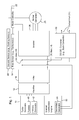
- FIG. 1 is a block diagram of one embodiment of a system for managing an electrical output of a turbogenerator.
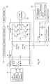
- FIG. 2 shows illustrative schematic representations for corresponding blocks of FIG. 1.
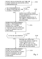
- FIG. 3 is a flow chart of one embodiment of a method for managing an electrical output of a turbogenerator.
- FIG. 4 is a flow chart of another embodiment of a method for managing an electrical output of a turbogenerator.
- FIG. 5 is a block diagram of another embodiment of a system for managing an electrical output of a turbogenerator.
- FIG. 6 is a block diagram of yet another embodiment of a system for managing an electrical output of a turbogenerator.
- FIG. 7 is a flow chart of another embodiment of a method for managing an electrical output of a turbogenerator.
- In FIG. 1 and FIG. 2, a turbogenerator
electrical output 11 of aturbogenerator 10 is coupled to arectifier input 13 of arectifier 12. Arectifier output 15 of therectifier 12 is connected to afilter input 17 of afilter 16. Thefilter 16 filters the direct current signal for the direct current (DC)bus 14. Afilter output 19 of thefilter 16 is coupled to aninverter 26. Theinverter 26 communicates a control signal (e.g., variable frequency or variable pulse width modulated signal) to a motor/generator 28. The motor/generator 28 comprises: (a) a motor or electric drive in a propulsion mode and (b) a generator or alternator during a power generation mode. In the propulsion mode, the motor is capable of rotating a motor output shaft, whereas in the power generation mode the generator converts mechanical rotational energy into electrical energy. It is understood by those of skill in the art that the terms "motor", "generator", or "alternator" could be used generally interchangeably with "motor/generator," without any loss of functionality, limitation of mode, or meaning with the caveat that "alternator" may appropriately refers to alternating current (AC) configurations. - A converter 30 (e.g., DC-DC converter or Buck converter) is coupled across the
direct current bus 14, thefilter output 19, or both to provide a direct current (DC)output port 31. Thefilter output 19 may feed electrical energy to an input of theconverter 30. Theconverter 30 provides direct current (DC) at theoutput port 31 at a desired output level (e.g., higher or lower than the level of the DC bus 14). For example, theconverter 30 regulates a second voltage level (or desired output level) associated with anoutput port 31 to differ from a first voltage level associated with thedirect current bus 14. - A first sensor 18 (e.g., tachometer) is associated with a turbogenerator. The
first sensor 18 measures the rotation per unit time, angular displacement per unit time, rotational velocity, rotational speed, or rotational acceleration of a shaft, rotor, turbine, turbine blade or other rotational member of aturbogenerator 10. In one configuration, thefirst sensor 18 may monitor a number of voltage pulses per unit time associated with therectifier 12 or the back electromotive force (EMF) produced in the windings of theprimary generator 42 to infer or estimate the rotational speed of the shaft, rotor, turbine, or turbine blades. - A
second sensor 48 may comprise any sensor that detects braking or deceleration of the vehicle. For example, thesecond sensor 48 may comprise one or more accelerometers associated with the vehicle, a contact switch or an optical switch associated with the brake pedal of the vehicle, a piezo-electric device associated with the brake actuator or braking pads, a electro-hydraulic flow sensor, or another suitable sensor. Thefirst sensor 18 and thesecond sensor 48 are coupled to amode controller 22 to provide input data or input signals thereto. - The
mode controller 22 controls the motor/generator 28. For example, themode controller 22 may select a propulsion state or an energy generation state of the motor/generator 28 based on the input data or input signals from the sensors (18, 48). Themode controller 22 may comprise a comparator, a logic circuit, a logic unit, programmable digital signal processors, a microcontroller, or other data processor or a software module that determines whether the turbogenerator revolutions per unit time, or first sensor data or a signal representative thereof, exceed a minimum threshold or reference range. If the turbogenerator revolutions per unit time exceed the minimum threshold or range, themode controller 22 may generate one or more control signals to control the states of switches in the switching circuit 24. - In an alternate embodiment, the
mode controller 22 controls one or more states of asecondary generator 20. For example, themode controller 22 may activate (or engage) an electromagnetic clutch to impart rotational energy directly or indirectly from a shaft (e.g., crankshaft) of theinternal combustion engine 50 to thesecondary generator 20 in the second mode, whereas themode controller 22 may deactivate (or disengage) an electromagnetic clutch to remove rotational energy from thesecondary generator 20 in the first mode. - In one embodiment, the
turbogenerator 10 comprises a turbine (e.g., an exhaust-driven turbine) in communication with exhaust gas or steam associated with aninternal combustion engine 50. The turbine is mechanically coupled to a primary generator 42 (e.g., alternator) that generates electrical energy that may be used by one or more components of the vehicle. Although theinternal combustion engine 50 may be run at target or target range of revolutions per unit time (e.g., 1,800 to 2,200 revolutions per minute) of a shaft (e.g., crankshaft) for efficient operation, theinternal combustion engine 50 may be run at virtually any revolutions per unit time within its operational range. A fuel delivery system (e.g., fuel injection system or carburetion system) may be associated with a controller (e.g., regulator) for metering or otherwise regulating the flow of fuel to maintain the target or target range of revolutions per unit time, for example. - The
internal combustion engine 50 is capable of driving the secondary generator 20 (e.g., alternator) to generate electrical power. Thesecondary generator 20 may be associated with a clutch (e.g., an electromagnetic clutch), but is not necessarily associated with a clutch, for coupling and decoupling to mechanical or rotational energy provided by theengine 50. - The electrical output of the
secondary generator 20 may be rectified within thesecondary generator 20 or via a secondary rectifier coupled to an electrical output of thesecondary generator 20. The rectified electrical output of thesecondary generator 20 is coupled to the directcurrent bus 14. For example, the electrical output of thesecondary generator 20 and thefilter 16 are coupled in parallel to theDC bus 14. Therectifier 12 provides isolation to prevent the electrical current generated by thesecondary generator 20 from flowing into the primary generator 42 (e.g., the windings of the primary generator 42). - In one embodiment, as best illustrated in FIG. 2, the
rectifier 12 comprises pairs of diodes. Each pair comprises afirst diode 27 coupled in series to asecond diode 29. An anode of thefirst diode 27 is coupled to one rail of theunrectified DC bus 25, whereas a cathode of thesecond diode 29 is coupled to another rail of theunrectified DC bus 25. - In one embodiment, the
filter 16 may comprise the combination of acapacitor 31 placed in parallel across the rectifiedDC bus 25, and aninductor 33 in series with one rail of theunrectified DC bus 25. Thecapacitor 31 may comprise an electrolytic capacitor or a similar capacitor to smooth voltage ripples (or electrical transients) that might otherwise appear on theDC bus 14. In one configuration, the frequency response ofrectifier 12, thefilter 16 or both is selected to reduce or attenuate unwanted harmonics in the generated electrical energy of theprimary generator 42 by a minimum amount at theDC bus 14. - The
inverter 26 may comprise one or more semiconductors arranged in a switch mode configuration. Here, the semiconductors are shown as NPN transistors (e.g., power switching transistors) for illustrative purposes. Although the schematic representation of theinverter 26 omits biasing networks and control circuitry for the NPN transistors and other components, such biasing networks and control circuitry for switch mode inverters are generally well known. - In general, the
mode controller 22 may provide one or more of the following: (1) biasing networks and control circuitry (e.g., logic circuits) to operate theinverter 26 in one or more distinct modes, (2) control data or control signal to operate the inverter in one or more distinct modes, (3) biasing networks and control circuitry (e.g., logic circuits) to operate thesecondary generator 20 or an electromagnetic clutch associated therewith in one or more distinct states, and (4) control data or control signals to operate thesecondary generator 20 or electromagnetic clutch associated therewith in one or more distinct states. In a first mode, themode controller 22 controls theinverter 26 to support the acceptance of generated electrical energy from theprimary generator 42, thesecondary generator 20, or both. Further, themode controller 22 controls theinverter 26 to support the flow of the generated electrical energy from theprimary generator 42 to theDC bus 14 or the motor/generator 28. In the second mode,mode controller 22 supports the generation of electrical energy by the motor/generator 28 and its flow from the motor/generator 28 to theDC bus 14. - In the first mode, the
inverter 26 may chop or process the DC signal on theDC bus 14 to output an alternating current (AC) output signal suitable for energizing thedrive motor 28. In one example, theinverter 26 provides a variable frequency drive signal with one or more phases for themotor 28. In another example of the first mode, theinverter 26 supports the pulse-width modulation of the inputted DC signal at theinverter input 21 to produce a variable or controllable AC output signal for driving the motor/generator 28. - In the second mode, the
mode controller 22 orinverter 26 may control the switches (e.g., NPN transistors) to regulate the voltage and current of electrical energy output by the motor/generator 28 and to provide rectification of any alternating current output to a direct current output. - In one example, the converter 30 (e.g., DC-DC converter) may comprise a
Buck converter 30. In one embodiment, theconverter 30 accepts a DC input voltage from theDC bus 14 and provides a different DC output voltage at theoutput port 31. For example, theoutput port 31 of theconverter 30 provides a higher or lower voltage DC output. Theoutput port 31 may be used to power auxiliary components, electronics, electric fans, electric motors, electric fuel pumps, electric pumps, or other electrical or electronic devices or vehicular accessories besides thedrive motor 28. Further, theconverter 30 may provide noise isolation or regulation of the DC voltage output at theoutput port 31. - Although the configuration of FIG. 2 illustrates the
converter 30 as a step-downBuck converter 30 in which the DC voltage level from theDC bus 14 is generally decreased, any configuration ofconverter 30 may be used and falls within the scope of the invention. For example, interchanging thediode 31 andinductor 33 in the circuit of FIG. 2 results in a step-upBuck converter 30 or boosting Buck converters that may be used for DC-DC converter 30 in which the DC voltage level from theDC bus 14 is generally increased at theoutput port 31 and higher than that of theDC bus 14. Other types of DC converters for DC-DC converter 30 include inverting, push-pull, half-bridge and full bridge, among other possibilities. Some DC converters may support bi-directional current flow with voltage regulated output foroutput port 31, such that an energy storage device (e.g., battery of a desired voltage level or range) could be coupled across theoutput port 31 to provide reserve electrical energy for the motor/generator 28. - The system of FIG. 1 and FIG. 2 may operate in any of several distinct power generation modes, which may be applied alternately or cumulatively. Under a first mode, a
turbine 40 of theturbogenerator 10 provides electrical power from the turbine's conversion of exhaust gas into mechanical energy. Theprimary generator 42 converts the mechanical energy into electrical energy, which the switching circuit 24 may make available to thedrive motor 28, theconverter 30, or both. The first mode is active when the turbogenerator revolutions per unit time (e.g., RPM) is above or equal to a minimum threshold. - In an alternate embodiment, the first mode may include the
secondary generator 20 providing electrical energy to theDC bus 14 in parallel with the turbogenerator output of theprimary generator 42. For example, themode controller 22 may control (e.g., activate or deactivate) an electromagnetic clutch associated with thesecondary generator 20 to selectively apply or withdraw rotational energy to thesecondary generator 20 from theinternal combustion engine 50 in accordance with load requirements or demand on theDC bus 14. - Under a second mode, the
internal combustion engine 50 mechanically drives asecondary generator 20 to convert mechanical energy into electrical energy. The second mode is generally active when the turbogenerator revolutions per unit time (e.g., RPM) are below the minimum threshold. - In a third mode or regenerative braking mode, the motor/
generator 28 acts as a tertiary generator for the vehicle. In the third mode, the motor/generator 28 or tertiary generator may be coupled to theinverter 26 to facilitate rectification of an alternating current signal provided by themotor 28 or tertiary generator, regulation of the generated electrical current, and voltage, or both rectification and regulation. The third mode is active when the vehicle is braking or when the vehicle is decelerating in accordance with an operator's input or otherwise. - The system for managing electrical output of a turbogenerator may support the simultaneous operation of multiple modes, among the first mode, the second mode and the third mode. To support operation in multiple modes, the
rectifier 12 andinverter 26 facilitate parallel interconnections of two or more outputs associated with theprimary generator 42, thesecondary generator 20, and the tertiary generator (i.e., the motor 28). In an alternate embodiment, one or more diode networks may be used at theDC bus 14 for coupling and isolating the output signals of the generators (42, 20, and 28) in parallel. Each diode network may comprise at least one diode, or multiple diodes in parallel, for a corresponding terminal of the DC voltage bus at a corresponding generator output. For example, a first diode network is placed in series with a DC terminal output (e.g., positive terminal) of theprimary generator 42, a second network is placed in series with the DC terminal output (e.g., a positive terminal) of thesecondary generator 20, and the third diode network is coupled in series with the DC terminal output (e.g., positive terminal) of the tertiary generator, and the appropriate terminals (e.g., cathode terminals where the above DC terminal is positive and anode where the DC terminal polarity is negative) of the diode networks are coupled together at a common connection node that feeds the common DC terminal (e.g., positive terminal) of theDC bus 14. The diode networks facilitate simultaneous application of or power generation in at least two of the first mode, the second mode, and the third mode. Further, such diode networks may support redundancy or a controlled failure mode, where therectifier 12 is disabled or fails. - FIG. 3 is a method for managing electrical output of a
turbogenerator 10 in accordance with multiple modes. The system of FIG. 1 and FIG. 2 may be applied to carry out the method of FIG. 3. The method of FIG. 3 begins in step S100. - In step S100, a
first sensor 18 detects revolutions per unit time (e.g., revolutions per minute (RPM)) for aturbogenerator 10. Thefirst sensor 18 may comprise a tachometer or another sensor for measuring turbogenerator revolutions per unit time of a shaft, rotor, turbine, or other rotation member associated with theturbogenerator 10. For example, the shaft, rotor, or other rotational member of theprimary generator 42 may be associated with a magnet (or electromagnet) for rotation therewith. Alternately, a shaft, rotor, turbine blades or other rotational member of theturbine 40 may be associated with a magnet for rotation therewith. A stationary sensing coil coupled to a detection circuit may measure or count current fluctuations (or voltage fluctuations) per unit time imparted into coil to estimate the revolutions per unit time of the shaft, rotor, turbine blades, or other rotational member. - In step S102, the
mode controller 22 determines if turbogenerator revolutions per unit time meet or exceed a minimum threshold. The user may establish the minimum threshold that is proportional to or based on the electrical energy (e.g., current level, voltage level, or both) generated by theturbogenerator 10 at or above the minimum threshold, for example. The electrical energy generated by theturbogenerator 10 below the threshold may be insufficient to produce a reliable direct current (DC) waveform at theDC bus 14 that is capable of driving themotor 28 via theinverter 26. If the turbogenerator revolutions per unit time meet or exceed the minimum threshold, the method continues with step S104. However, if the turbogenerator revolutions per unit time do not exceed the minimum threshold, the method continues with step S108. - In step S104, the
turbogenerator 10 supplies or outputs electrical energy to at least one of arectifier 12 and a direct current (DC)bus 14 in a first mode. For example, therectifier 12 rectifies the outputted electrical energy from the turbogenerator output prior 11 to applying it to the directcurrent bus 14 in the first mode. Themode controller 22 controls theinverter 26 to accept output electrical energy from a turbogenerator output 11 (e.g., primary generator output) in a first mode. - In one illustrative example, step S104 may be carried out as follows. The
turbine 40 imparts mechanical rotation of theprimary generator 42 to produce alternating current (AC) electrical energy, which is rectified by therectifier 12. Therectifier output 15 and thefilter input 17 are associated with the unfiltered or unrectified DC bus. Thefilter 16 filters the rectified signal for thefilter output 19. Thefilter output 19 may provide the generated electrical energy to theDC bus 14. - In step S106, following step S104, or simultaneously therewith, the
mode controller 22 controls theinverter 26 to accept to output electrical energy from theprimary generator 42 for theelectric drive motor 28 in the first mode. In turn, theconverter 30 provides a DC output voltage at theDC output port 31. - In step S108, the
secondary generator 20 supplies or outputs a generator output to the directcurrent bus 14 in a second mode. Further, themode controller 22 controls theinverter 26 to accept output electrical power from a generator output of thesecondary generator 20 to the directcurrent bus 14 in the second mode. Step S108 may be carried out in accordance with several techniques that may be applied cumulatively or separately. - The method of FIG. 4 is similar to the method of FIG. 3, except steps S107 and S109 are added. Like reference numbers in FIG. 3 and FIG. 4 indicate like steps or procedures. Step S107 may be executed after step S106, for example.
- In step S107, a
mode controller 22 orsecond sensor 48 determines whether a vehicle is braking or whether an operator is applying the brakes of the braking system. The braking system may comprise a hydraulic braking system, an electrical braking system, a mechanical braking system, a friction braking system, a magnetic or electromagnetic braking system, or the like. If the vehicle is braking or if an operator is applying the brakes, the method continues with step S109. However, if the vehicle is not braking, the method continues with step S104. - In step S109, the electric drive motor/generator 28 (which is also referred to as the tertiary generator when operating in a power generation mode) outputs electrical energy to the direct current bus 14 (e.g., via the inverter 26), while operating in a power generation mode or regenerative braking mode. The drive motor/
generator 28 may complement or supersede the braking function of the other braking system of the vehicle, during step S109. In accordance with one example of carrying out step S109, themode controller 22 may control theinverter 26 to act as a supplemental rectifier and a regulator of electrical output generated by the motor/generator 28. - Accordingly, in step S109 the
drive motor 28 is used in a power generation mode as a tertiary power generator by opposing the motion or momentum of the vehicle, either alone or in combination with the braking system of the vehicle. In step S109, themode controller 22 may determine that the drive motor/generator 28 is generally not used as a tertiary power generator if the vehicle is not moving or if the operator needs to increase the speed or acceleration of the vehicle, or if the internal combustion engine does not indirectly or directly drive at least one wheel of the vehicle, for example. - In step S106, the
turbogenerator 10 orprimary generator 42 provides the outputted electrical energy to at least one of a DC output port and the electric drive motor in the first mode. Step S106 is described in greater detail in conjunction with FIG. 3. - The system of FIG. 5 is similar to the system of FIG. 1, except the system of FIG. 5 deletes the
second sensor 48. Like reference numbers in FIG. 1, FIG. 2, and FIG. 5 indicate like elements. - The system of FIG. 6 is similar to the system of FIG. 1, except the system of FIG. 6 replaces
first sensor 18 withfirst sensor 118 and deletes thesecond sensor 48. Like reference numbers in FIG. 1, FIG. 2, and FIG. 4 indicate like elements. - The
first sensor 118 comprises an electrical level sensor. For example, the electrical level sensor may comprise a voltage meter, a current meter, a comparator, a resistive bridge, or another circuit for measuring changes in current or voltage or signal quality generated by theprimary generator 42 of theturbogenerator 10. Rather than measuring the turbogenerator revolutions per unit time, thefirst sensor 118 measures changes in current, voltage or signal quality to facilitate determination of the proper mode by themode controller 22. For example, if the electrical output current level or voltage level (e.g., current level or voltage level) of theprimary generator 42 falls above or equals a minimum threshold, themode controller 22 may instruct the switching circuit 124 to operate in a first mode. However, if the current level or voltage level is less than a minimum threshold, themode controller 22 may instruct the switching circuit 124 to operate in a second mode. - The method of FIG. 7 is similar to the method of FIG. 3, except FIG. 7 replaces step S100 and S102, with steps S200 and S202, respectively. Like reference numbers in FIG. 7 and FIG. 3 indicate like steps or procedures.
- In step S200, a
first sensor 118 detects an electrical output level (e.g., current level, voltage level) outputted by theturbogenerator 10 or theprimary generator 42 during an evaluation time window. As previously indicated, thespeed sensor 118 may comprise a volt meter, a voltage level detector, a comparator, a current meter, a current detector, or another sensor for measuring an electrical output of theprimary generator 42. - In step S202, the
mode controller 22 determines if the detected electrical level exceeds a minimum threshold. The user may establish the minimum threshold with reference to the electrical energy (e.g., current level, voltage level, or both) generated by theturbogenerator 10 under various load conditions, for example. The electrical energy generated by theturbogenerator 10 below the threshold may be insufficient to produce a reliable direct current (DC) waveform at theDC bus 14 that is capable of driving themotor 28 via theinverter 26. If the detected electrical level exceeds a minimum threshold, the method continues with step S104. However, if the detected electrical level does not exceed the minimum threshold, the method continues with step S108. Steps S104 and S108 were previously described in conjunction with FIG. 3, and apply equally to FIG. 7.
Claims (15)
- A method for managing an electrical output of a turbogenerator (10), the method comprising:detecting revolutions per unit time associated with a turbogenerator (10);outputting electrical energy from a turbogenerator output (11) to at least one of a rectifier (12) and a direct current bus (14) in a first mode where the detected turbogenerator revolutions per unit time meet or exceed a minimum threshold; andproviding the outputted electrical energy to at least one of an electric drive motor (28) and a direct current port (31) in the first mode.
- The method according to claim 1 further comprising:outputting electrical power from a generator (42) output at the direct current bus (14) in a second mode where turbogenerator revolutions per unit time are less than the minimum threshold.
- The method according to claim 1 or 2 further comprising:rectifying the outputted electrical energy from the turbogenerator output (11) prior to applying it to the direct current bus (14) in the first mode.
- The method according to one of claims 1 to 3 wherein the providing further comprises inverting the outputted electrical energy for application to the electric drive motor (28).
- The method according to one of claims 1 to 3 further comprising:regulating a second voltage level associated with an output port (31) to differ from a first voltage level associated with the direct current bus (14).
- The method according to one of claims 1 to 5 further comprising:sensing whether or not a vehicle is braking; andusing the electric drive motor (28) to generate electrical energy during the braking of the vehicle in a third mode.
- The method according to one of claims 1 to 5 further comprising:supporting simultaneous application of at least two of the first mode, the second mode and the third mode via a diode network.
- A system for managing an electrical output of a turbogenerator (10), the system comprising:a first sensor (18) for detecting revolutions per unit time associated with a shaft or a rotor of a turbogenerator (10);a direct current bus (14);a turbogenerator (10) for outputting electrical energy from a turbogenerator output (11) to feed the direct current bus (14) in a first mode where the detected turbogenerator revolutions per unit time meet or exceed a minimum threshold;an electric drive motor (28) for accepting the outputted electrical energy in the first mode; anda generator (42) for outputting electrical power from a generator output to the direct current bus (14) in a second mode where the detected turbogenerator revolutions per unit time are less than the minimum threshold.
- The system according to claim 8 further comprising:a rectifier (12) for rectifying the outputted electrical energy from the turbogenerator output (11) prior to applying it to the direct current bus (14) in the first mode.
- The system according to claim 8 or 9 further comprising:an inverter (26) for inverting the received electrical energy prior to applying it to the electric drive motor (28), where the electrical drive motor (28) is associated with the direct current bus (14).
- The system according to claim 10 further comprising:a switching circuit (24) for forming an interconnection between the turbogenerator output (11) and an inverter input of the inverter (26) in the first mode.
- The system according to one of claims 8 to 11 further comprising:a converter (30) for converting a first voltage level associated with the direct current bus (14) to a second voltage level associated with an output port (31).
- The system according to claim 12 further comprising:a switching circuit (24) for forming an interconnection between the turbogenerator output (11) and a converter input of the converter (30) in the first mode.
- The system according to one of claims 8 to 13 further comprising:a rectifier (12);a second sensor (48) for determining whether or not the vehicle is braking;a mode controller (22) facilitating a third mode in response to vehicle braking in which the electric drive motor (28) is coupled to the rectifier (12) for generating electrical energy for the direct current bus (14).
- The system according to claim 14 further comprising:a diode network to facilitate simultaneous application of at least two of the first mode, the second mode and the third mode.
Applications Claiming Priority (2)
| Application Number | Priority Date | Filing Date | Title |
|---|---|---|---|
| US78116706P | 2006-03-10 | 2006-03-10 | |
| US11/521,242 US7541687B2 (en) | 2006-03-10 | 2006-09-13 | Method and system for managing an electrical output of a turbogenerator |
Publications (3)
| Publication Number | Publication Date |
|---|---|
| EP1833158A2 true EP1833158A2 (en) | 2007-09-12 |
| EP1833158A3 EP1833158A3 (en) | 2017-03-01 |
| EP1833158B1 EP1833158B1 (en) | 2020-01-01 |
Family
ID=38137411
Family Applications (1)
| Application Number | Title | Priority Date | Filing Date |
|---|---|---|---|
| EP07102855.9A Ceased EP1833158B1 (en) | 2006-03-10 | 2007-02-22 | Method and system for managing an electrical output of a turbogenerator |
Country Status (2)
| Country | Link |
|---|---|
| US (2) | US7541687B2 (en) |
| EP (1) | EP1833158B1 (en) |
Cited By (4)
| Publication number | Priority date | Publication date | Assignee | Title |
|---|---|---|---|---|
| FR2931210A1 (en) * | 2008-05-13 | 2009-11-20 | Mitsubishi Electric Corp | ENGINE STARTING SYSTEM |
| EP2131483A1 (en) * | 2008-06-05 | 2009-12-09 | Schneider Toshiba Inverter Europe SAS | Speed regulator with super capacitor |
| FR2971472A1 (en) * | 2011-02-16 | 2012-08-17 | Peugeot Citroen Automobiles Sa | Vehicle i.e. four-wheeled hybrid vehicle, has electric machine for recovering energy on level of exhaust of vehicle, and two voltage level inverter associated with energy storage element and connected with electric machines |
| EP2873827A1 (en) * | 2013-11-14 | 2015-05-20 | Hyundai Motor Company | Turbocharger system for additionally supplying compressed air to intake manifold |
Families Citing this family (31)
| Publication number | Priority date | Publication date | Assignee | Title |
|---|---|---|---|---|
| US7541687B2 (en) * | 2006-03-10 | 2009-06-02 | Deere & Company | Method and system for managing an electrical output of a turbogenerator |
| JP4079178B2 (en) * | 2006-04-19 | 2008-04-23 | ダイキン工業株式会社 | Power converter, control method therefor, and air conditioner |
| US7622817B2 (en) * | 2006-12-13 | 2009-11-24 | General Electric Company | High-speed high-pole count generators |
| EP2014894B1 (en) * | 2007-07-09 | 2010-10-13 | Magneti Marelli S.p.A. | A control method for a turbocharger supercharged internal combustion engine |
| DE102007043795A1 (en) * | 2007-09-13 | 2009-04-02 | Siemens Ag | Control system for a technical system and method for operating a process control system |
| US8209107B2 (en) * | 2008-01-23 | 2012-06-26 | Hamilton Sundstrand Corporation | Electric motor for fuel pump with improved shutdown features |
| US7893554B2 (en) * | 2008-02-28 | 2011-02-22 | Deere & Company | Turbo compounding system |
| CN102017395B (en) * | 2008-04-28 | 2014-08-06 | 大金工业株式会社 | DC-AC converter control device and power conversion device |
| JP5130109B2 (en) * | 2008-05-09 | 2013-01-30 | 本田技研工業株式会社 | Cycloconverter generator |
| JP2010075036A (en) * | 2008-08-22 | 2010-04-02 | Fuji Heavy Ind Ltd | Controlling apparatus of electric automobile |
| US8522756B2 (en) * | 2009-10-28 | 2013-09-03 | Deere & Company | Interstage exhaust gas recirculation system for a dual turbocharged engine having a turbogenerator system |
| US20110094224A1 (en) * | 2009-10-28 | 2011-04-28 | Sheidler Alan D | Metering exhaust gas recirculation system for a turbocharged engine having a turbogenerator system |
| US8522757B2 (en) * | 2009-10-28 | 2013-09-03 | Deere & Company | Metering exhaust gas recirculation system for a dual turbocharged engine having a turbogenerator system |
| JP5700237B2 (en) * | 2010-07-08 | 2015-04-15 | 株式会社Ihi | Waste heat recovery device |
| DE102011012164A1 (en) * | 2011-02-23 | 2012-08-23 | Bombardier Transportation Gmbh | Arrangement and method for supplying electrical traction motors in a rail vehicle, in particular in a train, with electrical energy |
| SI2737621T1 (en) * | 2011-07-26 | 2022-10-28 | Moog Inc. | Electric motor clamping system |
| US10014790B2 (en) * | 2012-04-19 | 2018-07-03 | Illinois Tool Works Inc. | Dual function solid state converter |
| US9407187B2 (en) * | 2012-06-28 | 2016-08-02 | General Electric Company | System and method for improving response time of a braking unit |
| US9413217B2 (en) | 2012-06-28 | 2016-08-09 | General Electric Company | Electromagnetic braking systems and methods |
| US9601918B2 (en) | 2012-06-28 | 2017-03-21 | General Electric Company | Systems and methods for controlling acceleration of a power generator |
| GB201219916D0 (en) * | 2012-11-06 | 2012-12-19 | Rolls Royce Plc | An electrical generation arrangement for an aircraft |
| US9407134B2 (en) * | 2013-12-11 | 2016-08-02 | Baker Hughes Incorporated | Systems and methods for limiting current inrush in electric drive systems |
| CA2935772C (en) * | 2014-02-04 | 2021-08-03 | Canrig Drilling Technology Ltd. | Generator load control |
| JP6423891B2 (en) * | 2014-03-12 | 2018-11-14 | ユチンソンHutchinson | Hydraulic vibration suppression device provided with a generator |
| DE102016115588A1 (en) * | 2016-08-23 | 2018-03-01 | Claas Tractor Sas | Agricultural working machine with turbocharger |
| DE112017005590T5 (en) * | 2016-11-07 | 2019-08-29 | Ihi Corporation | GAS ENERGY RECOVERY UNIT |
| US10718598B2 (en) | 2017-06-23 | 2020-07-21 | Hamilton Sundstrand Corporation | Series hybrid architecture for an unmanned underwater vehicle propulsion system |
| CN108512424A (en) * | 2018-05-25 | 2018-09-07 | 湖南恒信电气有限公司 | Regenerating braking energy energy storage energy consumption mixed type twin voltage standard absorption plant |
| JP7179492B2 (en) * | 2018-05-25 | 2022-11-29 | 三菱重工業株式会社 | supercharging system |
| FR3083399B1 (en) * | 2018-06-28 | 2020-08-21 | Valeo Equip Electr Moteur | SWITCH CONTROL SYSTEM, SWITCHING ARM AND ELECTRICAL INSTALLATION |
| CN111791816B (en) * | 2020-06-30 | 2021-11-12 | 东风商用车有限公司 | BSG motor and double-generator energy supply system for commercial vehicle |
Family Cites Families (75)
| Publication number | Priority date | Publication date | Assignee | Title |
|---|---|---|---|---|
| US4211930A (en) * | 1978-07-24 | 1980-07-08 | Fengler Werner H | Vehicle propulsion system by individual stepping motors from continuously-running engine-driven alternator and/or pulsating battery current |
| US4414805A (en) * | 1981-11-27 | 1983-11-15 | General Motors Corporation | Hybrid gas turbine engine and flywheel propulsion system |
| CH658884A5 (en) * | 1984-10-01 | 1986-12-15 | Cerac Inst Sa | INTERNAL COMBUSTION ENGINE UNIT. |
| EP0223419B1 (en) * | 1985-10-19 | 1990-12-19 | Isuzu Motors Limited | Energy recovery apparatus for a turbocharged compound engine |
| JPS62104403A (en) * | 1985-10-29 | 1987-05-14 | Isuzu Motors Ltd | Driving device for vehicle |
| JP2510855B2 (en) * | 1986-02-10 | 1996-06-26 | いすゞ自動車株式会社 | Energy recovery device in vehicle |
| JPH086583B2 (en) * | 1987-04-24 | 1996-01-24 | 株式会社日立製作所 | Exhaust energy recovery method for internal combustion engine |
| JPS63302119A (en) * | 1987-05-30 | 1988-12-09 | Isuzu Motors Ltd | Exhaust energy recovering engine |
| JP2640757B2 (en) * | 1988-07-18 | 1997-08-13 | 株式会社いすゞセラミックス研究所 | Control device for turbocharger |
| JP2526100B2 (en) * | 1988-07-18 | 1996-08-21 | 株式会社 いすゞセラミックス研究所 | Supercharger control device |
| JPH02223627A (en) * | 1989-02-27 | 1990-09-06 | Isuzu Motors Ltd | Energy recovery device of vehicle |
| US5172784A (en) * | 1991-04-19 | 1992-12-22 | Varela Jr Arthur A | Hybrid electric propulsion system |
| US5343970A (en) * | 1992-09-21 | 1994-09-06 | Severinsky Alex J | Hybrid electric vehicle |
| DE4311230C2 (en) * | 1993-04-02 | 1996-12-19 | Mannesmann Ag | Non-track-bound vehicle with an electric motor |
| US5568023A (en) * | 1994-05-18 | 1996-10-22 | Grayer; William | Electric power train control |
| DE4435613C1 (en) * | 1994-10-05 | 1996-03-28 | Fichtel & Sachs Ag | Hybrid drive for a road vehicle |
| JPH08336205A (en) * | 1995-04-07 | 1996-12-17 | Nippon Soken Inc | Battery charging device for hybrid vehicle |
| JP3534271B2 (en) * | 1995-04-20 | 2004-06-07 | 株式会社エクォス・リサーチ | Hybrid vehicle |
| FR2743343B1 (en) * | 1996-01-05 | 1998-02-13 | Smh Management Services Ag | DRIVE SYSTEM FOR A HYBRID-DRIVEN MOTOR VEHICLE AND ITS DRIVING METHOD |
| US5831341A (en) * | 1996-05-02 | 1998-11-03 | Satcon Technologies Corporation | Turboalternator for hybrid motor vehicle |
| US5789824A (en) * | 1996-05-02 | 1998-08-04 | Chrysler Corporation | Cooling of turboalternator for hybrid motor vehicle |
| US5925993A (en) * | 1996-05-02 | 1999-07-20 | Chrysler Corporation | Power control architecture for a hybrid power source |
| US5893423A (en) * | 1996-05-02 | 1999-04-13 | Satcon Technology Corporation | Integration of turboalternator for hybrid motor vehicle |
| JP3288928B2 (en) * | 1996-06-14 | 2002-06-04 | 日野自動車株式会社 | In-vehicle battery control device |
| US6097164A (en) * | 1997-02-04 | 2000-08-01 | Derosa; Glenn P. | On board power regeneration system for electrically operated vehicles |
| JP3767103B2 (en) * | 1997-07-16 | 2006-04-19 | 日産自動車株式会社 | Electric vehicle control device |
| US6079211A (en) * | 1997-08-14 | 2000-06-27 | Turbodyne Systems, Inc. | Two-stage supercharging systems for internal combustion engines |
| US6784565B2 (en) * | 1997-09-08 | 2004-08-31 | Capstone Turbine Corporation | Turbogenerator with electrical brake |
| US5903116A (en) * | 1997-09-08 | 1999-05-11 | Capstone Turbine Corporation | Turbogenerator/motor controller |
| US6487096B1 (en) * | 1997-09-08 | 2002-11-26 | Capstone Turbine Corporation | Power controller |
| AU1085499A (en) * | 1997-10-14 | 1999-05-03 | Capstone Turbine Corporation | Vehicle powered by a fuel cell/gas turbine combination |
| US6020697A (en) * | 1997-11-14 | 2000-02-01 | Honda Giken Kogyo Kabushiki Kaisha | Hybrid vehicle |
| US6012289A (en) * | 1997-11-19 | 2000-01-11 | Caterpillar Inc. | Apparatus and method for utilizing a learned wastegate control signal for controlling turbocharger operation |
| US6170251B1 (en) * | 1997-12-19 | 2001-01-09 | Mark J. Skowronski | Single shaft microturbine power generating system including turbocompressor and auxiliary recuperator |
| US6125625A (en) * | 1997-12-20 | 2000-10-03 | Alliedsignal, Inc. | Low NOx conditioner system for a microturbine power generating system |
| TW390936B (en) * | 1997-12-20 | 2000-05-21 | Allied Signal Inc | Microturbine power generating system |
| CA2318944C (en) * | 1997-12-20 | 2007-09-11 | Alliedsignal Inc. | Constant turbine inlet temperature control of a microturbine power generating system |
| JP3536658B2 (en) * | 1998-03-31 | 2004-06-14 | 日産自動車株式会社 | Drive control device for hybrid vehicle |
| US6958550B2 (en) * | 1998-04-02 | 2005-10-25 | Capstone Turbine Corporation | Method and system for control of turbogenerator power and temperature |
| US20040135436A1 (en) * | 1998-04-02 | 2004-07-15 | Gilbreth Mark G | Power controller system and method |
| KR20030011347A (en) * | 1998-04-28 | 2003-02-07 | 가부시키가이샤 히타치세이사쿠쇼 | Hybrid car and method for driving hybrid car |
| US6066898A (en) * | 1998-08-14 | 2000-05-23 | Alliedsignal Inc. | Microturbine power generating system including variable-speed gas compressor |
| US6209672B1 (en) * | 1998-09-14 | 2001-04-03 | Paice Corporation | Hybrid vehicle |
| US6338391B1 (en) * | 1999-03-01 | 2002-01-15 | Paice Corporation | Hybrid vehicles incorporating turbochargers |
| US6554088B2 (en) * | 1998-09-14 | 2003-04-29 | Paice Corporation | Hybrid vehicles |
| US6757597B2 (en) * | 2001-01-31 | 2004-06-29 | Oshkosh Truck | A/C bus assembly for electronic traction vehicle |
| DE60132123T2 (en) * | 2000-03-01 | 2008-04-30 | Hitachi, Ltd. | Electric generator system for vehicles and its control method |
| US6683389B2 (en) * | 2000-06-30 | 2004-01-27 | Capstone Turbine Corporation | Hybrid electric vehicle DC power generation system |
| JP2002038962A (en) * | 2000-07-24 | 2002-02-06 | Hitachi Ltd | Control device for internal combustion engine with turbocharger |
| CN1195154C (en) * | 2000-10-05 | 2005-03-30 | 日产自动车株式会社 | Control of supercharger |
| US20020163819A1 (en) * | 2000-11-07 | 2002-11-07 | Treece William A. | Hybrid microturbine/fuel cell system providing air contamination control |
| US6639328B2 (en) * | 2000-12-19 | 2003-10-28 | Capstone Turbine Corporation | Microturbine/capacitor power distribution system |
| US6787933B2 (en) * | 2001-01-10 | 2004-09-07 | Capstone Turbine Corporation | Power generation system having transient ride-through/load-leveling capabilities |
| US6812586B2 (en) * | 2001-01-30 | 2004-11-02 | Capstone Turbine Corporation | Distributed power system |
| US6612386B2 (en) * | 2001-05-30 | 2003-09-02 | General Motors Corporation | Apparatus and method for controlling a hybrid vehicle |
| EP1296441B1 (en) * | 2001-09-25 | 2006-08-16 | ABB Schweiz AG | Power generating arrangement |
| US20040080165A1 (en) * | 2001-12-31 | 2004-04-29 | Capstone Turbine Corporation | Turbogenerator/motor controller with ancillary energy storage/discharge |
| JP3952974B2 (en) * | 2003-03-17 | 2007-08-01 | トヨタ自動車株式会社 | Control device for internal combustion engine |
| JP3951951B2 (en) * | 2003-04-03 | 2007-08-01 | トヨタ自動車株式会社 | Control device for internal combustion engine |
| US7061131B2 (en) * | 2003-06-13 | 2006-06-13 | General Electric Company | Method and system for optimizing energy storage in hybrid off-highway vehicle systems and trolley connected OHV systems |
| US6962223B2 (en) * | 2003-06-26 | 2005-11-08 | George Edmond Berbari | Flywheel-driven vehicle |
| JP2005201146A (en) * | 2004-01-15 | 2005-07-28 | Denso Corp | Supercharger position detection device |
| US7002317B2 (en) * | 2004-02-18 | 2006-02-21 | Honeywell International Inc. | Matched reactance machine power-generation system |
| TWI251645B (en) * | 2004-03-02 | 2006-03-21 | Ind Tech Res Inst | Reluctance brake device |
| JP4124143B2 (en) * | 2004-03-04 | 2008-07-23 | トヨタ自動車株式会社 | Control device for supercharger with electric motor |
| JP4479488B2 (en) * | 2004-12-01 | 2010-06-09 | 株式会社デンソー | Exhaust power generator |
| AR052402A1 (en) * | 2005-07-18 | 2007-03-21 | Vignolo Gustavo Gabriel | METHOD OF SPEED MEASUREMENT IN TURBO-INTERNAL COMBUSTION MOTOR FEEDERS BY VIBRATION ANALYSIS, SOFWARE AND EQUIPMENT TO PERFORM IT |
| US7478533B2 (en) * | 2005-08-03 | 2009-01-20 | Honda Motor Co., Ltd. | Engine system with a supercharger |
| US7541687B2 (en) * | 2006-03-10 | 2009-06-02 | Deere & Company | Method and system for managing an electrical output of a turbogenerator |
| US7471008B2 (en) * | 2006-03-10 | 2008-12-30 | Deere & Company | Method and system for controlling a rotational speed of a rotor of a turbogenerator |
| US7336000B2 (en) * | 2006-04-20 | 2008-02-26 | Deere & Company | Electrical power regulation for a turbogenerator and generator associated with an internal combustion engine |
| GB0624599D0 (en) * | 2006-12-09 | 2007-01-17 | Aeristech Ltd | Engine induction system |
| US7797938B2 (en) * | 2007-07-31 | 2010-09-21 | Caterpillar Inc | Energy recovery system |
| US7921944B2 (en) * | 2007-10-29 | 2011-04-12 | Ford Global Technologies, Llc | Compression system for internal combustion engine including a rotationally uncoupled exhaust gas turbine |
| US7893554B2 (en) * | 2008-02-28 | 2011-02-22 | Deere & Company | Turbo compounding system |
-
2006
- 2006-09-13 US US11/521,242 patent/US7541687B2/en active Active
-
2007
- 2007-02-22 EP EP07102855.9A patent/EP1833158B1/en not_active Ceased
-
2009
- 2009-04-27 US US12/430,683 patent/US7781904B2/en active Active
Cited By (5)
| Publication number | Priority date | Publication date | Assignee | Title |
|---|---|---|---|---|
| FR2931210A1 (en) * | 2008-05-13 | 2009-11-20 | Mitsubishi Electric Corp | ENGINE STARTING SYSTEM |
| EP2131483A1 (en) * | 2008-06-05 | 2009-12-09 | Schneider Toshiba Inverter Europe SAS | Speed regulator with super capacitor |
| FR2932327A1 (en) * | 2008-06-05 | 2009-12-11 | Schneider Toshiba Inverter | SPEED DRIVE WITH SUPER CAPACITOR |
| FR2971472A1 (en) * | 2011-02-16 | 2012-08-17 | Peugeot Citroen Automobiles Sa | Vehicle i.e. four-wheeled hybrid vehicle, has electric machine for recovering energy on level of exhaust of vehicle, and two voltage level inverter associated with energy storage element and connected with electric machines |
| EP2873827A1 (en) * | 2013-11-14 | 2015-05-20 | Hyundai Motor Company | Turbocharger system for additionally supplying compressed air to intake manifold |
Also Published As
| Publication number | Publication date |
|---|---|
| US7541687B2 (en) | 2009-06-02 |
| US7781904B2 (en) | 2010-08-24 |
| EP1833158A3 (en) | 2017-03-01 |
| US20070210584A1 (en) | 2007-09-13 |
| EP1833158B1 (en) | 2020-01-01 |
| US20090224541A1 (en) | 2009-09-10 |
Similar Documents
| Publication | Publication Date | Title |
|---|---|---|
| EP1833158B1 (en) | Method and system for managing an electrical output of a turbogenerator | |
| EP3329587B1 (en) | Braking energy recovery system for an electric motor and method | |
| US7598623B2 (en) | Distinguishing between different transient conditions for an electric power generation system | |
| CN104024038B (en) | Method and apparatus for triggering motor | |
| EP1833159B1 (en) | Method and system for controlling a rotational speed of a rotor of a turbogenerator | |
| CN101636901A (en) | Power Generation Systems with Multiple Generators and/or Inverters | |
| JP5367008B2 (en) | Control device for power converter | |
| CN101926086A (en) | Rotating electric machine control system and vehicle drive system | |
| JP2006288184A (en) | SR generator | |
| CN101926087B (en) | Rotating electrical machine control systems and vehicle drive systems | |
| JP2011162178A (en) | Power generation device equipped on vehicle | |
| EP3441255B1 (en) | Electrical power system for hybrid or electric vehicle | |
| JP2011166910A (en) | Apparatus for control of power converter | |
| RU2361356C1 (en) | Method and device for control of asynchronous motor | |
| US7479746B2 (en) | Power converter for an electric engine start system | |
| US8704497B2 (en) | Control device for vehicle AC generator | |
| US7329960B1 (en) | System and method for propelling a large land-based vehicle using a dual function brushless dynamoelectric machine | |
| CN101741305A (en) | Controller of energy-saving and noise reduction digital generator | |
| FI121293B (en) | Braking function control | |
| WO2023228436A1 (en) | Electric power conversion device | |
| JP2026055251A (en) | Converter control unit | |
| JPH0274419A (en) | Power device for vehicle | |
| JPH06233597A (en) | Drive circuit for turbocharger direct-coupled rotating electric machine | |
| JP2000341981A (en) | AC motor control device | |
| JP2003111306A (en) | Operation control method of uninterruptible power supply |
Legal Events
| Date | Code | Title | Description |
|---|---|---|---|
| PUAI | Public reference made under article 153(3) epc to a published international application that has entered the european phase |
Free format text: ORIGINAL CODE: 0009012 |
|
| AK | Designated contracting states |
Kind code of ref document: A2 Designated state(s): AT BE BG CH CY CZ DE DK EE ES FI FR GB GR HU IE IS IT LI LT LU LV MC NL PL PT RO SE SI SK TR |
|
| AX | Request for extension of the european patent |
Extension state: AL BA HR MK YU |
|
| PUAL | Search report despatched |
Free format text: ORIGINAL CODE: 0009013 |
|
| AK | Designated contracting states |
Kind code of ref document: A3 Designated state(s): AT BE BG CH CY CZ DE DK EE ES FI FR GB GR HU IE IS IT LI LT LU LV MC NL PL PT RO SE SI SK TR |
|
| AX | Request for extension of the european patent |
Extension state: AL BA HR MK RS |
|
| RIC1 | Information provided on ipc code assigned before grant |
Ipc: H02J 7/14 20060101ALN20170125BHEP Ipc: B60W 10/08 20060101ALI20170125BHEP Ipc: B60W 10/26 20060101ALI20170125BHEP Ipc: B60L 11/12 20060101ALI20170125BHEP Ipc: H02P 9/00 20060101AFI20170125BHEP Ipc: H02P 9/48 20060101ALI20170125BHEP Ipc: F02D 41/00 20060101ALN20170125BHEP |
|
| STAA | Information on the status of an ep patent application or granted ep patent |
Free format text: STATUS: REQUEST FOR EXAMINATION WAS MADE |
|
| 17P | Request for examination filed |
Effective date: 20170901 |
|
| RBV | Designated contracting states (corrected) |
Designated state(s): AT BE BG CH CY CZ DE DK EE ES FI FR GB GR HU IE IS IT LI LT LU LV MC NL PL PT RO SE SI SK TR |
|
| AKX | Designation fees paid |
Designated state(s): DE FR GB |
|
| AXX | Extension fees paid |
Extension state: BA Extension state: AL Extension state: MK Extension state: HR Extension state: RS |
|
| STAA | Information on the status of an ep patent application or granted ep patent |
Free format text: STATUS: EXAMINATION IS IN PROGRESS |
|
| 17Q | First examination report despatched |
Effective date: 20180830 |
|
| GRAP | Despatch of communication of intention to grant a patent |
Free format text: ORIGINAL CODE: EPIDOSNIGR1 |
|
| STAA | Information on the status of an ep patent application or granted ep patent |
Free format text: STATUS: GRANT OF PATENT IS INTENDED |
|
| RIC1 | Information provided on ipc code assigned before grant |
Ipc: H02J 7/14 20060101ALN20190701BHEP Ipc: B60L 50/15 20190101ALI20190701BHEP Ipc: F02D 41/00 20060101ALN20190701BHEP Ipc: H02P 9/00 20060101AFI20190701BHEP Ipc: B60K 6/46 20071001ALI20190701BHEP Ipc: H02P 9/48 20060101ALI20190701BHEP Ipc: B60L 50/13 20190101ALI20190701BHEP |
|
| INTG | Intention to grant announced |
Effective date: 20190726 |
|
| GRAS | Grant fee paid |
Free format text: ORIGINAL CODE: EPIDOSNIGR3 |
|
| GRAA | (expected) grant |
Free format text: ORIGINAL CODE: 0009210 |
|
| STAA | Information on the status of an ep patent application or granted ep patent |
Free format text: STATUS: THE PATENT HAS BEEN GRANTED |
|
| AK | Designated contracting states |
Kind code of ref document: B1 Designated state(s): DE FR GB |
|
| REG | Reference to a national code |
Ref country code: GB Ref legal event code: FG4D |
|
| REG | Reference to a national code |
Ref country code: DE Ref legal event code: R096 Ref document number: 602007059687 Country of ref document: DE |
|
| REG | Reference to a national code |
Ref country code: DE Ref legal event code: R097 Ref document number: 602007059687 Country of ref document: DE |
|
| PLBE | No opposition filed within time limit |
Free format text: ORIGINAL CODE: 0009261 |
|
| STAA | Information on the status of an ep patent application or granted ep patent |
Free format text: STATUS: NO OPPOSITION FILED WITHIN TIME LIMIT |
|
| 26N | No opposition filed |
Effective date: 20201002 |
|
| PG25 | Lapsed in a contracting state [announced via postgrant information from national office to epo] |
Ref country code: FR Free format text: LAPSE BECAUSE OF NON-PAYMENT OF DUE FEES Effective date: 20200301 |
|
| GBPC | Gb: european patent ceased through non-payment of renewal fee |
Effective date: 20200401 |
|
| PG25 | Lapsed in a contracting state [announced via postgrant information from national office to epo] |
Ref country code: GB Free format text: LAPSE BECAUSE OF NON-PAYMENT OF DUE FEES Effective date: 20200401 |
|
| PGFP | Annual fee paid to national office [announced via postgrant information from national office to epo] |
Ref country code: DE Payment date: 20240119 Year of fee payment: 18 |
|
| REG | Reference to a national code |
Ref country code: DE Ref legal event code: R119 Ref document number: 602007059687 Country of ref document: DE |
|
| PG25 | Lapsed in a contracting state [announced via postgrant information from national office to epo] |
Ref country code: DE Free format text: LAPSE BECAUSE OF NON-PAYMENT OF DUE FEES Effective date: 20250902 |