EP1833142A1 - Small brushless motor structure - Google Patents
Small brushless motor structure Download PDFInfo
- Publication number
- EP1833142A1 EP1833142A1 EP05806246A EP05806246A EP1833142A1 EP 1833142 A1 EP1833142 A1 EP 1833142A1 EP 05806246 A EP05806246 A EP 05806246A EP 05806246 A EP05806246 A EP 05806246A EP 1833142 A1 EP1833142 A1 EP 1833142A1
- Authority
- EP
- European Patent Office
- Prior art keywords
- housing
- tap
- brushless motor
- field coil
- fixedly disposed
- Prior art date
- Legal status (The legal status is an assumption and is not a legal conclusion. Google has not performed a legal analysis and makes no representation as to the accuracy of the status listed.)
- Granted
Links
Images



Classifications
-
- H—ELECTRICITY
- H02—GENERATION; CONVERSION OR DISTRIBUTION OF ELECTRIC POWER
- H02K—DYNAMO-ELECTRIC MACHINES
- H02K5/00—Casings; Enclosures; Supports
- H02K5/04—Casings or enclosures characterised by the shape, form or construction thereof
- H02K5/16—Means for supporting bearings, e.g. insulating supports or means for fitting bearings in the bearing-shields
- H02K5/167—Means for supporting bearings, e.g. insulating supports or means for fitting bearings in the bearing-shields using sliding-contact or spherical cap bearings
- H02K5/1672—Means for supporting bearings, e.g. insulating supports or means for fitting bearings in the bearing-shields using sliding-contact or spherical cap bearings radially supporting the rotary shaft at both ends of the rotor
-
- H—ELECTRICITY
- H02—GENERATION; CONVERSION OR DISTRIBUTION OF ELECTRIC POWER
- H02K—DYNAMO-ELECTRIC MACHINES
- H02K3/00—Details of windings
- H02K3/46—Fastening of windings on the stator or rotor structure
- H02K3/47—Air-gap windings, i.e. iron-free windings
-
- H—ELECTRICITY
- H02—GENERATION; CONVERSION OR DISTRIBUTION OF ELECTRIC POWER
- H02K—DYNAMO-ELECTRIC MACHINES
- H02K5/00—Casings; Enclosures; Supports
- H02K5/04—Casings or enclosures characterised by the shape, form or construction thereof
- H02K5/22—Auxiliary parts of casings not covered by groups H02K5/06-H02K5/20, e.g. shaped to form connection boxes or terminal boxes
- H02K5/225—Terminal boxes or connection arrangements
-
- H—ELECTRICITY
- H02—GENERATION; CONVERSION OR DISTRIBUTION OF ELECTRIC POWER
- H02K—DYNAMO-ELECTRIC MACHINES
- H02K2211/00—Specific aspects not provided for in the other groups of this subclass relating to measuring or protective devices or electric components
- H02K2211/03—Machines characterised by circuit boards, e.g. pcb
Definitions
- the present invention relates to a miniature brushless motor used in, for example, micro machinery and precision medical equipment.
- FIGS. 6 and 7 show a motor wherein field coil tap wires 20 of a cup-shaped or bell-shaped multiphase field coil 19 are connected to power feed lands of a flexible substrate 22 via connection terminals 21.
- the strip-shaped protrusions of the flexible substrate 22 extending in the outer radial direction are bent to be accommodated in the concave portions of cutouts 23 provided on one outer peripheral end of a housing 18.
- elimination of any protrusion in the outer radial direction of the housing allows diameter minimization.
- the resulting advantages are significant especially for motors with an outer diameter of 2 mm or smaller (See Reference 1).
- an approximate annular-shaped mounting substrate 27 for holding a flexible substrate 25 having power feed lands for connecting field coil tap wires 26 to an external power supply is fixedly disposed onto one end of a field coil 24, while concave grooves 28 are provided on the outer periphery of the mounting substrate 27 to adhesively hold the field coil tap wires 26.
- the mounting substrate 27 doubles as a holder for the field coil tap wires 26 and as a connection relay point to the flexible substrate 25, thereby reducing the likelihood of wire breakage, facilitating connection work to the external power supply, and improving assembly efficiency(See Reference 2).
- power feed lands are arranged in the cross-sectional direction of the motor for connection to the tap wires.
- a smaller-diameter motor has a reduced radial cross-sectional area and thereby smaller power feed lands, making assembly and other work more difficult.
- Smaller power feed lands also result in a proportionally reduced amount of soldering for wiring connections and a reduction in the fixation strength of tap wires, and hence a reduced reliability of the motor.
- the object of the present invention is to provide a reliable miniature motor structure that solves the above-noted drawbacks, helps to secure sufficiently large power feed lands, and thereby allows for size reduction without the need to bend the flexible substrate.
- a first aspect of the present invention provides an inner rotor type miniature brushless motor comprising a housing, a field coil fixedly disposed onto an inner wall of the housing, an end flange fixedly disposed into one end of said housing, of which one end has tap wires of said field coil drawn out therefrom, cutouts provided on the one end of the housing fitted with the end flange providing a means for exposing the wires, and wiring substrates fixedly disposed onto an outer periphery of the end flange and connected to the tap wires.
- a second aspect of the present invention provides an inner rotor type miniature brushless motor comprising a housing, a field coil fixedly disposed onto an inner wall of the housing, an end flange fixedly disposed into one end of the housing having tap wires of the field coil drawn out and exposed therefrom, flat faces provided on an outer periphery of the end flange, and wiring substrates fixedly disposed onto the flat faces and connected to the tap wires.
- a third aspect of the present invention provides inner rotor type miniature brushless motor comprising a housing, a field coil fixedly disposed onto an inner wall of the housing, an end flange fixedly disposed into one end of the housing having tap wires of the field coil drawn out therefrom, cutouts provided on the one end of the housing fitted with the end flange providing a means for exposing the wires, flat faces provided on an outer periphery of the end flange, and wiring substrates fixedly disposed onto the flat faces and connected to the tap wires.
- a fourth aspect of the present invention preferably provides a miniature brushless motor according to any one of the first through third aspects, wherein an approximate annular-shaped tap wire guide made of an electrical insulation material is provided on one side of the field coil from where the tap wires are drawn out.
- a fifth aspect of the present invention preferably provides a miniature brushless motor according to the fourth aspect, wherein a raised step is provided on one side of the tap wire guide.
- a sixth aspect of the present invention preferably provides a miniature brushless motor according to the fifth aspect, wherein at least one groove is provided on an outer periphery of the tap wire guide.
- a seventh aspect of the present invention preferably provides a miniature brushless motor according to any one of the first through sixth aspects, wherein, of the tap wires of the field coil, neutral-point wires are entwined together for star-connection of the field coil to the wiring substrates.
- An eighth aspect of the present invention preferably provides a miniature brushless motor according to any one of the first through seventh aspects, wherein the end flange has an outer diameter not greater than that of the housing.
- a ninth aspect of the present invention preferably provides a miniature brushless motor according to any one of the first through eighth aspects, wherein a flange is fixedly disposed into the other end of the housing having the one end fixedly fitted with the end flange so that the end flange and/or the flange will double as a bearing.
- field coil tap wires are exposed through cutouts in a housing or an end-flange side end of a housing and connected to wiring substrates provided onto an outer periphery of an end flange so that, despite motor diameter reduction, the wiring substrates will retain power feed lands sufficiently large enough to accommodate a sufficient amount of solder for secure wiring connections without the need to reduce the amount of solder. Accordingly, problems, such as wire breakage from the reduced fixation strength of the tap wires to the power feed lands are prevented, thereby ensuring improved reliability of the motor.
- the flexible substrate need not be bent and therefore can preclude the likelihood of wire breakage at the bend. Furthermore, because it is not necessary to design parts with curvatures and hence no variations in the precision of assembly due to the curvatures will result, it is possible to reduce clearances in between other parts, thereby allowing further size reduction of the motor.
- an end flange has an outer periphery provided with flat faces that allow a fixed disposition of wiring substrates in close contact with the end flange and thereby save the need to bend the wiring substrates around curved surface portions. Consequently, not only can detachment of the wiring substrates from the curved surface portions due to the bending stresses that may occur when the wiring substrates are bent, but also a decrease in fixation strength of a hard-to-bend substrate fixed on each curved surface portion due to a small contact area thereof be prevented, thereby ensuring improved reliability of the motor.
- a field coil may have a tap wire side mounted with a tap wire guide that facilitates tap wire routing and hence improves assembly efficiency. Further, tap wires may be glued or otherwise fastened to the tap wire guide to strengthen and protect tap wire draw-out portions from likely wire breakage, thereby ensuring improved reliability of the motor.
- a tap wire guide may be provided with a raised step for securing a space for tap wire routing.
- the space may be filled with glue or some other adhesive to fasten the tap wire guide and the tap wires and thereby protect the tap wires from direct mechanical loads and prevent wire breakage, hence ensuring improved reliability of the motor.
- the raised step may prevent the tap wires from entering the inner diametrical portion of the tap wire guide and the extended portion thereof, and hence may prevent interferences between the tap wires and other parts.
- a tap guide may be provided with grooves for accommodating tap wires. Furthermore, the grooves may be filled with glue or some other adhesive to fasten the tap wires and thereby prevent tap wire breakage, hence ensuring improved reliability of the motor.
- neutral-point wires may be entwined and soldered or otherwise fastened to power feed lands on a wiring substrate for star-connection. Accordingly, such a miniature brushless motor may have fewer and larger power feed lands than miniature brushless motors of which tap wires are connected individually to power feed lands on a wiring substrate. In addition, a fewer number of connections may be required, thereby ensuring an improved assembling work efficiency.
- an end flange preferably has an outer diameter no greater than the outer diameter of a housing, thereby allowing minimization of the outer diameter of the miniature brushless motor.
- a housing may have one end fixedly fitted with an end flange and the other end fixedly fitted with a flange so that the end flange and/or the flange will double as a bearing, allowing reduction of the number of intervening parts in radial directions and hence further size reduction.
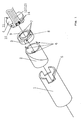
- FIG. 1 is an exploded perspective view of a preferred embodiment of the stator structure of a small three-phase brushless motor (hereafter miniature motor) in accordance with the present invention.
- This stator structure comprises a housing 1, a field coil 2, a tap wire guide 3, an end flange 4, and flexible substrates 12 and 13.
- the housing 1 has one end provided with cutouts 5.
- the field coil 2 includes tap wires 6.
- the tap wire guide 3 is provided with three grooves 7 and a raised step 8.
- the end flange 4 is shaped to double as a bearing and has an outer periphery provided with flat faces 10 and 11 whereon the flexible substrates 12 and 13 are respectively disposed fixedly in an identical structure.
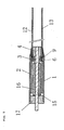
- the field coil 2 is fixedly disposed onto the inner wall of the housing 1, while the tap wire guide 3 is disposed onto one end of the field coil 2 from where the tap wires 6 are drawn out.
- a rotor comprising a magnet 16 and a shaft 15 penetrating a center thereof is fixedly disposed into the field coil 2 with a magnetic gap between and is held rotatably with a flange 17 and the end flange 4, which are fixedly disposed into the ends of the housing 1 and jointly double as a bearing.
- the flexible substrates 12 and 13, respectively, disposed onto the flat faces 10 and 11 of the end flange 4 are connected to the tap wires 6 exposed through the cutouts 5 via grooves 7 provided on the tap wire guide 3 and the space created by the raised step 8 so that a miniature motor in accordance with this invention will allow wiring connections on its outer periphery.
- This embodiment of a miniature motor has a star-connection of six tap wires, of which three neutral-point tap wires are entwined together by the guidance of the raised step 8, exposed through the cutouts 5 in the same manner as the other three tap wires, and solder-connected to power feed lands 14 on the two flexible substrates 12 and 13 disposed, respectively, onto the flat faces 10 and 11 of the end flange 4.
- Such a structure ensures that the power feed lands 14 have sufficiently large areas despite a decrease in the radial cross-sectional area of the motor due to the reduction in the diameter and allows minimization of the decrease in the amount of soldering for wiring connections and hence reduces the likelihood of problems such as wire breakage resulting from a reduced fixation strength of tap wires to the power feed lands. Moreover, such a structure does not involve bending of the flexible substrates 12 and 13, and therefore prevents the likelihood of wire breakage at the bend and saves the need of making allowance for the radius of the bend.
- the grooves 7 and the space created by the raised step 8 are filled with glue 9 or some other adhesive, and the solder-connection points connecting the tap wires 6 to the power feed lands 14 of the flexible substrates 12 and 13 are also fastened with the glue 9 or some other adhesive to protect the tap wires and the connection points from direct mechanical overloads and prevent wire breakage, thus ensuring an increased fixation strength of the wiring.
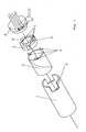
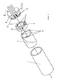
- FIGS. 2, 3, and 4 illustrate an embodiment of a stator structure that includes either only cutouts 5 provided on one end of a housing 1 or only flat faces 10 provided on the outer periphery of an end flange 4 to allow the connection of exposed tap wires to flexible substrates.
- FIG. 4 shows another embodiment of a stator structure wherein, while tap wires are connected to power feed lands 14a provided on flexible substrates 12 and 13 fixedly disposed onto flat faces 10 and 11 of an end flange 4, lead wires from the power supply side are connected to power feed lands 14b provided on the flexible substrates 12 and 13. Thus, lead wires can be used for connections to the power supply side.
- the present invention includes alternative embodiments of the miniature motor having the stator structures illustrated in FIGS. 2, 3, and 4.
Landscapes
- Engineering & Computer Science (AREA)
- Power Engineering (AREA)
- Insulation, Fastening Of Motor, Generator Windings (AREA)
- Motor Or Generator Frames (AREA)
Abstract
Description
- The present invention relates to a miniature brushless motor used in, for example, micro machinery and precision medical equipment.
- Conventional small cylindrical motors with an outer diameter of approximately 5 mm have been used as eccentrically weighted vibrating motors built in mobile communication devices, such as pagers, personal handy phone systems, and mobile phones, or as drive motors mounted in multi-motored precision equipment, such as office automation equipment, optical instruments, and radio-controlled model vehicles. Moreover, demands for minimized diameter and length are intensifying year by year due to the increasing demand in recent years for ultra-small motors primarily intended to be mounted in precision medical equipment, such as endoscopes or high-tech industrial equipment.
- However, the smaller a motor, the more mechanically difficult it is to route the wiring, such as power feed wires, from the power supply side. For ultra-small diameter motors, in particular with an outer diameter of 3 mm or smaller, it is critically important to optimize power feed wiring structure and the mounting location of each part in motor diameter reduction.
- FIGS. 6 and 7 show a motor wherein field
coil tap wires 20 of a cup-shaped or bell-shapedmultiphase field coil 19 are connected to power feed lands of aflexible substrate 22 viaconnection terminals 21. The strip-shaped protrusions of theflexible substrate 22 extending in the outer radial direction are bent to be accommodated in the concave portions ofcutouts 23 provided on one outer peripheral end of ahousing 18. Thus, elimination of any protrusion in the outer radial direction of the housing allows diameter minimization. The resulting advantages are significant especially for motors with an outer diameter of 2 mm or smaller (See Reference 1). - As illustrated in FIG 8, an approximate annular-
shaped mounting substrate 27 for holding aflexible substrate 25 having power feed lands for connecting fieldcoil tap wires 26 to an external power supply is fixedly disposed onto one end of afield coil 24, whileconcave grooves 28 are provided on the outer periphery of themounting substrate 27 to adhesively hold the fieldcoil tap wires 26. Thus, themounting substrate 27 doubles as a holder for the fieldcoil tap wires 26 and as a connection relay point to theflexible substrate 25, thereby reducing the likelihood of wire breakage, facilitating connection work to the external power supply, and improving assembly efficiency(See Reference 2). - Reference 1:
Japanese Patent Publication No. 2000-166157 - Reference 2:
Japanese Patent Publication No. 2003-284278 - Unfortunately, however, the related art described in the above-noted patent documents requires that a flexible substrate be bent and formed into a power feed route. Consequently, the likelihood of wire breakage at the bend is high. Moreover, the curvature (comer curvature) of the bend often results in variations of assembly precision, and therefore it was necessary to design the parts having such curvatures by taking the clearance between the parts into consideration. All these drawbacks are disadvantageous in reducing the size of motors.
- In a conventional flexible substrate, power feed lands are arranged in the cross-sectional direction of the motor for connection to the tap wires. Hence, a smaller-diameter motor has a reduced radial cross-sectional area and thereby smaller power feed lands, making assembly and other work more difficult. Smaller power feed lands also result in a proportionally reduced amount of soldering for wiring connections and a reduction in the fixation strength of tap wires, and hence a reduced reliability of the motor.
- Therefore, the object of the present invention is to provide a reliable miniature motor structure that solves the above-noted drawbacks, helps to secure sufficiently large power feed lands, and thereby allows for size reduction without the need to bend the flexible substrate.
- A first aspect of the present invention provides an inner rotor type miniature brushless motor comprising a housing, a field coil fixedly disposed onto an inner wall of the housing, an end flange fixedly disposed into one end of said housing, of which one end has tap wires of said field coil drawn out therefrom, cutouts provided on the one end of the housing fitted with the end flange providing a means for exposing the wires, and wiring substrates fixedly disposed onto an outer periphery of the end flange and connected to the tap wires.
- A second aspect of the present invention provides an inner rotor type miniature brushless motor comprising a housing, a field coil fixedly disposed onto an inner wall of the housing, an end flange fixedly disposed into one end of the housing having tap wires of the field coil drawn out and exposed therefrom, flat faces provided on an outer periphery of the end flange, and wiring substrates fixedly disposed onto the flat faces and connected to the tap wires.
- A third aspect of the present invention provides inner rotor type miniature brushless motor comprising a housing, a field coil fixedly disposed onto an inner wall of the housing, an end flange fixedly disposed into one end of the housing having tap wires of the field coil drawn out therefrom, cutouts provided on the one end of the housing fitted with the end flange providing a means for exposing the wires, flat faces provided on an outer periphery of the end flange, and wiring substrates fixedly disposed onto the flat faces and connected to the tap wires.
- A fourth aspect of the present invention preferably provides a miniature brushless motor according to any one of the first through third aspects, wherein an approximate annular-shaped tap wire guide made of an electrical insulation material is provided on one side of the field coil from where the tap wires are drawn out.
- A fifth aspect of the present invention preferably provides a miniature brushless motor according to the fourth aspect, wherein a raised step is provided on one side of the tap wire guide.
- A sixth aspect of the present invention preferably provides a miniature brushless motor according to the fifth aspect, wherein at least one groove is provided on an outer periphery of the tap wire guide.
- A seventh aspect of the present invention preferably provides a miniature brushless motor according to any one of the first through sixth aspects, wherein, of the tap wires of the field coil, neutral-point wires are entwined together for star-connection of the field coil to the wiring substrates.
- An eighth aspect of the present invention preferably provides a miniature brushless motor according to any one of the first through seventh aspects, wherein the end flange has an outer diameter not greater than that of the housing.
- A ninth aspect of the present invention preferably provides a miniature brushless motor according to any one of the first through eighth aspects, wherein a flange is fixedly disposed into the other end of the housing having the one end fixedly fitted with the end flange so that the end flange and/or the flange will double as a bearing.
- In a miniature brushless motor according to any one of the first through third aspects of the present invention, field coil tap wires are exposed through cutouts in a housing or an end-flange side end of a housing and connected to wiring substrates provided onto an outer periphery of an end flange so that, despite motor diameter reduction, the wiring substrates will retain power feed lands sufficiently large enough to accommodate a sufficient amount of solder for secure wiring connections without the need to reduce the amount of solder. Accordingly, problems, such as wire breakage from the reduced fixation strength of the tap wires to the power feed lands are prevented, thereby ensuring improved reliability of the motor.
- In a miniature brushless motor using a flexible substrate as a wiring substrate, the flexible substrate need not be bent and therefore can preclude the likelihood of wire breakage at the bend. Furthermore, because it is not necessary to design parts with curvatures and hence no variations in the precision of assembly due to the curvatures will result, it is possible to reduce clearances in between other parts, thereby allowing further size reduction of the motor.
- As set forth in the second and third aspects of the present invention, an end flange has an outer periphery provided with flat faces that allow a fixed disposition of wiring substrates in close contact with the end flange and thereby save the need to bend the wiring substrates around curved surface portions. Consequently, not only can detachment of the wiring substrates from the curved surface portions due to the bending stresses that may occur when the wiring substrates are bent, but also a decrease in fixation strength of a hard-to-bend substrate fixed on each curved surface portion due to a small contact area thereof be prevented, thereby ensuring improved reliability of the motor.
- In a miniature brushless motor according to the fourth aspect of the present invention, a field coil may have a tap wire side mounted with a tap wire guide that facilitates tap wire routing and hence improves assembly efficiency. Further, tap wires may be glued or otherwise fastened to the tap wire guide to strengthen and protect tap wire draw-out portions from likely wire breakage, thereby ensuring improved reliability of the motor.
- In a miniature brushless motor according to the fifth aspect of the present invention, a tap wire guide may be provided with a raised step for securing a space for tap wire routing. Further, the space may be filled with glue or some other adhesive to fasten the tap wire guide and the tap wires and thereby protect the tap wires from direct mechanical loads and prevent wire breakage, hence ensuring improved reliability of the motor. Furthermore, the raised step may prevent the tap wires from entering the inner diametrical portion of the tap wire guide and the extended portion thereof, and hence may prevent interferences between the tap wires and other parts.
- Moreover, as set forth in the sixth aspect of the present invention, a tap guide may be provided with grooves for accommodating tap wires. Furthermore, the grooves may be filled with glue or some other adhesive to fasten the tap wires and thereby prevent tap wire breakage, hence ensuring improved reliability of the motor.
- In a miniature brushless motor according to the seventh aspect of the present invention, neutral-point wires may be entwined and soldered or otherwise fastened to power feed lands on a wiring substrate for star-connection. Accordingly, such a miniature brushless motor may have fewer and larger power feed lands than miniature brushless motors of which tap wires are connected individually to power feed lands on a wiring substrate. In addition, a fewer number of connections may be required, thereby ensuring an improved assembling work efficiency.
- Moreover, in a miniature brushless motor according to the eighth aspect of the present invention, an end flange preferably has an outer diameter no greater than the outer diameter of a housing, thereby allowing minimization of the outer diameter of the miniature brushless motor.
- Furthermore, in a miniature brushless motor according to the ninth aspect of the present invention, a housing may have one end fixedly fitted with an end flange and the other end fixedly fitted with a flange so that the end flange and/or the flange will double as a bearing, allowing reduction of the number of intervening parts in radial directions and hence further size reduction.
- FIG. 1 is an exploded perspective view of a preferred embodiment of the stator structure of a small three-phase brushless motor (hereafter miniature motor) in accordance with the present invention. This stator structure comprises a
housing 1, afield coil 2, atap wire guide 3, anend flange 4, andflexible substrates housing 1 has one end provided withcutouts 5. Thefield coil 2 includestap wires 6. Thetap wire guide 3 is provided with threegrooves 7 and a raisedstep 8. It should be noted that theend flange 4 is shaped to double as a bearing and has an outer periphery provided withflat faces flexible substrates - As illustrated in FIG. 5, the
field coil 2 is fixedly disposed onto the inner wall of thehousing 1, while thetap wire guide 3 is disposed onto one end of thefield coil 2 from where thetap wires 6 are drawn out. Moreover, a rotor comprising amagnet 16 and ashaft 15 penetrating a center thereof is fixedly disposed into thefield coil 2 with a magnetic gap between and is held rotatably with aflange 17 and theend flange 4, which are fixedly disposed into the ends of thehousing 1 and jointly double as a bearing. Furthermore, theflexible substrates flat faces end flange 4 are connected to thetap wires 6 exposed through thecutouts 5 viagrooves 7 provided on thetap wire guide 3 and the space created by the raisedstep 8 so that a miniature motor in accordance with this invention will allow wiring connections on its outer periphery. - This embodiment of a miniature motor has a star-connection of six tap wires, of which three neutral-point tap wires are entwined together by the guidance of the raised
step 8, exposed through thecutouts 5 in the same manner as the other three tap wires, and solder-connected topower feed lands 14 on the twoflexible substrates flat faces end flange 4. - Such a structure ensures that the
power feed lands 14 have sufficiently large areas despite a decrease in the radial cross-sectional area of the motor due to the reduction in the diameter and allows minimization of the decrease in the amount of soldering for wiring connections and hence reduces the likelihood of problems such as wire breakage resulting from a reduced fixation strength of tap wires to the power feed lands. Moreover, such a structure does not involve bending of theflexible substrates - Moreover, the
grooves 7 and the space created by the raisedstep 8 are filled withglue 9 or some other adhesive, and the solder-connection points connecting thetap wires 6 to the power feed lands 14 of theflexible substrates glue 9 or some other adhesive to protect the tap wires and the connection points from direct mechanical overloads and prevent wire breakage, thus ensuring an increased fixation strength of the wiring. - While the above-described embodiment is one of the most preferable embodiments for the present invention, alternative stator structures in additional embodiments are shown in FIGS. 2, 3, and 4. FIGS 2 and 3 illustrate an embodiment of a stator structure that includes either
only cutouts 5 provided on one end of ahousing 1 or only flat faces 10 provided on the outer periphery of anend flange 4 to allow the connection of exposed tap wires to flexible substrates. Meanwhile, FIG. 4 shows another embodiment of a stator structure wherein, while tap wires are connected to power feed lands 14a provided onflexible substrates flat faces end flange 4, lead wires from the power supply side are connected to power feed lands 14b provided on theflexible substrates -
- FIG. 1 shows an exploded perspective view of a stator structure of a miniature brushless motor according to a first embodiment of the present invention.
- FIG. 2 shows an exploded perspective view of an alternative stator structure of a miniature brushless motor according to another embodiment of the present invention.
- FIG. 3 shows an exploded perspective view of another alternative stator structure of a miniature brushless motor according to yet another embodiment of the present invention.
- FIG. 4 shows an exploded perspective view of yet another alternative stator structure of miniature brushless motor according to a further alternative embodiment of the present invention.
- FIG. 5 shows a cross-sectional view of a miniature brushless motor according to the present invention.
- FIG. 6 shows a cross-sectional view of a conventional miniature motor.
- FIG. 7 shows an assembling perspective view of a power feeding portion for connection terminals of the conventional miniature motor.
- FIG. 8 shows a schematic perspective view of a stator including a field coil of another conventional miniature motor.
-
- 1, and 18
- Housing
- 2, 19, and 24
- Field coil
- 3
- Tap wire guide
- 4
- End flange
- 5 and 23
- Cutout
- 6
- Tap wire
- 7
- Groove
- 8
- Raised step
- 9
- Glue
- 10 and 11
- Flat face
- 14, 14a, and 14b
- Power feed land
- 12, 13, 22, and 25
- Flexible substrate
- 15
- Shaft
- 16
- Magnet
- 17
- Flange
- 20 and 26
- Field coil tap wire
- 21
- Connection terminal
- 27
- Mounting substrate
- 28
- Concave groove
Claims (9)
- An inner rotor type miniature brushless motor comprising:a housing,a field coil fixedly disposed onto an inner wall of said housing,an end flange fixedly disposed into one end of said housing, of which one end has tap wires of said field coil drawn out therefrom,cutouts provided on said one end of said housing fitted with said end flange and providing means for exposing said wires, andwiring substrates fixedly disposed onto an outer periphery of said end flange and connected to said tap wires.
- An inner rotor type miniature brushless motor comprising:a housing,a field coil fixedly disposed onto an inner wall of said housing,an end flange fixedly disposed into one end of said housing having tap wires of said field coil drawn out and exposed therefrom,flat faces provided on an outer periphery of said end flange, andwiring substrates fixedly disposed onto said flat faces and connected to said tap wires.
- An inner rotor type miniature brushless motor comprising:a housing,a field coil fixedly disposed onto an inner wall of said housing,an end flange fixedly disposed into one end of said housing having tap wires of said field coil drawn out therefrom,cutouts provided on said one end of said housing fitted with said end flange and providing means for exposing said wires,flat faces provided on an outer periphery of said end flange, andwiring substrates fixedly disposed onto said flat faces and connected to said tap wires.
- A miniature brushless motor according to any one of claims 1 through 3, wherein
an approximate annular-shaped tap wire guide made of an electrical insulation material is provided on one side of said field coil from where said tap wires are drawn out. - A miniature brushless motor according to claim 4, wherein
a raised step is provided on one side of said tap wire guide. - A miniature brushless motor according to claim 5, wherein
at least one groove is provided on an outer periphery of said tap wire guide. - A miniature brushless motor according to any one of claims 1 to 6, wherein,
of said tap wires of said field coil, neutral-point wires are entwined together for star-connection of said field coil to said wiring substrates. - A miniature brushless motor according to any one of claims 1 to 7, wherein
said end flange has an outer diameter not greater than that of said housing. - A miniature brushless motor according to any one of claims 1 to 8, wherein
a flange is fixedly disposed into the other end of said housing having said one end fixedly fitted with said end flange so that said end flange and/or said flange will double as a bearing.
Applications Claiming Priority (2)
| Application Number | Priority Date | Filing Date | Title |
|---|---|---|---|
| JP2004347868A JP4714812B2 (en) | 2004-11-30 | 2004-11-30 | Small brushless motor structure |
| PCT/JP2005/020441 WO2006059461A1 (en) | 2004-11-30 | 2005-11-08 | Small brushless motor structure |
Publications (3)
| Publication Number | Publication Date |
|---|---|
| EP1833142A1 true EP1833142A1 (en) | 2007-09-12 |
| EP1833142A4 EP1833142A4 (en) | 2010-06-30 |
| EP1833142B1 EP1833142B1 (en) | 2016-04-13 |
Family
ID=36564898
Family Applications (1)
| Application Number | Title | Priority Date | Filing Date |
|---|---|---|---|
| EP05806246.4A Ceased EP1833142B1 (en) | 2004-11-30 | 2005-11-08 | Small brushless motor structure |
Country Status (4)
| Country | Link |
|---|---|
| US (1) | US7579731B2 (en) |
| EP (1) | EP1833142B1 (en) |
| JP (1) | JP4714812B2 (en) |
| WO (1) | WO2006059461A1 (en) |
Cited By (1)
| Publication number | Priority date | Publication date | Assignee | Title |
|---|---|---|---|---|
| EP2597757A1 (en) * | 2011-11-24 | 2013-05-29 | Maxon Motor AG | Electric engine for high temperature applications |
Families Citing this family (5)
| Publication number | Priority date | Publication date | Assignee | Title |
|---|---|---|---|---|
| WO2008093689A1 (en) * | 2007-01-31 | 2008-08-07 | Namiki Seimitsu Houseki Kabushiki Kaisha | Motor and endoscope with the motor |
| FR2974968B1 (en) * | 2011-05-03 | 2013-07-05 | Aldebaran Robotics S A | PRINTED CIRCUIT FOR ENSURING THE CONNECTION OF AN ELECTRIC MOTOR AND AN ELECTRIC MOTOR COMPRISING THE PRINTED CIRCUIT |
| JP5658225B2 (en) * | 2012-12-26 | 2015-01-21 | 日本電産コパル株式会社 | Small motor |
| US11876429B2 (en) * | 2021-04-23 | 2024-01-16 | Nidec Corporation | Vibration motor and haptic device |
| JP7845898B2 (en) * | 2022-03-31 | 2026-04-14 | ニデック株式会社 | Vibration motors and haptic devices |
Family Cites Families (19)
| Publication number | Priority date | Publication date | Assignee | Title |
|---|---|---|---|---|
| US2874470A (en) * | 1954-05-28 | 1959-02-24 | James R Richards | High frequency dental tool |
| JPS6194529A (en) * | 1984-10-16 | 1986-05-13 | Matsushita Electric Ind Co Ltd | field assembly |
| JPS61180560A (en) * | 1985-02-01 | 1986-08-13 | Kangiyou Denki Kiki Kk | Dc brushless micromotor |
| US5240003A (en) * | 1989-10-16 | 1993-08-31 | Du-Med B.V. | Ultrasonic instrument with a micro motor having stator coils on a flexible circuit board |
| JP2911099B2 (en) * | 1993-06-30 | 1999-06-23 | ジェコー株式会社 | motor |
| US5442248A (en) * | 1994-04-11 | 1995-08-15 | Interroll Holding, A.G. | Motorized pulley with integral electrical connector |
| EP0711467A1 (en) * | 1994-05-26 | 1996-05-15 | Koninklijke Philips Electronics N.V. | Radial-field electric micromotor, cylindrical body for use in the micromotor, method of manufacturing the micromotor, and axial-field electric micromotor |
| US5481144A (en) * | 1994-06-03 | 1996-01-02 | Seagate Technology, Inc. | Wire guide and adhesive retaining ring for disc drive spindle motor |
| JP3029792B2 (en) * | 1995-12-28 | 2000-04-04 | 日本サーボ株式会社 | Multi-phase permanent magnet type rotating electric machine |
| JPH09271155A (en) * | 1996-03-29 | 1997-10-14 | Matsushita Electric Ind Co Ltd | How to install a cylindrical vibration generating motor |
| JPH1098846A (en) * | 1996-09-24 | 1998-04-14 | Shibaura Eng Works Co Ltd | Mold motor |
| JPH10229660A (en) * | 1997-02-14 | 1998-08-25 | Japan Servo Co Ltd | Inner rotor type small motor |
| JP3904227B2 (en) * | 1998-11-20 | 2007-04-11 | 並木精密宝石株式会社 | Power supply mechanism for small motors |
| JP2001016815A (en) * | 1999-06-30 | 2001-01-19 | Namiki Precision Jewel Co Ltd | Field coil tap wire connection structure for small motors |
| US6300739B1 (en) * | 1999-12-06 | 2001-10-09 | Hr Textron Inc. | Low cost limited angle torque DC brushless servomotor and method for fabricating thereof |
| IT1315419B1 (en) * | 2000-04-11 | 2003-02-10 | Coverco Spa | STRUCTURE OF SINGLE-PHASE MOTOR PARTICULARLY FOR SUBMERSIBLE PUMPS. |
| JP2003116247A (en) * | 2001-10-04 | 2003-04-18 | Mabuchi Motor Co Ltd | Small motor and manufacturing method thereof |
| JP4099568B2 (en) | 2002-03-20 | 2008-06-11 | 並木精密宝石株式会社 | DC brushless motor structure and assembly method |
| US6888271B2 (en) * | 2002-10-04 | 2005-05-03 | Visteon Global Technologies, Inc. | High power density alternator bobbin |
-
2004
- 2004-11-30 JP JP2004347868A patent/JP4714812B2/en not_active Expired - Lifetime
-
2005
- 2005-11-08 WO PCT/JP2005/020441 patent/WO2006059461A1/en not_active Ceased
- 2005-11-08 US US11/791,519 patent/US7579731B2/en not_active Expired - Fee Related
- 2005-11-08 EP EP05806246.4A patent/EP1833142B1/en not_active Ceased
Cited By (2)
| Publication number | Priority date | Publication date | Assignee | Title |
|---|---|---|---|---|
| EP2597757A1 (en) * | 2011-11-24 | 2013-05-29 | Maxon Motor AG | Electric engine for high temperature applications |
| US8946962B2 (en) | 2011-11-24 | 2015-02-03 | Maxon Motor Ag | Electric motor for high-temperature applications |
Also Published As
| Publication number | Publication date |
|---|---|
| US20070267934A1 (en) | 2007-11-22 |
| US7579731B2 (en) | 2009-08-25 |
| JP2006158138A (en) | 2006-06-15 |
| WO2006059461A1 (en) | 2006-06-08 |
| EP1833142B1 (en) | 2016-04-13 |
| EP1833142A4 (en) | 2010-06-30 |
| JP4714812B2 (en) | 2011-06-29 |
Similar Documents
| Publication | Publication Date | Title |
|---|---|---|
| US8172501B2 (en) | Counter-rotating axial-flow fax | |
| US7157823B2 (en) | Brushless vibration motor | |
| CN101188367A (en) | Armature and Motor | |
| US7800274B2 (en) | Thin stator, eccentric motor and axial air-gap brushless vibration motor equipped with the same | |
| US9755486B2 (en) | Motor | |
| US7579731B2 (en) | Miniature brushless motor structure | |
| US8648508B2 (en) | Small electric motor and method for producing a small electric motor | |
| US6617724B2 (en) | Non-circular, flat motor | |
| US20040051400A1 (en) | Low-profile, coreless motor | |
| JP3904227B2 (en) | Power supply mechanism for small motors | |
| US6836050B2 (en) | Terminal structures for motor with brush to connect motor to external circuit | |
| CN113472121A (en) | Motor | |
| KR100278894B1 (en) | Small motor | |
| JP2003189522A (en) | Small flat motor, small flat fan motor, forced air supply type air battery equipped with the motor, small flat vibration motor, and portable information device equipped with the motor | |
| EP1243062B1 (en) | Mirco-motor having a motor-base-plate containing stator-holding means and electrical terminals | |
| CN215682074U (en) | electric pump | |
| CN216872992U (en) | Motor and electric pump | |
| JP6660210B2 (en) | motor | |
| US20190078588A1 (en) | Blower device | |
| CN217445582U (en) | Substrate storage case and electric actuator | |
| JP4264245B2 (en) | Brushless motor | |
| US20260139690A1 (en) | Electric pump | |
| WO2002080335A1 (en) | Power feed mechanism | |
| JP2001016815A (en) | Field coil tap wire connection structure for small motors | |
| JP2008228472A (en) | Small motor device |
Legal Events
| Date | Code | Title | Description |
|---|---|---|---|
| PUAI | Public reference made under article 153(3) epc to a published international application that has entered the european phase |
Free format text: ORIGINAL CODE: 0009012 |
|
| 17P | Request for examination filed |
Effective date: 20070629 |
|
| AK | Designated contracting states |
Kind code of ref document: A1 Designated state(s): CH DE LI |
|
| DAX | Request for extension of the european patent (deleted) | ||
| RBV | Designated contracting states (corrected) |
Designated state(s): CH DE LI |
|
| A4 | Supplementary search report drawn up and despatched |
Effective date: 20100601 |
|
| 17Q | First examination report despatched |
Effective date: 20130213 |
|
| REG | Reference to a national code |
Ref country code: DE Ref legal event code: R079 Ref document number: 602005049017 Country of ref document: DE Free format text: PREVIOUS MAIN CLASS: H02K0005220000 Ipc: H02K0003470000 |
|
| GRAP | Despatch of communication of intention to grant a patent |
Free format text: ORIGINAL CODE: EPIDOSNIGR1 |
|
| RIC1 | Information provided on ipc code assigned before grant |
Ipc: H02K 5/22 20060101ALI20151001BHEP Ipc: H02K 3/47 20060101AFI20151001BHEP Ipc: H02K 5/167 20060101ALI20151001BHEP |
|
| INTG | Intention to grant announced |
Effective date: 20151030 |
|
| GRAS | Grant fee paid |
Free format text: ORIGINAL CODE: EPIDOSNIGR3 |
|
| GRAA | (expected) grant |
Free format text: ORIGINAL CODE: 0009210 |
|
| RAP1 | Party data changed (applicant data changed or rights of an application transferred) |
Owner name: NAMIKI SEIMITSU HOUSEKI KABUSHIKI KAISHA |
|
| AK | Designated contracting states |
Kind code of ref document: B1 Designated state(s): CH DE LI |
|
| REG | Reference to a national code |
Ref country code: CH Ref legal event code: NV Representative=s name: BUGNION S.A., CH Ref country code: CH Ref legal event code: EP |
|
| REG | Reference to a national code |
Ref country code: DE Ref legal event code: R096 Ref document number: 602005049017 Country of ref document: DE |
|
| REG | Reference to a national code |
Ref country code: DE Ref legal event code: R097 Ref document number: 602005049017 Country of ref document: DE |
|
| PGFP | Annual fee paid to national office [announced via postgrant information from national office to epo] |
Ref country code: DE Payment date: 20161121 Year of fee payment: 12 Ref country code: CH Payment date: 20161121 Year of fee payment: 12 |
|
| PLBE | No opposition filed within time limit |
Free format text: ORIGINAL CODE: 0009261 |
|
| STAA | Information on the status of an ep patent application or granted ep patent |
Free format text: STATUS: NO OPPOSITION FILED WITHIN TIME LIMIT |
|
| 26N | No opposition filed |
Effective date: 20170116 |
|
| REG | Reference to a national code |
Ref country code: DE Ref legal event code: R119 Ref document number: 602005049017 Country of ref document: DE |
|
| PG25 | Lapsed in a contracting state [announced via postgrant information from national office to epo] |
Ref country code: CH Free format text: LAPSE BECAUSE OF NON-PAYMENT OF DUE FEES Effective date: 20171130 Ref country code: LI Free format text: LAPSE BECAUSE OF NON-PAYMENT OF DUE FEES Effective date: 20171130 |
|
| PG25 | Lapsed in a contracting state [announced via postgrant information from national office to epo] |
Ref country code: DE Free format text: LAPSE BECAUSE OF NON-PAYMENT OF DUE FEES Effective date: 20180602 |