EP1832824A1 - Forced convection heat transfer apparatus - Google Patents
Forced convection heat transfer apparatus Download PDFInfo
- Publication number
- EP1832824A1 EP1832824A1 EP05811623A EP05811623A EP1832824A1 EP 1832824 A1 EP1832824 A1 EP 1832824A1 EP 05811623 A EP05811623 A EP 05811623A EP 05811623 A EP05811623 A EP 05811623A EP 1832824 A1 EP1832824 A1 EP 1832824A1
- Authority
- EP
- European Patent Office
- Prior art keywords
- heat
- flow path
- fluid flow
- heat transfer
- transfer apparatus
- Prior art date
- Legal status (The legal status is an assumption and is not a legal conclusion. Google has not performed a legal analysis and makes no representation as to the accuracy of the status listed.)
- Granted
Links
Images


Classifications
-
- F—MECHANICAL ENGINEERING; LIGHTING; HEATING; WEAPONS; BLASTING
- F28—HEAT EXCHANGE IN GENERAL
- F28D—HEAT-EXCHANGE APPARATUS, NOT PROVIDED FOR IN ANOTHER SUBCLASS, IN WHICH THE HEAT-EXCHANGE MEDIA DO NOT COME INTO DIRECT CONTACT
- F28D15/00—Heat-exchange apparatus with the intermediate heat-transfer medium in closed tubes passing into or through the conduit walls ; Heat-exchange apparatus employing intermediate heat-transfer medium or bodies
-
- H—ELECTRICITY
- H02—GENERATION; CONVERSION OR DISTRIBUTION OF ELECTRIC POWER
- H02K—DYNAMO-ELECTRIC MACHINES
- H02K44/00—Machines in which the dynamo-electric interaction between a plasma or flow of conductive liquid or of fluid-borne conductive or magnetic particles and a coil system or magnetic field converts energy of mass flow into electrical energy or vice versa
- H02K44/02—Electrodynamic pumps
- H02K44/06—Induction pumps
-
- H—ELECTRICITY
- H10—SEMICONDUCTOR DEVICES; ELECTRIC SOLID-STATE DEVICES NOT OTHERWISE PROVIDED FOR
- H10W—GENERIC PACKAGES, INTERCONNECTIONS, CONNECTORS OR OTHER CONSTRUCTIONAL DETAILS OF DEVICES COVERED BY CLASS H10
- H10W40/00—Arrangements for thermal protection or thermal control
- H10W40/40—Arrangements for thermal protection or thermal control involving heat exchange by flowing fluids
- H10W40/47—Arrangements for thermal protection or thermal control involving heat exchange by flowing fluids by flowing liquids, e.g. forced water cooling
-
- F—MECHANICAL ENGINEERING; LIGHTING; HEATING; WEAPONS; BLASTING
- F28—HEAT EXCHANGE IN GENERAL
- F28D—HEAT-EXCHANGE APPARATUS, NOT PROVIDED FOR IN ANOTHER SUBCLASS, IN WHICH THE HEAT-EXCHANGE MEDIA DO NOT COME INTO DIRECT CONTACT
- F28D21/00—Heat-exchange apparatus not covered by any of the groups F28D1/00 - F28D20/00
- F28D2021/0019—Other heat exchangers for particular applications; Heat exchange systems not otherwise provided for
- F28D2021/0028—Other heat exchangers for particular applications; Heat exchange systems not otherwise provided for for cooling heat generating elements, e.g. for cooling electronic components or electric devices
- F28D2021/0029—Heat sinks
-
- F—MECHANICAL ENGINEERING; LIGHTING; HEATING; WEAPONS; BLASTING
- F28—HEAT EXCHANGE IN GENERAL
- F28F—DETAILS OF HEAT-EXCHANGE AND HEAT-TRANSFER APPARATUS, OF GENERAL APPLICATION
- F28F2250/00—Arrangements for modifying the flow of the heat exchange media, e.g. flow guiding means; Particular flow patterns
- F28F2250/08—Fluid driving means, e.g. pumps, fans
Definitions
- the present invention relates to a magnetic element for heat transfer. Specifically it relates to a heat transfer apparatus comprising a fluid flow path through which a magnetic fluid is circulated and a rotatable magnet unit for circulating the magnetic fluid by applying a varying magnetic fluid.
- a large quantity of heat can be transferred based on forced convection by the apparatus even when the temperature differential is small between the heat receiving and discharging sections by rotating the magnet unit along and beside the fluid flow path to obtain a circulating velocity of the magnetic fluid proportionally to the rotational speed of the magnet unit.
- JP 2003/232596 discloses a heat transfer system of a forced convection type by circulating a magnetic fluid in a magnetic field. This system does not require electrical power and allows to construct in a simple structure without occupying a large space.
- the heat transfer efficiency based on the spontaneous convection has a certain limit no matter how the performance of magnetic fluid is improved. Accordingly, it is difficult to develop a magnetic element capable of transferring a large quantity of heat.
- a temperature differential of at least 10°C is generally required in the working environment to transfer the heat by the spontaneous convection.
- the object of the present invention is to provide a heat transfer apparatus utilizing forced convection which can transfer a large quantity of heat efficiently even when the heat differential is small.
- the apparatus comprises a fluid flow path through which a magnetic fluid is circulated and a rotatable magnet unit disposed along and beside the fluid flow path for magnetically driving a magnetic fluid at a flow rate proportional to the rotational speed of the magnet. Because of forced convection, a large quantity of heat can be transferred even when the heat differential is small.
- the magnetic fluid is driven to circulate through the fluid flow path under the influence of rotating magnetic field created by the rotation of the magnet unit in such a way that a large quantity of heat may be transferred even when the temperature differential is small.
- the rotatable magnet unit disposed alongside the fluid flow path located in the heat discharge section.
- the magnet unit preferably has a rod shape and is rotationally driven about an axis by an electrical motor coaxially connected thereto.
- an electrical motor coaxially connected thereto.
- a portion of the fluid flow path to be disposed in the rotational area of the magnet is semi-circular in shape and circumferentially extends through at least 180 degree about the rotational axis.
- the magnetic fluid is circulated through the fluid flow path in the rotational direction of the magnet unit to transfer the heat.
- a rotating fan is co-axially connected to the magnet unit and rotated therewith by an electrical motor.
- the heat transfer efficiency of the circulating magnetic fluid may be further enhanced by blowing air by the fan to the heat discharge portion of the fluid flow path.
- the heat transfer apparatus shown in Fig. 1 comprises a heat discharger section (1) a heat receiver section (2), a fluid flow path (3) for circulating a magnetic fluid between the heat discharger section (1) and the heat receiver section (2), a pair of rod-shaped magnets (4,5) rotatably disposed alongside the fluid flow path (3), and a rotational shaft (6) to which the magnet pair is rotatably connected at the center thereof.
- the magnet pair is rotated by pneumatic, hydraulic or electric power to circulate the magnetic fluid counterclockwise under the influence of a varying magnetic field through the fluid flow path (3) so that a quantity of heat is transferred from the heat receiving section (2) to the heat discharging section (1), for example, for melting snow or generating electric power.
- the rotatable magnet unit in this embodiment is shown to be in a rod shape but it will be appreciated that other configurations may be employed as well provided that a sufficient gradient is created in the magnetic field.
- the magnetic fluid used in this embodiment refers to a dispersion of a magnet powder consisting of a divalent transition metal element and iron oxide having an average particle size less than 30 ⁇ m, preferably 1-10 ⁇ m in a fluid medium.
- the magnet particles have been treated with a surfactant to exert a repulsive force to each other when dispersed in a fluid medium such as a paramagnetic gas or liquid.
- the heat discharging section (1) is preferably constructed from a magnetism-permeable material such as aluminum.
- a ferromagnetic metal such as iron is not suitable due to possible magnetization which may inferer with the rotation of the magnet unit.
- the connection portions of the fluid flow path may be constructed from a metal tube taking its durability into consideration.
- heat transfer may be accomplished with a relatively simple structure between the above and beneath the ground either for warming the room during the winter or for cooling the room during the summer. It find use also in the heat equalization between panels of an artificial satellite or similar heat transfer systems requiring a very small amount of rotating power.
- the embodiment shown in Fig. 2 differs from the embodiment shown in Fig. 1 in that the flow path (3) of the magnetic fluid has an enlarged fluid flow portion (7) in the magnetic field of the rotatable magnet unit.
- the enlarged fluid flow portion (7) is positioned in the magnetic field of the rotating magnet unit (4,5) on the upstream side (right hand side in the drawing) of the flow of magnetic fluid so that a large volume of the magnetic fluid is retained in the enlarged fluid flow portion (7).
- the length of the fluid flow path (3) in the heat discharging section (1) is greater on the upstream side (right hand side in the drawing) of the rotating magnet element (4,5) than on the downstream side (left hand side in the drawing) of the rotating magnet unit (4,5).
- the magnetic fluid is cooled before reaching the enlarged fluid flow portion (7) and exposed to the line of magnetic force there with increased magnetization.
- the magnetic fluid is magnetically conveyed counterclockwise by the rotating magnet unit to transfer heat in an efficient manner.
- the third embodiment of the apparatus of the present invention differs from the apparatus shown in Fig. 2 in that the fluid flow path (3) is detachable at the inlet to the heat receiving section (2) by providing respective connecting ends of the flow path (3) with magnetic connector members (4a, 5a) having opposed polarity. Since the temperature of the magnetic fluid in the heat receiving section (2) is higher than the temperature of magnetic fluid in the fluid flow path upstream of the magnetic connector (5a), magnetic convection will be generated in the same direction as the circulating magnetic fluid to assist fluid flow through the flow path (3). Detachable connection of the fluid flow circuit (3) also allows easy infusion and withdrawal of the magnetic fluid.
- the apparatus of this embodiment additionally comprises a fan (9) and a heat radiator (10) associated with the fluid flow path (3) within the heat discharging section (1).
- the fan (9) is mounted on the shaft (6) coaxially with the rotatable magnet unit (4,5).
- the magnet unit (4,5) and the fan (9) are mounted on the same shalf (6) to rotate synchronously.
- a plurality of electromagnet elements (8) are distributed on the fan blades as shown and a controller (not shown) sequentially activates a series of electromagnet elements (8) to rotate the fan (8) and the magnet element (4,5) in the manner as is well known in the art.
- a heat radiator (10) is provided in the heat discharging section (1) for discharging heat via radiation.
- the fun (9) functions to cool the fluid flow path (3) and thus the magnetic fluid therein in the vicinity of the rotating magnet unit (4,5). It will be appreciated, however, that other blowing means may be used as well.
- an apparatus having heat transfer and discharge means may be provided with very simple and compact design for use, for example, as cooling means of computer CPU and other devices.
- the apparatus may be installed in a wide variety of locations by connecting between the heat receiving section (1) and the heat discharging section (2) by a flexible tubular member.
- the heat transfer apparatus of the present invention may find use in the recovery of waste heat generated in electric power plants or energy conversion plants of another type in environment-friendly manner.
- Other usages which can be envisaged include a heat transfer element utilizing earth heat, a heat equalizer of satellite panels, cooling means for electronic devices and the like.
Landscapes
- Engineering & Computer Science (AREA)
- Physics & Mathematics (AREA)
- Thermal Sciences (AREA)
- Mechanical Engineering (AREA)
- General Engineering & Computer Science (AREA)
- Power Engineering (AREA)
- Physical Or Chemical Processes And Apparatus (AREA)
- Hard Magnetic Materials (AREA)
Abstract
Description
- The present invention relates to a magnetic element for heat transfer. Specifically it relates to a heat transfer apparatus comprising a fluid flow path through which a magnetic fluid is circulated and a rotatable magnet unit for circulating the magnetic fluid by applying a varying magnetic fluid. A large quantity of heat can be transferred based on forced convection by the apparatus even when the temperature differential is small between the heat receiving and discharging sections by rotating the magnet unit along and beside the fluid flow path to obtain a circulating velocity of the magnetic fluid proportionally to the rotational speed of the magnet unit.
- It is well known to transfer a large quantity of heat by circulating fluid through a closed loop using a pump.
JP 2003/232596 - Developments in the technology concerning the synthesis and micronization of metal oxide-ferromagnetic materials in recent years have remarkably improved the efficiency of convectional heat transfer by the magnetic fluid.
- However, the heat transfer efficiency based on the spontaneous convection has a certain limit no matter how the performance of magnetic fluid is improved. Accordingly, it is difficult to develop a magnetic element capable of transferring a large quantity of heat.
- Since the efficiency of heat transfer by the convention decreases as the temperature differential decreases, a temperature differential of at least 10°C is generally required in the working environment to transfer the heat by the spontaneous convection.
- The object of the present invention is to provide a heat transfer apparatus utilizing forced convection which can transfer a large quantity of heat efficiently even when the heat differential is small.
- In order to achieve the foregoing object, the apparatus comprises a fluid flow path through which a magnetic fluid is circulated and a rotatable magnet unit disposed along and beside the fluid flow path for magnetically driving a magnetic fluid at a flow rate proportional to the rotational speed of the magnet. Because of forced convection, a large quantity of heat can be transferred even when the heat differential is small.
- In the apparatus of the present invention, the magnetic fluid is driven to circulate through the fluid flow path under the influence of rotating magnetic field created by the rotation of the magnet unit in such a way that a large quantity of heat may be transferred even when the temperature differential is small.
-
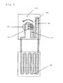
- Fig. 1 is a schematic plan view of the first embodiment of the heat transfer apparatus according to the present invention.
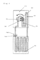
- Fig. 2 is a schematic plan view of the second embodiment of the heat transfer apparatus according to the present invention.
- Fig. 3 is a schematic plan view of the third embodiment of the heat transfer apparatus according to the present invention.
- Fig. 4 is a schematic plan view of the fourth embodiment of the heat transfer apparatus according to the present invention.
- The rotatable magnet unit disposed alongside the fluid flow path located in the heat discharge section. The magnet unit preferably has a rod shape and is rotationally driven about an axis by an electrical motor coaxially connected thereto. Thus the magnetic field in the rotational area of the magnet unit varies in strength with the angle of rotation of the magnet unit.
- A portion of the fluid flow path to be disposed in the rotational area of the magnet is semi-circular in shape and circumferentially extends through at least 180 degree about the rotational axis. Thus the magnetic fluid is circulated through the fluid flow path in the rotational direction of the magnet unit to transfer the heat.
- In another embodiment a rotating fan is co-axially connected to the magnet unit and rotated therewith by an electrical motor. The heat transfer efficiency of the circulating magnetic fluid may be further enhanced by blowing air by the fan to the heat discharge portion of the fluid flow path.
- Now the first embodiment of the heat transfer apparatus according to the present invention will be described in further detail with reference to Fig. 1.
- The heat transfer apparatus shown in Fig. 1 comprises a heat discharger section (1) a heat receiver section (2), a fluid flow path (3) for circulating a magnetic fluid between the heat discharger section (1) and the heat receiver section (2), a pair of rod-shaped magnets (4,5) rotatably disposed alongside the fluid flow path (3), and a rotational shaft (6) to which the magnet pair is rotatably connected at the center thereof.
- In the embodiment shown in Fig. 1, the magnet pair is rotated by pneumatic, hydraulic or electric power to circulate the magnetic fluid counterclockwise under the influence of a varying magnetic field through the fluid flow path (3) so that a quantity of heat is transferred from the heat receiving section (2) to the heat discharging section (1), for example, for melting snow or generating electric power. The rotatable magnet unit in this embodiment is shown to be in a rod shape but it will be appreciated that other configurations may be employed as well provided that a sufficient gradient is created in the magnetic field.
- The magnetic fluid used in this embodiment refers to a dispersion of a magnet powder consisting of a divalent transition metal element and iron oxide having an average particle size less than 30 µm, preferably 1-10 µm in a fluid medium. The magnet particles have been treated with a surfactant to exert a repulsive force to each other when dispersed in a fluid medium such as a paramagnetic gas or liquid.
- The heat discharging section (1) is preferably constructed from a magnetism-permeable material such as aluminum. A ferromagnetic metal such as iron is not suitable due to possible magnetization which may inferer with the rotation of the magnet unit. It also preferable to connect between the heat discharging section and the heat receiving section (2) with the fluid flow path (3) made of a flexible plastic tube. However, the connection portions of the fluid flow path may be constructed from a metal tube taking its durability into consideration.
- According to this embodiment, heat transfer may be accomplished with a relatively simple structure between the above and beneath the ground either for warming the room during the winter or for cooling the room during the summer. It find use also in the heat equalization between panels of an artificial satellite or similar heat transfer systems requiring a very small amount of rotating power.
- Now the second embodiment of the heat transfer apparatus according to the present invention will be described in greater detail with reference to Fig. 2. The embodiment shown in Fig. 2 differs from the embodiment shown in Fig. 1 in that the flow path (3) of the magnetic fluid has an enlarged fluid flow portion (7) in the magnetic field of the rotatable magnet unit. The enlarged fluid flow portion (7) is positioned in the magnetic field of the rotating magnet unit (4,5) on the upstream side (right hand side in the drawing) of the flow of magnetic fluid so that a large volume of the magnetic fluid is retained in the enlarged fluid flow portion (7).
- In addition, the length of the fluid flow path (3) in the heat discharging section (1) is greater on the upstream side (right hand side in the drawing) of the rotating magnet element (4,5) than on the downstream side (left hand side in the drawing) of the rotating magnet unit (4,5). As a result, the magnetic fluid is cooled before reaching the enlarged fluid flow portion (7) and exposed to the line of magnetic force there with increased magnetization. Thus, the magnetic fluid is magnetically conveyed counterclockwise by the rotating magnet unit to transfer heat in an efficient manner.
- Referring to Fig. 3, the third embodiment of the apparatus of the present invention is shown. The apparatus of this embodiment differs from the apparatus shown in Fig. 2 in that the fluid flow path (3) is detachable at the inlet to the heat receiving section (2) by providing respective connecting ends of the flow path (3) with magnetic connector members (4a, 5a) having opposed polarity. Since the temperature of the magnetic fluid in the heat receiving section (2) is higher than the temperature of magnetic fluid in the fluid flow path upstream of the magnetic connector (5a), magnetic convection will be generated in the same direction as the circulating magnetic fluid to assist fluid flow through the flow path (3). Detachable connection of the fluid flow circuit (3) also allows easy infusion and withdrawal of the magnetic fluid.
- Referring to Fig. 4, the fourth embodiment of the apparatus of the present invention is shown. The apparatus of this embodiment additionally comprises a fan (9) and a heat radiator (10) associated with the fluid flow path (3) within the heat discharging section (1). The fan (9) is mounted on the shaft (6) coaxially with the rotatable magnet unit (4,5). In this embodiment, the magnet unit (4,5) and the fan (9) are mounted on the same shalf (6) to rotate synchronously. A plurality of electromagnet elements (8) are distributed on the fan blades as shown and a controller (not shown) sequentially activates a series of electromagnet elements (8) to rotate the fan (8) and the magnet element (4,5) in the manner as is well known in the art.
- In addition to the fan (9), a heat radiator (10) is provided in the heat discharging section (1) for discharging heat via radiation. The fun (9) functions to cool the fluid flow path (3) and thus the magnetic fluid therein in the vicinity of the rotating magnet unit (4,5). It will be appreciated, however, that other blowing means may be used as well.
- According to the present invention, an apparatus having heat transfer and discharge means may be provided with very simple and compact design for use, for example, as cooling means of computer CPU and other devices. In addition, the apparatus may be installed in a wide variety of locations by connecting between the heat receiving section (1) and the heat discharging section (2) by a flexible tubular member.
- The heat transfer apparatus of the present invention may find use in the recovery of waste heat generated in electric power plants or energy conversion plants of another type in environment-friendly manner. Other usages which can be envisaged include a heat transfer element utilizing earth heat, a heat equalizer of satellite panels, cooling means for electronic devices and the like.
Claims (6)
- A heat transfer apparatus of a forced convection type comprising a heat receiving section, a heat discharging section, a fluid flow path for circulating a magnetic fluid between said heat receiving and said heat discharging sections, and a rotatable magnet unit disposed alongside at least a portion of said fluid flow path in said heat receiving section, wherein said rotatable magnet unit applies a varying magnetic force to said magnetic fluid in said portion of the fluid flow path in said heat receiving section.
- The heat transfer apparatus according to claim 1, wherein said fluid flow path in said heat receiving section has different inner volumes between the upstream side and the downstream side of the rotating area of said magnet unit, and wherein the inner volume of said fluid flow path on said upstream side is greater than the inner volume of said fluid flow path on said downstream side.
- The heat transfer apparatus according to claim 1, wherein said fluid flow path is formed in a closed loop by connecting both ends of said fluid path in said heat receiving section to respective ends of said fluid path in said heat discharging section with respective connecting conduits.
- The heat transfer apparatus according to claim 3, wherein at least one of said connecting conduit carries a first magnet of the first polarity for attaching the conduit to the fluid flow path in said heat receiving section carrying a second magnet of the second polarity.
- The heat transfer apparatus according to claim 1, wherein said rotatable magnet unit is coaxially connected to air blowing means which is rotated synchronously or non-synchronously with the magnet unit.
- The heat transfer apparatus according to claim 5, wherein said air blowing means is rotated by activating a plurating of electromagnets associated therewith.
Applications Claiming Priority (2)
| Application Number | Priority Date | Filing Date | Title |
|---|---|---|---|
| JP2004350762 | 2004-12-03 | ||
| PCT/JP2005/021957 WO2006059623A1 (en) | 2004-12-03 | 2005-11-30 | Forced convection heat transfer apparatus |
Publications (3)
| Publication Number | Publication Date |
|---|---|
| EP1832824A1 true EP1832824A1 (en) | 2007-09-12 |
| EP1832824A4 EP1832824A4 (en) | 2012-04-25 |
| EP1832824B1 EP1832824B1 (en) | 2013-07-03 |
Family
ID=36565057
Family Applications (1)
| Application Number | Title | Priority Date | Filing Date |
|---|---|---|---|
| EP05811623.7A Expired - Lifetime EP1832824B1 (en) | 2004-12-03 | 2005-11-30 | Forced convection heat transfer apparatus |
Country Status (4)
| Country | Link |
|---|---|
| US (1) | US8028745B2 (en) |
| EP (1) | EP1832824B1 (en) |
| JP (1) | JP4336902B2 (en) |
| WO (1) | WO2006059623A1 (en) |
Cited By (1)
| Publication number | Priority date | Publication date | Assignee | Title |
|---|---|---|---|---|
| WO2010023381A3 (en) * | 2008-08-26 | 2010-04-22 | Cooltech Applications S.A.S. | Heat generator using magnetocaloric material |
Families Citing this family (8)
| Publication number | Priority date | Publication date | Assignee | Title |
|---|---|---|---|---|
| JP5245172B2 (en) * | 2007-11-21 | 2013-07-24 | 独立行政法人日本原子力研究開発機構 | Magnetic field rotating electromagnetic pump with leveling magnetic field formation mechanism |
| US20110186266A1 (en) * | 2010-02-01 | 2011-08-04 | Suna Display Co. | Heat transfer device with anisotropic thermal conducting structures |
| KR20130025635A (en) * | 2011-09-02 | 2013-03-12 | 삼성전기주식회사 | Cooling unit |
| JP5764465B2 (en) * | 2011-10-31 | 2015-08-19 | セイコーインスツル株式会社 | Thermoelectric power generation portable device and power generation control method for thermoelectric power generation portable device |
| JP5764464B2 (en) * | 2011-10-31 | 2015-08-19 | セイコーインスツル株式会社 | Portable thermoelectric generator |
| JP6120320B2 (en) * | 2013-06-21 | 2017-04-26 | 国立研究開発法人産業技術総合研究所 | Fluid drive device for cooling circulation of heat source using magnetic fluid |
| JP7693326B2 (en) | 2021-02-15 | 2025-06-17 | キヤノン株式会社 | Imaging device having a magnetic fluid heat transport system |
| JP7012404B1 (en) | 2021-11-30 | 2022-01-28 | Btsジャパン株式会社 | Cooling device for electronic components |
Family Cites Families (8)
| Publication number | Priority date | Publication date | Assignee | Title |
|---|---|---|---|---|
| US4519447A (en) * | 1980-08-04 | 1985-05-28 | Fine Particle Technology Corporation | Substrate cooling |
| JPH0378605U (en) | 1989-12-05 | 1991-08-09 | ||
| JPH03229493A (en) * | 1990-02-05 | 1991-10-11 | Fujitsu Ltd | Immersion cooling structure |
| JPH0814779A (en) * | 1994-06-30 | 1996-01-19 | Sharp Corp | heat pipe |
| US6019165A (en) * | 1998-05-18 | 2000-02-01 | Batchelder; John Samuel | Heat exchange apparatus |
| JP3078605U (en) | 2000-12-27 | 2001-07-10 | 敬之 住友 | Pipe fitting and faucet-mounted shower device |
| US6648064B1 (en) * | 2002-11-14 | 2003-11-18 | Lsi Logic Corporation | Active heat sink |
| JP2004254437A (en) * | 2003-02-20 | 2004-09-09 | Yamaha Motor Co Ltd | Cooling device using magnetic fluid |
-
2005
- 2005-11-30 EP EP05811623.7A patent/EP1832824B1/en not_active Expired - Lifetime
- 2005-11-30 JP JP2006547962A patent/JP4336902B2/en not_active Expired - Fee Related
- 2005-11-30 WO PCT/JP2005/021957 patent/WO2006059623A1/en not_active Ceased
- 2005-11-30 US US11/720,725 patent/US8028745B2/en not_active Expired - Fee Related
Cited By (1)
| Publication number | Priority date | Publication date | Assignee | Title |
|---|---|---|---|---|
| WO2010023381A3 (en) * | 2008-08-26 | 2010-04-22 | Cooltech Applications S.A.S. | Heat generator using magnetocaloric material |
Also Published As
| Publication number | Publication date |
|---|---|
| US20080277100A1 (en) | 2008-11-13 |
| EP1832824B1 (en) | 2013-07-03 |
| EP1832824A4 (en) | 2012-04-25 |
| JPWO2006059623A1 (en) | 2008-06-05 |
| WO2006059623A1 (en) | 2006-06-08 |
| JP4336902B2 (en) | 2009-09-30 |
| US8028745B2 (en) | 2011-10-04 |
Similar Documents
| Publication | Publication Date | Title |
|---|---|---|
| US7339144B2 (en) | Magnetic heat generation | |
| US7420144B2 (en) | Controlled torque magnetic heat generation | |
| EP1832824B1 (en) | Forced convection heat transfer apparatus | |
| US10326343B2 (en) | Magnetic-drive axial-flow fluid displacement pump and turbine | |
| CN102759216B (en) | Magnetic heat pump system | |
| CN1326239C (en) | Method and device of integrated fan pump cooling assembly | |
| CN108028079A (en) | Pneumatic motor assembly, uses the method for the flow sensing system and operation Pneumatic motor assembly of the Pneumatic motor assembly | |
| US8283615B1 (en) | Permanent magnet air heater | |
| EP1832828A1 (en) | Magnetic convection heat circulation pump | |
| CN102477971A (en) | Cold/hot row with in-line fluid actuated external fluid pump | |
| EP0814269A2 (en) | Air moving device | |
| CN218266374U (en) | Disc type magnetic force shield pump driven by permanent magnet synchronous motor of integrated controller | |
| JP2001077571A (en) | Cooling system | |
| CN115149721A (en) | Disc type magnetic force shield pump driven by permanent magnet synchronous motor of integrated controller | |
| Paszota | Energy losses in hydrostatic drive: Drive investigation method compatible with diagram of power increase opposite to the direction of power flow | |
| CN1766463A (en) | A natural convection heat exchange type room temperature magnetic refrigeration device | |
| CN103423913B (en) | Buildings and their heat exchange systems | |
| CN109471512A (en) | Cooling heat exchange system and notebook computer | |
| Bozkir et al. | The Effect of Permanent Magnet Location on The Performance of Ferrofluid Based Spncml | |
| CN2195729Y (en) | Magnetohydrodynamic air warming machine | |
| JP6120320B2 (en) | Fluid drive device for cooling circulation of heat source using magnetic fluid | |
| Ponnappan et al. | Venturi flow cooling concept for high heat flux applications. | |
| CN106568229A (en) | Novel electromagnetic propulsion magneto-rheological fluid refrigerating device based on magnetocaloric effect | |
| AU2006201797A1 (en) | Enhancing the immune response to an antigen by presensitizing with an inducing agent prior to immunizing with the inducing agent and the antigen |
Legal Events
| Date | Code | Title | Description |
|---|---|---|---|
| PUAI | Public reference made under article 153(3) epc to a published international application that has entered the european phase |
Free format text: ORIGINAL CODE: 0009012 |
|
| 17P | Request for examination filed |
Effective date: 20070702 |
|
| AK | Designated contracting states |
Kind code of ref document: A1 Designated state(s): AT BE BG CH CY CZ DE DK EE ES FI FR GB GR HU IE IS IT LI LT LU LV MC NL PL PT RO SE SI SK TR |
|
| DAX | Request for extension of the european patent (deleted) | ||
| A4 | Supplementary search report drawn up and despatched |
Effective date: 20120328 |
|
| RIC1 | Information provided on ipc code assigned before grant |
Ipc: H01L 23/473 20060101ALI20120322BHEP Ipc: F25D 9/00 20060101AFI20120322BHEP Ipc: H02K 44/06 20060101ALI20120322BHEP Ipc: F28D 15/00 20060101ALI20120322BHEP |
|
| GRAP | Despatch of communication of intention to grant a patent |
Free format text: ORIGINAL CODE: EPIDOSNIGR1 |
|
| GRAS | Grant fee paid |
Free format text: ORIGINAL CODE: EPIDOSNIGR3 |
|
| GRAA | (expected) grant |
Free format text: ORIGINAL CODE: 0009210 |
|
| AK | Designated contracting states |
Kind code of ref document: B1 Designated state(s): AT BE BG CH CY CZ DE DK EE ES FI FR GB GR HU IE IS IT LI LT LU LV MC NL PL PT RO SE SI SK TR |
|
| REG | Reference to a national code |
Ref country code: GB Ref legal event code: FG4D |
|
| REG | Reference to a national code |
Ref country code: AT Ref legal event code: REF Ref document number: 620014 Country of ref document: AT Kind code of ref document: T Effective date: 20130715 Ref country code: CH Ref legal event code: EP |
|
| REG | Reference to a national code |
Ref country code: IE Ref legal event code: FG4D |
|
| REG | Reference to a national code |
Ref country code: DE Ref legal event code: R096 Ref document number: 602005040288 Country of ref document: DE Effective date: 20130829 |
|
| REG | Reference to a national code |
Ref country code: SE Ref legal event code: TRGR |
|
| PG25 | Lapsed in a contracting state [announced via postgrant information from national office to epo] |
Ref country code: SI Free format text: LAPSE BECAUSE OF FAILURE TO SUBMIT A TRANSLATION OF THE DESCRIPTION OR TO PAY THE FEE WITHIN THE PRESCRIBED TIME-LIMIT Effective date: 20130703 |
|
| REG | Reference to a national code |
Ref country code: AT Ref legal event code: MK05 Ref document number: 620014 Country of ref document: AT Kind code of ref document: T Effective date: 20130703 |
|
| REG | Reference to a national code |
Ref country code: NL Ref legal event code: VDEP Effective date: 20130703 |
|
| REG | Reference to a national code |
Ref country code: LT Ref legal event code: MG4D |
|
| PG25 | Lapsed in a contracting state [announced via postgrant information from national office to epo] |
Ref country code: BE Free format text: LAPSE BECAUSE OF FAILURE TO SUBMIT A TRANSLATION OF THE DESCRIPTION OR TO PAY THE FEE WITHIN THE PRESCRIBED TIME-LIMIT Effective date: 20130703 Ref country code: IS Free format text: LAPSE BECAUSE OF FAILURE TO SUBMIT A TRANSLATION OF THE DESCRIPTION OR TO PAY THE FEE WITHIN THE PRESCRIBED TIME-LIMIT Effective date: 20131103 Ref country code: CY Free format text: LAPSE BECAUSE OF FAILURE TO SUBMIT A TRANSLATION OF THE DESCRIPTION OR TO PAY THE FEE WITHIN THE PRESCRIBED TIME-LIMIT Effective date: 20130724 Ref country code: PT Free format text: LAPSE BECAUSE OF FAILURE TO SUBMIT A TRANSLATION OF THE DESCRIPTION OR TO PAY THE FEE WITHIN THE PRESCRIBED TIME-LIMIT Effective date: 20131104 Ref country code: LT Free format text: LAPSE BECAUSE OF FAILURE TO SUBMIT A TRANSLATION OF THE DESCRIPTION OR TO PAY THE FEE WITHIN THE PRESCRIBED TIME-LIMIT Effective date: 20130703 Ref country code: AT Free format text: LAPSE BECAUSE OF FAILURE TO SUBMIT A TRANSLATION OF THE DESCRIPTION OR TO PAY THE FEE WITHIN THE PRESCRIBED TIME-LIMIT Effective date: 20130703 |
|
| PG25 | Lapsed in a contracting state [announced via postgrant information from national office to epo] |
Ref country code: PL Free format text: LAPSE BECAUSE OF FAILURE TO SUBMIT A TRANSLATION OF THE DESCRIPTION OR TO PAY THE FEE WITHIN THE PRESCRIBED TIME-LIMIT Effective date: 20130703 Ref country code: LV Free format text: LAPSE BECAUSE OF FAILURE TO SUBMIT A TRANSLATION OF THE DESCRIPTION OR TO PAY THE FEE WITHIN THE PRESCRIBED TIME-LIMIT Effective date: 20130703 Ref country code: FI Free format text: LAPSE BECAUSE OF FAILURE TO SUBMIT A TRANSLATION OF THE DESCRIPTION OR TO PAY THE FEE WITHIN THE PRESCRIBED TIME-LIMIT Effective date: 20130703 Ref country code: GR Free format text: LAPSE BECAUSE OF FAILURE TO SUBMIT A TRANSLATION OF THE DESCRIPTION OR TO PAY THE FEE WITHIN THE PRESCRIBED TIME-LIMIT Effective date: 20131004 Ref country code: NL Free format text: LAPSE BECAUSE OF FAILURE TO SUBMIT A TRANSLATION OF THE DESCRIPTION OR TO PAY THE FEE WITHIN THE PRESCRIBED TIME-LIMIT Effective date: 20130703 Ref country code: ES Free format text: LAPSE BECAUSE OF FAILURE TO SUBMIT A TRANSLATION OF THE DESCRIPTION OR TO PAY THE FEE WITHIN THE PRESCRIBED TIME-LIMIT Effective date: 20131014 |
|
| PG25 | Lapsed in a contracting state [announced via postgrant information from national office to epo] |
Ref country code: CY Free format text: LAPSE BECAUSE OF FAILURE TO SUBMIT A TRANSLATION OF THE DESCRIPTION OR TO PAY THE FEE WITHIN THE PRESCRIBED TIME-LIMIT Effective date: 20130703 |
|
| PG25 | Lapsed in a contracting state [announced via postgrant information from national office to epo] |
Ref country code: RO Free format text: LAPSE BECAUSE OF FAILURE TO SUBMIT A TRANSLATION OF THE DESCRIPTION OR TO PAY THE FEE WITHIN THE PRESCRIBED TIME-LIMIT Effective date: 20130703 Ref country code: EE Free format text: LAPSE BECAUSE OF FAILURE TO SUBMIT A TRANSLATION OF THE DESCRIPTION OR TO PAY THE FEE WITHIN THE PRESCRIBED TIME-LIMIT Effective date: 20130703 Ref country code: CZ Free format text: LAPSE BECAUSE OF FAILURE TO SUBMIT A TRANSLATION OF THE DESCRIPTION OR TO PAY THE FEE WITHIN THE PRESCRIBED TIME-LIMIT Effective date: 20130703 Ref country code: SK Free format text: LAPSE BECAUSE OF FAILURE TO SUBMIT A TRANSLATION OF THE DESCRIPTION OR TO PAY THE FEE WITHIN THE PRESCRIBED TIME-LIMIT Effective date: 20130703 Ref country code: DK Free format text: LAPSE BECAUSE OF FAILURE TO SUBMIT A TRANSLATION OF THE DESCRIPTION OR TO PAY THE FEE WITHIN THE PRESCRIBED TIME-LIMIT Effective date: 20130703 |
|
| PLBE | No opposition filed within time limit |
Free format text: ORIGINAL CODE: 0009261 |
|
| STAA | Information on the status of an ep patent application or granted ep patent |
Free format text: STATUS: NO OPPOSITION FILED WITHIN TIME LIMIT |
|
| REG | Reference to a national code |
Ref country code: HU Ref legal event code: AG4A Ref document number: E019152 Country of ref document: HU |
|
| PG25 | Lapsed in a contracting state [announced via postgrant information from national office to epo] |
Ref country code: IT Free format text: LAPSE BECAUSE OF FAILURE TO SUBMIT A TRANSLATION OF THE DESCRIPTION OR TO PAY THE FEE WITHIN THE PRESCRIBED TIME-LIMIT Effective date: 20130703 |
|
| 26N | No opposition filed |
Effective date: 20140404 |
|
| REG | Reference to a national code |
Ref country code: CH Ref legal event code: PL |
|
| REG | Reference to a national code |
Ref country code: DE Ref legal event code: R097 Ref document number: 602005040288 Country of ref document: DE Effective date: 20140404 |
|
| PG25 | Lapsed in a contracting state [announced via postgrant information from national office to epo] |
Ref country code: LI Free format text: LAPSE BECAUSE OF NON-PAYMENT OF DUE FEES Effective date: 20131130 Ref country code: CH Free format text: LAPSE BECAUSE OF NON-PAYMENT OF DUE FEES Effective date: 20131130 Ref country code: MC Free format text: LAPSE BECAUSE OF FAILURE TO SUBMIT A TRANSLATION OF THE DESCRIPTION OR TO PAY THE FEE WITHIN THE PRESCRIBED TIME-LIMIT Effective date: 20130703 |
|
| REG | Reference to a national code |
Ref country code: IE Ref legal event code: MM4A |
|
| PG25 | Lapsed in a contracting state [announced via postgrant information from national office to epo] |
Ref country code: IE Free format text: LAPSE BECAUSE OF NON-PAYMENT OF DUE FEES Effective date: 20131130 |
|
| PGFP | Annual fee paid to national office [announced via postgrant information from national office to epo] |
Ref country code: SE Payment date: 20141124 Year of fee payment: 10 |
|
| PGFP | Annual fee paid to national office [announced via postgrant information from national office to epo] |
Ref country code: HU Payment date: 20140915 Year of fee payment: 10 |
|
| PG25 | Lapsed in a contracting state [announced via postgrant information from national office to epo] |
Ref country code: TR Free format text: LAPSE BECAUSE OF FAILURE TO SUBMIT A TRANSLATION OF THE DESCRIPTION OR TO PAY THE FEE WITHIN THE PRESCRIBED TIME-LIMIT Effective date: 20130703 |
|
| PG25 | Lapsed in a contracting state [announced via postgrant information from national office to epo] |
Ref country code: BG Free format text: LAPSE BECAUSE OF FAILURE TO SUBMIT A TRANSLATION OF THE DESCRIPTION OR TO PAY THE FEE WITHIN THE PRESCRIBED TIME-LIMIT Effective date: 20130703 Ref country code: LU Free format text: LAPSE BECAUSE OF NON-PAYMENT OF DUE FEES Effective date: 20131130 |
|
| REG | Reference to a national code |
Ref country code: FR Ref legal event code: PLFP Year of fee payment: 11 |
|
| PGFP | Annual fee paid to national office [announced via postgrant information from national office to epo] |
Ref country code: GB Payment date: 20151116 Year of fee payment: 11 Ref country code: DE Payment date: 20151127 Year of fee payment: 11 |
|
| PGFP | Annual fee paid to national office [announced via postgrant information from national office to epo] |
Ref country code: FR Payment date: 20151124 Year of fee payment: 11 |
|
| REG | Reference to a national code |
Ref country code: SE Ref legal event code: EUG |
|
| PG25 | Lapsed in a contracting state [announced via postgrant information from national office to epo] |
Ref country code: HU Free format text: LAPSE BECAUSE OF NON-PAYMENT OF DUE FEES Effective date: 20151201 Ref country code: SE Free format text: LAPSE BECAUSE OF NON-PAYMENT OF DUE FEES Effective date: 20151201 |
|
| REG | Reference to a national code |
Ref country code: DE Ref legal event code: R119 Ref document number: 602005040288 Country of ref document: DE |
|
| GBPC | Gb: european patent ceased through non-payment of renewal fee |
Effective date: 20161130 |
|
| REG | Reference to a national code |
Ref country code: FR Ref legal event code: ST Effective date: 20170731 |
|
| PG25 | Lapsed in a contracting state [announced via postgrant information from national office to epo] |
Ref country code: FR Free format text: LAPSE BECAUSE OF NON-PAYMENT OF DUE FEES Effective date: 20161130 |
|
| PG25 | Lapsed in a contracting state [announced via postgrant information from national office to epo] |
Ref country code: GB Free format text: LAPSE BECAUSE OF NON-PAYMENT OF DUE FEES Effective date: 20161130 Ref country code: DE Free format text: LAPSE BECAUSE OF NON-PAYMENT OF DUE FEES Effective date: 20170601 |