EP1832745A1 - Pump system - Google Patents
Pump system Download PDFInfo
- Publication number
- EP1832745A1 EP1832745A1 EP06110921A EP06110921A EP1832745A1 EP 1832745 A1 EP1832745 A1 EP 1832745A1 EP 06110921 A EP06110921 A EP 06110921A EP 06110921 A EP06110921 A EP 06110921A EP 1832745 A1 EP1832745 A1 EP 1832745A1
- Authority
- EP
- European Patent Office
- Prior art keywords
- pump
- valve
- connector
- stroke
- piston
- Prior art date
- Legal status (The legal status is an assumption and is not a legal conclusion. Google has not performed a legal analysis and makes no representation as to the accuracy of the status listed.)
- Granted
Links
Images

Classifications
-
- F—MECHANICAL ENGINEERING; LIGHTING; HEATING; WEAPONS; BLASTING
- F04—POSITIVE - DISPLACEMENT MACHINES FOR LIQUIDS; PUMPS FOR LIQUIDS OR ELASTIC FLUIDS
- F04B—POSITIVE-DISPLACEMENT MACHINES FOR LIQUIDS; PUMPS
- F04B11/00—Equalisation of pulses, e.g. by use of air vessels; Counteracting cavitation
- F04B11/005—Equalisation of pulses, e.g. by use of air vessels; Counteracting cavitation using two or more pumping pistons
-
- F—MECHANICAL ENGINEERING; LIGHTING; HEATING; WEAPONS; BLASTING
- F04—POSITIVE - DISPLACEMENT MACHINES FOR LIQUIDS; PUMPS FOR LIQUIDS OR ELASTIC FLUIDS
- F04B—POSITIVE-DISPLACEMENT MACHINES FOR LIQUIDS; PUMPS
- F04B7/00—Piston machines or pumps characterised by having positively-driven valving
- F04B7/0019—Piston machines or pumps characterised by having positively-driven valving a common distribution member forming a single discharge distributor for a plurality of pumping chambers
-
- F—MECHANICAL ENGINEERING; LIGHTING; HEATING; WEAPONS; BLASTING
- F04—POSITIVE - DISPLACEMENT MACHINES FOR LIQUIDS; PUMPS FOR LIQUIDS OR ELASTIC FLUIDS
- F04B—POSITIVE-DISPLACEMENT MACHINES FOR LIQUIDS; PUMPS
- F04B7/00—Piston machines or pumps characterised by having positively-driven valving
- F04B7/0038—Piston machines or pumps characterised by having positively-driven valving the distribution member forming a single inlet for a plurality of pumping chambers or a multiple discharge for one single pumping chamber
Definitions
- the present invention relates to a new pump system suitable for gases, liquids and particularly aerosols.
- Known aerosol pump systems are used for example in so called smoking machines allowing reproducible cigarette smoking under standard conditions according to DIN ISO 3308 or DIN ISO 4387.
- An aerosol is for example the condensed and cooled mixture of gases passing down a cigarette and issuing through the butt end of a cigarette.
- a cigarette smoking machine automatically smokes a cigarette in a series of puffs.
- a piston pump first performs a suction stroke according to a suction volume flow profile.
- the suction stroke draws smoke from the cigarette into the cylinder of the pump.
- the piston pump performs an exhaust stroke according to an exhaust volume flow profile to exhaust the smoke out of the cylinder of the pump.
- the smoke is then for example transported into an analyzing device to analyze the smoke constituents.
- Such a smoking machine with a one piston pump system is disclosed in the German patent DE3537580 .
- This smoking machine further comprises a programmable drive for the piston pump system which allows the application of different suction or exhaust volume flow profiles during puffs.
- the aerosol is conveyed in a discontinuous stream due to the alternating suction and exhaust strokes of the piston pump.
- the aerosol could be provided in a continuous stream or volume flow.
- a pump system comprising:
- the pump system according to the present invention is suitable for pumping any aerosol, gas, liquid, or suspension.
- the volume flow is only interrupted by the switching time of the valve, that is, the time needed to switch between the first position and the second position of the valve.
- the switching time may advantageously be reduced by appropriately designing the geometry of the valve, for example as described below.
- a substantially continuous volume flow with minimal interruption is particularly advantageous if the pump system is connected at its outlet to the inlet of an aerosol analyzing instrument, for example as part of a smoking machine.
- an aerosol analyzing instrument comprises an aerosol chamber and one or more sensors inside this chamber so that the measuring conditions to measure for example smoke constituents are substantially constant.
- Examples for such aerosol analyzing instrument are trapping or exposing systems for cigarette smoke which are required for smoke chemistry or toxicology investigations.
- the pump system of the invention further comprises a control unit connected to the first piston pump, the second piston pump and the valve drive, the control unit controlling the two piston pump motors and the valve drive such that when the valve is in the first position, the first pump performs an exhaust stroke while the second pump simultaneously performs a suction stroke, and, when the valve is in the second position, the second pump performs an exhaust stroke while the first pump simultaneously performs a suction stroke.
- control unit of the pump system is capable of generating various volume flow profiles at the inlet as well as at the outlet.
- the control unit independently drives the two piston pumps such that the resulting volume flow profiles of the piston pumps may be the same or different.
- the settings for the volume flow profiles are configured individually for every piston stroke cycle.
- the volume flow profiles may be sinusoidal, such as the ISO standard profile, rectangular, trapezoidal, or any individually defined volume flow profiles for example recorded during tobacco smoking.
- control unit of the pump system is configured to vary the operation parameters of the pump system, such as the shape of the volume flow profiles, pump stroke volume, pump stroke duration, pump stroke period, exhaust pump stroke duration, and number of pump strokes per analysis object.
- a stroke represent the individual puffs generated from for example a cigarette, a cigar or a pipe.
- control unit of the pump system is configured to synchronize the operation of the pump system with external processes.
- the control unit may be either in the master position, synchronizing external processes or instruments, or operating as a slave, triggered by an external instrument like for example a smoking machine.
- control unit is configured to adapt differently sized cylinders and pistons for the piston pumps.
- the configuration of the control unit may be performed via an operator console, an on-board web server, or both.
- the pump system allows generating reproducible flow profiles at the aerosol generation source, for example the cigarette, independent of additional flow resistances or void volumes of for example trapping or exposing systems.
- the volume flow profile or profiles of the exhaust stroke of the first pump or the second pump or both pumps is different from the flow profile of the suction stroke of the first pump or the second pump.
- the flow profile of the exhaust stroke of the first pump may be the same as the flow profile of the exhaust stroke of the second pump or that the flow profile of the suction stroke of the first pump is the same as the flow profile of the suction stroke of the second pump or both.
- the exhaust strokes of both pumps may have the same rectangular profile whereas the suction strokes of both pumps may have the same sinus profile according to the ISO requirements for cigarette smoking machines.
- the suction volume flow profile may mimic any individually defined volume flow profile, for example a profile recorded during tobacco smoking.
- the valve comprises channels for the connections of the first connector to the outlet and the second connector to the inlet, when in the first position and channels for the connection of the second position. Furthermore a first line connects the first connector to the first pump, and a second line connects the second connector to the second pump, wherein the channels, the first line, the second line, the inlet and the outlet have a constant cross-sectional area over their whole length.
- the constant cross-sectional area reduces deposition losses of an aerosol on the surfaces of the aerosol conveying ducts in the pump system which would otherwise contaminate the pump system. This advantageously reduces the downtime of the pump system for cleaning.
- the parts of the pump system which may come in contact with the aerosol are made of suitable inert materials, such as glass, stainless steel, fluorine caoutchouc (FKM) or polyetheretherketone (PEEK) or other, to reduce the chemical interaction of the aerosol with the surfaces of the pump system.
- the channels, the first line and the second line have no edges.
- the suction line of the aerosol from the inlet through the valve to the piston pump and the exhaust line from the piston pump through the valve to the outlet have only smooth surfaces and curves which also contribute to reducing the deposition losses of the aerosol on the surfaces of the pump system.
- FIG. 1 shows schematically a pump system according to the present invention.
- the pump system comprises a first piston pump 10, a second piston pump 12 and a directional control valve 14.
- the first pump 10 comprises a cylinder 16, a piston 18 inside the cylinder 16, and a first motor 20 for driving the piston 18.
- the second pump 12 comprises a cylinder 22, a piston 24 inside the cylinder 22, and a second motor 26 for driving the piston 24.
- the valve 14 is a four/two directional control valve comprising an aerosol inlet 28, an aerosol outlet 30, a first connector 32 connected to the first pump 10 via a first line 33, and a second connector 34 connected to the second pump 12 via a second line 35, see also figure 3.
- the aerosol pump system further comprises a valve drive 36, for example a pneumatic drive connected to the valve 14 for driving it from a first position to a second position and vice versa.
- the pump system also comprises a programmable control unit 100 connected to the first pump 10, the second pump 12 and the drive 36.
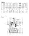
- FIG. 2 shows a preferred embodiment of valve 14.
- the valve 14 comprises a housing 38, a base 40, a valve disk 42 and a shaft 44.
- the housing 38 has two openings at its lower and upper sides, respectively.
- the base 40 is fixed with its top face to the lower side of the housing 38 and covers the lower opening.
- the valve disk 42 is located inside the housing 38 on the top face of the base 40 and is pressed with its top face to the lower end of the shaft 44 by a spring 45.
- the shaft 44 is supported by a bearing 46 inside the housing 38 and extends upwards through the upper opening.
- the upper end of the shaft is connected to the valve drive 36.
- the drive 36 may turn the valve disk 42 via the shaft 44.
- the valve base 40 has four side faces each having a bore, said four bores being the aerosol inlet 28, the aerosol outlet 30, the first connector 32 and the second connector 34, respectively.
- Each bore 28, 30, 32, 34 is continued at its inner end by a corresponding channel 48 inclined upwardly towards the top face of the base 40 and ending in a corresponding top opening 50, 52, 54, 56.
- each bore 28, 30, 32, 34 is connected via one of the four inclined channels 48 with an assigned top opening 50, 52, 54, 56.
- the valve disk 42 has two kidney shaped bent channels 66 and 68, so that the bent channel 66 connects the top openings 52 and 54 and the bent channel 68 connects the top openings 50 and 56.
- the four/two direction control valve 14 may adopt two positions as shown in Figure 6 and 7.
- the valve disk 42 In the first position of the valve 14, the valve disk 42 is in the position shown in Figure 4 so that the top openings 50, 52, 54, 56 are aligned in pairs 50 with 56 and 52 with 54 and connected with the ends of the channels 68 and 66 respectively.
- the valve disk 42 In the second position of the valve 14, the valve disk 42 is in a position turned clockwise by 90 degrees from the position shown in Figure 4 so that now the top openings 50, 52, 54, 56 are aligned in pairs 50 with 54 and 52 with 56 and connected with the ends of the channels 68 and 66 respectively.
- valve when the valve is in the first position, for example by the position of the valve disk 42 shown in Figure 4, it connects the first connector 32 to the outlet 30 via the top opening 54, the bent channel 66, and top opening 52. Additionally the valve is connecting the second connector 34 to the inlet 28 via the top opening 56, the bent channel 68, and top opening 50.
- valve 14 When the valve 14 is in the second position, for example by the position of the valve disk 42 turned clockwise by 90 degrees from the position shown in Figure 4, it connects the second connector 34 to the outlet 30 via the top opening 56, the bent channel 66, and the top opening 52. Additionally the valve is connecting the first connector 32 to the inlet 28 via the top opening 54, the bent channel 68, and the top opening 50.
- valve disk 42 is turned either clockwise or counterclockwise by 90 degrees.
- a pneumatic drive alternates the turning direction of the valve disk 42 with every cycle while an electrical drive stepwise turns the valve disk 42 in the same direction by 90 degrees steps.
- Figure 5 contains three graphs showing from top to bottom the time dependant status of the external or internal synchronization signal 135, the time dependent suction volume flow profile and the time dependent exhaust volume flow profile in a first operation mode of the aerosol pump system generating the sinusoidal suction volume flow profile.
- the pump system is part of a smoking machine (not shown) and the aerosol inlet 28 is connected to a cigarette 70 to be smoked and the aerosol outlet 30 is connected to a smoke analyzing instrument (not shown).
- the drive 36 is actuated by the control unit by the synchronization signal 135 so as to switch the valve 14 into the first position (see Figure 6) in which the first pump 10 is connected to the outlet 30 and the smoke analyzing instrument and the second pump 12 is connected to the aerosol inlet 28 and the cigarette 70.
- the first motor 20 is activated by the control unit to push the piston 18 in the cylinder 16 so that the first pump 10 performs an exhaust stroke 115
- the second motor 26 is activated by the control unit to pull the piston 24 in the cylinder 22 so that the second pump 12 performs simultaneously a suction stroke 120. In doing so, smoke is drawn from the cigarette 70 into the cylinder 22 of the second pump 12 and air, gas or aerosol still contained in cylinder 16 is exhausted from the cylinder 16 of the first pump 10 out to the smoke analyzing instrument.
- the next operation cycle 130 starts and the drive 36 is actuated by the control unit so as to switch the valve 14 into the second position (see Figure 7) in which the second pump 12 is connected to the outlet 30 and the smoke analyzing instrument and the first pump 10 is connected to the aerosol inlet 28 and the cigarette 70.
- the first motor 20 is activated by the control unit to pull the piston 18 in the cylinder 16 so that the first pump 10 performs a suction stroke 110
- the second motor 26 is activated by the control unit to push the piston 24 in the cylinder 22 so that the second pump 12 simultaneously performs an exhaust stroke 125. In doing so, new smoke is drawn from the cigarette 70 into the cylinder 16 of the first pump 10 and the previously generated smoke is exhausted from the cylinder 22 of the second pump 12 out to the smoke analyzing instrument.
- the next operation cycle starts and the valve 14 is switched again into the first position (see Figure 6), and then the first pump 10 performs again the exhaust stroke 115 to blow the previously generated smoke out to the smoke analyzing instrument, while the second pump 12 simultaneously performs again the suction stroke 120 to draw new smoke from the cigarette 70.
- the exhaust aerosol flow is substantially continuous with the exception of the short valve switching time.
- the control unit controls the suction strokes of the pumps 10, 12 in such a manner that the suction volume flow profile is a sinusoidal profile according to the ISO requirements ( Figure 5). Further, the control unit controls the exhaust strokes of the pumps 10, 12 in such a manner that the exhaust volume flow profile is substantially rectangular profile ( Figure 5).
- Figure 8 is similar to Figure 5 but relates to a different configuration mode of the control unit for the pump system which differs from the first operation mode in the suction volume flow profile being an individually defined profile recorded, for example during tobacco smoking, resulting in a more complex shape of suction strokes 140, 150.
Landscapes
- Engineering & Computer Science (AREA)
- Mechanical Engineering (AREA)
- General Engineering & Computer Science (AREA)
- Details Of Reciprocating Pumps (AREA)
- Compressor (AREA)
- Compressors, Vaccum Pumps And Other Relevant Systems (AREA)
Abstract
- a first piston pump (10);
- a first motor (20) for driving the first piston pump (10);
- a second piston pump (12);
- a second motor (26) for driving the second piston pump (12);
- a directional control valve (14);
- wherein, in a first position of the valve (14), the valve (14) is connecting the first connector (32) to the outlet (30) and the second connector (34) to the inlet (28) and,
- wherein, in a second position of the valve (14), the valve (14) is connecting the second connector (34) to the outlet (30) and the first connector (32) to the inlet (28); and
- a valve drive (36) for driving the valve (14) from said first position to said second position and vice versa and a smoking machine comprising such a pump system.
Description
- The present invention relates to a new pump system suitable for gases, liquids and particularly aerosols.
- Known aerosol pump systems are used for example in so called smoking machines allowing reproducible cigarette smoking under standard conditions according to DIN ISO 3308 or DIN ISO 4387. An aerosol is for example the condensed and cooled mixture of gases passing down a cigarette and issuing through the butt end of a cigarette.
- In operation a cigarette smoking machine automatically smokes a cigarette in a series of puffs. During each puff a piston pump first performs a suction stroke according to a suction volume flow profile. The suction stroke draws smoke from the cigarette into the cylinder of the pump. Then the piston pump performs an exhaust stroke according to an exhaust volume flow profile to exhaust the smoke out of the cylinder of the pump. The smoke is then for example transported into an analyzing device to analyze the smoke constituents.
- Such a smoking machine with a one piston pump system is disclosed in the
German patent DE3537580 . This smoking machine further comprises a programmable drive for the piston pump system which allows the application of different suction or exhaust volume flow profiles during puffs. - In existing aerosol pump systems, particularly for smoking machines the aerosol is conveyed in a discontinuous stream due to the alternating suction and exhaust strokes of the piston pump. To improve the quality of measurements of smoke constituents it would be desirable if the aerosol could be provided in a continuous stream or volume flow.
- It is the object of the present invention to provide a pump system, particularly a pump system suitable for aerosols, which is capable of providing a substantially continuous stream or volume flow.
- According to the present invention there is provided a pump system, comprising:
- a first piston pump,
- a first motor for driving the first piston pump,
- a second piston pump,
- a second motor for driving the second piston pump,
- a directional control valve comprising an inlet, an outlet, a first connector connected to the first pump, and a second connector connected to the second pump,
- wherein, in a first position of the valve, the valve connects the first connector to the outlet, and the second connector to the inlet, and
- wherein, in a second position of the valve, the valve connects the second connector to the outlet and the first connector to the inlet, and
- a valve drive for driving the valve from said first position to said second position and vice versa.
- The pump system according to the present invention is suitable for pumping any aerosol, gas, liquid, or suspension.
- By alternating the suction strokes of the two pumps as well as the exhaust strokes of the pumps a substantially continuous stream or volume flow can be produced. The volume flow is only interrupted by the switching time of the valve, that is, the time needed to switch between the first position and the second position of the valve. The switching time may advantageously be reduced by appropriately designing the geometry of the valve, for example as described below.
- A substantially continuous volume flow with minimal interruption is particularly advantageous if the pump system is connected at its outlet to the inlet of an aerosol analyzing instrument, for example as part of a smoking machine. Such an aerosol analyzing instrument comprises an aerosol chamber and one or more sensors inside this chamber so that the measuring conditions to measure for example smoke constituents are substantially constant. Examples for such aerosol analyzing instrument are trapping or exposing systems for cigarette smoke which are required for smoke chemistry or toxicology investigations.
- In a preferred embodiment, the pump system of the invention further comprises a control unit connected to the first piston pump, the second piston pump and the valve drive, the control unit controlling the two piston pump motors and the valve drive such that when the valve is in the first position, the first pump performs an exhaust stroke while the second pump simultaneously performs a suction stroke, and, when the valve is in the second position, the second pump performs an exhaust stroke while the first pump simultaneously performs a suction stroke.
- In a further preferred embodiment, the control unit of the pump system is capable of generating various volume flow profiles at the inlet as well as at the outlet. Preferably, the control unit independently drives the two piston pumps such that the resulting volume flow profiles of the piston pumps may be the same or different. More preferably, the settings for the volume flow profiles are configured individually for every piston stroke cycle. The volume flow profiles may be sinusoidal, such as the ISO standard profile, rectangular, trapezoidal, or any individually defined volume flow profiles for example recorded during tobacco smoking.
- In a further preferred embodiment, the control unit of the pump system is configured to vary the operation parameters of the pump system, such as the shape of the volume flow profiles, pump stroke volume, pump stroke duration, pump stroke period, exhaust pump stroke duration, and number of pump strokes per analysis object. In combination with a smoking machine, a stroke represent the individual puffs generated from for example a cigarette, a cigar or a pipe.
- In a further preferred embodiment, the control unit of the pump system is configured to synchronize the operation of the pump system with external processes. The control unit may be either in the master position, synchronizing external processes or instruments, or operating as a slave, triggered by an external instrument like for example a smoking machine.
- Preferably, the control unit is configured to adapt differently sized cylinders and pistons for the piston pumps. The configuration of the control unit may be performed via an operator console, an on-board web server, or both.
- Preferably, the pump system allows generating reproducible flow profiles at the aerosol generation source, for example the cigarette, independent of additional flow resistances or void volumes of for example trapping or exposing systems.
- In a further preferred embodiment the volume flow profile or profiles of the exhaust stroke of the first pump or the second pump or both pumps is different from the flow profile of the suction stroke of the first pump or the second pump. Preferably the flow profile of the exhaust stroke of the first pump may be the same as the flow profile of the exhaust stroke of the second pump or that the flow profile of the suction stroke of the first pump is the same as the flow profile of the suction stroke of the second pump or both. For example, the exhaust strokes of both pumps may have the same rectangular profile whereas the suction strokes of both pumps may have the same sinus profile according to the ISO requirements for cigarette smoking machines. Alternatively, the suction volume flow profile may mimic any individually defined volume flow profile, for example a profile recorded during tobacco smoking.
- In a further preferred embodiment, the valve comprises channels for the connections of the first connector to the outlet and the second connector to the inlet, when in the first position and channels for the connection of the second position. Furthermore a first line connects the first connector to the first pump, and a second line connects the second connector to the second pump, wherein the channels, the first line, the second line, the inlet and the outlet have a constant cross-sectional area over their whole length.
- The constant cross-sectional area reduces deposition losses of an aerosol on the surfaces of the aerosol conveying ducts in the pump system which would otherwise contaminate the pump system. This advantageously reduces the downtime of the pump system for cleaning. Preferably, the parts of the pump system which may come in contact with the aerosol, are made of suitable inert materials, such as glass, stainless steel, fluorine caoutchouc (FKM) or polyetheretherketone (PEEK) or other, to reduce the chemical interaction of the aerosol with the surfaces of the pump system.
- In a further, preferred embodiment the channels, the first line and the second line have no edges. Thus the suction line of the aerosol from the inlet through the valve to the piston pump and the exhaust line from the piston pump through the valve to the outlet have only smooth surfaces and curves which also contribute to reducing the deposition losses of the aerosol on the surfaces of the pump system.
- In the following, a particularly preferred and advantageous embodiment of the pump system according to the present invention is described in detail with reference to the schematic drawings.
- Figure 1 shows a side view and a plan view of the pump system;
- Figure 2 shows a longitudinal cross-sectional view of a preferred valve of the pump system;
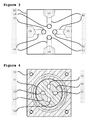
- Figure 3 shows a top view onto the base of said valve;
- Figure 4 shows a cross-sectional view along line VI-VI of Figure 2;
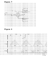
- Figure 5 shows a time-volume flow graph of the suction flow with a sinusoidal flow profile and the exhaust flow with a rectangular profile in a first operation mode of the pump system;
- Figure 6 shows the set-up of the valve and the piston pumps during the first cycle of operation;
- Figure 7 shows the set-up of the valve and the piston pump during the second cycle of operation; and
- Figure 8 shows a time-volume flow graph of the suction flow with an individually defined flow profile and the exhaust flow with a rectangular flow profile in a second operation mode of the pump system.
- Figure 1 shows schematically a pump system according to the present invention. The pump system comprises a
first piston pump 10, asecond piston pump 12 and adirectional control valve 14. - The
first pump 10 comprises a cylinder 16, apiston 18 inside the cylinder 16, and a first motor 20 for driving thepiston 18. Thesecond pump 12 comprises a cylinder 22, a piston 24 inside the cylinder 22, and a second motor 26 for driving the piston 24. - The
valve 14 is a four/two directional control valve comprising anaerosol inlet 28, anaerosol outlet 30, afirst connector 32 connected to thefirst pump 10 via a first line 33, and asecond connector 34 connected to thesecond pump 12 via asecond line 35, see also figure 3. The aerosol pump system further comprises avalve drive 36, for example a pneumatic drive connected to thevalve 14 for driving it from a first position to a second position and vice versa. - The pump system also comprises a
programmable control unit 100 connected to thefirst pump 10, thesecond pump 12 and thedrive 36. - Figure 2 shows a preferred embodiment of
valve 14. Thevalve 14 comprises ahousing 38, abase 40, avalve disk 42 and ashaft 44. Thehousing 38 has two openings at its lower and upper sides, respectively. Thebase 40 is fixed with its top face to the lower side of thehousing 38 and covers the lower opening. Thevalve disk 42 is located inside thehousing 38 on the top face of thebase 40 and is pressed with its top face to the lower end of theshaft 44 by aspring 45. Theshaft 44 is supported by abearing 46 inside thehousing 38 and extends upwards through the upper opening. The upper end of the shaft is connected to thevalve drive 36. Thus, thedrive 36 may turn thevalve disk 42 via theshaft 44. - As shown in Figure 3, the
valve base 40 has four side faces each having a bore, said four bores being theaerosol inlet 28, theaerosol outlet 30, thefirst connector 32 and thesecond connector 34, respectively. Each bore 28, 30, 32, 34 is continued at its inner end by a correspondingchannel 48 inclined upwardly towards the top face of thebase 40 and ending in a correspondingtop opening inclined channels 48 with an assignedtop opening - As shown in Figure 4, the
valve disk 42 has two kidney shapedbent channels bent channel 66 connects thetop openings bent channel 68 connects thetop openings - The four/two
direction control valve 14 may adopt two positions as shown in Figure 6 and 7. In the first position of thevalve 14, thevalve disk 42 is in the position shown in Figure 4 so that thetop openings pairs 50 with 56 and 52 with 54 and connected with the ends of thechannels valve 14, thevalve disk 42 is in a position turned clockwise by 90 degrees from the position shown in Figure 4 so that now thetop openings pairs 50 with 54 and 52 with 56 and connected with the ends of thechannels - Thus, when the valve is in the first position, for example by the position of the
valve disk 42 shown in Figure 4, it connects thefirst connector 32 to theoutlet 30 via thetop opening 54, thebent channel 66, andtop opening 52. Additionally the valve is connecting thesecond connector 34 to theinlet 28 via thetop opening 56, thebent channel 68, andtop opening 50. When thevalve 14 is in the second position, for example by the position of thevalve disk 42 turned clockwise by 90 degrees from the position shown in Figure 4, it connects thesecond connector 34 to theoutlet 30 via thetop opening 56, thebent channel 66, and thetop opening 52. Additionally the valve is connecting thefirst connector 32 to theinlet 28 via thetop opening 54, thebent channel 68, and thetop opening 50. Thus, in the first position, thefirst pump 10 is connected to theoutlet 30 and thesecond pump 12 is connected to theaerosol inlet 28, whereas in the second position, thesecond pump 12 is connected to theoutlet 30 and thefirst pump 10 is connected to theaerosol inlet 28. - To switch the
valve 14 between the first and second position thevalve disk 42 is turned either clockwise or counterclockwise by 90 degrees. A pneumatic drive alternates the turning direction of thevalve disk 42 with every cycle while an electrical drive stepwise turns thevalve disk 42 in the same direction by 90 degrees steps. - In the following, the operation of the aerosol pump system will be described.
- Figure 5 contains three graphs showing from top to bottom the time dependant status of the external or
internal synchronization signal 135, the time dependent suction volume flow profile and the time dependent exhaust volume flow profile in a first operation mode of the aerosol pump system generating the sinusoidal suction volume flow profile. In this exemplary application the pump system is part of a smoking machine (not shown) and theaerosol inlet 28 is connected to acigarette 70 to be smoked and theaerosol outlet 30 is connected to a smoke analyzing instrument (not shown). - At the beginning of an
operation cycle 130 thedrive 36 is actuated by the control unit by thesynchronization signal 135 so as to switch thevalve 14 into the first position (see Figure 6) in which thefirst pump 10 is connected to theoutlet 30 and the smoke analyzing instrument and thesecond pump 12 is connected to theaerosol inlet 28 and thecigarette 70. During or at the end of the switching, the first motor 20 is activated by the control unit to push thepiston 18 in the cylinder 16 so that thefirst pump 10 performs anexhaust stroke 115, and the second motor 26 is activated by the control unit to pull the piston 24 in the cylinder 22 so that thesecond pump 12 performs simultaneously asuction stroke 120. In doing so, smoke is drawn from thecigarette 70 into the cylinder 22 of thesecond pump 12 and air, gas or aerosol still contained in cylinder 16 is exhausted from the cylinder 16 of thefirst pump 10 out to the smoke analyzing instrument. - At the end of the
suction stroke 120, thenext operation cycle 130 starts and thedrive 36 is actuated by the control unit so as to switch thevalve 14 into the second position (see Figure 7) in which thesecond pump 12 is connected to theoutlet 30 and the smoke analyzing instrument and thefirst pump 10 is connected to theaerosol inlet 28 and thecigarette 70. During or at the end of the switching, the first motor 20 is activated by the control unit to pull thepiston 18 in the cylinder 16 so that thefirst pump 10 performs asuction stroke 110, and the second motor 26 is activated by the control unit to push the piston 24 in the cylinder 22 so that thesecond pump 12 simultaneously performs anexhaust stroke 125. In doing so, new smoke is drawn from thecigarette 70 into the cylinder 16 of thefirst pump 10 and the previously generated smoke is exhausted from the cylinder 22 of thesecond pump 12 out to the smoke analyzing instrument. - At the end of the
suction stroke 110, the next operation cycle starts and thevalve 14 is switched again into the first position (see Figure 6), and then thefirst pump 10 performs again theexhaust stroke 115 to blow the previously generated smoke out to the smoke analyzing instrument, while thesecond pump 12 simultaneously performs again thesuction stroke 120 to draw new smoke from thecigarette 70. As can be seen from the graph in Figure 5 the exhaust aerosol flow is substantially continuous with the exception of the short valve switching time. - According to the first operation mode of the pump system, the control unit controls the suction strokes of the
pumps pumps - Figure 8 is similar to Figure 5 but relates to a different configuration mode of the control unit for the pump system which differs from the first operation mode in the suction volume flow profile being an individually defined profile recorded, for example during tobacco smoking, resulting in a more complex shape of suction strokes 140, 150.
-
- 10
- first piston pump
- 12
- second piston pump
- 14
- directional control valve
- 16
- cylinder of 10
- 18
- piston of 10
- 20
- first motor
- 22
- cylinder of 12
- 24
- piston of 12
- 26
- second motor
- 28
- aerosol inlet
- 30
- aerosol outlet
- 32
- first connector
- 33
- first line
- 34
- second connector
- 35
- second line
- 36
- valve drive
- 38
- housing
- 40
- base
- 42
- valve disk
- 44
- shaft
- 45
- spring
- 46
- bearings
- 48
- inclined channels in 40
- 50
- top opening in 40 from aerosol inlet
- 52
- top opening in 40 from aerosol outlet
- 54
- top opening in 40 from first connector
- 56
- top opening in 40 from second connector
- 66, 68
- bent channels in 42
- 70
- cigarette
- 100
- control unit
- 110, 120, 140, 150
- suction stroke
- 115, 125
- exhaust stroke
- 130
- operation cycle
- 135
- synchronization signal
Claims (9)
- Pump system, comprising:- a first piston pump (10);- a first motor (20) for driving the first piston pump (10);- a second piston pump (12);- a second motor (26) for driving the second piston pump (12);- a directional control valve (14);- wherein, in a first position of the valve (14), the valve (14) connects the first connector (32) to the outlet (30) and the second connector (34) to the inlet (28) and,- wherein, in a second position of the valve (14), the valve (14) connects the second connector (34) to the outlet (30) and the first connector (32) to the inlet (28); and- a valve drive (36) for driving the valve (14) from said first position to said second position and vice versa.
- Pump system according to claim 1,
further comprising a control unit (100) connected to the first piston pump (10), the second piston pump (12) and the valve drive (36); the control unit (100) controlling the two piston pump motors (20, 26) and the valve drive (36) such that, when the valve (14) is in the first position, the first pump (10) performs an exhaust stroke and the second pump (12) performs a suction stroke, and, when the valve (14) is in the second position, the second pump (12) performs an exhaust stroke and the first pump (10) performs a suction stroke. - Pump system according to one of the preceding claims,
wherein the flow profile of the exhaust stroke of the first (10) pump, or the second pump (12) or the flow profile of the fist pump (10) and the second pump (12) is different from the flow profile of the suction stroke of the first (10) pump, or the second pump (12) or the flow profile of the suction stroke of the first pump (10) and the second pump (12). - Pump system according to claim 3,
wherein the control unit (100) of the pump system is configured to vary at least one of the operation parameters: shape of the volume flow profiles, pump stroke volume, suction pump stroke duration, pump stroke period, exhaust pump stroke duration, number of pump strokes per analysis object. - Pump system according to claim 3 or 4,
wherein the definition of the flow profiles is individually settable by the programmable control unit on a cycle to cycle base. - Pump system according to one of the preceding claims,
wherein:- the valve (14) comprises channels (48, 66, 68) for the connections of the first connector (32) to the outlet (30) and the second connector (34) to the inlet (28), when in the first position and for the connections of the second connector (34) to the outlet (30) and the first connector (32) to the inlet (28), when in the second position;- a first line connects the first connector (32) to the first pump (10), and a second line connects the second connector (34) to the second pump (12);- the channels (48, 66, 68), the first line and the second line have the same cross-sectional area. - Pump system according to claim 6,
wherein the channels (48, 66, 68), the first line and the second line have no edges. - Pump system according to one of the preceding claims,
wherein parts of the valve (14) are made of inert materials, such as glass, stainless steel, fluorine caoutchouc or polyetheretherketone. - Smoking machine for the reproducible cigarette smoking under standard conditions, comprising a pump system according to one of the preceding claims.
Priority Applications (5)
| Application Number | Priority Date | Filing Date | Title |
|---|---|---|---|
| PL06110921T PL1832745T3 (en) | 2006-03-09 | 2006-03-09 | Pump system |
| ES06110921.1T ES2653154T3 (en) | 2006-03-09 | 2006-03-09 | Pump system |
| HUE06110921A HUE037652T2 (en) | 2006-03-09 | 2006-03-09 | Pump system |
| PT61109211T PT1832745T (en) | 2006-03-09 | 2006-03-09 | Pump system |
| EP06110921.1A EP1832745B1 (en) | 2006-03-09 | 2006-03-09 | Pump system |
Applications Claiming Priority (1)
| Application Number | Priority Date | Filing Date | Title |
|---|---|---|---|
| EP06110921.1A EP1832745B1 (en) | 2006-03-09 | 2006-03-09 | Pump system |
Publications (2)
| Publication Number | Publication Date |
|---|---|
| EP1832745A1 true EP1832745A1 (en) | 2007-09-12 |
| EP1832745B1 EP1832745B1 (en) | 2017-12-13 |
Family
ID=36778269
Family Applications (1)
| Application Number | Title | Priority Date | Filing Date |
|---|---|---|---|
| EP06110921.1A Expired - Lifetime EP1832745B1 (en) | 2006-03-09 | 2006-03-09 | Pump system |
Country Status (5)
| Country | Link |
|---|---|
| EP (1) | EP1832745B1 (en) |
| ES (1) | ES2653154T3 (en) |
| HU (1) | HUE037652T2 (en) |
| PL (1) | PL1832745T3 (en) |
| PT (1) | PT1832745T (en) |
Cited By (2)
| Publication number | Priority date | Publication date | Assignee | Title |
|---|---|---|---|---|
| WO2014118286A2 (en) | 2013-01-30 | 2014-08-07 | Philip Morris Products S.A | Improved aerosol from tobacco |
| US12053029B1 (en) | 2020-04-21 | 2024-08-06 | Data Science International, Inc. | Systems and methods for testing one or more smoking articles |
Citations (3)
| Publication number | Priority date | Publication date | Assignee | Title |
|---|---|---|---|---|
| GB136025A (en) * | 1919-02-05 | 1919-12-11 | Alexander Buchanan Allan | Improvements in Vacuum Pumps. |
| US4836223A (en) * | 1985-10-19 | 1989-06-06 | Heinrich Burghart Elektro- Und Feinmechanik Gmbh | Cigarette smoking device |
| WO2005106246A1 (en) * | 2004-04-28 | 2005-11-10 | Siemens Aktiengesellschaft | Valve system |
Family Cites Families (1)
| Publication number | Priority date | Publication date | Assignee | Title |
|---|---|---|---|---|
| US3022738A (en) * | 1959-04-20 | 1962-02-27 | Krute Everett Archie | Pump systems |
-
2006
- 2006-03-09 ES ES06110921.1T patent/ES2653154T3/en not_active Expired - Lifetime
- 2006-03-09 HU HUE06110921A patent/HUE037652T2/en unknown
- 2006-03-09 PT PT61109211T patent/PT1832745T/en unknown
- 2006-03-09 PL PL06110921T patent/PL1832745T3/en unknown
- 2006-03-09 EP EP06110921.1A patent/EP1832745B1/en not_active Expired - Lifetime
Patent Citations (3)
| Publication number | Priority date | Publication date | Assignee | Title |
|---|---|---|---|---|
| GB136025A (en) * | 1919-02-05 | 1919-12-11 | Alexander Buchanan Allan | Improvements in Vacuum Pumps. |
| US4836223A (en) * | 1985-10-19 | 1989-06-06 | Heinrich Burghart Elektro- Und Feinmechanik Gmbh | Cigarette smoking device |
| WO2005106246A1 (en) * | 2004-04-28 | 2005-11-10 | Siemens Aktiengesellschaft | Valve system |
Cited By (3)
| Publication number | Priority date | Publication date | Assignee | Title |
|---|---|---|---|---|
| WO2014118286A2 (en) | 2013-01-30 | 2014-08-07 | Philip Morris Products S.A | Improved aerosol from tobacco |
| US10779570B2 (en) | 2013-01-30 | 2020-09-22 | Philip Morris Products S.A. | Aerosol from tobacco |
| US12053029B1 (en) | 2020-04-21 | 2024-08-06 | Data Science International, Inc. | Systems and methods for testing one or more smoking articles |
Also Published As
| Publication number | Publication date |
|---|---|
| HUE037652T2 (en) | 2018-09-28 |
| ES2653154T3 (en) | 2018-02-06 |
| PT1832745T (en) | 2018-01-29 |
| EP1832745B1 (en) | 2017-12-13 |
| PL1832745T3 (en) | 2018-04-30 |
Similar Documents
| Publication | Publication Date | Title |
|---|---|---|
| CN101668948A (en) | Pneumatic pump | |
| JP2004210544A (en) | Pump device for powder, method for powder and powder coating device | |
| KR101771416B1 (en) | Ambient air monitoring system and method using sensor and gas chromatography | |
| US6257835B1 (en) | Dry vacuum pump system for gas sorption analyzer | |
| GB2441943A (en) | Ultra compact ion mobility based analyzer system and method | |
| EP1832745B1 (en) | Pump system | |
| JP2021521429A5 (en) | ||
| CN1737372A (en) | Liquid feeding system | |
| JPH09257666A (en) | Injection device and method for simultaneous aspiration and dispensing of fluid | |
| JPH0445781B2 (en) | ||
| CN101801823A (en) | Improved device for transporting powders along pipes | |
| CN117191500A (en) | Analytical device with motor and cam disc and analytical method using such analytical device | |
| RU2308210C2 (en) | Apparatus and method for controlling of filter-tipped cigarette | |
| EP1421903A1 (en) | Arrangement for passive gas sampling | |
| EP2425214B1 (en) | Method for testing metered-dose-ejection devices and apparatus therefor | |
| KR102163409B1 (en) | Suction roll system | |
| JP2009519826A5 (en) | ||
| NO20063897L (en) | Liquid test sensor with air ducts for directing fluid flow | |
| JP2006292392A (en) | Liquid feeding system | |
| JP4377900B2 (en) | Liquid chromatograph | |
| KR102157126B1 (en) | Dual sample loop type ambient air monitoring system and method using sensor and gas chromatography | |
| US20140000343A1 (en) | Handheld sampling-removal head, analysis arrangement and method for characterizing an aerosol | |
| CN117074111A (en) | A single cigarette real-person simulated smoking detection device | |
| CN216727174U (en) | Bionic aerosol generating device | |
| WO2008010034A3 (en) | Apparatus and method for forming ceramic products |
Legal Events
| Date | Code | Title | Description |
|---|---|---|---|
| PUAI | Public reference made under article 153(3) epc to a published international application that has entered the european phase |
Free format text: ORIGINAL CODE: 0009012 |
|
| AK | Designated contracting states |
Kind code of ref document: A1 Designated state(s): AT BE BG CH CY CZ DE DK EE ES FI FR GB GR HU IE IS IT LI LT LU LV MC NL PL PT RO SE SI SK TR |
|
| AX | Request for extension of the european patent |
Extension state: AL BA HR MK YU |
|
| 17P | Request for examination filed |
Effective date: 20080206 |
|
| 17Q | First examination report despatched |
Effective date: 20080409 |
|
| AKX | Designation fees paid |
Designated state(s): AT BE BG CH CY CZ DE DK EE ES FI FR GB GR HU IE IS IT LI LT LU LV MC NL PL PT RO SE SI SK TR |
|
| GRAP | Despatch of communication of intention to grant a patent |
Free format text: ORIGINAL CODE: EPIDOSNIGR1 |
|
| INTG | Intention to grant announced |
Effective date: 20170704 |
|
| GRAS | Grant fee paid |
Free format text: ORIGINAL CODE: EPIDOSNIGR3 |
|
| GRAA | (expected) grant |
Free format text: ORIGINAL CODE: 0009210 |
|
| AK | Designated contracting states |
Kind code of ref document: B1 Designated state(s): AT BE BG CH CY CZ DE DK EE ES FI FR GB GR HU IE IS IT LI LT LU LV MC NL PL PT RO SE SI SK TR |
|
| REG | Reference to a national code |
Ref country code: GB Ref legal event code: FG4D |
|
| REG | Reference to a national code |
Ref country code: AT Ref legal event code: REF Ref document number: 954656 Country of ref document: AT Kind code of ref document: T Effective date: 20171215 Ref country code: CH Ref legal event code: EP Ref country code: CH Ref legal event code: NV Representative=s name: VENI GMBH, CH |
|
| REG | Reference to a national code |
Ref country code: RO Ref legal event code: EPE |
|
| REG | Reference to a national code |
Ref country code: SE Ref legal event code: TRGR |
|
| REG | Reference to a national code |
Ref country code: IE Ref legal event code: FG4D |
|
| REG | Reference to a national code |
Ref country code: DE Ref legal event code: R096 Ref document number: 602006054312 Country of ref document: DE |
|
| REG | Reference to a national code |
Ref country code: NL Ref legal event code: FP |
|
| REG | Reference to a national code |
Ref country code: PT Ref legal event code: SC4A Ref document number: 1832745 Country of ref document: PT Date of ref document: 20180129 Kind code of ref document: T Free format text: AVAILABILITY OF NATIONAL TRANSLATION Effective date: 20180119 |
|
| REG | Reference to a national code |
Ref country code: ES Ref legal event code: FG2A Ref document number: 2653154 Country of ref document: ES Kind code of ref document: T3 Effective date: 20180206 |
|
| REG | Reference to a national code |
Ref country code: FR Ref legal event code: PLFP Year of fee payment: 13 |
|
| REG | Reference to a national code |
Ref country code: LT Ref legal event code: MG4D |
|
| PG25 | Lapsed in a contracting state [announced via postgrant information from national office to epo] |
Ref country code: LT Free format text: LAPSE BECAUSE OF FAILURE TO SUBMIT A TRANSLATION OF THE DESCRIPTION OR TO PAY THE FEE WITHIN THE PRESCRIBED TIME-LIMIT Effective date: 20171213 Ref country code: FI Free format text: LAPSE BECAUSE OF FAILURE TO SUBMIT A TRANSLATION OF THE DESCRIPTION OR TO PAY THE FEE WITHIN THE PRESCRIBED TIME-LIMIT Effective date: 20171213 |
|
| REG | Reference to a national code |
Ref country code: AT Ref legal event code: MK05 Ref document number: 954656 Country of ref document: AT Kind code of ref document: T Effective date: 20171213 |
|
| PG25 | Lapsed in a contracting state [announced via postgrant information from national office to epo] |
Ref country code: GR Free format text: LAPSE BECAUSE OF FAILURE TO SUBMIT A TRANSLATION OF THE DESCRIPTION OR TO PAY THE FEE WITHIN THE PRESCRIBED TIME-LIMIT Effective date: 20180314 Ref country code: LV Free format text: LAPSE BECAUSE OF FAILURE TO SUBMIT A TRANSLATION OF THE DESCRIPTION OR TO PAY THE FEE WITHIN THE PRESCRIBED TIME-LIMIT Effective date: 20171213 Ref country code: BG Free format text: LAPSE BECAUSE OF FAILURE TO SUBMIT A TRANSLATION OF THE DESCRIPTION OR TO PAY THE FEE WITHIN THE PRESCRIBED TIME-LIMIT Effective date: 20180313 |
|
| PG25 | Lapsed in a contracting state [announced via postgrant information from national office to epo] |
Ref country code: SK Free format text: LAPSE BECAUSE OF FAILURE TO SUBMIT A TRANSLATION OF THE DESCRIPTION OR TO PAY THE FEE WITHIN THE PRESCRIBED TIME-LIMIT Effective date: 20171213 Ref country code: EE Free format text: LAPSE BECAUSE OF FAILURE TO SUBMIT A TRANSLATION OF THE DESCRIPTION OR TO PAY THE FEE WITHIN THE PRESCRIBED TIME-LIMIT Effective date: 20171213 Ref country code: CY Free format text: LAPSE BECAUSE OF FAILURE TO SUBMIT A TRANSLATION OF THE DESCRIPTION OR TO PAY THE FEE WITHIN THE PRESCRIBED TIME-LIMIT Effective date: 20171213 |
|
| PG25 | Lapsed in a contracting state [announced via postgrant information from national office to epo] |
Ref country code: AT Free format text: LAPSE BECAUSE OF FAILURE TO SUBMIT A TRANSLATION OF THE DESCRIPTION OR TO PAY THE FEE WITHIN THE PRESCRIBED TIME-LIMIT Effective date: 20171213 Ref country code: IS Free format text: LAPSE BECAUSE OF FAILURE TO SUBMIT A TRANSLATION OF THE DESCRIPTION OR TO PAY THE FEE WITHIN THE PRESCRIBED TIME-LIMIT Effective date: 20180413 |
|
| REG | Reference to a national code |
Ref country code: DE Ref legal event code: R097 Ref document number: 602006054312 Country of ref document: DE |
|
| REG | Reference to a national code |
Ref country code: HU Ref legal event code: AG4A Ref document number: E037652 Country of ref document: HU |
|
| PLBE | No opposition filed within time limit |
Free format text: ORIGINAL CODE: 0009261 |
|
| STAA | Information on the status of an ep patent application or granted ep patent |
Free format text: STATUS: NO OPPOSITION FILED WITHIN TIME LIMIT |
|
| 26N | No opposition filed |
Effective date: 20180914 |
|
| PG25 | Lapsed in a contracting state [announced via postgrant information from national office to epo] |
Ref country code: MC Free format text: LAPSE BECAUSE OF FAILURE TO SUBMIT A TRANSLATION OF THE DESCRIPTION OR TO PAY THE FEE WITHIN THE PRESCRIBED TIME-LIMIT Effective date: 20171213 Ref country code: DK Free format text: LAPSE BECAUSE OF FAILURE TO SUBMIT A TRANSLATION OF THE DESCRIPTION OR TO PAY THE FEE WITHIN THE PRESCRIBED TIME-LIMIT Effective date: 20171213 |
|
| REG | Reference to a national code |
Ref country code: BE Ref legal event code: MM Effective date: 20180331 |
|
| REG | Reference to a national code |
Ref country code: IE Ref legal event code: MM4A |
|
| PG25 | Lapsed in a contracting state [announced via postgrant information from national office to epo] |
Ref country code: LU Free format text: LAPSE BECAUSE OF NON-PAYMENT OF DUE FEES Effective date: 20180309 |
|
| PG25 | Lapsed in a contracting state [announced via postgrant information from national office to epo] |
Ref country code: IE Free format text: LAPSE BECAUSE OF NON-PAYMENT OF DUE FEES Effective date: 20180309 |
|
| PG25 | Lapsed in a contracting state [announced via postgrant information from national office to epo] |
Ref country code: SI Free format text: LAPSE BECAUSE OF FAILURE TO SUBMIT A TRANSLATION OF THE DESCRIPTION OR TO PAY THE FEE WITHIN THE PRESCRIBED TIME-LIMIT Effective date: 20171213 Ref country code: BE Free format text: LAPSE BECAUSE OF NON-PAYMENT OF DUE FEES Effective date: 20180331 |
|
| PGFP | Annual fee paid to national office [announced via postgrant information from national office to epo] |
Ref country code: PT Payment date: 20190225 Year of fee payment: 14 |
|
| PG25 | Lapsed in a contracting state [announced via postgrant information from national office to epo] |
Ref country code: PT Free format text: LAPSE BECAUSE OF NON-PAYMENT OF DUE FEES Effective date: 20201013 |
|
| P01 | Opt-out of the competence of the unified patent court (upc) registered |
Effective date: 20230529 |
|
| PGFP | Annual fee paid to national office [announced via postgrant information from national office to epo] |
Ref country code: SE Payment date: 20250321 Year of fee payment: 20 |
|
| PGFP | Annual fee paid to national office [announced via postgrant information from national office to epo] |
Ref country code: DE Payment date: 20250319 Year of fee payment: 20 |
|
| PGFP | Annual fee paid to national office [announced via postgrant information from national office to epo] |
Ref country code: NL Payment date: 20250319 Year of fee payment: 20 Ref country code: RO Payment date: 20250304 Year of fee payment: 20 |
|
| PGFP | Annual fee paid to national office [announced via postgrant information from national office to epo] |
Ref country code: HU Payment date: 20250321 Year of fee payment: 20 |
|
| PGFP | Annual fee paid to national office [announced via postgrant information from national office to epo] |
Ref country code: FR Payment date: 20250325 Year of fee payment: 20 Ref country code: PL Payment date: 20250310 Year of fee payment: 20 Ref country code: CZ Payment date: 20250303 Year of fee payment: 20 |
|
| PGFP | Annual fee paid to national office [announced via postgrant information from national office to epo] |
Ref country code: IT Payment date: 20250320 Year of fee payment: 20 Ref country code: GB Payment date: 20250321 Year of fee payment: 20 |
|
| PGFP | Annual fee paid to national office [announced via postgrant information from national office to epo] |
Ref country code: TR Payment date: 20250303 Year of fee payment: 20 |
|
| PGFP | Annual fee paid to national office [announced via postgrant information from national office to epo] |
Ref country code: ES Payment date: 20250425 Year of fee payment: 20 |
|
| PGFP | Annual fee paid to national office [announced via postgrant information from national office to epo] |
Ref country code: CH Payment date: 20250401 Year of fee payment: 20 |
|
| REG | Reference to a national code |
Ref country code: CH Ref legal event code: H14 Free format text: ST27 STATUS EVENT CODE: U-0-0-H10-H14 (AS PROVIDED BY THE NATIONAL OFFICE) Effective date: 20260309 Ref country code: DE Ref legal event code: R071 Ref document number: 602006054312 Country of ref document: DE |
|
| REG | Reference to a national code |
Ref country code: NL Ref legal event code: MK Effective date: 20260308 |
|
| REG | Reference to a national code |
Ref country code: GB Ref legal event code: PE20 Expiry date: 20260308 |
|
| REG | Reference to a national code |
Ref country code: ES Ref legal event code: FD2A Effective date: 20260407 |
|
| PG25 | Lapsed in a contracting state [announced via postgrant information from national office to epo] |
Ref country code: ES Free format text: LAPSE BECAUSE OF EXPIRATION OF PROTECTION Effective date: 20260310 |
|
| PG25 | Lapsed in a contracting state [announced via postgrant information from national office to epo] |
Ref country code: CZ Free format text: LAPSE BECAUSE OF EXPIRATION OF PROTECTION Effective date: 20260309 |