EP1832735A2 - Vehicle Control - Google Patents
Vehicle Control Download PDFInfo
- Publication number
- EP1832735A2 EP1832735A2 EP07103352A EP07103352A EP1832735A2 EP 1832735 A2 EP1832735 A2 EP 1832735A2 EP 07103352 A EP07103352 A EP 07103352A EP 07103352 A EP07103352 A EP 07103352A EP 1832735 A2 EP1832735 A2 EP 1832735A2
- Authority
- EP
- European Patent Office
- Prior art keywords
- water vapor
- engine
- partial pressure
- temperature
- vapor partial
- Prior art date
- Legal status (The legal status is an assumption and is not a legal conclusion. Google has not performed a legal analysis and makes no representation as to the accuracy of the status listed.)
- Granted
Links
- 238000009833 condensation Methods 0.000 claims abstract description 83
- 230000005494 condensation Effects 0.000 claims abstract description 83
- 238000010438 heat treatment Methods 0.000 claims abstract description 82
- 238000000034 method Methods 0.000 claims abstract description 34
- 230000007613 environmental effect Effects 0.000 claims abstract description 31
- 230000004913 activation Effects 0.000 claims abstract description 20
- XLYOFNOQVPJJNP-UHFFFAOYSA-N water Chemical compound O XLYOFNOQVPJJNP-UHFFFAOYSA-N 0.000 claims description 186
- 239000000446 fuel Substances 0.000 claims description 97
- 239000007789 gas Substances 0.000 description 134
- 230000007246 mechanism Effects 0.000 description 22
- 238000012546 transfer Methods 0.000 description 19
- 230000008569 process Effects 0.000 description 17
- ATJFFYVFTNAWJD-UHFFFAOYSA-N Tin Chemical compound [Sn] ATJFFYVFTNAWJD-UHFFFAOYSA-N 0.000 description 13
- 239000003054 catalyst Substances 0.000 description 13
- 230000006870 function Effects 0.000 description 13
- 238000002485 combustion reaction Methods 0.000 description 10
- 230000005540 biological transmission Effects 0.000 description 8
- 239000000567 combustion gas Substances 0.000 description 7
- 238000010276 construction Methods 0.000 description 7
- 238000010586 diagram Methods 0.000 description 7
- 230000035939 shock Effects 0.000 description 7
- QVGXLLKOCUKJST-UHFFFAOYSA-N atomic oxygen Chemical compound [O] QVGXLLKOCUKJST-UHFFFAOYSA-N 0.000 description 6
- 238000002347 injection Methods 0.000 description 6
- 239000007924 injection Substances 0.000 description 6
- 239000001301 oxygen Substances 0.000 description 6
- 229910052760 oxygen Inorganic materials 0.000 description 6
- 230000003247 decreasing effect Effects 0.000 description 5
- 238000012937 correction Methods 0.000 description 4
- 238000005336 cracking Methods 0.000 description 3
- 230000007423 decrease Effects 0.000 description 3
- 239000000463 material Substances 0.000 description 3
- XEEYBQQBJWHFJM-UHFFFAOYSA-N Iron Chemical compound [Fe] XEEYBQQBJWHFJM-UHFFFAOYSA-N 0.000 description 2
- 230000001133 acceleration Effects 0.000 description 2
- 238000013459 approach Methods 0.000 description 2
- 239000000470 constituent Substances 0.000 description 2
- 238000006073 displacement reaction Methods 0.000 description 2
- 238000002474 experimental method Methods 0.000 description 2
- 239000011261 inert gas Substances 0.000 description 2
- 239000002184 metal Substances 0.000 description 2
- 229910052751 metal Inorganic materials 0.000 description 2
- 230000002265 prevention Effects 0.000 description 2
- 238000012545 processing Methods 0.000 description 2
- 230000009471 action Effects 0.000 description 1
- 238000006243 chemical reaction Methods 0.000 description 1
- 230000002939 deleterious effect Effects 0.000 description 1
- 230000001419 dependent effect Effects 0.000 description 1
- 230000000694 effects Effects 0.000 description 1
- 239000012530 fluid Substances 0.000 description 1
- 229910052742 iron Inorganic materials 0.000 description 1
- 238000012986 modification Methods 0.000 description 1
- 230000004048 modification Effects 0.000 description 1
- 230000009467 reduction Effects 0.000 description 1
- 239000000126 substance Substances 0.000 description 1
- 238000011144 upstream manufacturing Methods 0.000 description 1
Images


Classifications
-
- F—MECHANICAL ENGINEERING; LIGHTING; HEATING; WEAPONS; BLASTING
- F02—COMBUSTION ENGINES; HOT-GAS OR COMBUSTION-PRODUCT ENGINE PLANTS
- F02D—CONTROLLING COMBUSTION ENGINES
- F02D41/00—Electrical control of supply of combustible mixture or its constituents
- F02D41/02—Circuit arrangements for generating control signals
- F02D41/14—Introducing closed-loop corrections
- F02D41/1438—Introducing closed-loop corrections using means for determining characteristics of the combustion gases; Sensors therefor
- F02D41/1493—Details
- F02D41/1494—Control of sensor heater
-
- F—MECHANICAL ENGINEERING; LIGHTING; HEATING; WEAPONS; BLASTING
- F02—COMBUSTION ENGINES; HOT-GAS OR COMBUSTION-PRODUCT ENGINE PLANTS
- F02D—CONTROLLING COMBUSTION ENGINES
- F02D41/00—Electrical control of supply of combustible mixture or its constituents
- F02D41/02—Circuit arrangements for generating control signals
- F02D41/14—Introducing closed-loop corrections
- F02D41/1438—Introducing closed-loop corrections using means for determining characteristics of the combustion gases; Sensors therefor
- F02D41/1444—Introducing closed-loop corrections using means for determining characteristics of the combustion gases; Sensors therefor characterised by the characteristics of the combustion gases
- F02D2041/1472—Introducing closed-loop corrections using means for determining characteristics of the combustion gases; Sensors therefor characterised by the characteristics of the combustion gases the characteristics being a humidity or water content of the exhaust gases
-
- F—MECHANICAL ENGINEERING; LIGHTING; HEATING; WEAPONS; BLASTING
- F02—COMBUSTION ENGINES; HOT-GAS OR COMBUSTION-PRODUCT ENGINE PLANTS
- F02D—CONTROLLING COMBUSTION ENGINES
- F02D2200/00—Input parameters for engine control
- F02D2200/02—Input parameters for engine control the parameters being related to the engine
- F02D2200/04—Engine intake system parameters
- F02D2200/0414—Air temperature
-
- F—MECHANICAL ENGINEERING; LIGHTING; HEATING; WEAPONS; BLASTING
- F02—COMBUSTION ENGINES; HOT-GAS OR COMBUSTION-PRODUCT ENGINE PLANTS
- F02D—CONTROLLING COMBUSTION ENGINES
- F02D2200/00—Input parameters for engine control
- F02D2200/02—Input parameters for engine control the parameters being related to the engine
- F02D2200/04—Engine intake system parameters
- F02D2200/0418—Air humidity
-
- F—MECHANICAL ENGINEERING; LIGHTING; HEATING; WEAPONS; BLASTING
- F02—COMBUSTION ENGINES; HOT-GAS OR COMBUSTION-PRODUCT ENGINE PLANTS
- F02D—CONTROLLING COMBUSTION ENGINES
- F02D2200/00—Input parameters for engine control
- F02D2200/70—Input parameters for engine control said parameters being related to the vehicle exterior
- F02D2200/703—Atmospheric pressure
-
- F—MECHANICAL ENGINEERING; LIGHTING; HEATING; WEAPONS; BLASTING
- F02—COMBUSTION ENGINES; HOT-GAS OR COMBUSTION-PRODUCT ENGINE PLANTS
- F02D—CONTROLLING COMBUSTION ENGINES
- F02D41/00—Electrical control of supply of combustible mixture or its constituents
- F02D41/02—Circuit arrangements for generating control signals
- F02D41/04—Introducing corrections for particular operating conditions
- F02D41/042—Introducing corrections for particular operating conditions for stopping the engine
-
- F—MECHANICAL ENGINEERING; LIGHTING; HEATING; WEAPONS; BLASTING
- F02—COMBUSTION ENGINES; HOT-GAS OR COMBUSTION-PRODUCT ENGINE PLANTS
- F02N—STARTING OF COMBUSTION ENGINES; STARTING AIDS FOR SUCH ENGINES, NOT OTHERWISE PROVIDED FOR
- F02N11/00—Starting of engines by means of electric motors
- F02N11/08—Circuits specially adapted for starting of engines
- F02N11/0814—Circuits specially adapted for starting of engines comprising means for controlling automatic idle-start-stop
- F02N11/0818—Conditions for starting or stopping the engine or for deactivating the idle-start-stop mode
Definitions
- the present invention relates to vehicle control and particularly, but not exclusively, to a method and apparatus for heating an exhaust gas sensor to an activation temperature. Aspects of the invention also relate to a vehicle.
- exhaust gas sensors such as an air-fuel ratio sensor for sensing the air-fuel ratio of exhaust gas and an O 2 sensor for sensing the oxygen concentration
- exhaust passages such as exhaust pipes.
- an exhaust gas sensor In order for such an exhaust gas sensor to output a normal and accurate sensing signal, it is generally necessary to raise the temperature of the exhaust gas sensor to an activation temperature. In such a case, an exhaust gas sensor is heated by a separate heating device such as a heater, because it takes a long time to solely heat an exhaust gas sensor by the heat contained in exhaust gas and passing through the exhaust passages.
- an exhaust pipe temperature is estimated.
- the estimated exhaust pipe temperature is higher than or equal to a predetermined value, it is judged that the temperature in an exhaust pipe is not at a temperature at which condensation occurs, and electric power supply to a heater is started.
- stopping the supply of electric power to the heater associated with an exhaust gas sensor when the temperature in the exhaust passage is at a temperature at which condensation occurs minimizes the chance of sensor failure (e.g., cracking of a sensor element), increasing the durability of the exhaust gas sensor.
- the threshold temperature below which condensation occurs within the exhaust pipe is set by experiment to a substantially constant value (about 52°C to 54°C).
- the threshold temperature below which condensation occurs within an exhaust passage such as an exhaust pipe depends significantly on environmental conditions such as the temperature and humidity of outside air and the atmospheric pressure, and on engine specifications.
- the condensation occurrence temperature is set to a substantially constant value, such as the case according to the technique of Japanese Patent No. 3636047 , it is possible that even while condensation occurs within an exhaust passage, an exhaust gas sensor is heated to its activation temperature by a heating device. Further, it is possible that even while condensation does not occur within the exhaust pipe, the heating performed by the heating device is stopped.
- the problem is aggravated in a so-called hybrid vehicle which has the functions of automatically stopping an engine when a predetermined operating condition is satisfied and automatically restarting the engine when another predetermined operating condition is satisfied, and which drives the vehicle with at least one of a motor and the engine.
- a hybrid vehicle which is provided with the exhaust gas sensor and the heating device, it is impossible to judge precisely whether or not condensation occurs within an exhaust passage by setting the condensation occurrence temperature to a substantially constant value. This causes a situation where even while condensation occurs within the exhaust pipe, an exhaust gas sensor is heated to its activation temperature by a heating device, and a situation where even while condensation does not occur within the exhaust pipe, the heating performed by the heating device is stopped.
- the durability of the exhaust gas sensor decreases significantly, and the quantity of deleterious components within engine generated exhaust increases due to a delay in the start of feedback control of an air-fuel ratio within the engine.
- Embodiments of the invention may ensure compatibility between activation of an exhaust gas sensor and prevention of heat shock to the exhaust gas sensor by precisely controlling operation of a separate heating device associated with the sensor such as that employed in a vehicle which includes the functions of automatically stopping an engine when a predetermined operating condition is satisfied, and automatically restarting the engine when another predetermined operating condition is satisfied (e.g., a hybrid vehicle).
- a separate heating device associated with the sensor such as that employed in a vehicle which includes the functions of automatically stopping an engine when a predetermined operating condition is satisfied, and automatically restarting the engine when another predetermined operating condition is satisfied (e.g., a hybrid vehicle).
- a vehicle control apparatus for a vehicle, which includes an engine having at least one exhaust gas sensor associated with an exhaust passage of the engine for sensing a property of an exhaust gas, and a heater for heating the exhaust gas sensor, wherein the engine is selectively controlled to stop automatically when a predetermined operation condition is satisfied, the vehicle control apparatus comprising an environmental condition sensing mechanism that senses, when an engine is automatically stopped, at least one environmental condition, the at least one environmental condition including at least one of an atmospheric temperature and an atmospheric pressure and a controller, wherein the controller includes a condensation occurrence temperature estimation mechanism that estimates a condensation occurrence temperature based on the at least one environmental condition and based on a parameter related to a gas that is selectively exhausted to an exhaust passage until the engine stops rotation after a fuel supply of the engine is cut off and a heating control mechanism that selectively heats an exhaust gas sensor to a desired activation temperature with a heater if a temperature of the exhaust passage is higher than or equal to the condensation occurrence temperature when the engine is automatically stopped, and
- the controller selectively determines a water vapor partial pressure in the exhaust passage, and wherein the condensation occurrence temperature is set to a temperature at which the water vapor partial pressure is equal to or substantially equal to a saturated water vapor pressure.
- the controller further includes an exhaust gas water vapor partial pressure calculation mechanism, the exhaust gas water vapor partial pressure calculation mechanism selectively calculates a water vapor partial pressure of a gas that resides within the exhaust passage when the engine is automatically stopped, and wherein the condensation occurrence temperature is set to a temperature at which the water vapor partial pressure is equal to or substantially equal to a saturated water vapor pressure.
- the exhaust gas water vapor partial pressure calculation mechanism calculates, if the engine is stopped by cutting off the fuel supply when the engine is in an idle state, the water vapor partial pressure of the gas that resides within the exhaust passage, based on a water vapor partial pressure of exhaust gas in the idle state and based on a water vapor partial pressure of an intake air that is exhausted to the exhaust passage by rotation of the engine after the fuel supply is cut off.
- the exhaust gas water vapor partial pressure calculation mechanism selectively calculates a quantity of the intake air that is exhausted to the exhaust passage by rotation of the engine after the fuel supply is cut off based on an intake pressure and based on the number of turns of the engine after the fuel supply is cut off.
- the exhaust gas water vapor partial pressure calculation mechanism calculates the quantity of the intake air that is exhausted to the exhaust passage by rotation of the engine after the fuel supply is cut off based on an intake valve closing timing at the idle state immediately before the fuel supply is cut off.
- the apparatus may comprise a temperature sensor for sensing an outside-air temperature and a humidity sensing mechanism for sensing an outside-air humidity, wherein the exhaust gas water vapor partial pressure calculation mechanism performs the calculation of a water vapor partial pressure of an intake air that is drawn into the engine, based on the outside-air temperature and humidity and the calculation of the water vapor partial pressure of the gas that resides within the exhaust passage, based on the water vapor partial pressure of the intake air.
- the humidity sensing mechanism is a physical sensor and the exhaust gas water vapor partial pressure calculation mechanism calculates, when the physical sensor has a failure, the water vapor partial pressure of intake air based on the sensed outside-air temperature on the assumption that the outside-air humidity is equal to or substantially equal to 100%.
- the apparatus may comprise a temperature sensor for sensing an outside-air temperature, wherein the exhaust gas water vapor partial pressure calculation mechanism calculates a water vapor partial pressure of an intake air based on the sensed outside-air temperature on the assumption that an outside-air humidity is equal to or substantially equal to 100% and calculates the water vapor partial pressure of the gas, which resides within the exhaust passage, based on the water vapor partial pressure of the intake air.
- the apparatus may comprise an atmospheric pressure sensor for sensing the atmospheric pressure, wherein the exhaust gas water vapor partial pressure calculation mechanism calculates a water vapor partial pressure of exhaust gas based on the sensed atmospheric pressure and calculates the water vapor partial pressure of the gas which resides within the exhaust passage, based on the water vapor partial pressure of exhaust gas.
- a vehicle control method for a vehicle which includes an engine including an exhaust gas sensor associated with an exhaust passage of the engine for sensing a property of exhaust gas, and a heating device for heating the exhaust gas sensor, which when a predetermined operating condition is satisfied, automatically stops the engine, and which when another predetermined operating condition is satisfied, automatically restarts the engine
- the vehicle control method comprising detecting at least one environmental condition when an engine is automatically stopped, estimating a condensation occurrence temperature based on the at least one environmental condition and based on a parameter related to a gas that is selectively exhausted to an exhaust passage until the engine stops rotation after a fuel supply of the engine is cut off and selectively heating the exhaust gas sensor to an activation temperature by an heating device if a temperature of an exhaust passage of the engine is higher than or equal to the condensation occurrence temperature when the engine is automatically stopped, and selectively performing, if the exhaust passage temperature is lower than the condensation occurrence temperature when the engine is automatically stopped, one of lowering heating performance of the heating device and stopping the heating performed by the
- the method may comprise determining a water vapor pressure in a gas residing within the exhaust passage when the engine is automatically stopped and setting the condensation occurrence temperature to a temperature at which the water vapor partial pressure is equal to or substantially equal to a saturated water vapor pressure.
- the water vapor partial pressure of the gas residing within the exhaust passage being determined based on a water vapor partial pressure of exhaust gas in the idle state and based on a water vapor partial pressure of an intake air which is exhausted to the exhaust passage by rotation of the engine after the fuel supply is cut off.
- the method may comprise calculating a quantity of the intake air that is exhausted to the exhaust passage by rotation of the engine after the fuel supply is cut off based on an intake pressure and based on the number of turns of the engine after the fuel supply is cut off.
- the method may comprise calculating a water vapor partial pressure of intake air based an outside-air temperature and an outside-air humidity and calculating the water vapor partial pressure of the gas that resides within the exhaust passage, based on the water vapor partial pressure of intake air.
- the water vapor partial pressure of intake air is calculated on the assumption that the outside-air humidity is equal to or substantially equal to 100%.
- the method may comprise calculating a water vapor partial pressure of intake air based on an outside-air temperature on the assumption that an outside-air humidity is equal to or substantially equal to 100% and calculating the water vapor partial pressure of the gas that resides within the exhaust passage, based on the water vapor partial pressure of intake air.
- a vehicle control apparatus for a vehicle, which includes an engine having at least one exhaust gas sensor associated with an exhaust passage of the engine for sensing a property of an exhaust gas, and a heater for heating the exhaust gas sensor, the engine is selectively controlled to stop automatically when a predetermined operation condition is satisfied, the vehicle control apparatus comprising an environmental condition sensing section that senses at least one environmental condition when an engine is automatically stopped, the at least one environmental condition including at least one of an atmospheric temperature and an atmospheric pressure and a condensation occurrence temperature estimation section that estimates a condensation occurrence temperature based on the at least one environmental condition and based on a parameter related to a gas that is selectively exhausted to an exhaust passage until the engine stops rotation after a fuel supply of the engine is cut off and a heating control section that selectively heats an exhaust gas sensor with a heater when the engine is automatically stopped, in which the heater is selectively controlled to heat the exhaust gas sensor to a desired activation temperature if a temperature of the exhaust passage is higher than or equal to the condensation
- a vehicle control apparatus for a vehicle, which includes an engine, wherein the engine is selectively controlled to stop automatically when a predetermined condition is satisfied, having at least one exhaust gas sensor associated with an exhaust passage of the engine for sensing a property of an exhaust gas, and a heating device for heating the exhaust gas sensor, the vehicle control apparatus comprising an environmental condition sensing means for sensing, when the engine is automatically stopped, at least one environmental condition, the at least one environmental condition including at least one of the atmospheric temperature and the atmospheric pressure and a controller means, wherein the controller means includes a condensation occurrence temperature estimation means for estimating a condensation occurrence temperature based both on a parameter related to a gas that is selectively exhausted to the exhaust passage and also based on the at least one environmental condition and a heating control means for selectively heating the exhaust gas sensor to a desired activation temperature using the heating device if a temperature of the exhaust passage is higher than or equal to the condensation occurrence temperature, and selectively performs, if the exhaust passage temperature is lower than
- a vehicle control apparatus for a vehicle may include an engine with an exhaust gas sensor attached to an exhaust passage of the engine for sensing a property of exhaust gas and a heating device for heating the exhaust gas sensor.
- the engine automatically stops.
- the engine automatically restarts.
- the vehicle control apparatus includes an environmental condition sensing mechanism for sensing when the engine is automatically stopped.
- the vehicle control apparatus further includes a controller, wherein the controller includes a condensation occurrence temperature estimation mechanism for estimating a condensation occurrence temperature based on a specification of the engine and based on the environmental condition.
- the vehicle control apparatus includes a heating controller associated with a heating device capable of heating an associated exhaust gas sensor to its activation temperature by the heating device if a temperature of the exhaust passage is higher than or equal to the condensation occurrence temperature when the engine is automatically stopped, and performing, if the exhaust passage temperature is lower than the condensation occurrence temperature when the engine is automatically stopped, one of lowering heating performance of the heating device and stopping the heating performed by the heating device.
- a heating controller associated with a heating device capable of heating an associated exhaust gas sensor to its activation temperature by the heating device if a temperature of the exhaust passage is higher than or equal to the condensation occurrence temperature when the engine is automatically stopped, and performing, if the exhaust passage temperature is lower than the condensation occurrence temperature when the engine is automatically stopped, one of lowering heating performance of the heating device and stopping the heating performed by the heating device.
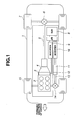
- FIG. 1 shows a schematic construction of a control apparatus according to an embodiment.
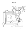
- FIG. 2A shows a schematic construction of a control system of a vehicle.
- the shown vehicle is a so-called hybrid vehicle, which is driven by at least one of a motor and an engine.
- an engine provided with at least one exhaust gas sensor and a heating device for the exhaust gas sensor is applied to a so-called hybrid vehicle having functions of automatically stopping an engine when a predetermined operating condition is satisfied and automatically restarting the engine when another predetermined operating condition is satisfied.
- a motor generator 3 is disposed between an engine 2 and a continuously variable transmission 4. Rotation of engine 2 or motor generator 3 is transmitted to drive wheels (rear wheels) 7 through the continuously variable transmission 4, a drive shaft 5, one end of which is connected to the transmission, and a differential gear 6 connected between the wheels and drive shaft.
- continuously variable transmission 4 comprises a torque converter, a forward-reverse switch mechanism and a metal belt looped between variable pulleys.
- the speed ratio through the metal belt is altered by altering the pulley ratio between the variable pulleys.
- a desired speed ratio for the continuously variable transmission 4 is set in accordance with the operating state.
- a primary oil pressure and a secondary oil pressure for actuating the variable pulleys are controlled such that the desired speed ratio agrees with the speed ratio, which represents the ratio between actual input and output rotational speeds.
- the forward-reverse switch mechanism switches the direction of output rotation between forward drive and reverse drive.
- the torque converter transmits a torque of input rotation to an output section through the action of fluid, and may stop rotation of the output section when, for example, an input section rotates extremely slowly.
- Motor generator 3 is connected directly or through a belt or a chain to a crankshaft of engine 2 to rotate in synchronization with engine 2.
- Motor generator 3 functions as an electric motor or as an electric generator.
- motor generator 3 functions as an electric motor to assist the output of engine 2, or to start the engine 2, electric current is supplied from a battery (42V battery) 8 through an inverter 9.
- battery 8 is charged by the electric current generated through inverter 9.
- motor generator 11 is provided. Rotation of motor generator 11 is transmitted to drive wheels (front wheels) 15 through a speed reduction gear 12, a drive shaft 13 and a differential gear 14. Motor generator 11 also functions as an electric motor or as an electric generator. In a similar manner to motor generator 3, when motor generator 11 functions as an electric motor, electric current is supplied from battery 8 through an inverter 16. When motor generator 11 functions as an electric generator to recycle the running energy of the vehicle, battery 8 is charged by the electric current generated through inverter 16. While a single battery 8 is illustrated there may be a plurality of batteries. Further, while two motor generators are illustrated, there could be fewer or more of such generators.
- motor generators 3 and 11 are each referred to simply as a "motor”.
- controller 21 may be called a hybrid controller.
- hybrid controller 21 may control various aspects of vehicle operation including control of acceleration, constant speed or deceleration, in cooperation with an engine controller 22, a transmission controller 23, a battery controller 24 and a motor controller 25.
- vehicle speed sensor 40 may compute the vehicle speed, on the basis of an engine rotational speed detected by an engine rotational speed sensor 32, the speed ratio of continuously variable transmission 4, etc.
- hybrid controller 21 implements a vehicle start from a state of creep running by 4WD drive.
- an assist switch 34 is provided in order to produce a predetermined acceleration when necessary.
- assist switch 34 is turned to an "ON" state by a driver, hybrid controller 21 allows the motor 11 to assist the driving effort.
- hybrid controller 21 is configured to stop the operation of engine 2 when a predetermined operating condition is satisfied while the vehicle is running, and to restart the engine 2 by motor 3 when another predetermined operating condition is satisfied after that.
- hybrid controller 21 controls the automatic stop and restart of engine 2 through engine controller 22. While two separate controllers 21 and 22 are illustrated, they may actually be combined together in some instances into a single controller.
- engine controller 22 controls the opening of a throttle valve 42 in accordance with accelerator opening and engine rotational speed, controls the quantity of fuel injected by a fuel injection valve 43 and the timing of fuel injection, and further controls an ignition timing when ignition plug 44 makes ignition sparks fly, so as to produce an engine output to provide a requested driving effort.
- engine controller 22 turns back the engine into an idle state, and then cuts off the supply of fuel from fuel injection valve 43 and also stops the operation of ignition plug 44.
- engine controller 22 restarts the supply of fuel from fuel injection valve 43 and restarts the operation of ignition plug 44.
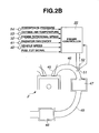
- FIG. 2B shows a schematic construction of a control system of an exhaust purifier of engine 2.
- An exhaust port 45 of engine 2 is connected to an exhaust manifold 46.
- a first catalyst (manifold catalyst) 47 is connected to a position downstream from exhaust manifold 46.
- a second catalyst (underfloor catalyst) 48 is connected to a position downstream from first catalyst 47 through an exhaust passage 49.
- two catalysts 47 and 48 are three-way catalysts.
- each of two catalysts 47 and 48 is not limited to a three-way catalyst, and may be any catalyst other than three-way catalyst, such as a NOx occlusion catalyst, according to requested exhaust performance.
- An air-fuel ratio sensor (exhaust gas sensor) 51 is installed immediately upstream of first catalyst 47. The output of air-fuel ratio sensor 51 is outputted to engine controller 22. While sensor 51 is an air-fuel ratio sensor in the illustrated approach, the discussion below applies to any form of exhaust gas sensor, including, for example, an oxygen (“O 2 ”)_sensor
- heater 52 is installed close to air-fuel ratio sensor 51 in order to shorten the period taken to reach the activation temperature.
- heater 52 is a device that generates a heat through resistance energization heating, but may be any other heater, such as a heater that carries out heating by burning fuel.
- condensation where the water vapor within exhaust manifold 46 is cooled down by outside air, adhered to the inside wall of exhaust manifold 46, and condensed into water
- condensation may occur at air-fuel ratio sensor 51 in exhaust manifold 46 while air-fuel ratio sensor 51 is being heated.
- condensation while sensor 51 is being heated such as through the use of heater 52, it is possible that the sensor 51 may be inadvertently damaged such as through subjection to a heat shock, which in turn may crack a sensor element. Accordingly, it is necessary to prevent condensation from occurring at air-fuel ratio sensor 51 under heating.
- engine controller 22 receives a variety of inputs including a subset of the following: an outside-air temperature sensed by a temperature sensor 53; the atmospheric pressure sensed by a pressure sensor 54; the engine rotational speed sensed by engine rotational speed sensor 32 as a parameter relevant to the gas exhausted to the exhaust pipe until the engine stops after the fuel supply is stopped; the operating state of a radiator fan sensed by a radiator fan operating signal sensing mechanism 41; the vehicle speed sensed by vehicle speed sensor 40; a signal relevant to fuel cut, etc.
- engine controller 22 estimates the temperature of exhaust manifold 46 (exhaust pipe temperature), Texmani; estimates a condensation occurrence temperature Tktr based on an environmental condition (including at least one of the outside-air temperature, the outside-air humidity and the atmospheric pressure); heats air-fuel ratio sensor 51 to its activation temperature by heater 52 when exhaust manifold temperature Texmani is higher than or equal to condensation occurrence temperature Tktr; and lowers heating performance of heater 52 or stops heating performed by heater 52 when exhaust manifold temperature Texmani is lower than condensation occurrence temperature Tktr during idle stop.
- exhaust manifold 46 exhaust pipe temperature
- Texmani estimates a condensation occurrence temperature Tktr based on an environmental condition (including at least one of the outside-air temperature, the outside-air humidity and the atmospheric pressure)
- heats air-fuel ratio sensor 51 to its activation temperature by heater 52 when exhaust manifold temperature Texmani is higher than or equal to condensation occurrence temperature Tktr
- condensation which occurs when the exhaust gas exhausted from cylinder to exhaust manifold 46 is cooled at an interface surface of exhaust manifold 46 by outside air such that the partial pressure of the water vapor contained in the exhaust gas exceeds the saturated water vapor pressure.
- an in-exhaust-manifold water vapor partial pressure is further calculated by an exhaust gas water vapor partial pressure calculating mechanism.
- condensation occurrence temperature Tktr is estimated.
- FIG. 3 shows, from top to bottom, models of the water vapor partial pressure of intake air, the water vapor partial pressure of exhaust gas, and the water vapor partial pressure within exhaust manifold 46 during idle stop.
- the water vapor partial pressure of exhaust gas contains a water vapor partial pressure of intake air, P1, and further a water vapor partial pressure P2 resulting from combustion.
- engine controller 22 cuts off the supply of fuel from fuel injection valve 43 to stop the engine, so that the engine stops after the engine has rotated some turns from the timing when the fuel supply is cut off.
- intake air fresh air
- Saturated water vapor pressure P0 is determined in accordance with the temperature of outside air as shown in FIGS. 4A and 4B.
- FIG. 4A shows a table of saturated water vapor pressure P0 with respect to outside-air temperature as a parameter.
- FIG. 4B shows a schematic characteristic of saturated water vapor pressure P0 with respect to outside-air temperature. As shown in FIG. 4B, saturated water vapor pressure P0 has a characteristic of decreasing with decreasing outside-air temperature.
- engine controller 22 turns throttle valve 42 back into the idle position (the engine back into idle state), and carries out combustion with the theoretical air-fuel ratio during idle state, i.e. that all of O 2 in intake air is used for combustion.
- the water vapor partial pressure resulting from combustion with the theoretical air-fuel ratio is calculated from the following chemical formula for combustion (molecular formula for gasoline combustion). CH 1.9 + 1.475 ⁇ O 2 ⁇ CO 2 + 0.95 ⁇ H 2 ⁇ O where CH 1.9 is the average molecular formula of gasoline.
- combustion gas water vapor partial pressure P2 can be determined based on the proportion of water vapor partial pressure of combustion gas, atmospheric pressure Pa, and saturated water vapor pressure P0, using the following equation.
- Exhaust gas water vapor partial pressure P3 is calculated from the following equation.
- the water vapor partial pressure is on a unit volume basis. Accordingly, as the volume increases due to combustion, the water vapor partial pressure decreases in terms of saturated water vapor pressure.
- Equation (4) is reduced as follows.
- P ⁇ 3 P ⁇ 2 + P ⁇ 1 ⁇ 0.8104
- exhaust gas water vapor partial pressure P3 is determined in accordance with atmospheric pressure Pa and saturated water vapor pressure P0.
- saturated water vapor pressure P0 is determined in accordance with the temperature of outside air. Therefore, exhaust gas water vapor partial pressure P3 is determined in accordance with atmospheric pressure Pa and the outside-air temperature, i.e. environmental conditions.
- FIG. 5A shows a table of exhaust gas water vapor pressure P3 with respect to outside-air temperature as a parameter
- FIG. 5B shows a schematic characteristic of exhaust gas water vapor pressure P3 with respect to outside-air temperature.
- the exhaust gas water vapor pressure has a characteristic of decreasing with decreasing outside-air temperature.
- In-exhaust-manifold water vapor partial pressure (the water vapor partial pressure of the gas resident within the exhaust pipe) P4 in this state is determined as follows.
- the engine is a straight four cylinder engine. Accordingly, detailed consideration is made assuming the following four conditions are preconditions.
- Condition 1 Suppose the engine rotates substantially two turns until the engine stops after the fuel supply is cut off.
- the rotation of two turns is for an engine used for an experiment. It is considered that the rotation of two turns does not hold for different engine specifications. Accordingly, the number of turns of rotation of an engine until the engine stops after the fuel supply is cut off is necessary to determine on the basis of the engine specification. In this embodiment, this is set on the assumption that the engine is a straight four cylinder engine. In general, the number of turns of rotation of an engine until the engine stops after the fuel supply is cut off intends to decrease with increasing displacement and increasing number of cylinders.
- VTC valve timing control
- IVC intake valve closing timing
- ABDC bottom dead center
- V0 is the volume of a particular cylinder and the term of V0 ⁇ (1+cosIVC[degABDC])/2 ⁇ determines the volume at intake valve closing timing IVC. Further, in equation (8), the term of (1-Boost/Pa) indicates the partial pressure ratio of intake air with respect to the atmospheric pressure.
- the water vapor partial pressure within exhaust manifold 46 can be determined as follows.
- in-exhaust-manifold water vapor partial pressure P4 is given by the following equation.
- in-exhaust-manifold water vapor partial pressure P4 is determined in accordance with saturated water vapor pressure P0 and atmospheric pressure Pa.
- saturated water vapor pressure P0 is determined in accordance with the outside-air temperature and atmospheric pressure Pa. Therefore, in-exhaust-manifold water vapor partial pressure P4 is determined in accordance with the outside-air temperature and atmospheric pressure Pa, i.e. environmental conditions.
- Equation (11) is determined assuming the above four conditions.
- in-exhaust-manifold water vapor partial pressure P4 also depends on engine specification. In summary, in-exhaust-manifold water vapor partial pressure P4 is determined in accordance with environmental conditions and engine specifications. This means that it is possible to calculate in-exhaust-manifold water vapor partial pressure P4 on the basis of environmental conditions and engine specifications.
- Temperature Tktr at or below which condensation occurs within exhaust manifold 46, is a temperature at which in-exhaust-manifold water vapor partial pressure P4 is equal to saturated water vapor pressure P0.
- condensation occurrence temperature Tktr is specifically calculated for the case where atmospheric pressure Pa is equal to 760 mmHg (101.3 kPa) and the outside-air temperature is equal to 25°C.
- saturated water vapor pressure P0 is determined to be 24.65 mmHg (3.29 kPa) using the table of FIG. 4A as follows.
- the following describes a method for estimating the exhaust manifold temperature.
- FIG. 6 outlines a process in which engine controller 22 estimates the temperature of exhaust manifold 46.
- exhaust gas flows away from the reader (i.e., into the page) on the left side.
- the quantity of heat transferred from the exhaust gas within exhaust manifold 46 to exhaust manifold 46 is represented by Qin, and the quantity of heat transferred from exhaust manifold 46 to the outside air is represented by Qout.
- heat transfer rate, hin is a heat transfer rate between exhaust manifold 46 and the exhaust gas within exhaust manifold 46, which is set, when engine 2 is rotating, to a heat transfer rate (for example, 30 kcal/m 2 hk) for the case where the exhaust gas is flowing, and is set, when engine 2 is not rotating, to a heat transfer rate (for example, 4 kcal/m 2 hk) for the case where the exhaust gas is stationary.
- Exhaust gas temperature Tin which is the temperature of the exhaust gas within exhaust manifold 46, is set as follows.
- heat transfer rate hout is a heat transfer rate between exhaust manifold 46 and the exhaust gas within exhaust manifold 46, which is set, when the vehicle is running or the radiator fan is rotating, to a heat transfer rate (for example, 10 kcal/m 2 hk) for the case where the air is flowing, and is set, when the vehicle is stationary and the radiator fan is stationary, to a heat transfer rate (for example, 4 kcal/m 2 hk) for the case where the air is stationary.
- the mass of exhaust manifold 46, M is equal to a value determined in accordance with engine specifications (for example, 5 kg).
- the specific heat of exhaust manifold 46, C is equal to a value determined in accordance with constituent materials of exhaust manifold 46. For example, in the case where the constituent material is iron, specific heat C is equal to 0.442 kJ/kgK.
- FIG. 7 shows a flow chart for calculating the exhaust manifold temperature, which is carried out at constant intervals (for example, every 10 ms).
- outside-air temperature Ta which is sensed by temperature sensor 53, is read.
- step S2 it is checked whether or not engine 2 is rotating, by comparing the rotational speed of engine 2, Ne, with zero.
- the control process proceeds to step S3, at which the heat transfer rate for the case where the exhaust gas is flowing (for example, 30 kcal/m 2 hk) is substituted into heat transfer rate hin.
- step S4 it is checked whether or not the fuel is currently cut off.
- the control process proceeds to step S5, at which pint the exhaust gas temperature (constant value) for the case where the engine rotates at idle speed is substituted into exhaust gas temperature Tin.
- step S5 the control process proceeds from step S4 to step S6, at which outside-air temperature Ta is directly substituted into exhaust gas temperature Tin.
- This equation expresses that the exhaust gas within exhaust manifold 46 is heated by the quantity of heat transferred from exhaust manifold 46.
- the initial value of Tin (preceding) is set equal to the intake air temperature (equal to outside-air temperature Ta).
- step S9 the quantity of heat transferred from the exhaust gas within exhaust manifold 46 to exhaust manifold 46, Qin, is calculated by the above equation (12).
- step S10 it is checked whether or not the vehicle is stationary and the radiator fan is stationary, on the basis of the signals of the vehicle speed and the radiator fan switch.
- the control process proceeds to step S12, at which the heat transfer rate for the case where the exhaust gas is stationary (for example, 4 kcal/m 2 hk) is substituted into heat transfer rate hout.
- the control process proceeds from step S10 to step S11, at which the heat transfer rate for the case where the air is flowing (for example, 10 kcal/m 2 hk) is substituted into heat transfer rate hout.
- step S13 the quantity of heat transferred from exhaust manifold 46 to the outside air, Qout, is calculated by the following equation.
- Qout hout ⁇ Texmani preceding - Ta
- step S14 exhaust manifold temperature Texmani is calculated based on the two heat quantities Qin and Qout thus obtained at steps S9 and S13 by using the above equation (14).
- step S15 the value of exhaust manifold temperature Texmani is substituted into exhaust manifold temperature Texmani (preceding) which represents the preceding value of the exhaust manifold temperature. After that, the current process ends.
- FIG. 8 shows a flow chart for carrying out a sensor heating control process during idle stop, which is carried out at constant intervals (for example, every 10 ms) subsequent to the flow chart of FIG. 7.
- step S21 it is checked whether or not engine 2 is rotating, by comparing the rotational speed of engine 2, Ne, with zero.
- the control process proceeds to step S22, at which an engine operation flag ENGRUN is set equal to 1.
- the control process proceeds to step S23, at which engine operation flag ENGRUN is set equal to 0.
- step S24 engine operation flag ENGRUN is checked.
- engine operation flag ENGRUN is equal to 1, the process ends immediately.
- step S25 At which outside-air temperature Ta sensed by temperature sensor 53, atmospheric pressure Pa sensed by pressure sensor 54, and exhaust manifold temperature Texmani calculated at step S14 of FIG. 7, are read.
- saturated water vapor pressure P0 is calculated by searching the table of FIG. 4A based on outside-air temperature Ta. If the outside-air temperature is not equal to a standard outside-air temperature, such as 0°C, 10°C, 20°C or 100°C, saturated water vapor pressure P0 is calculated by using linear interpolation equations.
- the saturated water vapor pressure is calculated, that is, the water vapor partial pressure of intake air for the case where the humidity of the outside air is equal to 100% is calculated, because the embodiment is targeted to the case where there no humidity sensor is provided for sensing the humidity of the outside air.
- the disclosure is only by way of example and is not limited to this case.
- a map of intake air water vapor partial pressure P1 which is determined in accordance with the temperature and humidity of outside air may be prepared in memory within engine controller 22; intake air water vapor partial pressure P1 may be determined by searching the map on the basis of the temperature and humidity of outside air sensed by the sensors; and the saturated water vapor pressure P0 may be used instead of intake air water vapor partial pressure P1.
- in-exhaust-manifold water vapor partial pressure P4 is calculated on the basis of saturated water vapor pressure P0 and atmospheric pressure Pa by the following equation, which is identical to the above equation (11).
- P ⁇ 4 P ⁇ 0 ⁇ 0.8412 + Pa ⁇ 0.1059
- step S28 the temperature at which the thus-determined in-exhaust-manifold water vapor partial pressure P4 is equal to saturated water vapor pressure P0, i.e. condensation occurrence temperature Tktr, is calculated.
- Condensation occurrence temperature Tktr can be determined as explained above in accordance with the section including the notation ⁇ 5>.
- step S29 exhaust manifold temperature Texmani and condensation occurrence temperature Tktr are compared with each other.
- the control process proceeds to step S30, at which point electric power supply to heater 52 is stopped or otherwise adjusted downwardly. This is because when condensation occurs in air-fuel ratio sensor 51, which is heated to the activation temperature, a heat shock may result, potentially resulting in the undesirable cracking of a sensor element, and because this is to be prevented.
- the electric power supply to heater 52 is stopped.
- the heating performance of heater 52 for air-fuel ratio sensor 51 may be lowered by lowering the supply power to heater 52, and air-fuel ratio sensor 51 may be heated with such a level that potential damage such as a heat shock is not caused even when condensation occurs in air-fuel ratio sensor 51.
- step S31 at which air-fuel ratio sensor 51 is heated to a target temperature by operating the heater 52 by supplying electric power to heater 52.
- a vehicle which has the functions of performing an idle stop (automatically stops engine 2) when an idle stop permission condition (a predetermined operating condition) is satisfied while the vehicle is running, and automatically restarting engine 2 when the idle stop permission condition is unsatisfied (when another predetermined operating condition is satisfied)
- an idle stop permission condition a predetermined operating condition
- a hybrid vehicle one or more exhaust gas sensors and an associated heater 52 (heating device) are provided.
- a hybrid vehicle is not necessary.
- Condensation occurrence temperature Tktr is estimated as discussed above based on environmental conditions as well as known engine specifications, during idle stop (when the engine is automatically stopped) (refer to steps S24 and S28 of FIG.
- the controlling of heater 52 prevents a situation where even while condensation occurs within exhaust manifold 46 (exhaust pipe), unacceptable levels of electric power is supplied to heater 52, and a situation where even while condensation does not occur within exhaust manifold 46, electric power is not supplied to heater 52, during idle stop.
- Condensation occurrence temperature Tktr is a temperature at which in-exhaust-manifold water vapor partial pressure P4 (the water vapor partial pressure of a gas which resides within the exhaust pipe) is equal to saturated water vapor pressure P0 during idle stop. This enables to calculate precisely condensation occurrence temperature Tktr.
- in-exhaust-manifold water vapor partial pressure P4 during idle stop is calculated based on exhaust gas water vapor partial pressure P3 in the idle state and based on the water vapor partial pressure of an intake air, which is exhausted to exhaust manifold 46 by rotation of the engine after the fuel supply is cut off, P1 (refer to the above equation (10)).
- P1 the water vapor partial pressure of an intake air, which is exhausted to exhaust manifold 46 by rotation of the engine after the fuel supply is cut off
- the quantity of intake air that is exhausted to exhaust manifold 46 by rotation of the engine after the fuel supply is cut off is determined in accordance with the intake pressure and the number of turns of the engine after the fuel supply is cut off.
- the quantity of intake air which is exhausted to exhaust manifold 46 by rotation of the engine after the fuel supply is cut off, Vaex is calculated based on intake pressure, Boost, and based on the number of turns of the engine after the fuel supply is cut off (the number of turns of the engine until the engine stops after the fuel supply is cut off) (refer to the above equations (8) and (9)).
- the quantity of intake air, which is exhausted to exhaust manifold 46 by rotation of the engine after the fuel supply is cut off is determined in accordance with intake valve closing timing, IVC, at idle state immediately before fuel supply is cut off, because the cylinder intake capacity varies in accordance with intake valve closing timing IVC.
- the quantity of intake air that is exhausted to exhaust manifold 46 by rotation of the engine after the fuel supply is cut off, Vaex is calculated also based on intake valve closing timing IVC at idle state immediately before fuel supply is cut off (refer to the above equations (8) and (9)). This enables the precise calculation of the quantity of intake air that is exhausted to exhaust manifold 46 by rotation of the engine after the fuel supply is cut off, Vaex, for different intake valve closing timings, IVC, at idle state immediately before fuel supply is cut off.
- in-exhaust-manifold water vapor partial pressure P4 (the water vapor partial pressure of the gas which resides within the exhaust pipe) is calculated based on atmospheric pressure, Pa, which is sensed by pressure sensor 54 (refer to the above equation (11)). This enables to calculate precisely in-exhaust-manifold water vapor partial pressure P4 for different atmospheric pressures Pa.
- condensation occurrence temperature, Tktr is a temperature at which water vapor partial pressure, P4, is equal to saturated water vapor pressure, P0,in the gas which resides within the exhaust pipe when the engine is automatically stopped
- condensation occurrence temperature, Tktr is a temperature at which water vapor partial pressure, P3, is equal to saturated water vapor pressure, P0, in exhaust gas is possible.
- Step S28 of FIG. 8 implements a condensation occurrence temperature estimation processing step.
- Steps S29 to S31 of FIG. 8 implement a heating control processing step.
- Step S28 of FIG. 8 implements the function of condensation occurrence temperature estimation means.
- Steps S29 to S31 of FIG. 8 implement the function of heating control means.
- Step S27 of FIG. 8 implements exhaust gas water vapor partial pressure calculation means.
Landscapes
- Engineering & Computer Science (AREA)
- Chemical & Material Sciences (AREA)
- Combustion & Propulsion (AREA)
- Mechanical Engineering (AREA)
- General Engineering & Computer Science (AREA)
- Combined Controls Of Internal Combustion Engines (AREA)
- Control Of Vehicle Engines Or Engines For Specific Uses (AREA)
- Electrical Control Of Air Or Fuel Supplied To Internal-Combustion Engine (AREA)
- Exhaust Gas After Treatment (AREA)
Abstract
Description
- The present invention relates to vehicle control and particularly, but not exclusively, to a method and apparatus for heating an exhaust gas sensor to an activation temperature. Aspects of the invention also relate to a vehicle.
- In some engines, exhaust gas sensors, such as an air-fuel ratio sensor for sensing the air-fuel ratio of exhaust gas and an O2 sensor for sensing the oxygen concentration, are attached to exhaust passages such as exhaust pipes. In order for such an exhaust gas sensor to output a normal and accurate sensing signal, it is generally necessary to raise the temperature of the exhaust gas sensor to an activation temperature. In such a case, an exhaust gas sensor is heated by a separate heating device such as a heater, because it takes a long time to solely heat an exhaust gas sensor by the heat contained in exhaust gas and passing through the exhaust passages.
- On the other hand, in such an engine as an exhaust gas sensor is heated by a distinct heating device such as a heater, when condensation (where water vapor within an exhaust pipe is cooled down by outside air, and condensed into water) occurs at the exhaust gas sensor positioned in an exhaust passage while the exhaust gas sensor is being heated, it is possible that a heat shock may be caused in the exhaust gas sensor resulting in undesirable failure such as through cracking of a critical element of the sensor.
- Accordingly, in
Japanese Patent No. 3636047 - According the
Japanese Patent No. 3636047 - In the above-described engine, which is provided with an exhaust gas sensor and a separate heating device, the threshold temperature below which condensation occurs within an exhaust passage such as an exhaust pipe depends significantly on environmental conditions such as the temperature and humidity of outside air and the atmospheric pressure, and on engine specifications.
- However, where the condensation occurrence temperature is set to a substantially constant value, such as the case according to the technique of
Japanese Patent No. 3636047 - The problem is aggravated in a so-called hybrid vehicle which has the functions of automatically stopping an engine when a predetermined operating condition is satisfied and automatically restarting the engine when another predetermined operating condition is satisfied, and which drives the vehicle with at least one of a motor and the engine. In such a hybrid vehicle, which is provided with the exhaust gas sensor and the heating device, it is impossible to judge precisely whether or not condensation occurs within an exhaust passage by setting the condensation occurrence temperature to a substantially constant value. This causes a situation where even while condensation occurs within the exhaust pipe, an exhaust gas sensor is heated to its activation temperature by a heating device, and a situation where even while condensation does not occur within the exhaust pipe, the heating performed by the heating device is stopped. As a result, the durability of the exhaust gas sensor decreases significantly, and the quantity of deleterious components within engine generated exhaust increases due to a delay in the start of feedback control of an air-fuel ratio within the engine.
- It is an aim of the invention to address this issue. Embodiments of the invention may ensure compatibility between activation of an exhaust gas sensor and prevention of heat shock to the exhaust gas sensor by precisely controlling operation of a separate heating device associated with the sensor such as that employed in a vehicle which includes the functions of automatically stopping an engine when a predetermined operating condition is satisfied, and automatically restarting the engine when another predetermined operating condition is satisfied (e.g., a hybrid vehicle). Other aims and advantages of the invention will become apparent from the following description, claims and drawings.
- Aspects of the invention therefore provide an apparatus, a method and a vehicle as claimed in the appended claims.
- According to another aspect of the invention there is provided a vehicle control apparatus for a vehicle, which includes an engine having at least one exhaust gas sensor associated with an exhaust passage of the engine for sensing a property of an exhaust gas, and a heater for heating the exhaust gas sensor, wherein the engine is selectively controlled to stop automatically when a predetermined operation condition is satisfied, the vehicle control apparatus comprising an environmental condition sensing mechanism that senses, when an engine is automatically stopped, at least one environmental condition, the at least one environmental condition including at least one of an atmospheric temperature and an atmospheric pressure and a controller, wherein the controller includes a condensation occurrence temperature estimation mechanism that estimates a condensation occurrence temperature based on the at least one environmental condition and based on a parameter related to a gas that is selectively exhausted to an exhaust passage until the engine stops rotation after a fuel supply of the engine is cut off and a heating control mechanism that selectively heats an exhaust gas sensor to a desired activation temperature with a heater if a temperature of the exhaust passage is higher than or equal to the condensation occurrence temperature when the engine is automatically stopped, and selectively performs, if the exhaust passage temperature is lower than the condensation occurrence temperature when the engine is automatically stopped, one of lowering heating performance of the heater and stopping the heating performed by the heater.
- In an embodiment, the controller selectively determines a water vapor partial pressure in the exhaust passage, and wherein the condensation occurrence temperature is set to a temperature at which the water vapor partial pressure is equal to or substantially equal to a saturated water vapor pressure.
- In an embodiment, the controller further includes an exhaust gas water vapor partial pressure calculation mechanism, the exhaust gas water vapor partial pressure calculation mechanism selectively calculates a water vapor partial pressure of a gas that resides within the exhaust passage when the engine is automatically stopped, and wherein the condensation occurrence temperature is set to a temperature at which the water vapor partial pressure is equal to or substantially equal to a saturated water vapor pressure.
- In an embodiment, the exhaust gas water vapor partial pressure calculation mechanism calculates, if the engine is stopped by cutting off the fuel supply when the engine is in an idle state, the water vapor partial pressure of the gas that resides within the exhaust passage, based on a water vapor partial pressure of exhaust gas in the idle state and based on a water vapor partial pressure of an intake air that is exhausted to the exhaust passage by rotation of the engine after the fuel supply is cut off.
- In an embodiment, the exhaust gas water vapor partial pressure calculation mechanism selectively calculates a quantity of the intake air that is exhausted to the exhaust passage by rotation of the engine after the fuel supply is cut off based on an intake pressure and based on the number of turns of the engine after the fuel supply is cut off.
- In an embodiment, the exhaust gas water vapor partial pressure calculation mechanism calculates the quantity of the intake air that is exhausted to the exhaust passage by rotation of the engine after the fuel supply is cut off based on an intake valve closing timing at the idle state immediately before the fuel supply is cut off.
- The apparatus may comprise a temperature sensor for sensing an outside-air temperature and a humidity sensing mechanism for sensing an outside-air humidity, wherein the exhaust gas water vapor partial pressure calculation mechanism performs the calculation of a water vapor partial pressure of an intake air that is drawn into the engine, based on the outside-air temperature and humidity and the calculation of the water vapor partial pressure of the gas that resides within the exhaust passage, based on the water vapor partial pressure of the intake air.
- In an embodiment, the humidity sensing mechanism is a physical sensor and the exhaust gas water vapor partial pressure calculation mechanism calculates, when the physical sensor has a failure, the water vapor partial pressure of intake air based on the sensed outside-air temperature on the assumption that the outside-air humidity is equal to or substantially equal to 100%.
- The apparatus may comprise a temperature sensor for sensing an outside-air temperature, wherein the exhaust gas water vapor partial pressure calculation mechanism calculates a water vapor partial pressure of an intake air based on the sensed outside-air temperature on the assumption that an outside-air humidity is equal to or substantially equal to 100% and calculates the water vapor partial pressure of the gas, which resides within the exhaust passage, based on the water vapor partial pressure of the intake air.
- The apparatus may comprise an atmospheric pressure sensor for sensing the atmospheric pressure, wherein the exhaust gas water vapor partial pressure calculation mechanism calculates a water vapor partial pressure of exhaust gas based on the sensed atmospheric pressure and calculates the water vapor partial pressure of the gas which resides within the exhaust passage, based on the water vapor partial pressure of exhaust gas.
- According to another aspect of the invention there is provided a vehicle control method for a vehicle which includes an engine including an exhaust gas sensor associated with an exhaust passage of the engine for sensing a property of exhaust gas, and a heating device for heating the exhaust gas sensor, which when a predetermined operating condition is satisfied, automatically stops the engine, and which when another predetermined operating condition is satisfied, automatically restarts the engine, the vehicle control method comprising detecting at least one environmental condition when an engine is automatically stopped, estimating a condensation occurrence temperature based on the at least one environmental condition and based on a parameter related to a gas that is selectively exhausted to an exhaust passage until the engine stops rotation after a fuel supply of the engine is cut off and selectively heating the exhaust gas sensor to an activation temperature by an heating device if a temperature of an exhaust passage of the engine is higher than or equal to the condensation occurrence temperature when the engine is automatically stopped, and selectively performing, if the exhaust passage temperature is lower than the condensation occurrence temperature when the engine is automatically stopped, one of lowering heating performance of the heating device and stopping the heating performed by the heating device.
- The method may comprise determining a water vapor pressure in a gas residing within the exhaust passage when the engine is automatically stopped and setting the condensation occurrence temperature to a temperature at which the water vapor partial pressure is equal to or substantially equal to a saturated water vapor pressure.
- In an embodiment, if the engine is automatically stopped by cutting off fuel supply when the engine is in an idle state, the water vapor partial pressure of the gas residing within the exhaust passage being determined based on a water vapor partial pressure of exhaust gas in the idle state and based on a water vapor partial pressure of an intake air which is exhausted to the exhaust passage by rotation of the engine after the fuel supply is cut off.
- The method may comprise calculating a quantity of the intake air that is exhausted to the exhaust passage by rotation of the engine after the fuel supply is cut off based on an intake pressure and based on the number of turns of the engine after the fuel supply is cut off.
- The method may comprise calculating a water vapor partial pressure of intake air based an outside-air temperature and an outside-air humidity and calculating the water vapor partial pressure of the gas that resides within the exhaust passage, based on the water vapor partial pressure of intake air.
- In an embodiment, when the outside-air humidity cannot be detected, the water vapor partial pressure of intake air is calculated on the assumption that the outside-air humidity is equal to or substantially equal to 100%.
- The method may comprise calculating a water vapor partial pressure of intake air based on an outside-air temperature on the assumption that an outside-air humidity is equal to or substantially equal to 100% and calculating the water vapor partial pressure of the gas that resides within the exhaust passage, based on the water vapor partial pressure of intake air.
- According to a further aspect of the invention there is provided a vehicle control apparatus for a vehicle, which includes an engine having at least one exhaust gas sensor associated with an exhaust passage of the engine for sensing a property of an exhaust gas, and a heater for heating the exhaust gas sensor, the engine is selectively controlled to stop automatically when a predetermined operation condition is satisfied, the vehicle control apparatus comprising an environmental condition sensing section that senses at least one environmental condition when an engine is automatically stopped, the at least one environmental condition including at least one of an atmospheric temperature and an atmospheric pressure and a condensation occurrence temperature estimation section that estimates a condensation occurrence temperature based on the at least one environmental condition and based on a parameter related to a gas that is selectively exhausted to an exhaust passage until the engine stops rotation after a fuel supply of the engine is cut off and a heating control section that selectively heats an exhaust gas sensor with a heater when the engine is automatically stopped, in which the heater is selectively controlled to heat the exhaust gas sensor to a desired activation temperature if a temperature of the exhaust passage is higher than or equal to the condensation occurrence temperature, and the heater is selectively controlled to lower or stop a heating performance thereof if the exhaust passage temperature is lower than the condensation occurrence temperature.
- According to a still further aspect of the invention there is provided a vehicle control apparatus for a vehicle, which includes an engine, wherein the engine is selectively controlled to stop automatically when a predetermined condition is satisfied, having at least one exhaust gas sensor associated with an exhaust passage of the engine for sensing a property of an exhaust gas, and a heating device for heating the exhaust gas sensor, the vehicle control apparatus comprising an environmental condition sensing means for sensing, when the engine is automatically stopped, at least one environmental condition, the at least one environmental condition including at least one of the atmospheric temperature and the atmospheric pressure and a controller means, wherein the controller means includes a condensation occurrence temperature estimation means for estimating a condensation occurrence temperature based both on a parameter related to a gas that is selectively exhausted to the exhaust passage and also based on the at least one environmental condition and a heating control means for selectively heating the exhaust gas sensor to a desired activation temperature using the heating device if a temperature of the exhaust passage is higher than or equal to the condensation occurrence temperature, and selectively performs, if the exhaust passage temperature is lower than the condensation occurrence temperature when the engine is automatically stopped, one of lowering heating performance of the heating device and stopping the heating performed by the heating device.
- For example, a vehicle control apparatus for a vehicle may include an engine with an exhaust gas sensor attached to an exhaust passage of the engine for sensing a property of exhaust gas and a heating device for heating the exhaust gas sensor. In the case of a hybrid vehicle when a predetermined operating condition is satisfied, the engine automatically stops. When another predetermined operating condition is satisfied the engine automatically restarts. The vehicle control apparatus includes an environmental condition sensing mechanism for sensing when the engine is automatically stopped. The vehicle control apparatus further includes a controller, wherein the controller includes a condensation occurrence temperature estimation mechanism for estimating a condensation occurrence temperature based on a specification of the engine and based on the environmental condition. Moreover, the vehicle control apparatus includes a heating controller associated with a heating device capable of heating an associated exhaust gas sensor to its activation temperature by the heating device if a temperature of the exhaust passage is higher than or equal to the condensation occurrence temperature when the engine is automatically stopped, and performing, if the exhaust passage temperature is lower than the condensation occurrence temperature when the engine is automatically stopped, one of lowering heating performance of the heating device and stopping the heating performed by the heating device.
- In embodiments of the invention, it may be possible to ensure compatibility between activation of an exhaust gas sensor and prevention of heat shock of the exhaust gas sensor by precisely controlling operation of a heating device associated with the sensor, particularly in a hybrid type vehicle which includes the functions of automatically stopping an engine when a predetermined operating condition is satisfied, and automatically restarting the engine when another predetermined operating condition is satisfied.
- Within the scope of this application it is envisaged that the various aspects, embodiments, examples, features and alternatives set out in the preceding paragraph, in the claims and/or in the following description may be taken individually or in any combination thereof.
- The present invention will now be described, by way of example only, with reference to the accompanying drawings in which:
- FIG. 1 is a schematic construction diagram of a vehicle control apparatus according to a first embodiment;
- FIG. 2A is a schematic construction diagram of a vehicle control system according to the first embodiment;
- FIG. 2B is a schematic construction diagram of a control system of an exhaust purifier;
- FIG. 3 is a diagram showing models of the water vapor partial pressure of intake air, the water vapor partial pressure of exhaust gas, and the water vapor partial pressure within an exhaust manifold during idle stop;
- FIGS. 4A and 4B are a table and a characteristic diagram of saturated water vapor pressure, respectively;
- FIGS. 5A and 5B are a table and a characteristic diagram of the water vapor pressure of exhaust gas, respectively;
- FIG. 6 is an outline diagram of a process for estimating exhaust manifold temperature;
- FIG. 7 is a flow chart for describing a determination of exhaust manifold temperature; and
- FIG. 8 is a flow chart for describing sensor heating control during idle stop.
- Referring to FIG. 1, this shows a schematic construction of a control apparatus according to an embodiment. FIG. 2A shows a schematic construction of a control system of a vehicle.
- The shown vehicle is a so-called hybrid vehicle, which is driven by at least one of a motor and an engine. In this embodiment, an engine provided with at least one exhaust gas sensor and a heating device for the exhaust gas sensor is applied to a so-called hybrid vehicle having functions of automatically stopping an engine when a predetermined operating condition is satisfied and automatically restarting the engine when another predetermined operating condition is satisfied.
- As shown in FIGS. 1 and 2A, a
motor generator 3 is disposed between anengine 2 and a continuouslyvariable transmission 4. Rotation ofengine 2 ormotor generator 3 is transmitted to drive wheels (rear wheels) 7 through the continuouslyvariable transmission 4, adrive shaft 5, one end of which is connected to the transmission, and adifferential gear 6 connected between the wheels and drive shaft. - For example, continuously
variable transmission 4 comprises a torque converter, a forward-reverse switch mechanism and a metal belt looped between variable pulleys. The speed ratio through the metal belt is altered by altering the pulley ratio between the variable pulleys. A desired speed ratio for the continuouslyvariable transmission 4 is set in accordance with the operating state. A primary oil pressure and a secondary oil pressure for actuating the variable pulleys are controlled such that the desired speed ratio agrees with the speed ratio, which represents the ratio between actual input and output rotational speeds. - The forward-reverse switch mechanism switches the direction of output rotation between forward drive and reverse drive. The torque converter transmits a torque of input rotation to an output section through the action of fluid, and may stop rotation of the output section when, for example, an input section rotates extremely slowly.
-
Motor generator 3 is connected directly or through a belt or a chain to a crankshaft ofengine 2 to rotate in synchronization withengine 2.Motor generator 3 functions as an electric motor or as an electric generator. Whenmotor generator 3 functions as an electric motor to assist the output ofengine 2, or to start theengine 2, electric current is supplied from a battery (42V battery) 8 through aninverter 9. Whenmotor generator 3 functions as an electric generator to recycle a running energy of the vehicle,battery 8 is charged by the electric current generated throughinverter 9. - On the other hand, another
motor generator 11 is provided. Rotation ofmotor generator 11 is transmitted to drive wheels (front wheels) 15 through aspeed reduction gear 12, adrive shaft 13 and adifferential gear 14.Motor generator 11 also functions as an electric motor or as an electric generator. In a similar manner tomotor generator 3, whenmotor generator 11 functions as an electric motor, electric current is supplied frombattery 8 through aninverter 16. Whenmotor generator 11 functions as an electric generator to recycle the running energy of the vehicle,battery 8 is charged by the electric current generated throughinverter 16. While asingle battery 8 is illustrated there may be a plurality of batteries. Further, while two motor generators are illustrated, there could be fewer or more of such generators. - Hereinafter,
motor generators - As shown in FIG. 2A, signals are inputted from an
accelerator sensor 31 and avehicle speed sensor 40 to acontroller 21. For a hybrid vehicle,controller 21 may be called a hybrid controller. On the basis of inputs fromsensors hybrid controller 21 may control various aspects of vehicle operation including control of acceleration, constant speed or deceleration, in cooperation with anengine controller 22, atransmission controller 23, abattery controller 24 and amotor controller 25. Incidentally,vehicle speed sensor 40 may compute the vehicle speed, on the basis of an engine rotational speed detected by an enginerotational speed sensor 32, the speed ratio of continuouslyvariable transmission 4, etc. - Four wheel drive ("4WD") is possible by separately transmitting driving efforts to
front wheels 15 andrear wheels 7. Accordingly, when a4WD switch 33 provided in a passenger compartment of a vehicle is turned to an "ON" state,hybrid controller 21 implements a vehicle start from a state of creep running by 4WD drive. - Further, an
assist switch 34 is provided in order to produce a predetermined acceleration when necessary. When assistswitch 34 is turned to an "ON" state by a driver,hybrid controller 21 allows themotor 11 to assist the driving effort. - On the other hand, in order to stop automatically engine 2 (idle stop) when a predetermined operating condition (idle stop permission condition) is satisfied while the vehicle is running, and to automatically restart
engine 2 when another predetermined operating condition is satisfied (when the idle stop permission condition is unsatisfied) after that,hybrid controller 21 is configured to stop the operation ofengine 2 when a predetermined operating condition is satisfied while the vehicle is running, and to restart theengine 2 bymotor 3 when another predetermined operating condition is satisfied after that. Incidentally, the idle stop permission condition does not include a condition that the vehicle speed = 0 km/h and a brake is operating. That is, the system is configured such that the engine is automatically stopped even while the vehicle is running, and restarted after the engine automatic stop also while the vehicle is running. - Accordingly, signals are inputted into
hybrid controller 21 from ashift position sensor 36 for continuouslyvariable transmission 4, anintake pressure sensor 38, asteering angle sensor 39, etc., in addition toaccelerator sensor 31 and enginerotational speed sensor 32. On the basis of those,hybrid controller 21 controls the automatic stop and restart ofengine 2 throughengine controller 22. While twoseparate controllers - While
engine 2 is operating,engine controller 22 controls the opening of athrottle valve 42 in accordance with accelerator opening and engine rotational speed, controls the quantity of fuel injected by afuel injection valve 43 and the timing of fuel injection, and further controls an ignition timing when ignition plug 44 makes ignition sparks fly, so as to produce an engine output to provide a requested driving effort. When receiving a command of engine automatic stop fromhybrid controller 21,engine controller 22 turns back the engine into an idle state, and then cuts off the supply of fuel fromfuel injection valve 43 and also stops the operation ofignition plug 44. When receiving a command of engine restart fromhybrid controller 21 after that,engine controller 22 restarts the supply of fuel fromfuel injection valve 43 and restarts the operation ofignition plug 44. - FIG. 2B shows a schematic construction of a control system of an exhaust purifier of
engine 2. - An
exhaust port 45 ofengine 2 is connected to anexhaust manifold 46. A first catalyst (manifold catalyst) 47 is connected to a position downstream fromexhaust manifold 46. Further, a second catalyst (underfloor catalyst) 48 is connected to a position downstream fromfirst catalyst 47 through anexhaust passage 49. For example, twocatalysts catalysts - An air-fuel ratio sensor (exhaust gas sensor) 51 is installed immediately upstream of
first catalyst 47. The output of air-fuel ratio sensor 51 is outputted toengine controller 22. Whilesensor 51 is an air-fuel ratio sensor in the illustrated approach, the discussion below applies to any form of exhaust gas sensor, including, for example, an oxygen ("O2")_sensor - Here, in order for air-
fuel ratio sensor 51 to output a normal and accurate sensing signal, it is necessary to raise the temperature of air-fuel ratio sensor 51 to at least its activation temperature. Although it is possible to raise the temperature of air-fuel ratio sensor 51 to its activation temperature by using exhaust heat fromengine 2 as generated through normal engine operation, such an approach is inefficient and typically time consuming. Thus, a separate heater (heating device) 52 is installed close to air-fuel ratio sensor 51 in order to shorten the period taken to reach the activation temperature. In the illustratedembodiment heater 52 is a device that generates a heat through resistance energization heating, but may be any other heater, such as a heater that carries out heating by burning fuel. - When in such an engine provided with air-
fuel ratio sensor 51 andheater 52, condensation (where the water vapor withinexhaust manifold 46 is cooled down by outside air, adhered to the inside wall ofexhaust manifold 46, and condensed into water) may occur at air-fuel ratio sensor 51 inexhaust manifold 46 while air-fuel ratio sensor 51 is being heated. When condensation whilesensor 51 is being heated such as through the use ofheater 52, it is possible that thesensor 51 may be inadvertently damaged such as through subjection to a heat shock, which in turn may crack a sensor element. Accordingly, it is necessary to prevent condensation from occurring at air-fuel ratio sensor 51 under heating. - Accordingly,
engine controller 22 receives a variety of inputs including a subset of the following: an outside-air temperature sensed by atemperature sensor 53; the atmospheric pressure sensed by apressure sensor 54; the engine rotational speed sensed by enginerotational speed sensor 32 as a parameter relevant to the gas exhausted to the exhaust pipe until the engine stops after the fuel supply is stopped; the operating state of a radiator fan sensed by a radiator fan operatingsignal sensing mechanism 41; the vehicle speed sensed byvehicle speed sensor 40; a signal relevant to fuel cut, etc. On the basis of the various inputs,engine controller 22 estimates the temperature of exhaust manifold 46 (exhaust pipe temperature), Texmani; estimates a condensation occurrence temperature Tktr based on an environmental condition (including at least one of the outside-air temperature, the outside-air humidity and the atmospheric pressure); heats air-fuel ratio sensor 51 to its activation temperature byheater 52 when exhaust manifold temperature Texmani is higher than or equal to condensation occurrence temperature Tktr; and lowers heating performance ofheater 52 or stops heating performed byheater 52 when exhaust manifold temperature Texmani is lower than condensation occurrence temperature Tktr during idle stop. - In the illustrated embodiment, attention is focused on that condensation, which occurs when the exhaust gas exhausted from cylinder to
exhaust manifold 46 is cooled at an interface surface ofexhaust manifold 46 by outside air such that the partial pressure of the water vapor contained in the exhaust gas exceeds the saturated water vapor pressure. On the basis of the exhaust gas quantity, exhaust gas temperature, specific heat, heat transfer rate, etc. of the gas exhausted to the exhaust pipe during idle stop until the engine stops after the fuel supply is stopped in the engine, an in-exhaust-manifold water vapor partial pressure is further calculated by an exhaust gas water vapor partial pressure calculating mechanism. On the basis of the in-exhaust-manifold water vapor partial pressure during idle stop, condensation occurrence temperature Tktr is estimated. - In the following, concepts regarding the in-exhaust-manifold water vapor partial pressure during idle stop are described with reference to FIG. 3, and then a method for estimating condensation occurrence temperature Tktr is described.
- FIG. 3 shows, from top to bottom, models of the water vapor partial pressure of intake air, the water vapor partial pressure of exhaust gas, and the water vapor partial pressure within
exhaust manifold 46 during idle stop. As shown in FIG. 3, the water vapor partial pressure of exhaust gas contains a water vapor partial pressure of intake air, P1, and further a water vapor partial pressure P2 resulting from combustion. At idle stop,engine controller 22 cuts off the supply of fuel fromfuel injection valve 43 to stop the engine, so that the engine stops after the engine has rotated some turns from the timing when the fuel supply is cut off. As a result, after the fuel supply is cut off, intake air (fresh air) flows into cylinders by coasting rotation of the engine and directly flows out toexhaust manifold 46. Accordingly, when the engine is in a stop state, the water vapor partial pressure of exhaust gas, and the water vapor partial pressure of intake air exhausted after the fuel supply is cut off, are mixed inexhaust manifold 46. - The following specifically describes the water vapor partial pressure of intake air, P1, the water vapor partial pressure resulting from combustion, P2, the water vapor partial pressure of exhaust gas, P3, the water vapor partial pressure within
exhaust manifold 46, P4, and condensation occurrence temperature Tktr, in the same order. - Condensation tends to occur within
exhaust manifold 46 under the condition of high water vapor partial pressure. Accordingly, as an example, a case is assumed in which the humidity of intake air (the humidity of outside air) is equal to 100%. That is, saturated water vapor pressure P0 is used as intake air water vapor partial pressure P1 as follows.
- Saturated water vapor pressure P0 is determined in accordance with the temperature of outside air as shown in FIGS. 4A and 4B. FIG. 4A shows a table of saturated water vapor pressure P0 with respect to outside-air temperature as a parameter. FIG. 4B shows a schematic characteristic of saturated water vapor pressure P0 with respect to outside-air temperature. As shown in FIG. 4B, saturated water vapor pressure P0 has a characteristic of decreasing with decreasing outside-air temperature.
- It is assumed that before idle stop,
engine controller 22 turns throttlevalve 42 back into the idle position (the engine back into idle state), and carries out combustion with the theoretical air-fuel ratio during idle state, i.e. that all of O2 in intake air is used for combustion. The water vapor partial pressure resulting from combustion with the theoretical air-fuel ratio is calculated from the following chemical formula for combustion (molecular formula for gasoline combustion).
where CH1.9 is the average molecular formula of gasoline. - According to formula (2), 1.475mol oxygen O2 is necessary to generate 0.95 mol water vapor. Since the air contains 20.95% oxygen O2, the number of moles of air necessary to draw 1.475 mol oxygen O2 is 7.041 mol as follows.

- Under the assumption that only oxygen O2 contributes to combustion, the number of moles of inert gases is 5.566 mol as follows.

- Hence, the water vapor partial pressure of combustion gas, P2, is determined as follows.

- Therefore, combustion gas water vapor partial pressure P2 can be determined based on the proportion of water vapor partial pressure of combustion gas, atmospheric pressure Pa, and saturated water vapor pressure P0, using the following equation.

- Exhaust gas water vapor partial pressure P3 is calculated from the following equation.

- Here, the water vapor partial pressure is on a unit volume basis. Accordingly, as the volume increases due to combustion, the water vapor partial pressure decreases in terms of saturated water vapor pressure. The correction factor for increase in exhaust volume in the above equation (4) is provided for this consideration, and has a value of less than 1.0 as follows.

- Hence, equation (4) is reduced as follows.

- The above equations (1) and (3) are substituted into equation (5).

- According to equation (6), exhaust gas water vapor partial pressure P3 is determined in accordance with atmospheric pressure Pa and saturated water vapor pressure P0. On the other hand, saturated water vapor pressure P0 is determined in accordance with the temperature of outside air. Therefore, exhaust gas water vapor partial pressure P3 is determined in accordance with atmospheric pressure Pa and the outside-air temperature, i.e. environmental conditions.
- According to equation (6), for example, when atmospheric pressure Pa is 760 mmHg (101.3 kPa), exhaust gas water vapor partial pressure P3 is given by the following equations.


- Since saturated water vapor pressure P0 is given as shown in FIG. 4A, exhaust gas water vapor partial pressure P3 is determined in accordance with outside-air temperature as shown in FIGS. 5A and 5B. FIG. 5A shows a table of exhaust gas water vapor pressure P3 with respect to outside-air temperature as a parameter, while FIG. 5B shows a schematic characteristic of exhaust gas water vapor pressure P3 with respect to outside-air temperature. As shown in FIG. 5B, the exhaust gas water vapor pressure has a characteristic of decreasing with decreasing outside-air temperature.
- In the situations where at idle stop, intake air (fresh air) flows into cylinders and directly flows out to
exhaust manifold 46 until the engine stops after the fuel supply is cut off, it is considered that the exhaust gas and the fresh air exhausted intoexhaust manifold 46 after the fuel supply is cut off, are mixed inexhaust manifold 46. In-exhaust-manifold water vapor partial pressure (the water vapor partial pressure of the gas resident within the exhaust pipe) P4 in this state is determined as follows. - Here, the engine is a straight four cylinder engine. Accordingly, detailed consideration is made assuming the following four conditions are preconditions.
- Condition 1: Suppose the engine rotates substantially two turns until the engine stops after the fuel supply is cut off.
- Incidentally, the rotation of two turns is for an engine used for an experiment. It is considered that the rotation of two turns does not hold for different engine specifications. Accordingly, the number of turns of rotation of an engine until the engine stops after the fuel supply is cut off is necessary to determine on the basis of the engine specification. In this embodiment, this is set on the assumption that the engine is a straight four cylinder engine. In general, the number of turns of rotation of an engine until the engine stops after the fuel supply is cut off intends to decrease with increasing displacement and increasing number of cylinders.
- Condition 2: Set a valve timing control ("VTC") mechanism into a most retarded position before fuel supply is cut off. Suppose the intake valve closing timing ("IVC") at the most retarded position is after 93 degrees ("93°") from bottom dead center ("ABDC" 93 deg). In the case of an engine provided with no VTC mechanism, using a fixed intake valve closing timing is sufficient.
- Condition 3: Suppose the intake pressure (intake pipe pressure at a position downstream from throttle valve 42) during the idle state immediately before idle stop, Boost, is substantially equal to 500 mmHg (66.65 kPa), because the engine is temporarily in idle state before idle stop.
- Condition 4: Suppose the bore of each cylinder is 89 mm, and the piston stroke is 100 mm. Accordingly, the displacement per cylinder is 622 cc/cyl, giving a V0 of 0.622, which is used below.
- When it is assumed that the above four conditions are preconditions, a cylinder intake capacity Vcyl is given by the following equation.

- Here, in equation (8), V0 is the volume of a particular cylinder and the term of V0×{(1+cosIVC[degABDC])/2} determines the volume at intake valve closing timing IVC. Further, in equation (8), the term of (1-Boost/Pa) indicates the partial pressure ratio of intake air with respect to the atmospheric pressure.
- In a four cylinder engine, while the engine rotates substantially two turns until the engine stops after the fuel supply is cut off, the above cylinder intake air quantity flows into each of the four cylinders and flows out into
exhaust manifold 46. The intake air quantity (fresh air quantity) exhausted intoexhaust manifold 46 by the rotation (two turns) of the engine after the fuel supply is cut off, Vaex, is given by the following equation.
- If it is assumed that when the exhaust valve opens, exhaust gas flows from
exhaust manifold 46 into the cylinder, that fresh air and exhaust gas are mixed in the cylinder and exhausted again intoexhaust manifold 46, and that there is an equalized exhaust gas among the exhaust ports, the water vapor partial pressure withinexhaust manifold 46 can be determined as follows. The volume of all the cylinders, Vtotal, is 0.622 x 4 = 2.488 liters. When it is assumed that this volume contains 0.404 liter fresh air and 2.084 (=2.488-0.404) liters exhaust gas, in-exhaust-manifold water vapor partial pressure P4 is given by the following equation.
- The above equations (1) and (6) are substituted into equation (10).

- According to equation (11), in-exhaust-manifold water vapor partial pressure P4 is determined in accordance with saturated water vapor pressure P0 and atmospheric pressure Pa. On the other hand, saturated water vapor pressure P0 is determined in accordance with the outside-air temperature and atmospheric pressure Pa. Therefore, in-exhaust-manifold water vapor partial pressure P4 is determined in accordance with the outside-air temperature and atmospheric pressure Pa, i.e. environmental conditions. Equation (11) is determined assuming the above four conditions. The values that appear in the four conditions (specifically, the number of turns of engine rotation until the engine stops after the fuel supply is cut off, the intake valve closing timing at idle state, the intake pressure at idle state, Boost, the cylinder bore diameter, and the piston stroke) are determined in accordance with engine specification. Therefore, in-exhaust-manifold water vapor partial pressure P4 also depends on engine specification. In summary, in-exhaust-manifold water vapor partial pressure P4 is determined in accordance with environmental conditions and engine specifications. This means that it is possible to calculate in-exhaust-manifold water vapor partial pressure P4 on the basis of environmental conditions and engine specifications.
- Temperature Tktr, at or below which condensation occurs within
exhaust manifold 46, is a temperature at which in-exhaust-manifold water vapor partial pressure P4 is equal to saturated water vapor pressure P0. For example, condensation occurrence temperature Tktr is specifically calculated for the case where atmospheric pressure Pa is equal to 760 mmHg (101.3 kPa) and the outside-air temperature is equal to 25°C. In this case, saturated water vapor pressure P0 is determined to be 24.65 mmHg (3.29 kPa) using the table of FIG. 4A as follows.

- The result is substituted into equation (11) to determine in-exhaust-manifold water vapor partial pressure P4 as follows.


- The temperature at which saturated water vapor pressure P0 is equal to this value 101.2 mmHg (13.50 kPa), or condensation occurrence temperature Tktr is determined to be 51.5°C by using the table of FIG. 4A and calculating the following linear approximate expression.


- Thus, in the engine, which has the engine specification represented by the above four conditions, under the environmental conditions that atmospheric pressure Pa is equal to 760 mmHg (101.3 kPa) and the outside-air temperature is equal to 25°C, if idling is stopped when the exhaust manifold temperature is lower than or equal to 51.5°C, condensation occurs within exhaust manifold 46 (or at air-fuel ratio sensor 51).
- The following describes a method for estimating the exhaust manifold temperature.
- FIG. 6 outlines a process in which
engine controller 22 estimates the temperature ofexhaust manifold 46. In FIG. 6, exhaust gas flows away from the reader (i.e., into the page) on the left side. The quantity of heat transferred from the exhaust gas withinexhaust manifold 46 toexhaust manifold 46 is represented by Qin, and the quantity of heat transferred fromexhaust manifold 46 to the outside air is represented by Qout. - First, the quantity of heat transferred from the exhaust gas within
exhaust manifold 46 toexhaust manifold 46, Qin, is calculated by the following equation.
where: - hin is a heat transfer rate;
- Tin is the exhaust gas temperature; and
- Texmani(preceding) is the preceding value of the exhaust manifold temperature.
- Here, heat transfer rate, hin, is a heat transfer rate between
exhaust manifold 46 and the exhaust gas withinexhaust manifold 46, which is set, whenengine 2 is rotating, to a heat transfer rate (for example, 30 kcal/m2hk) for the case where the exhaust gas is flowing, and is set, whenengine 2 is not rotating, to a heat transfer rate (for example, 4 kcal/m2hk) for the case where the exhaust gas is stationary. - Exhaust gas temperature Tin, which is the temperature of the exhaust gas within
exhaust manifold 46, is set as follows. - [1] While
engine 2 is rotating and fuel injection is being carried out:- Tin is set to an exhaust gas temperature (constant value) for the case where the engine rotates at idle speed.
- [2] While
engine 2 is rotating and fuel is being cut off:- Tin is set equal to the intake air temperature (equal to the outside-air temperature).
- [3] While
engine 2 is not rotating:- Tin is set to a value, which is initially equal to the intake air temperature and increases according to the elapsed time after engine stop. This is because the exhaust gas within
exhaust manifold 46 is heated by the quantity of heat transferred fromexhaust manifold 46.
- Tin is set to a value, which is initially equal to the intake air temperature and increases according to the elapsed time after engine stop. This is because the exhaust gas within
- On the other hand, the quantity of heat transferred from
exhaust manifold 46 to the outside air, Qout, is calculated by the following equation.
where: - hout is a heat transfer rate;
- Tout is the outside-air temperature; and
- Texmani(preceding) is the preceding value of the exhaust manifold temperature.
- Here, heat transfer rate hout is a heat transfer rate between
exhaust manifold 46 and the exhaust gas withinexhaust manifold 46, which is set, when the vehicle is running or the radiator fan is rotating, to a heat transfer rate (for example, 10 kcal/m2hk) for the case where the air is flowing, and is set, when the vehicle is stationary and the radiator fan is stationary, to a heat transfer rate (for example, 4 kcal/m2hk) for the case where the air is stationary. - Thus, the quantity of heat transferred from the exhaust gas within
exhaust manifold 46 toexhaust manifold 46, Qin, and the quantity of heat transferred fromexhaust manifold 46 to the outside air, Qout, are determined. The current temperature ofexhaust manifold 46 is estimated based on the two values by the following equation.
where: - Texmani is the exhaust manifold temperature;
- M is a mass;
- C is a specific heat; and
- Texmani(preceding) is the preceding value of the exhaust manifold temperature.
- Here, the mass of
exhaust manifold 46, M, is equal to a value determined in accordance with engine specifications (for example, 5 kg). The specific heat ofexhaust manifold 46, C, is equal to a value determined in accordance with constituent materials ofexhaust manifold 46. For example, in the case where the constituent material is iron, specific heat C is equal to 0.442 kJ/kgK. - Next, the control process carried out by
engine controller 22 is described with reference to the following flow chart. - FIG. 7 shows a flow chart for calculating the exhaust manifold temperature, which is carried out at constant intervals (for example, every 10 ms).
- At step S1, outside-air temperature Ta, which is sensed by
temperature sensor 53, is read. - At step S2, it is checked whether or not
engine 2 is rotating, by comparing the rotational speed ofengine 2, Ne, with zero. When engine rotational speed Ne is not equal to zero, the control process proceeds to step S3, at which the heat transfer rate for the case where the exhaust gas is flowing (for example, 30 kcal/m2hk) is substituted into heat transfer rate hin. - At step S4, it is checked whether or not the fuel is currently cut off. When fuel is not cut off, the control process proceeds to step S5, at which pint the exhaust gas temperature (constant value) for the case where the engine rotates at idle speed is substituted into exhaust gas temperature Tin. When fuel is cut off, the control process proceeds from step S4 to step S6, at which outside-air temperature Ta is directly substituted into exhaust gas temperature Tin.
- On the other hand, when
engine 2 is not rotating at step S2, the control process proceeds to steps S7 and S8, at which point the heat transfer rate for the case where the exhaust gas is stationary (for example, 4 kcal/m2hk) is substituted into heat transfer rate, hin, and exhaust gas temperature, Tin, is calculated by the following equation.
where: - ΔT is an increase in temperature per control cycle; and
- Tin(preceding) is the preceding value of Tin.
- This equation expresses that the exhaust gas within
exhaust manifold 46 is heated by the quantity of heat transferred fromexhaust manifold 46. The initial value of Tin (preceding) is set equal to the intake air temperature (equal to outside-air temperature Ta). - At step S9, the quantity of heat transferred from the exhaust gas within
exhaust manifold 46 toexhaust manifold 46, Qin, is calculated by the above equation (12). - At step S10, it is checked whether or not the vehicle is stationary and the radiator fan is stationary, on the basis of the signals of the vehicle speed and the radiator fan switch. When the vehicle is stationary and the radiator fan is stationary, the control process proceeds to step S12, at which the heat transfer rate for the case where the exhaust gas is stationary (for example, 4 kcal/m2hk) is substituted into heat transfer rate hout. When the vehicle is running or the radiator fan is rotating, the control process proceeds from step S10 to step S11, at which the heat transfer rate for the case where the air is flowing (for example, 10 kcal/m2hk) is substituted into heat transfer rate hout.
- At step S13, the quantity of heat transferred from
exhaust manifold 46 to the outside air, Qout, is calculated by the following equation.
- At step S14, exhaust manifold temperature Texmani is calculated based on the two heat quantities Qin and Qout thus obtained at steps S9 and S13 by using the above equation (14).
- Incidentally, when exhaust manifold temperature Texmani, which is determined by equation (14), is expressed in terms of the unit Kelvin [K], unit conversion to Celsius [°C] is carried out.
- At step S15, the value of exhaust manifold temperature Texmani is substituted into exhaust manifold temperature Texmani (preceding) which represents the preceding value of the exhaust manifold temperature. After that, the current process ends.
- FIG. 8 shows a flow chart for carrying out a sensor heating control process during idle stop, which is carried out at constant intervals (for example, every 10 ms) subsequent to the flow chart of FIG. 7.
- At step S21, it is checked whether or not
engine 2 is rotating, by comparing the rotational speed ofengine 2, Ne, with zero. When engine rotational speed Ne is not equal to zero, the control process proceeds to step S22, at which an engine operation flag ENGRUN is set equal to 1. On the other hand, when engine rotational speed Ne is equal to zero, the control process proceeds to step S23, at which engine operation flag ENGRUN is set equal to 0. When ENGRUN=0, the engine operation flag indicates that it is during idle stop. When ENGRUN=1, the engine operation flag indicates that it is not during idle stop. - At step S24, engine operation flag ENGRUN is checked. When engine operation flag ENGRUN is equal to 1, the process ends immediately.
- When engine operation flag ENGRUN is equal to zero (i.e. during idle stop), the control process proceeds to step S25, at which outside-air temperature Ta sensed by
temperature sensor 53, atmospheric pressure Pa sensed bypressure sensor 54, and exhaust manifold temperature Texmani calculated at step S14 of FIG. 7, are read. - At step S26, saturated water vapor pressure P0 is calculated by searching the table of FIG. 4A based on outside-air temperature Ta. If the outside-air temperature is not equal to a standard outside-air temperature, such as 0°C, 10°C, 20°C or 100°C, saturated water vapor pressure P0 is calculated by using linear interpolation equations.
- In the embodiment, the saturated water vapor pressure is calculated, that is, the water vapor partial pressure of intake air for the case where the humidity of the outside air is equal to 100% is calculated, because the embodiment is targeted to the case where there no humidity sensor is provided for sensing the humidity of the outside air. However, the disclosure is only by way of example and is not limited to this case. In the case of an engine provided with a sensor for sensing the temperature of outside air and a sensor for sensing the humidity of outside air: a map of intake air water vapor partial pressure P1, which is determined in accordance with the temperature and humidity of outside air may be prepared in memory within
engine controller 22; intake air water vapor partial pressure P1 may be determined by searching the map on the basis of the temperature and humidity of outside air sensed by the sensors; and the saturated water vapor pressure P0 may be used instead of intake air water vapor partial pressure P1. On the other hand, when a sensor failure makes it impossible to sense the humidity of outside air, it is sufficient to determine the water vapor partial pressure of intake air for the case where the humidity of the outside air is equal to 100% is calculated, that is, determine saturated water vapor pressure P0, and to use this saturated water vapor pressure P0 instead of intake air water vapor partial pressure P1. - At step S27, in-exhaust-manifold water vapor partial pressure P4 is calculated on the basis of saturated water vapor pressure P0 and atmospheric pressure Pa by the following equation, which is identical to the above equation (11).

- At step S28, the temperature at which the thus-determined in-exhaust-manifold water vapor partial pressure P4 is equal to saturated water vapor pressure P0, i.e. condensation occurrence temperature Tktr, is calculated. Condensation occurrence temperature Tktr can be determined as explained above in accordance with the section including the notation <5>.
- At step S29, exhaust manifold temperature Texmani and condensation occurrence temperature Tktr are compared with each other. When exhaust manifold temperature Texmani is lower than or equal to condensation occurrence temperature Tktr, it is possible that the condensation that occurs within
exhaust manifold 46 could cause potential damage such as a heat shock in air-fuel ratio sensor 51, and accordingly, the control process proceeds to step S30, at which point electric power supply toheater 52 is stopped or otherwise adjusted downwardly. This is because when condensation occurs in air-fuel ratio sensor 51, which is heated to the activation temperature, a heat shock may result, potentially resulting in the undesirable cracking of a sensor element, and because this is to be prevented. - In this embodiment, the electric power supply to
heater 52 is stopped. However, in the case where it is possible to adjust the heating performance ofheater 52 by adjusting the supply power toheater 52, the heating performance ofheater 52 for air-fuel ratio sensor 51 may be lowered by lowering the supply power toheater 52, and air-fuel ratio sensor 51 may be heated with such a level that potential damage such as a heat shock is not caused even when condensation occurs in air-fuel ratio sensor 51. - On the other hand, when exhaust manifold temperature Texmani is above condensation occurrence temperature Tktr, it is considered that condensation does not occur to such an extent so as to potentially cause damage in air-
fuel ratio sensor 51, and the control process proceeds to step S31 , at which air-fuel ratio sensor 51 is heated to a target temperature by operating theheater 52 by supplying electric power toheater 52. - The following describes advantageous effects in accordance with the description above.
- In a vehicle which has the functions of performing an idle stop (automatically stops engine 2) when an idle stop permission condition (a predetermined operating condition) is satisfied while the vehicle is running, and automatically restarting
engine 2 when the idle stop permission condition is unsatisfied (when another predetermined operating condition is satisfied) (e.g., a hybrid vehicle) one or more exhaust gas sensors and an associated heater 52 (heating device) are provided. Of course, in some embodiments, a hybrid vehicle is not necessary. Condensation occurrence temperature Tktr is estimated as discussed above based on environmental conditions as well as known engine specifications, during idle stop (when the engine is automatically stopped) (refer to steps S24 and S28 of FIG. 8) If the exhaust manifold temperature Texmani (exhaust pipe temperature) is higher than or equal to condensation occurrence temperature Tktr during idle stop, air-fuel ratio sensor 51 is heated to its activation temperature by heater 52 (refer to steps S24, S29 and S31 of FIG. 8). However, if the exhaust manifold temperature Texmani is lower than condensation occurrence temperature Tktr during idle stop, the heating performed byheater 52 is stopped or otherwise lowered to an acceptable level (refer to steps S24, S29 and S30 of FIG. 8). For different environmental conditions or engine specifications, the controlling ofheater 52 prevents a situation where even while condensation occurs within exhaust manifold 46 (exhaust pipe), unacceptable levels of electric power is supplied toheater 52, and a situation where even while condensation does not occur withinexhaust manifold 46, electric power is not supplied toheater 52, during idle stop. - Condensation occurrence temperature Tktr is a temperature at which in-exhaust-manifold water vapor partial pressure P4 (the water vapor partial pressure of a gas which resides within the exhaust pipe) is equal to saturated water vapor pressure P0 during idle stop. This enables to calculate precisely condensation occurrence temperature Tktr.
- If the idle stopping is implemented by cutting off the fuel supply when the
engine 2 is in idle state, in-exhaust-manifold water vapor partial pressure P4 during idle stop is calculated based on exhaust gas water vapor partial pressure P3 in the idle state and based on the water vapor partial pressure of an intake air, which is exhausted toexhaust manifold 46 by rotation of the engine after the fuel supply is cut off, P1 (refer to the above equation (10)). This enables the precise determination of in-exhaust-manifold water vapor partial pressure during idle stop P4 even if the idle stopping is implemented by cutting off the fuel supply when the engine is in idle state and intake air is exhausted toexhaust manifold 46 after the fuel supply is cut off. - The quantity of intake air that is exhausted to
exhaust manifold 46 by rotation of the engine after the fuel supply is cut off is determined in accordance with the intake pressure and the number of turns of the engine after the fuel supply is cut off. According to this embodiment, the quantity of intake air which is exhausted toexhaust manifold 46 by rotation of the engine after the fuel supply is cut off, Vaex, is calculated based on intake pressure, Boost, and based on the number of turns of the engine after the fuel supply is cut off (the number of turns of the engine until the engine stops after the fuel supply is cut off) (refer to the above equations (8) and (9)). This enables the precise calculation of the quantity of intake air, which is exhausted toexhaust manifold 46 by rotation of the engine after the fuel supply is cut off, Vaex, for different intake pressures, Boost, and different numbers of turns of the engine after the fuel supply is cut off, both of which are dependent on the applicable engine specifications. - The quantity of intake air, which is exhausted to
exhaust manifold 46 by rotation of the engine after the fuel supply is cut off is determined in accordance with intake valve closing timing, IVC, at idle state immediately before fuel supply is cut off, because the cylinder intake capacity varies in accordance with intake valve closing timing IVC. According to this embodiment, the quantity of intake air that is exhausted toexhaust manifold 46 by rotation of the engine after the fuel supply is cut off, Vaex, is calculated also based on intake valve closing timing IVC at idle state immediately before fuel supply is cut off (refer to the above equations (8) and (9)). This enables the precise calculation of the quantity of intake air that is exhausted toexhaust manifold 46 by rotation of the engine after the fuel supply is cut off, Vaex, for different intake valve closing timings, IVC, at idle state immediately before fuel supply is cut off. - When temperature sensor 53 (temperature sensing means) is provided, intake air water vapor partial pressure, P1 (i.e. saturated water vapor pressure P0), is calculated based on outside-air temperature, Ta, which is sensed by
temperature sensor 53, on the assumption that the outside-air humidity is equal to 100%. Accordingly, the calculated condensation occurrence temperature, Tktr, is equal to a higher temperature (on the safe side) than the actual condensation occurrence temperature. Thus, the undesirable decreasing in the durability of air-fuel ratio sensor 51 is reliably prevented, even in engines provided with no humidity sensor (humidity sensing means). - When pressure sensor 54 (atmospheric pressure sensing means) is provided, in-exhaust-manifold water vapor partial pressure P4 (the water vapor partial pressure of the gas which resides within the exhaust pipe) is calculated based on atmospheric pressure, Pa, which is sensed by pressure sensor 54 (refer to the above equation (11)). This enables to calculate precisely in-exhaust-manifold water vapor partial pressure P4 for different atmospheric pressures Pa.
- Although the embodiment is described in the case where condensation occurrence temperature, Tktr, is a temperature at which water vapor partial pressure, P4, is equal to saturated water vapor pressure, P0,in the gas which resides within the exhaust pipe when the engine is automatically stopped, another embodiment where condensation occurrence temperature, Tktr, is a temperature at which water vapor partial pressure, P3, is equal to saturated water vapor pressure, P0, in exhaust gas is possible. In this case, although the quantity of intake air (the quantity of fresh air) which is exhausted to
exhaust manifold 46 by rotation of the engine after the fuel supply is cut off, Vaex, is omitted, it is possible to properly determine the condensation occurrence temperature when the quantity of intake air that is exhausted toexhaust manifold 46 by rotation of the engine after the fuel supply is cut off, Vaex, is small. Accordingly, compared to the control in which the heating performed byheater 52 is always stopped during idle, it is possible to reduce the frequency at which the heating performed byheater 52 is stopped, and thereby to improve the exhaust performance. - Although the embodiment has been described above, there is no intention to limit the scope of application of the disclosure to the construction of the embodiment. For example, the type and installed position of sensors such as
sensor 52 may be modified as appropriate. Moreover, for example, although the temperature ofexhaust manifold 46 is estimated, a temperature sensor may be attached toexhaust manifold 46 and the exhaust manifold temperature may be directly sensed. Further, although the case where the disclosure is applied to the hybrid vehicle is described as an example, it is intended that it can be widely applied to other vehicles such as vehicles in which a temporary halt of an engine (including idle stop) is carried out. - Step S28 of FIG. 8 implements a condensation occurrence temperature estimation processing step. Steps S29 to S31 of FIG. 8 implement a heating control processing step.
- Step S28 of FIG. 8 implements the function of condensation occurrence temperature estimation means. Steps S29 to S31 of FIG. 8 implement the function of heating control means. Step S27 of FIG. 8 implements exhaust gas water vapor partial pressure calculation means.
- The preceding description has been presented only to illustrate and describe embodiments of the claimed invention. It is not intended to be exhaustive or to limit the invention to any precise form disclosed. It will be understood by those skilled in the art that various changes may be made and equivalents may be substituted for elements thereof without departing from the scope of the invention. In addition, many modifications may be made to adapt a particular situation or material to the teachings of the invention without departing from the scope. Therefore, it is intended that the invention not be limited to the particular embodiment disclosed but that the invention will include all embodiments falling within the scope of the claims. The invention may be practiced otherwise than is specifically explained and illustrated without departing from its scope, which scope is limited solely by the following claims.
- This application claims priority from
Japanese Patent Application Serial No. 2006-059274, filed 6th March 2006
Claims (14)
- An apparatus for a vehicle having an engine that is selectively controllable to stop automatically when a predetermined condition is satisfied, at least one exhaust gas sensor associated with an exhaust passage of the engine for sensing a property of an exhaust gas and a heating device for heating the exhaust gas sensor, the apparatus comprising:environmental condition sensing means for sensing at least one environmental condition including at least one of atmospheric temperature and atmospheric pressure; andcontroller means, comprising:condensation occurrence temperature estimation means for estimating a condensation occurrence temperature based on a parameter related to a gas that is selectively exhausted to the exhaust passage and on the at least one environmental condition; andheating control means for selectively heating the exhaust gas sensor to a desired activation temperature using the heating device if a temperature of the exhaust passage is higher than or equal to the condensation occurrence temperature and for selectively performing one of lowering heating performance of the heating device and stopping the heating performed by the heating device if the exhaust passage temperature is lower than the condensation occurrence temperature when the engine is automatically stopped.
- An apparatus as claimed in claim 1 wherein the controller means is arranged to selectively determine a water vapor partial pressure in the exhaust passage, and wherein the condensation occurrence temperature is set to a temperature at which the water vapor partial pressure is equal to or substantially equal to a saturated water vapor pressure.
- An apparatus as claimed in claim 1 or claim 2 wherein the controller means comprises an exhaust gas water vapor partial pressure calculation means arranged to selectively calculate a water vapor partial pressure of a gas that resides within the exhaust passage when the engine is automatically stopped and wherein the condensation occurrence temperature is set to a temperature at which the water vapor partial pressure is equal to or substantially equal to a saturated water vapor pressure.
- An apparatus as claimed in claim 3 wherein the exhaust gas water vapor partial pressure calculation means is arranged to calculate, if the engine is stopped by cutting off the fuel supply when the engine is in an idle state, the water vapor partial pressure of the gas that resides within the exhaust passage, based on a water vapor partial pressure of exhaust gas in the idle state and based on a water vapor partial pressure of an intake air that is exhausted to the exhaust passage by rotation of the engine after the fuel supply is cut off
- An apparatus as claimed in claim 4 wherein the exhaust gas water vapor partial pressure calculation means is arranged to selectively calculate a quantity of the intake air that is exhausted to the exhaust passage by rotation of the engine after the fuel supply is cut off based on an intake pressure and based on the number of turns of the engine after the fuel supply is cut off.
- The vehicle control apparatus according to Claim 5, wherein the exhaust gas water vapor partial pressure calculation means is arranged to calculate the quantity of the intake air that is exhausted to the exhaust passage by rotation of the engine after the fuel supply is cut off based on an intake valve closing timing at the idle state immediately before the fuel supply is cut off.
- An apparatus as claimed in any of claims 3 to 6 comprising:temperature sensor means for sensing an outside-air temperature; andhumidity sensing means for sensing an outside-air humidity; wherein the exhaust gas water vapor partial pressure calculation means is arranged to perform:the calculation of a water vapor partial pressure of an intake air that is drawn into the engine, based on the outside-air temperature and humidity; andthe calculation of the water vapor partial pressure of the gas that resides within the exhaust passage, based on the water vapor partial pressure of the intake air.
- An apparatus as claimed in claim 7 wherein the humidity sensing means is a physical sensor and the exhaust gas water vapor partial pressure calculation means is arranged to calculate, when the physical sensor has a failure, the water vapor partial pressure of intake air based on the sensed outside-air temperature on the assumption that the outside-air humidity is equal to or substantially equal to 100%.
- An apparatus as claimed in any of claims 3 to 8 comprising temperature sensor means for sensing an outside-air temperature, wherein the exhaust gas water vapor partial pressure calculation means is arranged to calculate a water vapor partial pressure of an intake air based on the sensed outside-air temperature on the assumption that an outside-air humidity is equal to or substantially equal to 100% and calculates the water vapor partial pressure of the gas, which resides within the exhaust passage, based on the water vapor partial pressure of the intake air.
- An apparatus as claimed in any of claims 3 to 9 comprising atmospheric pressure sensor means for sensing the atmospheric pressure, wherein the exhaust gas water vapor partial pressure calculation means is arranged to calculate a water vapor partial pressure of exhaust gas based on the sensed atmospheric pressure and calculates the water vapor partial pressure of the gas which resides within the exhaust passage, based on the water vapor partial pressure of exhaust gas.
- A control method for a vehicle having an engine including an exhaust gas sensor associated with an exhaust passage of the engine for sensing a property of exhaust gas and a heating device for heating the exhaust gas sensor, which when a predetermined operating condition is satisfied, automatically stops the engine, and which when another predetermined operating condition is satisfied, automatically restarts the engine, the method comprising:detecting at least one environmental condition when the engine is automatically stopped;estimating a condensation occurrence temperature based on the at least one environmental condition and based on a parameter related to a gas that is selectively exhausted to an exhaust passage until the engine stops rotation after a fuel supply of the engine is cut off; andselectively heating the exhaust gas sensor to an activation temperature by an heating device if a temperature of an exhaust passage of the engine is higher than or equal to the condensation occurrence temperature when the engine is automatically stopped, and selectively performing, if the exhaust passage temperature is lower than the condensation occurrence temperature when the engine is automatically stopped, one of lowering heating performance of the heating device and stopping the heating performed by the heating device.
- A method as claimed in claim 11 comprising:calculating a water vapor partial pressure of intake air based an outside-air temperature and an outside-air humidity; andcalculating the water vapor partial pressure of the gas that resides within the exhaust passage, based on the water vapor partial pressure of intake air.
- A method as claimed in claim 12 wherein, when the outside-air humidity cannot be detected, the water vapor partial pressure of intake air is calculated on the assumption that the outside-air humidity is equal to or substantially equal to 100%.
- A vehicle having an apparatus or adapted to use a method as claimed in any preceding claim.
Applications Claiming Priority (1)
| Application Number | Priority Date | Filing Date | Title |
|---|---|---|---|
| JP2006059274A JP4857821B2 (en) | 2006-03-06 | 2006-03-06 | Vehicle control method and control device |
Publications (3)
| Publication Number | Publication Date |
|---|---|
| EP1832735A2 true EP1832735A2 (en) | 2007-09-12 |
| EP1832735A3 EP1832735A3 (en) | 2014-01-15 |
| EP1832735B1 EP1832735B1 (en) | 2016-05-18 |
Family
ID=38126413
Family Applications (1)
| Application Number | Title | Priority Date | Filing Date |
|---|---|---|---|
| EP07103352.6A Active EP1832735B1 (en) | 2006-03-06 | 2007-03-01 | Vehicle Control |
Country Status (4)
| Country | Link |
|---|---|
| US (1) | US7418957B2 (en) |
| EP (1) | EP1832735B1 (en) |
| JP (1) | JP4857821B2 (en) |
| CN (1) | CN100510338C (en) |
Cited By (2)
| Publication number | Priority date | Publication date | Assignee | Title |
|---|---|---|---|---|
| WO2009109617A1 (en) * | 2008-03-07 | 2009-09-11 | Volkswagen Ag | Method for operating a lambda sensor during the heating phase |
| EP3524804A3 (en) * | 2018-02-08 | 2019-12-04 | Toyota Jidosha Kabushiki Kaisha | Control system of the heater of an exhaust gas sensor in an internal combustion engine provided with a start-stop function |
Families Citing this family (53)
| Publication number | Priority date | Publication date | Assignee | Title |
|---|---|---|---|---|
| DE102004052772A1 (en) * | 2004-10-30 | 2006-05-04 | Volkswagen Ag | Method for controlling an operation of a heatable exhaust gas sensor of a motor vehicle |
| US7805928B2 (en) * | 2006-04-06 | 2010-10-05 | Denso Corporation | System for controlling exhaust gas sensor having heater |
| DE602007011241D1 (en) * | 2007-06-19 | 2011-01-27 | Ford Global Tech Llc | Hybrid vehicle, drive system for a hybrid vehicle and method for an exhaust gas processing device in such a system |
| KR101338800B1 (en) * | 2007-12-10 | 2013-12-06 | 현대자동차주식회사 | Driving method for a heater of applying heat to a exhaust pipe |
| US8479494B2 (en) * | 2008-03-13 | 2013-07-09 | Toyota Jidosha Kabushiki Kaisha | Exhaust gas sensor control system and control method |
| JP4497238B2 (en) * | 2008-09-16 | 2010-07-07 | トヨタ自動車株式会社 | Vehicle control system |
| CN102177431B (en) * | 2008-10-09 | 2013-07-03 | 丰田自动车株式会社 | Exhaust gas sensor activity assessment device, and internal combustion engine control device |
| JP5152339B2 (en) * | 2008-11-19 | 2013-02-27 | トヨタ自動車株式会社 | Gas sensor control device |
| WO2011133154A1 (en) * | 2010-04-22 | 2011-10-27 | International Engine Intellectual Property Company, Llc | Method of controlling engine shut down |
| GB2480465A (en) * | 2010-05-19 | 2011-11-23 | Gm Global Tech Operations Inc | Method of controlling injection of diesel exhaust fluid |
| JP5840829B2 (en) * | 2010-05-25 | 2016-01-06 | いすゞ自動車株式会社 | SCR system |
| DE102010022683A1 (en) | 2010-06-04 | 2011-04-21 | Daimler Ag | Method for operation of exhaust-gas recycling plant attached to internal-combustion engine, involves heating lambda sensor on temperature given in advance in connection with beginning of internal-combustion engine |
| US20130031893A1 (en) * | 2010-12-07 | 2013-02-07 | Tas Distributing Co., Inc. | Temp-A-Start Regeneration System |
| JP5717049B2 (en) * | 2011-02-22 | 2015-05-13 | スズキ株式会社 | Control device for internal combustion engine |
| JP5485931B2 (en) * | 2011-03-14 | 2014-05-07 | 日本特殊陶業株式会社 | Sensor control device and sensor control method |
| WO2012125385A2 (en) * | 2011-03-14 | 2012-09-20 | Borgwarner Inc. | Turbine housing of an exhaust turbocharger |
| EP2716900B1 (en) * | 2011-06-02 | 2015-08-12 | Bosch Corporation | Heater control device for oxygen concentration sensor |
| JP5587838B2 (en) * | 2011-07-19 | 2014-09-10 | 日立オートモティブシステムズ株式会社 | Control device for internal combustion engine |
| US8627651B2 (en) * | 2011-08-05 | 2014-01-14 | Cummins Emission Solutions, Inc. | NH3 emissions management in a NOx reduction system |
| DE102011110056B4 (en) * | 2011-08-12 | 2022-08-11 | Vitesco Technologies GmbH | Process for dosing a reducing agent |
| DE112011104345B4 (en) * | 2011-10-28 | 2024-03-21 | Toyota Jidosha Kabushiki Kaisha | Vehicle control device |
| US8720195B2 (en) * | 2012-02-14 | 2014-05-13 | Deere & Company | Exhaust assembly |
| JP5757268B2 (en) * | 2012-03-26 | 2015-07-29 | トヨタ自動車株式会社 | Vehicle control apparatus and vehicle control method |
| DE102012206085B4 (en) * | 2012-04-13 | 2013-11-21 | Eberspächer Exhaust Technology GmbH & Co. KG | heat exchangers |
| US10202923B2 (en) | 2012-04-16 | 2019-02-12 | Ford Global Technologies, Llc | Method for estimating intake air humidity |
| JP6001411B2 (en) * | 2012-10-29 | 2016-10-05 | 日本特殊陶業株式会社 | Heater control device and sensor control system |
| US9410466B2 (en) * | 2012-12-05 | 2016-08-09 | Ford Global Technologies, Llc | Exhaust humidity sensor |
| US8857155B2 (en) * | 2013-01-18 | 2014-10-14 | Ford Global Technologies, Llc | Methods and systems for humidity detection via an exhaust gas sensor |
| US9109523B2 (en) | 2013-01-18 | 2015-08-18 | Ford Global Technologies, Llc | Methods and systems for humidity and PCV flow detection via an exhaust gas sensor |
| JP5622004B2 (en) * | 2013-03-08 | 2014-11-12 | 三菱自動車工業株式会社 | Control device for hybrid vehicle |
| JP6160176B2 (en) * | 2013-03-29 | 2017-07-12 | トヨタ自動車株式会社 | Glow plug control device |
| US9329160B2 (en) * | 2013-04-05 | 2016-05-03 | Ford Global Technologies, Llc | Humidity sensor diagnostic method using condensation clearing heater |
| FR3004437B1 (en) * | 2013-04-12 | 2016-10-21 | Aaqius & Aaqius Sa | AMMONIA STORAGE STRUCTURE AND ASSOCIATED SYSTEMS |
| RU2676839C2 (en) * | 2013-08-22 | 2019-01-11 | Форд Глобал Текнолоджиз, Ллк | Method (versions) and system for external air humidity detection via exhaust gas sensor |
| KR101491353B1 (en) | 2013-11-22 | 2015-02-06 | 현대자동차주식회사 | Device and method for controlling NOx sensor of SCR system |
| JP6087866B2 (en) * | 2014-05-23 | 2017-03-01 | トヨタ自動車株式会社 | Exhaust gas purification device abnormality diagnosis device |
| US9897025B2 (en) * | 2015-03-31 | 2018-02-20 | GM Global Technology Operations LLC | Method for controlling an internal combustion engine |
| US9702291B2 (en) | 2015-11-03 | 2017-07-11 | Tenneco Automotive Operating Company Inc. | Exhaust aftertreatment system with ammonia gas generator |
| US10458302B2 (en) | 2015-08-20 | 2019-10-29 | Tenneco Automotive Operating Company Inc. | Exhaust aftertreatment system with ammonia gas generator |
| JP6058102B1 (en) * | 2015-10-07 | 2017-01-11 | 三菱電機株式会社 | Control device for internal combustion engine and control method for internal combustion engine |
| US9790830B2 (en) * | 2015-12-17 | 2017-10-17 | Tenneco Automotive Operating Company Inc. | Exhaust after-treatment system including electrolysis generated H2 and NH3 |
| US10036291B2 (en) | 2016-01-20 | 2018-07-31 | Tenneco Automotive Operating Company Inc. | Exhaust after-treatment system including ammonia and hydrogen generation |
| JP6477600B2 (en) | 2016-05-30 | 2019-03-06 | 株式会社デンソー | Restart control system |
| JP6707038B2 (en) * | 2017-01-23 | 2020-06-10 | 日立オートモティブシステムズ株式会社 | Control device for internal combustion engine |
| JP6772865B2 (en) * | 2017-01-31 | 2020-10-21 | 株式会社デンソー | Humidity measuring device, internal combustion engine control device, abnormality detection device |
| GB2561549B (en) * | 2017-04-06 | 2019-05-29 | Delphi Tech Ip Ltd | Method of detecting a doser valve opening or closing event |
| SE542332C2 (en) * | 2018-04-24 | 2020-04-14 | Scania Cv Ab | Method and system for control of an activation of at least one liquid sensitive sensor |
| WO2020133925A1 (en) * | 2018-12-27 | 2020-07-02 | 合肥美的暖通设备有限公司 | Air conditioner, and control method and device for heating system thereof |
| US10907553B2 (en) | 2019-04-05 | 2021-02-02 | Kohler Co. | Dual fuel generator |
| EP4112899B1 (en) * | 2021-07-02 | 2023-12-27 | Volvo Truck Corporation | Controlling nox emission control during start of a vehicle |
| CN114837829A (en) * | 2022-04-20 | 2022-08-02 | 潍柴动力股份有限公司 | Engine dehumidification method, device and system and storage medium |
| CN115638900B (en) * | 2022-12-23 | 2023-04-18 | 潍柴动力股份有限公司 | Exhaust pipe temperature determination method and system, storage medium and electronic equipment |
| US12583437B2 (en) | 2024-06-25 | 2026-03-24 | GM Global Technology Operations LLC | Cold start control systems and methods |
Family Cites Families (22)
| Publication number | Priority date | Publication date | Assignee | Title |
|---|---|---|---|---|
| US4753204A (en) * | 1986-09-30 | 1988-06-28 | Mitsubishi Denki Kabushiki Kaisha | Air-fuel ratio control system for internal combustion engines |
| JPS6388244A (en) * | 1986-09-30 | 1988-04-19 | Mitsubishi Electric Corp | Air-fuel ratio control device |
| JP2588279B2 (en) * | 1989-06-30 | 1997-03-05 | 株式会社東芝 | Waste heat recovery heat exchanger |
| JP3393630B2 (en) * | 1994-11-14 | 2003-04-07 | 財団法人石油産業活性化センター | Control method and control device for engine exhaust gas recirculation device |
| JP3839171B2 (en) * | 1998-09-22 | 2006-11-01 | 本田技研工業株式会社 | Heater energization control device |
| JP2000104588A (en) * | 1998-09-29 | 2000-04-11 | Nissan Motor Co Ltd | Engine air-fuel ratio control device |
| JP3671728B2 (en) * | 1999-03-29 | 2005-07-13 | トヨタ自動車株式会社 | Oxygen concentration detector |
| JP3622584B2 (en) * | 1999-08-03 | 2005-02-23 | トヨタ自動車株式会社 | Oxygen concentration detector |
| JP2001032716A (en) * | 1999-07-22 | 2001-02-06 | Sanyo Electric Co Ltd | Gas engine cooling system |
| JP2002004934A (en) * | 2000-06-22 | 2002-01-09 | Unisia Jecs Corp | Air-fuel ratio sensor heater control device |
| JP3636047B2 (en) * | 2000-08-03 | 2005-04-06 | トヨタ自動車株式会社 | Power control device for sensor temperature rise |
| JP2002318219A (en) * | 2001-04-20 | 2002-10-31 | Nissan Motor Co Ltd | Heater control device for oxygen sensor |
| JP4256602B2 (en) * | 2001-06-29 | 2009-04-22 | 三菱重工業株式会社 | Hydrogen engine |
| JP4172576B2 (en) * | 2001-08-31 | 2008-10-29 | 本田技研工業株式会社 | Temperature control device for humidity sensor |
| US6681171B2 (en) * | 2001-12-18 | 2004-01-20 | Detroit Diesel Corporation | Condensation control for internal combustion engines using EGR |
| JP2003328821A (en) * | 2002-05-15 | 2003-11-19 | Suzuki Motor Corp | Heating control device for oxygen sensor |
| JP2004111243A (en) * | 2002-09-19 | 2004-04-08 | Nissan Motor Co Ltd | Fuel cell warm-up system |
| US7036982B2 (en) * | 2002-10-31 | 2006-05-02 | Delphi Technologies, Inc. | Method and apparatus to control an exhaust gas sensor to a predetermined termperature |
| US7084379B2 (en) * | 2004-03-22 | 2006-08-01 | Ngk Spark Plug Co., Ltd. | Control apparatus for gas sensor |
| JP4424182B2 (en) * | 2004-12-06 | 2010-03-03 | 株式会社デンソー | Exhaust temperature estimation device for internal combustion engine |
| ITBO20040801A1 (en) * | 2004-12-23 | 2005-03-23 | Magneti Marelli Powertrain Spa | METHOD FOR THE MANAGEMENT OF THE "STOP AND START" MODE IN A MOTOR VEHICLE PROVIDED WITH AN INTERNAL COMBUSTION ENGINE. |
| US7805928B2 (en) * | 2006-04-06 | 2010-10-05 | Denso Corporation | System for controlling exhaust gas sensor having heater |
-
2006
- 2006-03-06 JP JP2006059274A patent/JP4857821B2/en not_active Expired - Lifetime
-
2007
- 2007-03-01 EP EP07103352.6A patent/EP1832735B1/en active Active
- 2007-03-05 US US11/714,005 patent/US7418957B2/en active Active
- 2007-03-06 CN CNB2007100876491A patent/CN100510338C/en active Active
Cited By (4)
| Publication number | Priority date | Publication date | Assignee | Title |
|---|---|---|---|---|
| WO2009109617A1 (en) * | 2008-03-07 | 2009-09-11 | Volkswagen Ag | Method for operating a lambda sensor during the heating phase |
| US8407986B2 (en) | 2008-03-07 | 2013-04-02 | Volkswagen Ag | Method for operating a lambda sensor during the heating phase |
| EP3524804A3 (en) * | 2018-02-08 | 2019-12-04 | Toyota Jidosha Kabushiki Kaisha | Control system of the heater of an exhaust gas sensor in an internal combustion engine provided with a start-stop function |
| US11092102B2 (en) | 2018-02-08 | 2021-08-17 | Toyota Jidosha Kabushiki Kaisha | Sensor system |
Also Published As
| Publication number | Publication date |
|---|---|
| JP4857821B2 (en) | 2012-01-18 |
| CN100510338C (en) | 2009-07-08 |
| JP2007239480A (en) | 2007-09-20 |
| US7418957B2 (en) | 2008-09-02 |
| US20070204840A1 (en) | 2007-09-06 |
| EP1832735B1 (en) | 2016-05-18 |
| CN101033706A (en) | 2007-09-12 |
| EP1832735A3 (en) | 2014-01-15 |
Similar Documents
| Publication | Publication Date | Title |
|---|---|---|
| EP1832735B1 (en) | Vehicle Control | |
| US6823954B2 (en) | Control system for hybrid vehicle | |
| EP2097637B1 (en) | Control system of internal combustion engine and control method of the control system | |
| CN102016269B (en) | Method and device for controlling an internal combustion engine with an automatic engine cut-off and starting system | |
| CN103161596A (en) | Method for improving engine starting | |
| KR102023150B1 (en) | Control unit for variable valve timing mechanism and control method for variable valve timing mechanism | |
| JP3321021B2 (en) | Control device for internal combustion engine | |
| US10280823B2 (en) | Engine control device | |
| JP4341240B2 (en) | Control device for internal combustion engine | |
| JP7163837B2 (en) | Hybrid vehicle control device | |
| JP6052584B2 (en) | Engine start control device for hybrid vehicle | |
| JPH0821290A (en) | Sensor abnormality processing device for electronic control system of internal combustion engine | |
| CN105649705A (en) | Method and system for controlling continuously variable valve timing | |
| CN112219017A (en) | Method for managing pollution control catalyst light-off | |
| JP2011021567A (en) | Atmosphere learning system for oxygen concentration sensor | |
| JP5059043B2 (en) | Engine stop / start control device | |
| JP5273547B2 (en) | Engine control device | |
| CN103419791B (en) | Method and device for adjusting the loss torque of an internal combustion engine | |
| JP2012082698A (en) | Engine revolution stop control device | |
| US20210388786A1 (en) | Method for operating an internal combusting engine, and corresponding internal combustion engine | |
| JP4877525B2 (en) | Control device for internal combustion engine | |
| JP2007239549A (en) | Vehicle control method and control device | |
| WO2008068918A1 (en) | Controller of internal combustion engine and control method of internal combustion engine | |
| JP2007064089A (en) | Temperature estimation device for exhaust system parts of internal combustion engine | |
| JP4692478B2 (en) | Oil temperature estimation device and oil temperature estimation method |
Legal Events
| Date | Code | Title | Description |
|---|---|---|---|
| PUAI | Public reference made under article 153(3) epc to a published international application that has entered the european phase |
Free format text: ORIGINAL CODE: 0009012 |
|
| AK | Designated contracting states |
Kind code of ref document: A2 Designated state(s): AT BE BG CH CY CZ DE DK EE ES FI FR GB GR HU IE IS IT LI LT LU LV MC MT NL PL PT RO SE SI SK TR |
|
| AX | Request for extension of the european patent |
Extension state: AL BA HR MK YU |
|
| PUAL | Search report despatched |
Free format text: ORIGINAL CODE: 0009013 |
|
| AK | Designated contracting states |
Kind code of ref document: A3 Designated state(s): AT BE BG CH CY CZ DE DK EE ES FI FR GB GR HU IE IS IT LI LT LU LV MC MT NL PL PT RO SE SI SK TR |
|
| AX | Request for extension of the european patent |
Extension state: AL BA HR MK RS |
|
| RIC1 | Information provided on ipc code assigned before grant |
Ipc: F02N 11/08 20060101ALI20131209BHEP Ipc: F02D 41/14 20060101AFI20131209BHEP Ipc: F02D 41/04 20060101ALI20131209BHEP |
|
| 17P | Request for examination filed |
Effective date: 20140425 |
|
| RBV | Designated contracting states (corrected) |
Designated state(s): AT BE BG CH CY CZ DE DK EE ES FI FR GB GR HU IE IS IT LI LT LU LV MC MT NL PL PT RO SE SI SK TR |
|
| AKX | Designation fees paid |
Designated state(s): DE FR GB |
|
| 17Q | First examination report despatched |
Effective date: 20141125 |
|
| GRAP | Despatch of communication of intention to grant a patent |
Free format text: ORIGINAL CODE: EPIDOSNIGR1 |
|
| INTG | Intention to grant announced |
Effective date: 20151110 |
|
| GRAS | Grant fee paid |
Free format text: ORIGINAL CODE: EPIDOSNIGR3 |
|
| RAP1 | Party data changed (applicant data changed or rights of an application transferred) |
Owner name: NISSAN MOTOR CO., LTD |
|
| GRAA | (expected) grant |
Free format text: ORIGINAL CODE: 0009210 |
|
| AK | Designated contracting states |
Kind code of ref document: B1 Designated state(s): DE FR GB |
|
| REG | Reference to a national code |
Ref country code: GB Ref legal event code: FG4D |
|
| REG | Reference to a national code |
Ref country code: DE Ref legal event code: R096 Ref document number: 602007046335 Country of ref document: DE |
|
| REG | Reference to a national code |
Ref country code: FR Ref legal event code: PLFP Year of fee payment: 11 |
|
| REG | Reference to a national code |
Ref country code: DE Ref legal event code: R097 Ref document number: 602007046335 Country of ref document: DE |
|
| PLBE | No opposition filed within time limit |
Free format text: ORIGINAL CODE: 0009261 |
|
| STAA | Information on the status of an ep patent application or granted ep patent |
Free format text: STATUS: NO OPPOSITION FILED WITHIN TIME LIMIT |
|
| 26N | No opposition filed |
Effective date: 20170221 |
|
| REG | Reference to a national code |
Ref country code: FR Ref legal event code: PLFP Year of fee payment: 12 |
|
| PGFP | Annual fee paid to national office [announced via postgrant information from national office to epo] |
Ref country code: DE Payment date: 20250218 Year of fee payment: 19 |
|
| PGFP | Annual fee paid to national office [announced via postgrant information from national office to epo] |
Ref country code: FR Payment date: 20250218 Year of fee payment: 19 |
|
| PGFP | Annual fee paid to national office [announced via postgrant information from national office to epo] |
Ref country code: GB Payment date: 20250221 Year of fee payment: 19 |