EP1832390A1 - Nosepiece and shear block assembly for a fastening tool and said fastening tool - Google Patents
Nosepiece and shear block assembly for a fastening tool and said fastening tool Download PDFInfo
- Publication number
- EP1832390A1 EP1832390A1 EP07290685A EP07290685A EP1832390A1 EP 1832390 A1 EP1832390 A1 EP 1832390A1 EP 07290685 A EP07290685 A EP 07290685A EP 07290685 A EP07290685 A EP 07290685A EP 1832390 A1 EP1832390 A1 EP 1832390A1
- Authority
- EP
- European Patent Office
- Prior art keywords
- nosepiece
- fastener
- tool
- barrel
- shear block
- Prior art date
- Legal status (The legal status is an assumption and is not a legal conclusion. Google has not performed a legal analysis and makes no representation as to the accuracy of the status listed.)
- Granted
Links
- 238000010304 firing Methods 0.000 description 10
- 230000000903 blocking effect Effects 0.000 description 8
- 238000002485 combustion reaction Methods 0.000 description 5
- 238000009432 framing Methods 0.000 description 5
- 230000007246 mechanism Effects 0.000 description 4
- 230000000149 penetrating effect Effects 0.000 description 4
- 230000008859 change Effects 0.000 description 3
- 230000000284 resting effect Effects 0.000 description 3
- 238000000926 separation method Methods 0.000 description 3
- 230000000694 effects Effects 0.000 description 2
- 239000000446 fuel Substances 0.000 description 2
- 239000007789 gas Substances 0.000 description 2
- 239000002184 metal Substances 0.000 description 2
- 230000004044 response Effects 0.000 description 2
- 230000008901 benefit Effects 0.000 description 1
- 238000010276 construction Methods 0.000 description 1
- 230000000994 depressogenic effect Effects 0.000 description 1
- 238000006073 displacement reaction Methods 0.000 description 1
- 239000002737 fuel gas Substances 0.000 description 1
- 238000009436 residential construction Methods 0.000 description 1
- 239000000523 sample Substances 0.000 description 1
- 238000009431 timber framing Methods 0.000 description 1
- 239000002023 wood Substances 0.000 description 1
Images


Classifications
-
- B—PERFORMING OPERATIONS; TRANSPORTING
- B25—HAND TOOLS; PORTABLE POWER-DRIVEN TOOLS; MANIPULATORS
- B25C—HAND-HELD NAILING OR STAPLING TOOLS; MANUALLY OPERATED PORTABLE STAPLING TOOLS
- B25C5/00—Manually operated portable stapling tools; Hand-held power-operated stapling tools; Staple feeding devices therefor
- B25C5/16—Staple-feeding devices, e.g. with feeding means, supports for staples or accessories concerning feeding devices
- B25C5/1637—Supports for the staples being fed
- B25C5/1641—Supports for the staples being fed allowing the feeding of a variety of elements
- B25C5/1658—Supports for the staples being fed allowing the feeding of a variety of elements of different sizes of staples
-
- B—PERFORMING OPERATIONS; TRANSPORTING
- B25—HAND TOOLS; PORTABLE POWER-DRIVEN TOOLS; MANIPULATORS
- B25C—HAND-HELD NAILING OR STAPLING TOOLS; MANUALLY OPERATED PORTABLE STAPLING TOOLS
- B25C1/00—Hand-held nailing tools; Nail feeding devices
- B25C1/001—Nail feeding devices
- B25C1/005—Nail feeding devices for rows of contiguous nails
-
- B—PERFORMING OPERATIONS; TRANSPORTING
- B25—HAND TOOLS; PORTABLE POWER-DRIVEN TOOLS; MANIPULATORS
- B25C—HAND-HELD NAILING OR STAPLING TOOLS; MANUALLY OPERATED PORTABLE STAPLING TOOLS
- B25C7/00—Accessories for nailing or stapling tools, e.g. supports
Definitions
- This invention relates generally to improvements in fastener driving tools.
- Power framing tools for use in driving fasteners into workpieces are well known.
- the framing tools are usually portable and are powered pneumatically or by combustion. Similar pneumatic tools are described in U.S. Patent Nos. 4,932,480 ; 3,552,274 and 3,815,475 .
- Combustion powered tools are described in U.S. Patent Nos. Re. 32,452 ; 4,403,722 ; 4,483,473 ; 4,483,474 ; 4,552,162 ; 5,197,646 and 5,263,469 .
- Such combustion powered tools particularly designed for trim applications are disclosed in U.S. Patent No. 6,016,622 .
- Such tools incorporate a generally pistol-shaped tool housing enclosing the power source, such as a pneumatic cylinder or a small internal combustion engine.
- the engine is powered by a canister of pressurized fuel gas also called a fuel cell.
- Power is generated from expansion of compressed gasses, either by burning of fuel in a combustion chamber or expansion of air in the pneumatic cylinder.
- the power source moves a reciprocating piston having an elongate, rigid driver blade disposed within a piston chamber of a cylinder body.
- a safety interlock prevents firing of the tool unless a workpiece contact element at the end of a nosepiece, or nosepiece assembly, is pressed against a workpiece.
- gas or air expansion causes the piston and the driver blade to be shot downward to impact a positioned fastener and drive it into the workpiece.
- a displacement volume enclosed in the piston chamber below the piston is forced to exit through one or more exit ports provided at a lower end of the cylinder.
- the piston then returns to its original or “ready” position through differential gas pressures within the cylinder.
- Fasteners are fed into the nosepiece barrel from a supply assembly, such as a magazine, where they are held in a properly positioned orientation for receiving the impact of the driver blade. The fasteners are then propelled through the length of the barrel by the driver blade, exiting the barrel at the workpiece surface. Force of the driver blade and the momentum of the fastener drives the fastener to penetrate the workpiece.
- Framing tools are commonly used in residential construction primarily for driving nails into wood.
- Metal hardware pieces such as joist hangers, connecting plates and seismic strapping are frequently attached to the wood framing requiring relatively accurate placement of the fastener in openings or slots in the metal hardware.
- a POSITIVE PLACEMENT® tool is a specialty framing tool that is used where accurate placement of the fastener is desirable. This tool has a probe that aids alignment of the fastener with the hardware openings.
- At least two different lengths of nail are typically used for these applications.
- Current designs for these tools require the user to change settings on the tool when changing between different nail lengths.
- the user must first pull on a spring-biased plunger to disengage it from a rebound lever.
- the rebound lever pivots approximately 60 degrees about a pin. While holding the plunger in the outward position, the lever must be rotated via the handle to the other position. When the plunger is released, it again engages with the lever to lock it into the new position.
- Such an operation requires two hands, one to hold the tool and the other pull the plunger, rotate it and allow it to reengage.
- the user is often in an inconvenient place, trying to align two or more workpieces to be fastened together. It is not always practical to free both hands to effect the setting change.
- the present invention provides a nosepiece and shear block assembly for a fastening tool that drives a fastener supplied from a plurality of fasteners.
- the assembly includes a nosepiece that is configured for attachment to the tool and defines a portion of a barrel and a shear block configured to be secured to the nosepiece to complete the barrel. There is an opening in the barrel for receiving a fastener.
- Some tools of this type have a quick clearing feature whereby the nosepiece easily separates from the shear block by operation of a latch. Forces in play during firing tend to push against the barrel walls, trying to push apart the nosepiece and shear block.
- a power tool is shown with a nosepiece and shear block assembly 12 having a driver blade.
- the tool 10 is commonly used for driving a fastener 14 into a workpiece 16, such as in a nailing or framing operation.
- the fastener 14 is generally loaded into a magazine 18 that is removably attached to the tool 10.
- the fastener 14 is contemplated as being any type of fastener that is satisfactorily driven into the workpiece 16, such as nails, brads, staples, tacks and the like.
- the fasteners are generally attached to a collation tape 20, which is typically made of paper or plastic.
- the assembly 12 includes the nosepiece 22 that is configured for attachment to the tool 10.
- a tubular barrel 24 is formed at least partially by the nosepiece 22, and guides the fasteners 14 as they are driven into the workpiece 16 by a driver blade 26.
- the barrel 24 extends from the resting position of the driver blade 26 near a body 28 of the tool 10 to an exit 29 at the surface of the workpiece 16 when the tool 10 is ready to drive the fastener 14.
- a rear-facing opening 30 in the barrel 24 receives the fastener 14 from the magazine 18 oriented so that a penetrating portion 32 of the fastener 14 is closest to the workpiece 16 and the length of the fastener is generally parallel with the barrel.
- a trigger 34 (FIG. 1) is activated by the user, the driver blade 26 rapidly travels through the barrel 24. At the opening 30, the driver 26 contacts the fastener 14 and propels it through the remaining length of the barrel 24 and into the workpiece 16.
- the nosepiece 22 has one or more windows 36 extending to the barrel 24 seen best in FIG. 4.
- the windows 36 are constructed and arranged to align with the path of the collation tape 20. Any shape window 36 is suitable, although a slot shape is preferred. If the collation tape 20 does not tear off with the previous fastener 14, it is aligned to protrude through the window 36, allowing the next fastener 14 to completely enter the barrel 24. The collation tape 20 is likely to be dispelled by subsequent shots of the tool 10. Occasionally, the collation tape 20 will become folded, bent or otherwise misaligned so that it fails to align with the windows 36, and begins to build-up in the barrel 24.
- the windows 36 permit the user to observe the paper 20 build-up and remove the tape 20 before a jam occurs.
- Access to the barrel 24 is provided to facilitate the clearance of collation tape 20 to jams. Any configuration known in the art for providing access to the barrel 24 is useful with this invention.
- One preferable assembly 12 has the barrel 24 formed partially by the nosepiece 22 and partially by an adjoining shear block 40 that is configured to be secured to the nosepiece to complete the barrel.
- the assembly 12 includes a biased fastener-size adjustment device 42.
- the device 42 is in the form of a rebound lever that is pivotally attached to the shear block 40 and is positioned such that the rebound lever pivots in response to the length of the fastener 14.
- the fasteners 14 move from the magazine 18 into the opening 30 in the barrel 24, oriented approximately vertically.
- the length of the opening 30 is at least as long as the longest fastener 14 that is intended to be used in tool 10.
- the rebound lever 42 is biased, as with a spring 45 (shown hidden) urging it upward as shown in FIG. 2, to press it against the fasteners 14.
- the fasteners 14 push downwardly against the rebound lever 42, pushing it out of the path of the fasteners 14.
- One surface of the rebound lever 42 is referred to as a blocking surface 46 since it is to obscure unused portions of the opening 30.
- the blocking surface 46 is adjacent to the barrel 24 of the tool 10. As the rebound lever 42 pivots up and down with respect to the length of the fasteners 14, the blocking surface 46 changes the effective length of the opening 30 as the rebound lever 42 pivots.
- the shape of the blocking surface 46 is not critical, however, an arc shape is preferred.
- the driver blade 26 retracts up the length of the barrel 24 and moves upwardly past the opening 30, the next fastener 14 is pushed into the barrel 24 by the springloaded clip or magazine 18.
- the driver blade 26 contacts the fastener 14 and begins to push it down the barrel 24, it has a tendency to bounce or rebound off the wall 48 and begins to exit the barrel through the opening 30.
- the rebounding nail often hits the next nail in the magazine 18 and is reflected back into the barrel 24. But when short nails 14 are used, they can rotate through the opening 30, partially exiting the barrel 24 below the end of the next fastener 14.
- the blocking of the opening 30 by the blocking surface 46 between the bottom of the fastener 14 and the bottom of the opening keeps the fastener inside the barrel 24 even if it rebounds.
- the improved nosepiece and shear block assembly 12 allows the tool 10 to adjust automatically to the different length fastener.
- short fasteners 14 pass through the magazine 18, they do not cause the rebound lever 42 to rotate as much as the long nails.
- the biasing force of the spring 45 is not overcome, and rebound lever 42 is not depressed as far by the short nails, so that more of the blocking surface 46 adjoining the barrel 24 closes off the unused portion of the opening 30.
- the short nail 14 rebounds off of the wall 48, it encounters the blocking surface 46 instead of entering the shear block 40, and is deflected back into the barrel 24. Reducing the effect of rebound is particularly advantageous on a POSITIVE PLACEMENT® tool 10 as to fastener 14 is urged along a straighter path through the barrel 24, improving the accuracy of its placement.
- the rebound lever 42 automatically adjusts to the length of the newly loaded fasteners.
- the fasteners 14 push the rebound lever 42 sufficiently out of the way to allow them to pass by unimpeded, while the biasing force provided by the spring 45 pushes the rebound lever 42 upward to contact the penetrating tip 32 of the fastener 14, closing the unused portion of the opening 30. Regardless of the length of the fastener 14, the rebound lever 42 pivots to contact the penetrating tip 32.
- some tools 10 of this type have a quick clearing feature whereby the nosepiece 22 easily separates from the shear block 40 by operation of a latch (not shown).
- This feature is used to quickly open the barrel 24 of the tool 10 to clear a jam and close the barrel again without having multiple parts to disassemble.
- Such features are well known in the art. Forces in play during firing tend to push against the barrel 24 walls, trying to push apart the nosepiece 22 and shear block 40. Where the nosepiece 22 and the shear block 40 are separable, stress is placed on the latch mechanism or other apparatus normally holding the nosepiece 22 and shear block 40 together. If the latch is worn after a great deal of use, it could possibly disengage during firing, allowing the nosepiece 22 and the shear block 40 to fly apart.
- a boss 52 on the shear block 40 that matingly engages a raised cap 54 on a movable element 56, such as a workpiece contact element.
- a movable element 56 such as a workpiece contact element.
- the workpiece contact element 56 interlocks with the firing mechanism (not shown) to assure that the tool 10 does not fire unless in contact with the workpiece 16.
- the nosepiece and shear block are separable, allowing the user to clear a jam if needed.
- the workpiece contact element 56 engages the shear block 40 as described in more detail below.
- the workpiece contact element 56 is preferably spring biased to automatically return to its resting position when the tool 10 is lifted from the surface of the workpiece 16. After firing of the tool 10, the firing mechanism is locked out until activated again by engagement of the workpiece contact element 56.
- the raised cap 54 is designed to easily move over the boss 52 in a direction that is parallel to the barrel 24, but to prevent movement that would allow separation of the nosepiece 22 from the shear block 40.
- the boss 52 has a cross section that is generally semi-circular, but other cross sectional shapes, such as triangles, rectangles and the like are also suitable.
- FIG. 7 shows disengagement of the tool 10 from the workpiece 16 that also disengages the cap 54 from the boss 52, allowing quick separation of the nosepiece and shear block assembly 12.
- the shear block 40 optionally has one or more of the bosses 52 also referred to as first bosses, and the nosepiece 22 has one or more second bosses 60.
- the use of multiple caps 54 is contemplated, an economical embodiment uses a single cap to engage multiple bosses 52, 60 that are arranged linearly and coaxially.
- the bosses 52, 60 are preferably arranged so that both of them are covered by, and can engage the cap 54 of the workpiece contact element 56 when it is engaged with the workpiece 16.
- cap 54 and the bosses 52, 60 are contemplated, such as a flange on the cap engaging a slot on the boss, or a pin inside the cap that engages a bore through the boss.
- the most preferred arrangement includes two bosses 60 on the nosepiece 22 and at least one boss 52 on the shear block 40, shown in FIGs. 1, 5, 7 and 8.
Landscapes
- Engineering & Computer Science (AREA)
- Mechanical Engineering (AREA)
- Portable Nailing Machines And Staplers (AREA)
- Paper (AREA)
- Automatic Assembly (AREA)
- Conveying And Assembling Of Building Elements In Situ (AREA)
- Joining Of Building Structures In Genera (AREA)
- Mounting, Exchange, And Manufacturing Of Dies (AREA)
- Milling, Broaching, Filing, Reaming, And Others (AREA)
Abstract
Description
- This invention relates generally to improvements in fastener driving tools.
- Power framing tools for use in driving fasteners into workpieces are well known. The framing tools are usually portable and are powered pneumatically or by combustion. Similar pneumatic tools are described in
U.S. Patent Nos. 4,932,480 ;3,552,274 and3,815,475 . Combustion powered tools are described inU.S. Patent Nos. Re. 32,452 ;4,403,722 ;4,483,473 ;4,483,474 ;4,552,162 ;5,197,646 and5,263,469 . Such combustion powered tools particularly designed for trim applications are disclosed inU.S. Patent No. 6,016,622 . - Such tools incorporate a generally pistol-shaped tool housing enclosing the power source, such as a pneumatic cylinder or a small internal combustion engine. The engine is powered by a canister of pressurized fuel gas also called a fuel cell. Power is generated from expansion of compressed gasses, either by burning of fuel in a combustion chamber or expansion of air in the pneumatic cylinder. The power source moves a reciprocating piston having an elongate, rigid driver blade disposed within a piston chamber of a cylinder body. A safety interlock prevents firing of the tool unless a workpiece contact element at the end of a nosepiece, or nosepiece assembly, is pressed against a workpiece.
- Upon the pulling of a trigger, gas or air expansion causes the piston and the driver blade to be shot downward to impact a positioned fastener and drive it into the workpiece. As the piston is driven downward, a displacement volume enclosed in the piston chamber below the piston is forced to exit through one or more exit ports provided at a lower end of the cylinder. After impact, the piston then returns to its original or "ready" position through differential gas pressures within the cylinder. Fasteners are fed into the nosepiece barrel from a supply assembly, such as a magazine, where they are held in a properly positioned orientation for receiving the impact of the driver blade. The fasteners are then propelled through the length of the barrel by the driver blade, exiting the barrel at the workpiece surface. Force of the driver blade and the momentum of the fastener drives the fastener to penetrate the workpiece.
- Framing tools are commonly used in residential construction primarily for driving nails into wood. Metal hardware pieces, such as joist hangers, connecting plates and seismic strapping are frequently attached to the wood framing requiring relatively accurate placement of the fastener in openings or slots in the metal hardware. A POSITIVE PLACEMENT® tool is a specialty framing tool that is used where accurate placement of the fastener is desirable. This tool has a probe that aids alignment of the fastener with the hardware openings.
- At least two different lengths of nail are typically used for these applications. Current designs for these tools require the user to change settings on the tool when changing between different nail lengths. The user must first pull on a spring-biased plunger to disengage it from a rebound lever. The rebound lever pivots approximately 60 degrees about a pin. While holding the plunger in the outward position, the lever must be rotated via the handle to the other position. When the plunger is released, it again engages with the lever to lock it into the new position. Such an operation requires two hands, one to hold the tool and the other pull the plunger, rotate it and allow it to reengage. In construction environments, the user is often in an inconvenient place, trying to align two or more workpieces to be fastened together. It is not always practical to free both hands to effect the setting change.
- More specifically, the present invention provides a nosepiece and shear block assembly for a fastening tool that drives a fastener supplied from a plurality of fasteners. The assembly includes a nosepiece that is configured for attachment to the tool and defines a portion of a barrel and a shear block configured to be secured to the nosepiece to complete the barrel. There is an opening in the barrel for receiving a fastener.
- Some tools of this type have a quick clearing feature whereby the nosepiece easily separates from the shear block by operation of a latch. Forces in play during firing tend to push against the barrel walls, trying to push apart the nosepiece and shear block.
- Where the nosepiece and the shear block are separable, stress is placed on the latch mechanism.
- It is an object of the present invention to provide an improved fastener driving tool with a nosepiece and shear block assembly in which the possibility of latch failure is minimized.
- This object is met by the nosepiece and shear block assembly for a fastening tool according to claim 1.
- It is also met by the power tool of claim 6.
-
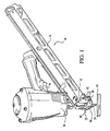
- FIG. 1 is a perspective view of the POSITIVE PLACEMENT® tool of the present invention;
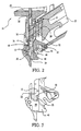
- FIG. 2 is a cross sectional view of the nosepiece and shear block assembly and the magazine of the tool of FIG. 1 with short nails loaded;
- FIG. 3 is a cross sectional view of the assembly of FIG. 2 with long nails loaded;
- FIG. 4 is a detail of a side elevation of the nosepiece windows with the nail strip shown in phantom;
- FIG. 5 is a detail side view of the nosepice and shear block assembly having the workpiece contact element and the cap disengaged from a plurality of bosses;
- FIG. 6 is a side view of the assembly of FIG. 5 having the cap engaged with a plurality of bosses;
- FIG. 7 is a side view of the assembly of FIG. 5 with the shear block separated from the nosepiece; and
- FIG. 8 is a bottom view of the assembly of FIG. 5.
- Referring to FIGs. 1-3, a power tool, generally designated 10, is shown with a nosepiece and
shear block assembly 12 having a driver blade. Thetool 10 is commonly used for driving afastener 14 into aworkpiece 16, such as in a nailing or framing operation. Thefastener 14 is generally loaded into amagazine 18 that is removably attached to thetool 10. Thefastener 14 is contemplated as being any type of fastener that is satisfactorily driven into theworkpiece 16, such as nails, brads, staples, tacks and the like. To hold a plurality of thefasteners 14 in the same orientation and to handle many fasteners at once, the fasteners are generally attached to acollation tape 20, which is typically made of paper or plastic. The general appearance and the operational details ofsuch power tools 10 are very well known in the art. Directional references used herein are to be interpreted as if thetool 10 were oriented with anosepiece 22 approximately perpendicular to and in contact with theworkpiece 16, as shown in FIG. 1. - Referring to FIGs. 2 and 3, the
assembly 12 includes thenosepiece 22 that is configured for attachment to thetool 10. Atubular barrel 24 is formed at least partially by thenosepiece 22, and guides thefasteners 14 as they are driven into theworkpiece 16 by adriver blade 26. Thebarrel 24 extends from the resting position of thedriver blade 26 near abody 28 of thetool 10 to anexit 29 at the surface of theworkpiece 16 when thetool 10 is ready to drive thefastener 14. A rear-facingopening 30 in thebarrel 24 receives thefastener 14 from themagazine 18 oriented so that apenetrating portion 32 of thefastener 14 is closest to theworkpiece 16 and the length of the fastener is generally parallel with the barrel. When thetool 10 is in contact with theworkpiece 16 and a trigger 34 (FIG. 1) is activated by the user, thedriver blade 26 rapidly travels through thebarrel 24. At theopening 30, thedriver 26 contacts thefastener 14 and propels it through the remaining length of thebarrel 24 and into theworkpiece 16. - Optionally, the
nosepiece 22 has one ormore windows 36 extending to thebarrel 24 seen best in FIG. 4. Thewindows 36 are constructed and arranged to align with the path of thecollation tape 20. Anyshape window 36 is suitable, although a slot shape is preferred. If thecollation tape 20 does not tear off with theprevious fastener 14, it is aligned to protrude through thewindow 36, allowing thenext fastener 14 to completely enter thebarrel 24. Thecollation tape 20 is likely to be dispelled by subsequent shots of thetool 10. Occasionally, thecollation tape 20 will become folded, bent or otherwise misaligned so that it fails to align with thewindows 36, and begins to build-up in thebarrel 24. In this case, thewindows 36 permit the user to observe thepaper 20 build-up and remove thetape 20 before a jam occurs. Access to thebarrel 24 is provided to facilitate the clearance ofcollation tape 20 to jams. Any configuration known in the art for providing access to thebarrel 24 is useful with this invention. Onepreferable assembly 12 has thebarrel 24 formed partially by thenosepiece 22 and partially by an adjoiningshear block 40 that is configured to be secured to the nosepiece to complete the barrel. An advantage of forming thebarrel 24 so that thenosepiece 22 and theshear block 40 are adjacent to and separable from each other, as seen in FIG. 7, is that theassembly 12 is conveniently cleared of jams. - Referring now to FIGs. 2 and 3, the
assembly 12 includes a biased fastener-size adjustment device 42. Preferably, thedevice 42 is in the form of a rebound lever that is pivotally attached to theshear block 40 and is positioned such that the rebound lever pivots in response to the length of thefastener 14. Thefasteners 14 move from themagazine 18 into theopening 30 in thebarrel 24, oriented approximately vertically. The length of theopening 30 is at least as long as thelongest fastener 14 that is intended to be used intool 10. As thelong fasteners 14 move down themagazine 18 toward theopening 30, a penetratingend 32 of thefastener 14 contacts therebound lever 42. Therebound lever 42 is biased, as with a spring 45 (shown hidden) urging it upward as shown in FIG. 2, to press it against thefasteners 14. Thefasteners 14 push downwardly against therebound lever 42, pushing it out of the path of thefasteners 14. - One surface of the
rebound lever 42 is referred to as a blockingsurface 46 since it is to obscure unused portions of theopening 30. The blockingsurface 46 is adjacent to thebarrel 24 of thetool 10. As therebound lever 42 pivots up and down with respect to the length of thefasteners 14, the blockingsurface 46 changes the effective length of theopening 30 as therebound lever 42 pivots. The shape of the blockingsurface 46 is not critical, however, an arc shape is preferred. - Following the driving of a
fastener 14, as thedriver blade 26 retracts up the length of thebarrel 24 and moves upwardly past theopening 30, thenext fastener 14 is pushed into thebarrel 24 by the springloaded clip ormagazine 18. As thetool 10 is fired, thedriver blade 26 contacts thefastener 14 and begins to push it down thebarrel 24, it has a tendency to bounce or rebound off thewall 48 and begins to exit the barrel through theopening 30. When long nails 14 are loaded, the rebounding nail often hits the next nail in themagazine 18 and is reflected back into thebarrel 24. But whenshort nails 14 are used, they can rotate through theopening 30, partially exiting thebarrel 24 below the end of thenext fastener 14. The blocking of theopening 30 by the blockingsurface 46 between the bottom of thefastener 14 and the bottom of the opening keeps the fastener inside thebarrel 24 even if it rebounds. - When it is desired to change to
smaller nails 24, the improved nosepiece andshear block assembly 12 allows thetool 10 to adjust automatically to the different length fastener. Asshort fasteners 14 pass through themagazine 18, they do not cause therebound lever 42 to rotate as much as the long nails. Compared to thelong nails 14, the biasing force of thespring 45 is not overcome, and reboundlever 42 is not depressed as far by the short nails, so that more of the blockingsurface 46 adjoining thebarrel 24 closes off the unused portion of theopening 30. When theshort nail 14 rebounds off of thewall 48, it encounters the blockingsurface 46 instead of entering theshear block 40, and is deflected back into thebarrel 24. Reducing the effect of rebound is particularly advantageous on a POSITIVEPLACEMENT® tool 10 as tofastener 14 is urged along a straighter path through thebarrel 24, improving the accuracy of its placement. - When the clip or
magazine 18 is changed or refilled with an additional supply offasteners 14, therebound lever 42 automatically adjusts to the length of the newly loaded fasteners. Thefasteners 14 push therebound lever 42 sufficiently out of the way to allow them to pass by unimpeded, while the biasing force provided by thespring 45 pushes therebound lever 42 upward to contact the penetratingtip 32 of thefastener 14, closing the unused portion of theopening 30. Regardless of the length of thefastener 14, therebound lever 42 pivots to contact the penetratingtip 32. - Referring to FIG. 7, some
tools 10 of this type have a quick clearing feature whereby thenosepiece 22 easily separates from theshear block 40 by operation of a latch (not shown). This feature is used to quickly open thebarrel 24 of thetool 10 to clear a jam and close the barrel again without having multiple parts to disassemble. Such features are well known in the art. Forces in play during firing tend to push against thebarrel 24 walls, trying to push apart thenosepiece 22 andshear block 40. Where thenosepiece 22 and theshear block 40 are separable, stress is placed on the latch mechanism or other apparatus normally holding thenosepiece 22 andshear block 40 together. If the latch is worn after a great deal of use, it could possibly disengage during firing, allowing thenosepiece 22 and theshear block 40 to fly apart. - The possibility of latch failure is minimized by incorporating at least one
boss 52 on theshear block 40 that matingly engages a raisedcap 54 on amovable element 56, such as a workpiece contact element. When in its lower or resting position, as shown in FIG. 5, theworkpiece contact element 56 interlocks with the firing mechanism (not shown) to assure that thetool 10 does not fire unless in contact with theworkpiece 16. In this position, the nosepiece and shear block are separable, allowing the user to clear a jam if needed. As theworkpiece contact element 56 is pushed upward, in a motion parallel to the length of thebarrel 24 to a firing position shown in FIG. 6, theworkpiece contact element 56 engages theshear block 40 as described in more detail below. This position allows thetool 10 to fire but prohibits separation of thenosepiece 22 andshear block 40. Theworkpiece contact element 56 is preferably spring biased to automatically return to its resting position when thetool 10 is lifted from the surface of theworkpiece 16. After firing of thetool 10, the firing mechanism is locked out until activated again by engagement of theworkpiece contact element 56. - The raised
cap 54 is designed to easily move over theboss 52 in a direction that is parallel to thebarrel 24, but to prevent movement that would allow separation of thenosepiece 22 from theshear block 40. As shown in FIG. 8, theboss 52 has a cross section that is generally semi-circular, but other cross sectional shapes, such as triangles, rectangles and the like are also suitable. When theworkpiece contact element 56 moves upward in response to placement of thetool 10 on theworkpiece 16, thecap 54 slides over theboss 52 as seen in FIG. 6. FIG. 7 shows disengagement of thetool 10 from theworkpiece 16 that also disengages thecap 54 from theboss 52, allowing quick separation of the nosepiece andshear block assembly 12. Thus, thenosepiece 22 and theshear block 40 cannot accidentally separate during firing of thetool 10 and a jam can be cleared only when thetool 10 is disabled from firing. - Still referring to FIGs. 5, 6 and 7, the
shear block 40 optionally has one or more of thebosses 52 also referred to as first bosses, and thenosepiece 22 has one or moresecond bosses 60. Although the use ofmultiple caps 54 is contemplated, an economical embodiment uses a single cap to engagemultiple bosses bosses cap 54 of theworkpiece contact element 56 when it is engaged with theworkpiece 16. The use of additional devices to further secure thecap 54 and thebosses bosses 60 on thenosepiece 22 and at least oneboss 52 on theshear block 40, shown in FIGs. 1, 5, 7 and 8.
Claims (6)
- A nosepiece and shear block assembly (12) for a fastening tool that drives a fastener (14) supplied from a plurality of fasteners, comprising:- a nosepiece (22) being configured for attachment to the tool;- a shear block (40) configured to be secured to said nosepiece (22) and having a first boss (52); and- said nosepiece (22) having a workpiece contact element (56) slidingly attached to said nosepiece and having at least one cap (54), said cap being configured to engage said first boss when said workpiece contact element engages a workpiece (16).
- The assembly of claim 1, further comprising at least one second boss (60) on said nosepiece.
- The assembly of claim 1, wherein said first boss (52) and second boss (60) are arranged linearly and coaxially.
- The assembly of claim 1, wherein said cap (54) engages both said first boss (52) and said second boss (60).
- The assembly of claim 1, wherein:- said nosepiece (22) further defines a portion of a barrel (24);- said shear block (40) is further configured to complete said barrel (24);- said barrel further comprising an opening (30) for receiving the fastener (14); and- said assembly including a biased fastener-size adjustment device (42) which exerts a biasing force against fasteners adjacent said opening.
- A power tool for driving a fastener into a workpiece comprising:- a fastener supply (18) removably engaged with said tool for providing a fastener from a plurality of fasteners; and- a nosepiece and shear block assembly according to one of claims 1 to 5.
Applications Claiming Priority (2)
| Application Number | Priority Date | Filing Date | Title |
|---|---|---|---|
| US10/155,456 US6808101B2 (en) | 2002-05-24 | 2002-05-24 | Framing tool with automatic fastener-size adjustment |
| EP03291237A EP1364750B1 (en) | 2002-05-24 | 2003-05-23 | Nosepiece and shear block assembly for a fastening tool and said fastening tool |
Related Parent Applications (1)
| Application Number | Title | Priority Date | Filing Date |
|---|---|---|---|
| EP03291237A Division EP1364750B1 (en) | 2002-05-24 | 2003-05-23 | Nosepiece and shear block assembly for a fastening tool and said fastening tool |
Publications (2)
| Publication Number | Publication Date |
|---|---|
| EP1832390A1 true EP1832390A1 (en) | 2007-09-12 |
| EP1832390B1 EP1832390B1 (en) | 2008-12-10 |
Family
ID=29400579
Family Applications (2)
| Application Number | Title | Priority Date | Filing Date |
|---|---|---|---|
| EP07290685A Expired - Lifetime EP1832390B1 (en) | 2002-05-24 | 2003-05-23 | Nosepiece and shear block assembly for a fastening tool and said fastening tool |
| EP03291237A Expired - Lifetime EP1364750B1 (en) | 2002-05-24 | 2003-05-23 | Nosepiece and shear block assembly for a fastening tool and said fastening tool |
Family Applications After (1)
| Application Number | Title | Priority Date | Filing Date |
|---|---|---|---|
| EP03291237A Expired - Lifetime EP1364750B1 (en) | 2002-05-24 | 2003-05-23 | Nosepiece and shear block assembly for a fastening tool and said fastening tool |
Country Status (12)
| Country | Link |
|---|---|
| US (1) | US6808101B2 (en) |
| EP (2) | EP1832390B1 (en) |
| JP (1) | JP4316927B2 (en) |
| AT (2) | ATE389513T1 (en) |
| AU (1) | AU2003204262B2 (en) |
| CA (1) | CA2422447C (en) |
| DE (2) | DE60319767T2 (en) |
| DK (2) | DK1364750T3 (en) |
| ES (2) | ES2301764T3 (en) |
| MX (1) | MXPA03004558A (en) |
| NZ (3) | NZ526029A (en) |
| PT (2) | PT1832390E (en) |
Cited By (2)
| Publication number | Priority date | Publication date | Assignee | Title |
|---|---|---|---|---|
| EP2165806A3 (en) * | 2008-09-23 | 2011-03-09 | Robert Bosch GmbH | Nail gun with integrated safety device |
| US10814465B2 (en) | 2016-03-22 | 2020-10-27 | Stanley Black & Decker, Inc. | Safety device for tackers |
Families Citing this family (63)
| Publication number | Priority date | Publication date | Assignee | Title |
|---|---|---|---|---|
| WO2003031124A1 (en) * | 2001-10-03 | 2003-04-17 | Max Kabushiki Kaisha | Fastener magazine of fastening machine |
| JP4214833B2 (en) * | 2003-05-09 | 2009-01-28 | マックス株式会社 | Nail driving guide mechanism in nailing machine |
| USD551931S1 (en) * | 2003-11-19 | 2007-10-02 | Black & Decker Inc. | Pneumatic fastener |
| USD498127S1 (en) * | 2003-11-19 | 2004-11-09 | Porter-Cable Corporation | Pneumatic fastener |
| US20050127130A1 (en) * | 2003-12-11 | 2005-06-16 | Jan Toczycki | Frame tool and fastener |
| US20050189396A1 (en) * | 2004-02-24 | 2005-09-01 | Leasure Jeremy D. | Pneumatic fastener |
| US7988025B2 (en) * | 2004-02-24 | 2011-08-02 | Black & Decker Inc. | Pneumatic fastener |
| JP4420205B2 (en) * | 2004-04-28 | 2010-02-24 | マックス株式会社 | Nail guide device for nailing machine |
| US7703649B2 (en) * | 2004-05-04 | 2010-04-27 | Illinois Tool Works, Inc. | Collations for fasteners of various lengths |
| US7971768B2 (en) * | 2004-05-04 | 2011-07-05 | Illinois Tool Works Inc. | Guidance system for fasteners |
| USD514911S1 (en) * | 2005-01-11 | 2006-02-14 | Eastway Fair Company Limited | Angled finish nailer |
| USD531475S1 (en) * | 2005-07-08 | 2006-11-07 | Xiaopeng Li | Air nail gun |
| USD560108S1 (en) * | 2005-07-19 | 2008-01-22 | Milwaukee Electric Tool Corporation | Power tool, such as a nailer |
| USD540136S1 (en) * | 2006-01-11 | 2007-04-10 | Stanley Fastening Systems, L.P. | Fastening tool |
| TWI286966B (en) * | 2006-01-17 | 2007-09-21 | Basso Ind Corp | Structure against malposition for nail case |
| JP5055775B2 (en) * | 2006-02-03 | 2012-10-24 | マックス株式会社 | Nailer |
| JP4400587B2 (en) * | 2006-03-16 | 2010-01-20 | 日立工機株式会社 | Driving machine |
| US7240818B1 (en) * | 2006-05-05 | 2007-07-10 | Apach Industrial Co., Ltd. | Adjustable device for adjusting space for nails in magazine of nail gun |
| USD556003S1 (en) * | 2006-05-26 | 2007-11-27 | Black & Decker Inc. | Nailer |
| USD562664S1 (en) * | 2006-05-26 | 2008-02-26 | Black & Decker Inc. | Nailer |
| USD554963S1 (en) * | 2006-06-22 | 2007-11-13 | Illinois Tool Works Inc. | Fastener driving tool housing |
| US7318545B1 (en) * | 2006-07-12 | 2008-01-15 | Chung-Heng Lee | Stapler with a staple-supporting device |
| US7617957B2 (en) * | 2006-08-14 | 2009-11-17 | Illinois Tool Works Inc. | Mounting system for the exhaust gas deflector of a power tool |
| US7506789B2 (en) * | 2006-08-28 | 2009-03-24 | Arrow Fastener Company, Inc. | Continuous feed cap system |
| US20080067212A1 (en) * | 2006-09-14 | 2008-03-20 | Wan-Fu Wen | Magazine for Nail Gun |
| US8684245B2 (en) * | 2006-10-20 | 2014-04-01 | Stanley Fastening Systems, L.P. | Fastener driving device with mechanisms to limit movement of nails |
| USD575127S1 (en) * | 2007-06-08 | 2008-08-19 | Black & Decker Inc. | Fastening tool |
| USD575607S1 (en) * | 2007-06-11 | 2008-08-26 | Black & Decker Inc. | Fastening tool |
| US8931676B2 (en) * | 2007-08-27 | 2015-01-13 | Black & Decker Inc. | Nailer having mechanism for pre-positioning nail |
| FR2920332B1 (en) * | 2007-09-05 | 2010-04-23 | Spit Soc Prospect Inv Techn | FIXING TOOL FOR FIXING ELEMENTS OF DIFFERENT LENGTHS |
| US8123096B2 (en) * | 2007-09-13 | 2012-02-28 | Hitachi Koki Co., Ltd. | Driving machine |
| JP5348456B2 (en) * | 2007-09-13 | 2013-11-20 | 日立工機株式会社 | Driving machine |
| FR2931380B1 (en) * | 2008-05-26 | 2010-08-20 | Prospection Et D Inventsions T | FLEXIBLE FIXING TOOL WITH FLEXIBLE BLADE |
| US10442065B2 (en) * | 2011-05-23 | 2019-10-15 | Illinois Tool Works Inc. | Stud miss indicator for fastener driving tool |
| ITBO20110303A1 (en) * | 2011-05-25 | 2012-11-26 | Fasco Srl | LOADER DEVICE FOR NAILER AND SIMILAR |
| JP2013111719A (en) * | 2011-11-30 | 2013-06-10 | Makita Corp | Driving tool |
| US10391619B2 (en) * | 2012-06-18 | 2019-08-27 | Quick Grip Staples (Hk) Limited | Accessory for a fastening gun |
| EP3401060B1 (en) * | 2013-08-30 | 2019-10-23 | Illinois Tool Works, Inc. | Staple tool |
| US9796072B2 (en) | 2013-08-30 | 2017-10-24 | Illinois Tool Works Inc. | Staple tool |
| US9527196B2 (en) | 2013-11-06 | 2016-12-27 | Illinois Tool Works Inc. | Fastener driving tool with an automatic nose chamber guide member |
| JP6524650B2 (en) * | 2014-11-28 | 2019-06-05 | 工機ホールディングス株式会社 | Driving machine |
| TWM517078U (en) * | 2015-10-02 | 2016-02-11 | 鑽全實業股份有限公司 | Nail gun with protective structure |
| US10350741B2 (en) * | 2015-11-02 | 2019-07-16 | Black & Decker Inc. | Powered nail driver with a nail placement assembly |
| US10668608B2 (en) | 2016-02-10 | 2020-06-02 | Illinois Tool Works Inc. | Fastener driving tool |
| USD787290S1 (en) | 2016-02-10 | 2017-05-23 | Illinois Tool Works Inc. | Pneumatic nailer |
| US20180093370A1 (en) * | 2016-10-04 | 2018-04-05 | Stanley Black & Decker, Inc. | Fastening Tool with Contact Arm and Multi-Fastener Guide |
| JP7271438B2 (en) | 2017-05-03 | 2023-05-11 | シグノード インダストリアル グループ リミティド ライアビリティ カンパニー | electric stapling device |
| EP4721926A2 (en) * | 2017-05-05 | 2026-04-08 | Illinois Tool Works Inc. | Combination fastening tool |
| USD854820S1 (en) | 2017-11-14 | 2019-07-30 | Illinois Tool Works Inc. | Fastener driving tool belt hook |
| USD855431S1 (en) | 2017-11-14 | 2019-08-06 | Illinois Tool Works Inc. | Fastener driving tool pipe hook |
| US10926391B2 (en) | 2017-11-14 | 2021-02-23 | Illinois Tool Works Inc. | Powered fastener driving tool having hook assemblies |
| US10576616B2 (en) | 2018-05-07 | 2020-03-03 | Black & Decker Inc. | Power tool wire form hook assembly |
| US10766127B2 (en) | 2018-05-07 | 2020-09-08 | Black & Decker Inc. | Nosepiece assembly with a passage for ejecting debris |
| US11433521B2 (en) | 2019-03-13 | 2022-09-06 | Milwaukee Electric Tool Corporation | Powered fastener driver |
| US10987791B2 (en) * | 2019-04-01 | 2021-04-27 | Testo Industry Corp. | Probe assembly of a metal connector nailer |
| USD976093S1 (en) | 2020-09-22 | 2023-01-24 | Milwaukee Electric Tool Corporation | Staple collation |
| US11746815B2 (en) | 2020-09-22 | 2023-09-05 | Milwaukee Electric Tool Corporation | Staple and staple collation |
| US12162125B2 (en) | 2020-10-30 | 2024-12-10 | Milwaukee Electric Tool Corporation | Powered fastener driver |
| WO2022113643A1 (en) * | 2020-11-26 | 2022-06-02 | 工機ホールディングス株式会社 | Work machine |
| CN113858126B (en) * | 2021-11-08 | 2025-03-28 | 浙江荣鹏气动工具股份有限公司 | A nail gun nail head front anti-air striking device |
| EP4482651A1 (en) * | 2022-02-21 | 2025-01-01 | Kyocera Senco Industrial Tools, Inc. | Magazine fastener guide for a fastener driving tool |
| US12521855B2 (en) | 2023-04-14 | 2026-01-13 | Illinois Tool Works Inc. | Fastener driving tool having a retractable probe assembly |
| US20240375257A1 (en) * | 2023-05-12 | 2024-11-14 | Illinois Tool Works Inc. | Apparatus for driving fasteners |
Citations (5)
| Publication number | Priority date | Publication date | Assignee | Title |
|---|---|---|---|---|
| US3491932A (en) * | 1967-04-21 | 1970-01-27 | Fastener Corp | Fastener driving tool |
| US4597517A (en) * | 1985-06-21 | 1986-07-01 | Signode Corporation | Magazine interlock for a fastener driving device |
| US5297713A (en) * | 1993-03-31 | 1994-03-29 | Stanley-Bostitch, Inc. | Rear load magazine assembly |
| US5437404A (en) * | 1993-07-13 | 1995-08-01 | Illinois Tool Works Inc. | Adjustable shear block assembly |
| WO2001010603A2 (en) * | 1999-08-06 | 2001-02-15 | Stanley Fastening Systems, Lp | Fastener driving device with enhanced magazine latch assembly |
Family Cites Families (13)
| Publication number | Priority date | Publication date | Assignee | Title |
|---|---|---|---|---|
| DE2211511A1 (en) | 1972-03-10 | 1973-09-20 | Dieter Haubold Ind Nagelgeraet | MAGAZINE STRIP FOR A DEVICE FOR DRIVING DECORATIVE NAILS |
| US3834602A (en) * | 1973-01-26 | 1974-09-10 | Fastener Corp | Fastener driving tool |
| DE2750562C2 (en) | 1977-11-11 | 1983-04-21 | Signode Corp., Glenview, Ill. | Nails and tools for driving the nails combined into a nail strip |
| US4815647A (en) * | 1986-11-10 | 1989-03-28 | Chou Joseph S Y | Multiple-function magazine for tee nails to be used with a nailing gun |
| US4858812A (en) | 1988-06-28 | 1989-08-22 | Stanley-Bostitch, Inc. | Nail driving device with improved nail feeding mechanism |
| US5096109A (en) | 1991-01-02 | 1992-03-17 | Bex Nailing Machine Co., Ltd. | Fastener driving device with improved feeding mechanism |
| JPH04365567A (en) * | 1991-06-12 | 1992-12-17 | Makita Corp | Pusher device for nail driver |
| US5238167A (en) | 1992-10-09 | 1993-08-24 | Illinois Tool Works Inc. | Positioning mechanism for powered fastener-driving tool |
| US5335800A (en) * | 1993-07-06 | 1994-08-09 | Liu Chung Ho | Magazine for rivet gun |
| US5452835A (en) | 1994-08-01 | 1995-09-26 | Illinois Tool Works Inc. | Positioning mechanism for powered fastener-driving tool |
| JP3520754B2 (en) | 1997-12-19 | 2004-04-19 | 日立工機株式会社 | Driving machine |
| US6053389A (en) * | 1998-08-05 | 2000-04-25 | Sup Drogon Enterprise Co., Ltd. | Nailing gun magazine specially designed for big nail set |
| US6279808B1 (en) | 1999-07-27 | 2001-08-28 | Mark E. Larsen | Nail guide mechanism for a nail gun |
-
2002
- 2002-05-24 US US10/155,456 patent/US6808101B2/en not_active Expired - Lifetime
-
2003
- 2003-03-18 CA CA002422447A patent/CA2422447C/en not_active Expired - Lifetime
- 2003-05-20 AU AU2003204262A patent/AU2003204262B2/en not_active Expired
- 2003-05-21 NZ NZ526029A patent/NZ526029A/en not_active IP Right Cessation
- 2003-05-21 NZ NZ534181A patent/NZ534181A/en not_active IP Right Cessation
- 2003-05-21 NZ NZ535346A patent/NZ535346A/en not_active IP Right Cessation
- 2003-05-22 MX MXPA03004558A patent/MXPA03004558A/en active IP Right Grant
- 2003-05-23 EP EP07290685A patent/EP1832390B1/en not_active Expired - Lifetime
- 2003-05-23 ES ES03291237T patent/ES2301764T3/en not_active Expired - Lifetime
- 2003-05-23 JP JP2003146300A patent/JP4316927B2/en not_active Expired - Fee Related
- 2003-05-23 DE DE60319767T patent/DE60319767T2/en not_active Expired - Lifetime
- 2003-05-23 DK DK03291237T patent/DK1364750T3/en active
- 2003-05-23 PT PT07290685T patent/PT1832390E/en unknown
- 2003-05-23 AT AT03291237T patent/ATE389513T1/en not_active IP Right Cessation
- 2003-05-23 PT PT03291237T patent/PT1364750E/en unknown
- 2003-05-23 ES ES07290685T patent/ES2318838T3/en not_active Expired - Lifetime
- 2003-05-23 DE DE60325289T patent/DE60325289D1/en not_active Expired - Fee Related
- 2003-05-23 AT AT07290685T patent/ATE416886T1/en not_active IP Right Cessation
- 2003-05-23 EP EP03291237A patent/EP1364750B1/en not_active Expired - Lifetime
- 2003-05-23 DK DK07290685T patent/DK1832390T3/en active
Patent Citations (5)
| Publication number | Priority date | Publication date | Assignee | Title |
|---|---|---|---|---|
| US3491932A (en) * | 1967-04-21 | 1970-01-27 | Fastener Corp | Fastener driving tool |
| US4597517A (en) * | 1985-06-21 | 1986-07-01 | Signode Corporation | Magazine interlock for a fastener driving device |
| US5297713A (en) * | 1993-03-31 | 1994-03-29 | Stanley-Bostitch, Inc. | Rear load magazine assembly |
| US5437404A (en) * | 1993-07-13 | 1995-08-01 | Illinois Tool Works Inc. | Adjustable shear block assembly |
| WO2001010603A2 (en) * | 1999-08-06 | 2001-02-15 | Stanley Fastening Systems, Lp | Fastener driving device with enhanced magazine latch assembly |
Cited By (2)
| Publication number | Priority date | Publication date | Assignee | Title |
|---|---|---|---|---|
| EP2165806A3 (en) * | 2008-09-23 | 2011-03-09 | Robert Bosch GmbH | Nail gun with integrated safety device |
| US10814465B2 (en) | 2016-03-22 | 2020-10-27 | Stanley Black & Decker, Inc. | Safety device for tackers |
Also Published As
| Publication number | Publication date |
|---|---|
| NZ535346A (en) | 2005-12-23 |
| JP4316927B2 (en) | 2009-08-19 |
| EP1364750A3 (en) | 2004-06-23 |
| MXPA03004558A (en) | 2003-11-27 |
| DE60319767T2 (en) | 2009-04-23 |
| ATE389513T1 (en) | 2008-04-15 |
| EP1832390B1 (en) | 2008-12-10 |
| NZ526029A (en) | 2004-08-27 |
| PT1832390E (en) | 2009-02-20 |
| EP1364750B1 (en) | 2008-03-19 |
| JP2003340746A (en) | 2003-12-02 |
| DE60325289D1 (en) | 2009-01-22 |
| ATE416886T1 (en) | 2008-12-15 |
| CA2422447C (en) | 2008-05-20 |
| AU2003204262B2 (en) | 2006-02-02 |
| AU2003204262A1 (en) | 2003-12-11 |
| NZ534181A (en) | 2006-01-27 |
| US6808101B2 (en) | 2004-10-26 |
| ES2318838T3 (en) | 2009-05-01 |
| US20030218044A1 (en) | 2003-11-27 |
| EP1364750A2 (en) | 2003-11-26 |
| DK1832390T3 (en) | 2009-04-06 |
| ES2301764T3 (en) | 2008-07-01 |
| CA2422447A1 (en) | 2003-11-24 |
| DE60319767D1 (en) | 2008-04-30 |
| PT1364750E (en) | 2008-06-02 |
| DK1364750T3 (en) | 2008-06-23 |
Similar Documents
| Publication | Publication Date | Title |
|---|---|---|
| EP1832390B1 (en) | Nosepiece and shear block assembly for a fastening tool and said fastening tool | |
| EP1813394B1 (en) | Combustion chamber control for combustion-powered fastener-driving tool | |
| AU2016206349B2 (en) | Fastener feeder delay for fastener driving tool | |
| US8336748B2 (en) | Fastener driver with driver assembly blocking member | |
| AU2003204769B2 (en) | Trim-type fastener driving tool | |
| EP1053834B1 (en) | Combustion powered tool with combustion chamber delay | |
| EP4153382B1 (en) | Dry-fire lockout and last fastener retention mechanism for powered fastener driver | |
| US6708860B1 (en) | Setting tool for fastening elements | |
| US7383974B2 (en) | Combustion chamber control for combustion-powered fastener-driving tool | |
| CA2694967C (en) | Actuator pin guide for a fastener driving tool | |
| KR20070114275A (en) | Power nailer with driver blade blocking mechanism in the magazine | |
| US4565312A (en) | Powder actuated tool with safety | |
| US20220274236A1 (en) | Slap hammer with cap dispenser | |
| US8146788B2 (en) | Fastening tool with releasable work contact element | |
| JP7795644B2 (en) | Magazine fastener guide for fastener driving tools |
Legal Events
| Date | Code | Title | Description |
|---|---|---|---|
| PUAI | Public reference made under article 153(3) epc to a published international application that has entered the european phase |
Free format text: ORIGINAL CODE: 0009012 |
|
| AC | Divisional application: reference to earlier application |
Ref document number: 1364750 Country of ref document: EP Kind code of ref document: P |
|
| AK | Designated contracting states |
Kind code of ref document: A1 Designated state(s): AT BE BG CH CY CZ DE DK EE ES FI FR GB GR HU IE IT LI LU MC NL PT RO SE SI SK TR |
|
| AX | Request for extension of the european patent |
Extension state: AL LT LV MK |
|
| 17P | Request for examination filed |
Effective date: 20071004 |
|
| 17Q | First examination report despatched |
Effective date: 20071220 |
|
| AKX | Designation fees paid |
Designated state(s): AT BE BG CH CY CZ DE DK EE ES FI FR GB GR HU IE IT LI LU MC NL PT RO SE SI SK TR |
|
| GRAP | Despatch of communication of intention to grant a patent |
Free format text: ORIGINAL CODE: EPIDOSNIGR1 |
|
| GRAS | Grant fee paid |
Free format text: ORIGINAL CODE: EPIDOSNIGR3 |
|
| GRAS | Grant fee paid |
Free format text: ORIGINAL CODE: EPIDOSNIGR3 |
|
| GRAA | (expected) grant |
Free format text: ORIGINAL CODE: 0009210 |
|
| AC | Divisional application: reference to earlier application |
Ref document number: 1364750 Country of ref document: EP Kind code of ref document: P |
|
| AK | Designated contracting states |
Kind code of ref document: B1 Designated state(s): AT BE BG CH CY CZ DE DK EE ES FI FR GB GR HU IE IT LI LU MC NL PT RO SE SI SK TR |
|
| REG | Reference to a national code |
Ref country code: GB Ref legal event code: FG4D |
|
| REG | Reference to a national code |
Ref country code: CH Ref legal event code: EP |
|
| REG | Reference to a national code |
Ref country code: IE Ref legal event code: FG4D |
|
| REF | Corresponds to: |
Ref document number: 60325289 Country of ref document: DE Date of ref document: 20090122 Kind code of ref document: P |
|
| REG | Reference to a national code |
Ref country code: PT Ref legal event code: SC4A Free format text: AVAILABILITY OF NATIONAL TRANSLATION Effective date: 20090213 |
|
| REG | Reference to a national code |
Ref country code: DK Ref legal event code: T3 |
|
| REG | Reference to a national code |
Ref country code: ES Ref legal event code: FG2A Ref document number: 2318838 Country of ref document: ES Kind code of ref document: T3 |
|
| PG25 | Lapsed in a contracting state [announced via postgrant information from national office to epo] |
Ref country code: SI Free format text: LAPSE BECAUSE OF FAILURE TO SUBMIT A TRANSLATION OF THE DESCRIPTION OR TO PAY THE FEE WITHIN THE PRESCRIBED TIME-LIMIT Effective date: 20081210 Ref country code: FI Free format text: LAPSE BECAUSE OF FAILURE TO SUBMIT A TRANSLATION OF THE DESCRIPTION OR TO PAY THE FEE WITHIN THE PRESCRIBED TIME-LIMIT Effective date: 20081210 |
|
| PG25 | Lapsed in a contracting state [announced via postgrant information from national office to epo] |
Ref country code: BG Free format text: LAPSE BECAUSE OF FAILURE TO SUBMIT A TRANSLATION OF THE DESCRIPTION OR TO PAY THE FEE WITHIN THE PRESCRIBED TIME-LIMIT Effective date: 20090310 Ref country code: RO Free format text: LAPSE BECAUSE OF FAILURE TO SUBMIT A TRANSLATION OF THE DESCRIPTION OR TO PAY THE FEE WITHIN THE PRESCRIBED TIME-LIMIT Effective date: 20081210 Ref country code: EE Free format text: LAPSE BECAUSE OF FAILURE TO SUBMIT A TRANSLATION OF THE DESCRIPTION OR TO PAY THE FEE WITHIN THE PRESCRIBED TIME-LIMIT Effective date: 20081210 |
|
| PGFP | Annual fee paid to national office [announced via postgrant information from national office to epo] |
Ref country code: DK Payment date: 20090528 Year of fee payment: 7 Ref country code: ES Payment date: 20090526 Year of fee payment: 7 Ref country code: NL Payment date: 20090524 Year of fee payment: 7 |
|
| PG25 | Lapsed in a contracting state [announced via postgrant information from national office to epo] |
Ref country code: CZ Free format text: LAPSE BECAUSE OF FAILURE TO SUBMIT A TRANSLATION OF THE DESCRIPTION OR TO PAY THE FEE WITHIN THE PRESCRIBED TIME-LIMIT Effective date: 20081210 Ref country code: SE Free format text: LAPSE BECAUSE OF FAILURE TO SUBMIT A TRANSLATION OF THE DESCRIPTION OR TO PAY THE FEE WITHIN THE PRESCRIBED TIME-LIMIT Effective date: 20090310 Ref country code: AT Free format text: LAPSE BECAUSE OF FAILURE TO SUBMIT A TRANSLATION OF THE DESCRIPTION OR TO PAY THE FEE WITHIN THE PRESCRIBED TIME-LIMIT Effective date: 20081210 |
|
| PGFP | Annual fee paid to national office [announced via postgrant information from national office to epo] |
Ref country code: DE Payment date: 20090528 Year of fee payment: 7 Ref country code: IT Payment date: 20090526 Year of fee payment: 7 Ref country code: PT Payment date: 20090512 Year of fee payment: 7 |
|
| PG25 | Lapsed in a contracting state [announced via postgrant information from national office to epo] |
Ref country code: SK Free format text: LAPSE BECAUSE OF FAILURE TO SUBMIT A TRANSLATION OF THE DESCRIPTION OR TO PAY THE FEE WITHIN THE PRESCRIBED TIME-LIMIT Effective date: 20081210 |
|
| PGFP | Annual fee paid to national office [announced via postgrant information from national office to epo] |
Ref country code: BE Payment date: 20090624 Year of fee payment: 7 |
|
| PLBE | No opposition filed within time limit |
Free format text: ORIGINAL CODE: 0009261 |
|
| STAA | Information on the status of an ep patent application or granted ep patent |
Free format text: STATUS: NO OPPOSITION FILED WITHIN TIME LIMIT |
|
| 26N | No opposition filed |
Effective date: 20090911 |
|
| PGFP | Annual fee paid to national office [announced via postgrant information from national office to epo] |
Ref country code: GB Payment date: 20090528 Year of fee payment: 7 |
|
| PG25 | Lapsed in a contracting state [announced via postgrant information from national office to epo] |
Ref country code: MC Free format text: LAPSE BECAUSE OF NON-PAYMENT OF DUE FEES Effective date: 20090531 |
|
| REG | Reference to a national code |
Ref country code: CH Ref legal event code: PL |
|
| PG25 | Lapsed in a contracting state [announced via postgrant information from national office to epo] |
Ref country code: CH Free format text: LAPSE BECAUSE OF NON-PAYMENT OF DUE FEES Effective date: 20090531 Ref country code: LI Free format text: LAPSE BECAUSE OF NON-PAYMENT OF DUE FEES Effective date: 20090531 |
|
| REG | Reference to a national code |
Ref country code: FR Ref legal event code: ST Effective date: 20100129 |
|
| REG | Reference to a national code |
Ref country code: IE Ref legal event code: MM4A |
|
| PG25 | Lapsed in a contracting state [announced via postgrant information from national office to epo] |
Ref country code: FR Free format text: LAPSE BECAUSE OF NON-PAYMENT OF DUE FEES Effective date: 20090602 Ref country code: IE Free format text: LAPSE BECAUSE OF NON-PAYMENT OF DUE FEES Effective date: 20090523 |
|
| PG25 | Lapsed in a contracting state [announced via postgrant information from national office to epo] |
Ref country code: GR Free format text: LAPSE BECAUSE OF FAILURE TO SUBMIT A TRANSLATION OF THE DESCRIPTION OR TO PAY THE FEE WITHIN THE PRESCRIBED TIME-LIMIT Effective date: 20090311 |
|
| BERE | Be: lapsed |
Owner name: ILLINOIS TOOL WORKS INC. Effective date: 20100531 |
|
| REG | Reference to a national code |
Ref country code: PT Ref legal event code: MM4A Free format text: LAPSE DUE TO NON-PAYMENT OF FEES Effective date: 20101123 |
|
| REG | Reference to a national code |
Ref country code: NL Ref legal event code: V1 Effective date: 20101201 |
|
| REG | Reference to a national code |
Ref country code: DK Ref legal event code: EBP |
|
| GBPC | Gb: european patent ceased through non-payment of renewal fee |
Effective date: 20100523 |
|
| PG25 | Lapsed in a contracting state [announced via postgrant information from national office to epo] |
Ref country code: PT Free format text: LAPSE BECAUSE OF NON-PAYMENT OF DUE FEES Effective date: 20101123 |
|
| PG25 | Lapsed in a contracting state [announced via postgrant information from national office to epo] |
Ref country code: NL Free format text: LAPSE BECAUSE OF NON-PAYMENT OF DUE FEES Effective date: 20101201 Ref country code: BE Free format text: LAPSE BECAUSE OF NON-PAYMENT OF DUE FEES Effective date: 20100531 Ref country code: IT Free format text: LAPSE BECAUSE OF NON-PAYMENT OF DUE FEES Effective date: 20100523 |
|
| PG25 | Lapsed in a contracting state [announced via postgrant information from national office to epo] |
Ref country code: DK Free format text: LAPSE BECAUSE OF NON-PAYMENT OF DUE FEES Effective date: 20100531 Ref country code: DE Free format text: LAPSE BECAUSE OF NON-PAYMENT OF DUE FEES Effective date: 20101201 Ref country code: LU Free format text: LAPSE BECAUSE OF NON-PAYMENT OF DUE FEES Effective date: 20090523 |
|
| PG25 | Lapsed in a contracting state [announced via postgrant information from national office to epo] |
Ref country code: HU Free format text: LAPSE BECAUSE OF FAILURE TO SUBMIT A TRANSLATION OF THE DESCRIPTION OR TO PAY THE FEE WITHIN THE PRESCRIBED TIME-LIMIT Effective date: 20090611 |
|
| REG | Reference to a national code |
Ref country code: ES Ref legal event code: FD2A Effective date: 20110708 |
|
| PG25 | Lapsed in a contracting state [announced via postgrant information from national office to epo] |
Ref country code: ES Free format text: LAPSE BECAUSE OF NON-PAYMENT OF DUE FEES Effective date: 20110628 Ref country code: GB Free format text: LAPSE BECAUSE OF NON-PAYMENT OF DUE FEES Effective date: 20100523 |
|
| PG25 | Lapsed in a contracting state [announced via postgrant information from national office to epo] |
Ref country code: TR Free format text: LAPSE BECAUSE OF FAILURE TO SUBMIT A TRANSLATION OF THE DESCRIPTION OR TO PAY THE FEE WITHIN THE PRESCRIBED TIME-LIMIT Effective date: 20081210 |
|
| PG25 | Lapsed in a contracting state [announced via postgrant information from national office to epo] |
Ref country code: CY Free format text: LAPSE BECAUSE OF FAILURE TO SUBMIT A TRANSLATION OF THE DESCRIPTION OR TO PAY THE FEE WITHIN THE PRESCRIBED TIME-LIMIT Effective date: 20081210 Ref country code: ES Free format text: LAPSE BECAUSE OF NON-PAYMENT OF DUE FEES Effective date: 20100524 |