EP1832381A1 - Surface Processing - Google Patents
Surface Processing Download PDFInfo
- Publication number
- EP1832381A1 EP1832381A1 EP07103389A EP07103389A EP1832381A1 EP 1832381 A1 EP1832381 A1 EP 1832381A1 EP 07103389 A EP07103389 A EP 07103389A EP 07103389 A EP07103389 A EP 07103389A EP 1832381 A1 EP1832381 A1 EP 1832381A1
- Authority
- EP
- European Patent Office
- Prior art keywords
- internal diameter
- surface section
- thermally sprayed
- sprayed coating
- rough surface
- Prior art date
- Legal status (The legal status is an assumption and is not a legal conclusion. Google has not performed a legal analysis and makes no representation as to the accuracy of the status listed.)
- Granted
Links
Images




Classifications
-
- C—CHEMISTRY; METALLURGY
- C23—COATING METALLIC MATERIAL; COATING MATERIAL WITH METALLIC MATERIAL; CHEMICAL SURFACE TREATMENT; DIFFUSION TREATMENT OF METALLIC MATERIAL; COATING BY VACUUM EVAPORATION, BY SPUTTERING, BY ION IMPLANTATION OR BY CHEMICAL VAPOUR DEPOSITION, IN GENERAL; INHIBITING CORROSION OF METALLIC MATERIAL OR INCRUSTATION IN GENERAL
- C23C—COATING METALLIC MATERIAL; COATING MATERIAL WITH METALLIC MATERIAL; SURFACE TREATMENT OF METALLIC MATERIAL BY DIFFUSION INTO THE SURFACE, BY CHEMICAL CONVERSION OR SUBSTITUTION; COATING BY VACUUM EVAPORATION, BY SPUTTERING, BY ION IMPLANTATION OR BY CHEMICAL VAPOUR DEPOSITION, IN GENERAL
- C23C4/00—Coating by spraying the coating material in the molten state, e.g. by flame, plasma or electric discharge
- C23C4/02—Pretreatment of the material to be coated, e.g. for coating on selected surface areas
-
- B—PERFORMING OPERATIONS; TRANSPORTING
- B23—MACHINE TOOLS; METAL-WORKING NOT OTHERWISE PROVIDED FOR
- B23P—METAL-WORKING NOT OTHERWISE PROVIDED FOR; COMBINED OPERATIONS; UNIVERSAL MACHINE TOOLS
- B23P9/00—Treating or finishing surfaces mechanically, with or without calibrating, primarily to resist wear or impact, e.g. smoothing or roughening turbine blades or bearings; Features of such surfaces not otherwise provided for, their treatment being unspecified
- B23P9/02—Treating or finishing by applying pressure, e.g. knurling
-
- C—CHEMISTRY; METALLURGY
- C23—COATING METALLIC MATERIAL; COATING MATERIAL WITH METALLIC MATERIAL; CHEMICAL SURFACE TREATMENT; DIFFUSION TREATMENT OF METALLIC MATERIAL; COATING BY VACUUM EVAPORATION, BY SPUTTERING, BY ION IMPLANTATION OR BY CHEMICAL VAPOUR DEPOSITION, IN GENERAL; INHIBITING CORROSION OF METALLIC MATERIAL OR INCRUSTATION IN GENERAL
- C23C—COATING METALLIC MATERIAL; COATING MATERIAL WITH METALLIC MATERIAL; SURFACE TREATMENT OF METALLIC MATERIAL BY DIFFUSION INTO THE SURFACE, BY CHEMICAL CONVERSION OR SUBSTITUTION; COATING BY VACUUM EVAPORATION, BY SPUTTERING, BY ION IMPLANTATION OR BY CHEMICAL VAPOUR DEPOSITION, IN GENERAL
- C23C4/00—Coating by spraying the coating material in the molten state, e.g. by flame, plasma or electric discharge
- C23C4/12—Coating by spraying the coating material in the molten state, e.g. by flame, plasma or electric discharge characterised by the method of spraying
-
- F—MECHANICAL ENGINEERING; LIGHTING; HEATING; WEAPONS; BLASTING
- F16—ENGINEERING ELEMENTS AND UNITS; GENERAL MEASURES FOR PRODUCING AND MAINTAINING EFFECTIVE FUNCTIONING OF MACHINES OR INSTALLATIONS; THERMAL INSULATION IN GENERAL
- F16J—PISTONS; CYLINDERS; SEALINGS
- F16J10/00—Engine or like cylinders; Features of hollow, e.g. cylindrical, bodies in general
- F16J10/02—Cylinders designed to receive moving pistons or plungers
- F16J10/04—Running faces; Liners
-
- Y—GENERAL TAGGING OF NEW TECHNOLOGICAL DEVELOPMENTS; GENERAL TAGGING OF CROSS-SECTIONAL TECHNOLOGIES SPANNING OVER SEVERAL SECTIONS OF THE IPC; TECHNICAL SUBJECTS COVERED BY FORMER USPC CROSS-REFERENCE ART COLLECTIONS [XRACs] AND DIGESTS
- Y10—TECHNICAL SUBJECTS COVERED BY FORMER USPC
- Y10T—TECHNICAL SUBJECTS COVERED BY FORMER US CLASSIFICATION
- Y10T29/00—Metal working
- Y10T29/49—Method of mechanical manufacture
- Y10T29/49229—Prime mover or fluid pump making
- Y10T29/4927—Cylinder, cylinder head or engine valve sleeve making
- Y10T29/49272—Cylinder, cylinder head or engine valve sleeve making with liner, coating, or sleeve
-
- Y—GENERAL TAGGING OF NEW TECHNOLOGICAL DEVELOPMENTS; GENERAL TAGGING OF CROSS-SECTIONAL TECHNOLOGIES SPANNING OVER SEVERAL SECTIONS OF THE IPC; TECHNICAL SUBJECTS COVERED BY FORMER USPC CROSS-REFERENCE ART COLLECTIONS [XRACs] AND DIGESTS
- Y10—TECHNICAL SUBJECTS COVERED BY FORMER USPC
- Y10T—TECHNICAL SUBJECTS COVERED BY FORMER US CLASSIFICATION
- Y10T428/00—Stock material or miscellaneous articles
- Y10T428/24—Structurally defined web or sheet [e.g., overall dimension, etc.]
- Y10T428/24273—Structurally defined web or sheet [e.g., overall dimension, etc.] including aperture
-
- Y—GENERAL TAGGING OF NEW TECHNOLOGICAL DEVELOPMENTS; GENERAL TAGGING OF CROSS-SECTIONAL TECHNOLOGIES SPANNING OVER SEVERAL SECTIONS OF THE IPC; TECHNICAL SUBJECTS COVERED BY FORMER USPC CROSS-REFERENCE ART COLLECTIONS [XRACs] AND DIGESTS
- Y10—TECHNICAL SUBJECTS COVERED BY FORMER USPC
- Y10T—TECHNICAL SUBJECTS COVERED BY FORMER US CLASSIFICATION
- Y10T428/00—Stock material or miscellaneous articles
- Y10T428/24—Structurally defined web or sheet [e.g., overall dimension, etc.]
- Y10T428/24355—Continuous and nonuniform or irregular surface on layer or component [e.g., roofing, etc.]
-
- Y—GENERAL TAGGING OF NEW TECHNOLOGICAL DEVELOPMENTS; GENERAL TAGGING OF CROSS-SECTIONAL TECHNOLOGIES SPANNING OVER SEVERAL SECTIONS OF THE IPC; TECHNICAL SUBJECTS COVERED BY FORMER USPC CROSS-REFERENCE ART COLLECTIONS [XRACs] AND DIGESTS
- Y10—TECHNICAL SUBJECTS COVERED BY FORMER USPC
- Y10T—TECHNICAL SUBJECTS COVERED BY FORMER US CLASSIFICATION
- Y10T428/00—Stock material or miscellaneous articles
- Y10T428/24—Structurally defined web or sheet [e.g., overall dimension, etc.]
- Y10T428/24355—Continuous and nonuniform or irregular surface on layer or component [e.g., roofing, etc.]
- Y10T428/24372—Particulate matter
Definitions
- the present invention generally relates to surface processing and particularly, but not exclusively, to a surface processing method for applying a thermally sprayed coating to a member having a cylindrical internal surface that has been formed into a rough surface. Aspects of the invention also relate to an apparatus and a base member having a cylindrical internal surface.
- aluminum engine blocks of internal combustion engines have cylinder liners provided in their cylinder bores. From the viewpoint of improving the output, fuel economy, and exhaust performance of internal combustion engines having aluminum cylinder blocks and from the viewpoint of reducing the size and weight of such engines, there is a very high demand for an engine design that eliminates the cylinder liners that are used in the cylinder bores of aluminum engine blocks.
- One alternative to cylinder liners is to use thermal spraying technology to form a thermally sprayed coating on the internal surfaces of the cylinder bores.
- a coating is formed on the internal surface of the cylinder bore using a thermal spray gun configured to spray molten coating material.
- the coating is deposited by moving the thermal spray gun in the axial direction inside the cylinder bore while rotating the thermal spray gun. After the thermally sprayed coating is formed, the surface of the coating is finished by grinding using a honing process or other machining process.
- the internal surface of the base material of the cylinder bore is roughened using, for example, the surface treatment proposed in Japanese Laid-Open Patent Publication No. 2003-213399 (see Figures 2 to 7).
- the surface roughening serves to improve the adhesion of the thermally sprayed coating.
- the internal surface of the internal cylindrical bore is roughened before the thermally sprayed coating is deposited in order to improve the adhesion of the thermally sprayed coating, the internal diameter of the internal cylindrical bore cannot be measured accurately and there are times when the thermally sprayed coating cannot be made to the proper thickness.
- Embodiments of the invention may enable an internal diameter of an internal cylindrical bore to be measured accurately before a thermally sprayed coating is deposited thereon.
- a base member comprising an internal cylindrical bore including a rough surface section and an internal diameter measurement surface section provided on an axial end of the internal cylindrical bore, the internal diameter measurement surface section being smoother than the rough surface section and a thermally sprayed coating formed on the rough surface section of the internal cylindrical bore.
- the internal diameter measurement surface section is processed using a tool that is used to form the rough surface section.
- the rough surface section and the internal diameter measuring surface section are formed by cutting with the tool while the tool is both rotated and moved axially with an axial feed speed of the tool being slower when processing the internal diameter measurement surface section than when processing the rough surface section.
- the internal diameter measurement surface section has an internal diameter that is identical to a maximum internal diameter of the rough surface section as defined by a bottom of a recess of the rough surface section.
- a cylindrical internal surface processing method comprising providing a base member having an internal cylindrical bore, forming a rough surface section along an internal surface of the internal cylindrical bore, forming an internal diameter measurement surface section on an axial end of the internal cylindrical bore, with the internal diameter measurement surface section being smoother than the rough surface section and forming a thermally sprayed coating onto the rough surface section of the internal surface of the internal cylindrical bore after forming the internal diameter measurement surface section.
- the forming of the internal diameter measurement surface section is performed using a tool that is used in the forming of the rough surface section of the internal cylindrical bore.
- the forming of the rough surface section and the forming of the internal diameter measuring surface section are performed by cutting with the tool while both rotating and moved axially moving the tool, with an axial feed speed of the tool being slower when processing the internal diameter measurement surface section than when processing the rough surface section.
- the forming of the internal diameter measurement surface section is performed such that an internal diameter of the internal cylindrical bore at the internal diameter measurement surface section is made identical to a maximum internal diameter of the rough surface section as defined by a bottom of a recess of the rough surface section.
- the method may comprise measuring an internal diameter of the internal diameter measurement surface section to obtain a measurement result of the internal diameter of the internal diameter measurement surface section and determining an acceptability of the measurement result of the internal diameter of the internal diameter measurement surface section, and then performing the forming of the thermally sprayed coating onto the rough surface section of the internal surface of the internal cylindrical bore only if the measurement result is determined to be acceptable.
- the determining of the acceptability of the measurement result of the internal diameter of the internal diameter measurement surface section is based on a prescribed threshold value.
- the determining of the acceptability of the measurement result of the internal diameter of the internal diameter measurement surface section is determined to be acceptable when an internal diameter measurement value of the measurement result is equal to or smaller than a first prescribed threshold value and larger than a second prescribed threshold value such that a honing process can be performed entirely on the thermally sprayed coating along the rough surface section without at least a portion of the base member being exposed by the honing process of the thermally sprayed coating after the thermally sprayed coating is formed.
- the method may comprise measuring an internal diameter of the internal diameter measurement surface section to obtain a measurement result of the internal diameter of the internal diameter measurement surface section and adjusting a spray condition used in performing the forming of the thermally sprayed coating onto the rough surface section based on the measurement result of the internal diameter of the internal diameter measurement surface section.
- the forming of the thermally sprayed coating onto the rough surface section is performed by using a thermal spray gun configured to spray a molten coating material with the thermal spray gun moving reciprocally inside the internal cylindrical bore while rotating the thermal spray gun and the spray condition to be adjusted includes a number of times the thermal spray gun is moved reciprocally inside the internal cylindrical bore.
- the adjusting of the spray condition includes increasing the number of times the thermal spray gun is moved reciprocally as the measurement result of the internal diameter of the internal diameter measurement surface section becomes larger.
- the method may comprise removing the internal diameter measurement surface section together with the thermally sprayed coating in a vicinity of the internal diameter measurement surface section after the thermally sprayed coating is formed.
- a cylindrical internal surface processing apparatus comprising an internal diameter measuring device configured to measure an internal diameter of an internal cylindrical bore formed in a base member to obtain a measurement result of the internal diameter and a quality determining section configured to determine if the internal diameter measurement result obtained by the internal diameter measuring device is acceptable to allow a subsequent thermally sprayed coating to be applied.
- the quality determining section is further configured to determine an acceptability of the measurement result of the internal diameter measurement surface section is based on a prescribed threshold value.
- the quality determining section is configured to determine that the measurement result of the internal diameter measurement is acceptable when an internal diameter measurement value is equal to or smaller than a first prescribed threshold value and larger than a second prescribed threshold value such that a honing process can be performed entirely on the thermally sprayed coating along the rough surface section without at least a portion of the base member being exposed by the honing process of the thermally sprayed coating after the thermally sprayed coating is formed.
- a base member may comprise an internal cylindrical bore and a thermally sprayed coating.
- the internal cylindrical bore includes a rough surface section and an internal diameter measurement surface section provided on an axial end of the internal cylindrical bore.
- the internal diameter measurement surface section is smoother than the rough surface section.
- the thermally sprayed coating is formed on the rough surface section of the internal cylindrical bore.
- a cylinder block is illustrated as a base member in accordance with a first embodiment of the present invention.
- the cylinder block 1 has a cylinder bore 3 that is an internal cylindrical bore with an internal cylindrical surface 5.
- a thermally sprayed coating 7 is formed on the cylinder bore internal surface 5 using a method that is described later (see diagram (d) of Figure 3). After the thermally sprayed coating 7 is formed, it is finished using a finishing method described later (honing in this embodiment).
- Figure 1 shows the internal cylindrical surface 5 after it has been made into a rough surface 13 and before the thermally sprayed coating 7 has been deposited.
- Figure 2 shows the internal diameter of the internal cylindrical surface 5 being measured with an internal diameter measuring instrument 9 that constitutes an internal diameter measuring device or section.
- Figure 2 is an enlarged cross sectional view of the end portion of the cylinder block 1 located axially closer to the crankcase 11.
- the rough surface 13 extends axially from the upper end of the internal cylindrical surface 5 to a position near the bottom end.
- the rough surface 13 has a helical (screw-shaped) recessed cut portion 15 and a ridge portion 16 with a finely serrated portion 17 that is also helical.
- the serrated portion 17 is arranged adjacent to the recessed cut portion 15.
- An internal diameter measurement surface 19 that is smoother than the rough surface 13 is formed on a portion of the internal cylindrical surface 5 immediately below the rough surface 13.
- the internal cylindrical surface 5 has rough surface section A where the rough surface 13 is formed and an internal diameter measurement section B where the internal diameter measurement surface 19 is formed.
- the internal diameter of the cylinder bore 3 at the internal diameter measurement surface 19 is the same as the internal diameter of the cylinder bore 3 at the deepest portion 15a (bottom) of the cut portion 15.
- An escape section 21 having a larger diameter than the internal diameter measurement surface 19 is provided below the internal diameter measurement surface 19.
- the internal diameter of the cylinder bore 3 is measured at the internal diameter measurement surface 19 with the internal diameter measuring instrument 9 when the rough surface 13 has been formed on the internal cylindrical surface 5 and the smooth internal diameter measurement surface 19 has been formed directly below the rough surface 13.
- the internal diameter measuring instrument 9 includes a rod 9a, a horizontal arm 9b, a probe 9c and a roller 9d.
- the rod 9a extends in the vertical direction in Figure 2.
- the horizontal arm 9b is attached to the bottom end of the rod 9a.
- the measuring probe 9c is provided on a front end of the horizontal arm 9b.
- the roller 9d is provided on a rear end of the horizontal arm 9b.
- the measuring probe 9c is capable of extending and retracting with respect to the horizontal arm 9b.
- the roller 9d is put into contact with the internal diameter measurement surface 19 and the measuring probe 9c is put into contact with the internal diameter measurement surface 19 at a position opposite the position where the roller 9d is contacting.
- an acceptability determination is made as to whether or not the measurement result is acceptable (i.e., good or bad) and the processing proceeds to a subsequent thermally sprayed coating forming step only if the result is acceptable (i.e., "Good”). If the result is unacceptable (i.e., "Bad"), then the thermally sprayed coating forming step is aborted.
- the internal diameter measuring surface 19 is smoother than the rough surface 13
- the internal diameter of the cylinder bore 3 can be measured accurately and easily before the thermally sprayed coating 7 is formed and the thermally sprayed coating 7 can be made to the proper thickness in a uniform manner.
- Figure 2 shows a case in which the internal diameter is measured manually with an internal diameter measuring instrument 9, it is also acceptable to measure the internal diameter automatically with a three-dimensional measuring instrument.
- Figure 3 shows the left-hand portion of the view of the cylinder bore 3 shown in Figure 2 and illustrates the processing steps applied to the cylinder bore 3.
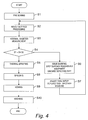
- Figure 4 is a flowchart showing the order of the processing steps illustrated in Figure 3. The processing steps will now be explained with reference to Figures 3 and 4.
- Diagram (a) of Figure 3 shows the state of the cylinder block 1 after casting.
- the cylinder bore 3 has a tapered section 23 configured to decrease in diameter as one moves downward (i.e., downward from the perspective of Figure 3) toward the crankcase 11.
- Diagram (b) of Figure 3 shows the cylinder bore 3 after the tapered section 23 shown in diagram (a) of Figure 3 has been subjected to a fine boring process with a boring device (not shown) (step S1).
- the fine boring is performed to create a uniform diameter section 25 having a uniform internal diameter.
- the uniform diameter section 25 spans the entire length of the tapered section 23, except for a lower end section thereof.
- the boring device comprises a boring bar with a tool arranged around the outside perimeter of a tip end thereof. The fine boring is accomplished by rotating the boring bar while inserting the boring bar into the cylinder bore 3 from above.
- the boring device After forming the uniform diameter section 25, the boring device forms a downwardly widening tapered section 27 directly below the uniform diameter section 25 (at the lower end of the cylinder bore 3) and the escape section 21 shown in Figure 2 directly below the tapered section 27.
- the tapered section 27 and the escape section 21, which have larger diameters than the uniform diameter section 25, are formed by rotating the boring bar eccentrically with respect to the main axis of the boring device.
- the base material surface roughening process is performed as shown in Figure 5 using a boring device similar to that used for the boring processing shown in diagram (b) of Figure 3.
- a tool (bit) 30 is mounted to the outer perimeter of the tip end of the boring bar 29 of the boring device.
- the boring bar 29 is simultaneously rotated and moved axially downward so as to form a screw thread along the internal cylindrical surface 5.
- the resulting rough surface of the base material has the helical recessed cut portion 15 and the finely serrated portion 17 arranged helically adjacent to the cut portion 15.
- Figure 6A shows the cut portion 15 and the ridge portion 16 with the finely serrated portion 17 being formed in the uniform diameter section 25 of the cylinder bore 3 with the tool 30 so as to create the rough surface 13.
- Figure 6B shows a reference example illustrating a normal screw thread being cut with a tool 201.
- the tool 201 is rotated and moved downward simultaneously and the cut waste material 203 is discharged in the direction of the arrow A.
- a valley portion 205 (a bottom of a recess) and a ridge portion 207 are formed with a normal screw thread cutting process.
- the tool 30 shown in Figure 6A is configured such that the angle ⁇ 1 of the surface 30a (the side facing in the opposite direction as the feed direction of the tool, i.e. upward) with respect to a horizontal plane H is approximately 30 degrees, which is larger than the corresponding angle ⁇ 2 of the tool 201 shown in Figure 6B. Meanwhile, the angle ⁇ 1 of the surface 30b (the side facing in the same direction as the feed direction of the tool, i.e. downward) with respect to the horizontal plane 30 is approximately 10 degrees, which is smaller than the corresponding angle ⁇ 2 of the tool 201 shown in Figure 6B.
- the internal diameter measurement surface 19 shown in Figure 2 is formed in the tapered section 27.
- the internal diameter measurement surface 19 is formed using the boring bar 29 and the tool 30 shown in Figure 5, but the tool feed speed is slower than the tool feed speed used when processing the rough surface 13.
- the internal diameter measurement section B having the internal diameter measurement surface 19 is formed immediately below the rough surface section A where the rough surface 13 is formed.
- the feed speed of the tool 30 in the axial direction of the cylinder bore 3 is changed at a boundary P between the sections A and B. By reducing the tool feed speed when processing the internal diameter measurement section B located below the boundary P, the internal diameter measurement surface 19 is processed to be smoother than the rough surface 13.
- the manufacturing process can be contrived such that processing of the internal diameter measurement surface 19 proceeds directly after processing of the rough surface 13 in a continuous fashion, thus enabling the processing time to be reduced and the processing efficiency to be improved.
- the internal diameter of the cylinder bore 3 at the internal diameter measurement surface 19 is the same as the internal diameter of the cylinder bore 3 at the deepest portion 15a of the cut portion 15. Also internal diameter of the cylinder bore 3 at the internal diameter measurement surface 19 is smaller than the internal diameter of the escape section 21. A portion 27a of the tapered surface 27 shown in diagram (b) of Figure 3 remains between the internal diameter measurement surface 19 and the escape section 21.
- the manufacturing process can be performed such that it continues directly from processing of the rough surface 13 to processing of the internal diameter measurement surface 19 by merely reducing the tool feed speed. As a result, the processing can be executed efficiency.
- the internal diameter D is measured with the internal diameter measuring instrument 9 shown in Figure 2 (step S3).
- Figure 7 is a block diagram showing the control configuration of a controller that compares the measured internal diameter D to a prescribed lower limit threshold value D1 and a prescribed upper limit threshold value D2 to determine if the internal diameter D is acceptable (i.e., good or bad).
- the control configuration of the controller includes an internal diameter measuring control section 96, a quality determining circuit or section 97, a warning display device or section 98 and a surface roughening control section 99.
- the internal diameter measuring control section 96 receives the measurement results from the internal diameter measuring instrument 9.
- the quality determining circuit 97 serves as a quality determining device that is provided with a memory (storage device) in which the prescribed lower limit threshold value D1 and the prescribed upper limit threshold value D2 are stored.
- the quality determining circuit or section 97 sends a signal for displaying the warning to the warning display device or section 98.
- the warning display device 98 includes a monitor or the like.
- the surface roughening control section 99 controls the operation of the surface roughening equipment, e.g., the boring bar 29, the tool 30 and the honing device 105.
- the lower and upper limit threshold values D1 and D2 are set to obtain a range for a final target internal diameter to be obtained by honing the thermally sprayed coating. If the internal diameter of the base material along the rough surface 13 is too small, then the base material along the rough surface 13 will be exposed, i.e., all of the coating will be removed, before the desired final diameter can be achieved with the honing process. On the other hand, if the internal diameter of the base material along the rough surface 13 is too large, the base material along the rough surface 13, then not all of the coating on the base material along the rough surface 13 will be processed, i.e., not all of the coating will be honed, when the desired final diameter has been achieved with the honing process.
- the lower limit threshold value D1 corresponds to an internal diameter with which at least a portion of the base material along the rough surface 13 will become exposed when the surface of the thermally sprayed coating shown in diagram (f) of Figure 3 is honed with a specific honing tool, i.e., the honing tool 105 shown in Figure 9 (described later). More specifically, the base material will not become exposed when the thermally sprayed coating is honed if the internal diameter measurement value D is larger than the lower limit threshold value D1. Conversely, at least a portion of the base material will become exposed due to too much removal of the thermally sprayed coating during honing if the internal diameter threshold value D is equal to or smaller than the lower limit threshold value D1.
- the upper limit threshold value D2 corresponds to an internal diameter with which is possible to process the entire surface of the thermally sprayed coating that is to be processed when the thermally sprayed coating shown in diagram (f) of Figure 3 is honed with a specific honing tool, i.e., the honing tool 105 shown in Figure 9.
- the upper limit threshold value D2 is a value for which there will be no portion of the thermally sprayed coating left unprocessed after the honing is completed. More specifically, the entire surface of the thermally sprayed coating to be processed can be processed (honed) if the internal diameter measurement value D is equal to or smaller than the upper limit threshold value D2.
- the threshold values D1 and D2 are determined based on the error (variation) of the honing process and the error (variation) of the thickness distribution of the thermally sprayed coating in the axial and circumferential directions (actually the error of the internal diameter at a particular position on the surface of the thermally sprayed coating, i.e., portion of the internal cylindrical bore where the coating is formed).
- the error (variation) of the coating thickness in the axial direction is chiefly in the form of the cylinder bore 3 being tapered along the axial direction, and the error (variation) of the coating thickness in the circumferential direction is chiefly in the form of the cylinder bore 3 being oval instead of circular.
- the quality determining circuit 97 acquires the internal diameter measurement value D and determines if the internal diameter measurement value D is larger than the lower limit threshold value D1 and equal to or smaller than the upper limit threshold value D2 (step S4).
- step S4 If the internal diameter measurement value D is larger than the lower limit threshold value D1 and equal to or smaller than the upper limit threshold value D2 (i.e., if the result of step S4 is Yes), then the radially outward facing surfaces of the honing stones 109 (which face the surface of the thermally sprayed coating) are within the range of the coating thickness in the thickness direction and the honing process will not cause the base material to become exposed by removing too much of the thermally sprayed coating or the like. Furthermore, the radially outward facing surfaces of the honing stones 109 will contact the entire surface of the thermally sprayed coating and there will not be any portions left unprocessed (untouched) by the honing stones 109. In short, the measurement result is determined to be acceptable and a signal is sent to the surface roughening control section 99 shown in Figure 7 so as to continue to a subsequent thermally sprayed coating formation step (step S5).
- step S4 if the internal diameter measurement value D is equal to or smaller than the lower limit threshold value D1 or larger than the upper limit threshold value D2 (i.e., if the result of step S4 is "No"), then, as described previously, at least a portion of the base material will become exposed due to too much removal of the thermally sprayed coating during honing or there will be a portion or portions of the surface of the thermally sprayed coating that remain unprocessed (untouched) by the honing stones 109. In other words, the honing process will fail if it is attempted. Consequently, the internal cylindrical bore is considered to be defective and the measurement result is unacceptable (i.e., "Bad"). A signal for displaying a warning is sent to the warning display device 98, the operation of the surface roughening control section 99 is stopped, and the defective part is discarded (step S6).
- the cause of the defective (bad) part is investigated and corrected (step S7). If the internal diameter measurement value D is equal to or smaller than the lower limit threshold value D1, then there is the possibility that the setup (mounting condition) of the tool 30 shown in Figure 5 is incorrect or that the tool 30 is chipped or worn. To correct the problem, the setup of the tool 30 is adjusted or the tool 30 is replaced with a new tool 30. If the internal diameter measurement value D is larger than the upper threshold value D2, then there is the possibility that the setup of the tool 30 is incorrect or that a built-up edge has developed on the tip of the tool 30. To correct the problem, the setup of the tool 30 is adjusted, the tool 30 is replaced with a new tool 30, or the built-up edge is removed.
- the surface roughening control section 99 is restarted and surface roughening processing is resumed on either the existing base member (e.g., the cylinder block 1), if still useable, or a new base member (e.g., the cylinder block 1).
- the thermally sprayed coating formation step S5 corresponds to diagram (d) of Figure 3.
- the thermally sprayed coating 7 formed in this step covers the entire rough surface 13 and a portion of the internal diameter measurement surface 19.
- the thermally sprayed coating 7 is formed such that thickness of the coating 7 is substantially uniform across the rough surface 13.
- the internal diameter measurement value D when the internal diameter measurement value D is larger, the number of times the thermal spray gun 31 used to form the coating 7 is moved reciprocally is increased in order to make the coating 7 thicker. Conversely, when the internal diameter measurement value D is smaller, the number of times the thermal spray gun 31 used to form the coating 7 is moved reciprocally is decreased in order to make the coating 7 thinner. As a result, the internal diameter of the cylinder bore 3 can be brought close to a specified value after the thermally sprayed coating 7 is formed.
- FIG 8 is a schematic view showing the entire thermal spraying apparatus used to form the thermally sprayed coating 7 onto the internal cylindrical surface 5 of the cylinder block 1 after the internal cylindrical surface 5 has been roughened as shown in diagram (c) of Figure 3.
- This thermal spraying apparatus includes a gas-fueled wire-melting type thermal spray gun configured to be inserted into the center of the cylinder bore 3.
- a ferrous metal wire material 37 used as the thermal spray coating material is melted and discharged from a thermal spray opening 31a in the form of molten droplets 33.
- the molten droplets 33 are deposited onto the internal surface 5 of the cylinder bore 3 so as to form a thermally sprayed coating 7.
- the thermal spray gun 31 is configured to receive the ferrous metal wire material 37 fed from a wire material feeding device 35, fuel (e.g., acetylene, propane, or ethylene gas) fed from a fuel gas storage tank 39 through a pipe 43, and oxygen from an oxygen storage tank 41 through a pipe 45.
- fuel e.g., acetylene, propane, or ethylene gas
- oxygen from an oxygen storage tank 41 through a pipe 45.
- the wire material 37 is fed downward into the thermal spray gun 31 via a wire material feed hole 47 that is formed so as to pass vertically through a center portion of the thermal spray gun 31.
- the fuel and oxygen are fed into a gas guide passage 51 that passes vertically through a cylindrical portion 49 disposed around the outside of the wire material feed hole 47.
- the mixture of the fuel and oxygen flows out from a lower opening 51 a (lower from the perspective of Figure 8) of the gas guide passage 51 and is ignited so as to form a combustion flame 53.
- An atomizing air passage 55 is provided on a more outer portion of the cylindrical portion 49 and an accelerator air passage 61 is formed still farther to the outside between a cylindrical partitioning wall 57 and a cylindrical outer wall 59.
- the atomizing air passage 55 flowing through the atomizing air passage 55 serves to push the heat of the combustion flame 53 forward (downward in Figure 8) while cooling the surrounding portions of the gun 31. It also serves to blow the molten wire material 37 forward. Meanwhile, the accelerator air flowing through the accelerator air passage 61 serves to blow the molten wire material 37 in a direction crosswise to the direction in which the wire material 37 has been blown by the atomizing air. As a result, droplets 33 of molten wire material 37 are blown toward the internal cylindrical surface 5 and form a thermally sprayed coating 7 on the internal cylindrical surface 5.
- the atomizing air is supplied to the atomizing air passage 55 from an atomizing air supply source 67 through an air supply pipe 71 provided with a pressure reducing valve 69.
- the accelerator air is supplied to the accelerator air passage 61 from an accelerator air supply source 73 through an air supply pipe 79 provided with a pressure reducing valve 75 and a micro-mist filter 77.
- the partitioning wall 57 between the atomizing air passage 55 and the accelerator air passage 61 is provided with a rotary cylinder part 83 configured such that it can rotate with respect to the outer wall 59 on a bearing 81.
- the rotary cylinder part 83 is disposed on a lower end portion of the partitioning wall 57 in Figure 8.
- Rotary vanes 85 are provided on an upper outside portion of the rotary cylinder part 83 so as to be positioned in the accelerator air passage 61.
- the accelerator air flowing through the accelerator air passage 61 acts against the rotary vanes 85 and causes the rotary cylinder part 83 to rotate.
- a tip member 87 is fixed to the tip end (bottom end) face 83a of the rotary cylinder part 83 such that it rotates integrally with the rotary cylinder part 83.
- a protruding portion 91 having a discharge passage 89 passing there-through is provided on a portion of the periphery of the tip member 87.
- the discharge passage communicates with the accelerator air passage 61 through the bearing 81.
- the aforementioned thermal spray opening 31 a for discharging the molten droplets 33 is provided at the tip end of the discharge passage 89.
- the tip member 87 provided with the thermal spray opening 31a is rotated integrally with the rotary cylinder part 83 while the thermal spray gun 31 is moved reciprocally along the axial direction of the cylinder bore 3. In this way, substantially the entire internal surface 5 of the cylinder bore 3 can be coated with a thermally sprayed coating 7.
- the thickness of the thermally sprayed coating 7 is adjusted in accordance with the internal diameter measurement value D acquired by the quality determining circuit 97 by appropriately setting the number of times the thermal spray gun 31 moves reciprocally in the axial direction of the cylinder bore 3. More specifically, when the internal diameter measurement value D is larger, the number of times the thermal spray gun 31 is moved reciprocally is increased in order to make the coating 7 thicker. Conversely, when the internal diameter measurement value D is smaller, the number of times the thermal spray gun 31 is moved reciprocally is decreased in order to make the coating 7 thinner. As a result, the internal diameter of the cylinder bore 3 can be brought close to a specified value after the thermally sprayed coating 7 is formed.
- thermal spray coating material the wire material 37 shown in Figure 8
- the amount of coating material and other thermal spray conditions used to form the thermally sprayed coating 7 can be changed based on the measurement result.
- the number of times the thermal spray gun 31 is moved reciprocally in the axial direction and other thermal spray conditions are changed between steps S4 and S5 of the flowchart shown in Figure 4.
- the amount of coating material used to form the thermally sprayed coating 7 at a specified thickness of the coating 7 can be held to the minimum amount necessary and the material cost associated with the thermal spray process can be minimized. Also, formation of the thermally sprayed coating can be prevented when the internal diameter measurement value D is equal to or smaller than the lower limit threshold value D1 or larger than the upper limit threshold value D2, thereby avoiding waste of the coating material.
- a lower portion of the cylinder bore 3 that includes the internal diameter measurement surface 19 is machined by grinding as shown in diagram (e) of Figure 3.
- an upper end portion of the cylinder bore 3 is also machined (step S8). This grinding of the upper and lower ends of the cylinder bore 3 is accomplished using the same kind of boring apparatus as that shown in Figure 5, which is used for the rough surface forming processing shown in diagram (c) of Figure 3.
- the lower end portion of the cylinder bore 3 that is ground includes the internal diameter measurement surface 19, an adjacent portion of the rough surface 13 immediately above the internal diameter measurement surface 19, the portion of the thermally sprayed coating 7 located on the adjacent portion of the rough surface 13, and the escape section 21 located below the internal diameter measurement surface 19.
- the internal diameter measurement surface 19 is removed along with a portion of the thermally sprayed coating 7 in the vicinity of the internal diameter measurement surface 19.
- the lower end section is ground such that a cylindrical surface 93 is formed at the bottommost portion of the cylinder bore 3 and a tapered surface 95 configured such that its diameter narrows in the upward direction is formed above the cylindrical surface 93.
- the tapered surface 93 is formed across the entire thickness of the thermally sprayed coating 7 from the base material of the cylinder bore 3.
- the thermally sprayed coating 7 can be prevented from exfoliating due to stresses occurring in the poorly adhered portion during the subsequent honing process and the productivity of the cylinder block manufacturing process can be improved. Additionally, exfoliation of the thermally sprayed coating 7 resulting from the sliding resistance of a piston used in an internal combustion engine made with the cylinder block 1 can be prevented and the durability and reliability of the engine product can be improved.
- thermally sprayed coating 7 When the poorly adhered portions of the thermally sprayed coating 7 are removed, adjacent portions well-adhered thermally sprayed coating 7 are also removed. As a result, the thermally sprayed coating 7 that remains after the grinding process can reliably maintain a high degree of adhesion with respect to the base material.
- the poorly adhered portion of the thermally sprayed coating 7 can be removed reliably even if there is variance in the diameter and/or position of the ground portion from one cylinder bore 3 to the next.
- FIG. 9 is a cross sectional view of the cylinder block 1 showing the thermally sprayed coating 7 being honed with the honing tool 105.
- the honing tool 105 has the honing head 107 provided with, for example, four grindstones 109 containing grinding particles made of diamond or other material suitable for grinding.
- the grindstones 109 are arranged around the circumference of the honing head 107 with equal spacing therebetween in the circumferential direction.
- An expanding means configured to expand the grindstones 109 radially outward is provided inside the honing head 107. During the honing process, the expanding means presses the grindstones 109 against the internal surface 5 of the cylinder bore 3 with a prescribed pressure.
- the surface of the thermally sprayed coating 7 is ground, i.e., honed, by rotating the honing tool 105 while simultaneously moving it reciprocally in the axial direction.
- the honing process completes the processing of the internal cylindrical surface 5.
- the honing process can be contrived to comprise a succession of rough finishing and fine finishing steps executed using grindstones of different particle sizes (grain sizes).
- an air discharge opening for internal diameter measurement is provided on the external periphery of the honing head 107.
- air is discharged from the air discharge opening and the internal diameter is measured using an air micrometer configured and arranged to detect the discharge pressure of the air and convert it into an electric signal indicating the internal diameter.
- the honing process is ended when the measured internal diameter value reaches a prescribed value.
- the honing process is executed with respect to the thermally sprayed coating 7 only when the internal diameter measurement value D is larger than the lower limit threshold value D1 and equal to or smaller than the upper limit threshold value D2 (D1 ⁇ D ⁇ D2), i.e., when the result of the surface roughening process applied to the internal cylindrical surface 5 was good, the amount of honing required can be minimized and the amount of wear of the honing stones 109 can be minimized, thus contributing to reducing the manufacturing cost.
- step S10 the inside of the cylinder bore 3 is washed.
- the result of a measurement of the internal diameter at an internal diameter measurement surface 19 formed on the internal cylindrical surface 5 is determined to be acceptable (i.e., good or bad) based on the prescribed threshold values D1 and D2.
- a subsequent step of forming a thermally sprayed coating 7 on the internal cylindrical surface 5 is only executed if the measurement result is good.
- waste of the coating material can be avoided and the thickness of thermally sprayed coating 7 (at the surface position of the coating 7) can be managed appropriately such that situations in which a defective part (defective cylinder block) is discovered after the thermally sprayed coating 7 is formed can be prevented.
- Figure 10 shows the flow of processing steps from the base material surface roughening (pretreatment of base material before thermal spraying) and formation of the internal diameter measurement surface 19 shown in diagram (c) of Figure 3 to the honing processing shown in diagram (f) of Figure 3.
- a masking member (not shown in figures) is attached to the upper end portion of the cylinder block 1 and inside the crankcase 11 in order to prevent the coating material from adhering to portions where the coating is not required.
- the masking member is removed and the vicinity of the lower end section is ground (internal diameter measurement surface removal processing) as shown in diagram (e) of Figure 3. Finally, the coating is honed.
- the honing process is conducted by rotating the honing head 107 while moving it in the axial direction.
- the honing head 107 is moved upward while continuing to rotate it. This up and down reciprocal motion is executed repeatedly.
- the term “comprising” and its derivatives, as used herein, are intended to be open ended terms that specify the presence of the stated features, elements, components, groups, integers, and/or steps, but do not exclude the presence of other unstated features, elements, components, groups, integers and/or steps.
- the foregoing also applies to words having similar meanings such as the terms, “including”, “having” and their derivatives.
- the terms “part,” “section,” “portion,” “member” or “element” when used in the singular can have the dual meaning of a single part or a plurality of parts.
- the terms of degree such as “substantially”, “about” and “approximately” as used herein mean a reasonable amount of deviation of the modified term such that the end result is not significantly changed.
Landscapes
- Engineering & Computer Science (AREA)
- Chemical & Material Sciences (AREA)
- Mechanical Engineering (AREA)
- General Engineering & Computer Science (AREA)
- Plasma & Fusion (AREA)
- Physics & Mathematics (AREA)
- Chemical Kinetics & Catalysis (AREA)
- Materials Engineering (AREA)
- Metallurgy (AREA)
- Organic Chemistry (AREA)
- Combustion & Propulsion (AREA)
- Cylinder Crankcases Of Internal Combustion Engines (AREA)
- Coating By Spraying Or Casting (AREA)
Abstract
Description
- The present invention generally relates to surface processing and particularly, but not exclusively, to a surface processing method for applying a thermally sprayed coating to a member having a cylindrical internal surface that has been formed into a rough surface. Aspects of the invention also relate to an apparatus and a base member having a cylindrical internal surface.
- Typically, aluminum engine blocks of internal combustion engines have cylinder liners provided in their cylinder bores. From the viewpoint of improving the output, fuel economy, and exhaust performance of internal combustion engines having aluminum cylinder blocks and from the viewpoint of reducing the size and weight of such engines, there is a very high demand for an engine design that eliminates the cylinder liners that are used in the cylinder bores of aluminum engine blocks. One alternative to cylinder liners is to use thermal spraying technology to form a thermally sprayed coating on the internal surfaces of the cylinder bores.
- When thermal spraying technology is applied to a cylinder bore, a coating is formed on the internal surface of the cylinder bore using a thermal spray gun configured to spray molten coating material. The coating is deposited by moving the thermal spray gun in the axial direction inside the cylinder bore while rotating the thermal spray gun. After the thermally sprayed coating is formed, the surface of the coating is finished by grinding using a honing process or other machining process.
- Before such a thermally sprayed coating is deposited, the internal surface of the base material of the cylinder bore is roughened using, for example, the surface treatment proposed in
Japanese Laid-Open Patent Publication No. 2003-213399 - It has been discovered that when a thermally sprayed coating is formed on the internal surface of the internal cylindrical bore such as a cylinder bore, it is necessary to ensure that the proper coating thickness is obtained. Consequently, it is necessary to measure the internal diameter of the internal cylindrical bore before the thermally sprayed coating is deposited.
- However, since the internal surface of the internal cylindrical bore is roughened before the thermally sprayed coating is deposited in order to improve the adhesion of the thermally sprayed coating, the internal diameter of the internal cylindrical bore cannot be measured accurately and there are times when the thermally sprayed coating cannot be made to the proper thickness.
- It is an aim of the invention to address this issue and to improve upon known technology. Embodiments of the invention may enable an internal diameter of an internal cylindrical bore to be measured accurately before a thermally sprayed coating is deposited thereon. Other aims and advantages of the invention will become apparent from the following description, claims and drawings.
- Aspects of the invention therefore provide a method, a base member and an apparatus as claimed in the appended claims.
- According to another aspect of the invention there is provided a base member comprising an internal cylindrical bore including a rough surface section and an internal diameter measurement surface section provided on an axial end of the internal cylindrical bore, the internal diameter measurement surface section being smoother than the rough surface section and a thermally sprayed coating formed on the rough surface section of the internal cylindrical bore.
- In an embodiment, the internal diameter measurement surface section is processed using a tool that is used to form the rough surface section.
- In an embodiment, the rough surface section and the internal diameter measuring surface section are formed by cutting with the tool while the tool is both rotated and moved axially with an axial feed speed of the tool being slower when processing the internal diameter measurement surface section than when processing the rough surface section.
- In an embodiment, the internal diameter measurement surface section has an internal diameter that is identical to a maximum internal diameter of the rough surface section as defined by a bottom of a recess of the rough surface section.
- According to a further aspect of the invention there is provided a cylindrical internal surface processing method comprising providing a base member having an internal cylindrical bore, forming a rough surface section along an internal surface of the internal cylindrical bore, forming an internal diameter measurement surface section on an axial end of the internal cylindrical bore, with the internal diameter measurement surface section being smoother than the rough surface section and forming a thermally sprayed coating onto the rough surface section of the internal surface of the internal cylindrical bore after forming the internal diameter measurement surface section.
- In an embodiment, the forming of the internal diameter measurement surface section is performed using a tool that is used in the forming of the rough surface section of the internal cylindrical bore.
- In an embodiment, the forming of the rough surface section and the forming of the internal diameter measuring surface section are performed by cutting with the tool while both rotating and moved axially moving the tool, with an axial feed speed of the tool being slower when processing the internal diameter measurement surface section than when processing the rough surface section.
- In an embodiment, the forming of the internal diameter measurement surface section is performed such that an internal diameter of the internal cylindrical bore at the internal diameter measurement surface section is made identical to a maximum internal diameter of the rough surface section as defined by a bottom of a recess of the rough surface section.
- The method may comprise measuring an internal diameter of the internal diameter measurement surface section to obtain a measurement result of the internal diameter of the internal diameter measurement surface section and determining an acceptability of the measurement result of the internal diameter of the internal diameter measurement surface section, and then performing the forming of the thermally sprayed coating onto the rough surface section of the internal surface of the internal cylindrical bore only if the measurement result is determined to be acceptable.
- In an embodiment, the determining of the acceptability of the measurement result of the internal diameter of the internal diameter measurement surface section is based on a prescribed threshold value.
- In an embodiment, the determining of the acceptability of the measurement result of the internal diameter of the internal diameter measurement surface section is determined to be acceptable when an internal diameter measurement value of the measurement result is equal to or smaller than a first prescribed threshold value and larger than a second prescribed threshold value such that a honing process can be performed entirely on the thermally sprayed coating along the rough surface section without at least a portion of the base member being exposed by the honing process of the thermally sprayed coating after the thermally sprayed coating is formed.
- The method may comprise measuring an internal diameter of the internal diameter measurement surface section to obtain a measurement result of the internal diameter of the internal diameter measurement surface section and adjusting a spray condition used in performing the forming of the thermally sprayed coating onto the rough surface section based on the measurement result of the internal diameter of the internal diameter measurement surface section.
- In an embodiment, the forming of the thermally sprayed coating onto the rough surface section is performed by using a thermal spray gun configured to spray a molten coating material with the thermal spray gun moving reciprocally inside the internal cylindrical bore while rotating the thermal spray gun and the spray condition to be adjusted includes a number of times the thermal spray gun is moved reciprocally inside the internal cylindrical bore.
- In an embodiment, the adjusting of the spray condition includes increasing the number of times the thermal spray gun is moved reciprocally as the measurement result of the internal diameter of the internal diameter measurement surface section becomes larger.
- The method may comprise removing the internal diameter measurement surface section together with the thermally sprayed coating in a vicinity of the internal diameter measurement surface section after the thermally sprayed coating is formed.
- According to yet another aspect of the invention there is provided a cylindrical internal surface processing apparatus comprising an internal diameter measuring device configured to measure an internal diameter of an internal cylindrical bore formed in a base member to obtain a measurement result of the internal diameter and a quality determining section configured to determine if the internal diameter measurement result obtained by the internal diameter measuring device is acceptable to allow a subsequent thermally sprayed coating to be applied.
- In an embodiment, the quality determining section is further configured to determine an acceptability of the measurement result of the internal diameter measurement surface section is based on a prescribed threshold value.
- In an embodiment, the quality determining section is configured to determine that the measurement result of the internal diameter measurement is acceptable when an internal diameter measurement value is equal to or smaller than a first prescribed threshold value and larger than a second prescribed threshold value such that a honing process can be performed entirely on the thermally sprayed coating along the rough surface section without at least a portion of the base member being exposed by the honing process of the thermally sprayed coating after the thermally sprayed coating is formed.
- For example, a base member may comprise an internal cylindrical bore and a thermally sprayed coating. The internal cylindrical bore includes a rough surface section and an internal diameter measurement surface section provided on an axial end of the internal cylindrical bore. The internal diameter measurement surface section is smoother than the rough surface section. The thermally sprayed coating is formed on the rough surface section of the internal cylindrical bore.
- Within the scope of this application it is envisaged that the various aspects, embodiments, examples, features and alternatives set out in the preceding paragraph, in the claims and/or in the following description may be taken individually or in any combination thereof.
- The present invention will now be described, by way of example only, with reference to the accompanying drawings in which:
- Figure 1 is a transverse cross sectional view of a cylinder block having a cylinder bore (internal cylindrical bore) with a thermally sprayed coating formed on its cylindrical internal surface in accordance with a first embodiment of the present invention;
- Figure 2 is an enlarged cross sectional view of an end portion of the cylinder block shown in Figure 1 that is closer to a crankcase;
- Figure 3 is a series of cross sectional views of a portion of the cylindrical internal surface illustrating the processing applied to the cylinder bore of the cylinder block shown in Figure 1;
- Figure 4 is a flowchart presenting the processing steps applied to the internal cylindrical bore of the cylinder block shown in Figure 1;
- Figure 5 is a cross sectional view of the cylinder block in which a roughening process is being applied to the cylindrical internal surface of the base material of the cylinder block shown in Figure 1;
- Figure 6A is an enlarged cross sectional view of a portion of the cylindrical internal surface illustrating how the base material surface roughening process shown in Figure 4 is executed using a tool and the discharged cut waste material;
- Figure 6B is an enlarged cross sectional view of a portion of the cylindrical internal surface illustrating a typical screw thread cutting process executed using a tool;
- Figure 7 is a block diagram of a control configuration that compares a measured internal diameter to a threshold value in order to determine if the internal diameter is acceptable (i.e., good or bad);
- Figure 8 is a schematic view of an entire thermal spraying apparatus for depositing a thermally sprayed coating onto the internal surface of the cylinder bore of the cylinder block shown in Figure 1 after the cylinder bore internal surface has been roughened;
- Figure 9 is a cross sectional view of the cylinder block shown in Figure 1 illustrating the thermally sprayed coating being honed with a honing tool; and
- Figure 10 is a work flow diagram illustrating the flow of processing steps from the base material surface roughening shown in diagram (c) of Figure 3 to the finishing (honing) shown in diagram (f) of Figure 3.
- Selected embodiments of the present invention will now be explained with reference to the drawings. It will be apparent to those skilled in the art from this disclosure that the following descriptions of the embodiments of the present invention are provided for illustration only and not for the purpose of limiting the invention as defined by the appended claims and their equivalents.
- Referring initially to Figure 1, a cylinder block is illustrated as a base member in accordance with a first embodiment of the present invention. The
cylinder block 1 has acylinder bore 3 that is an internal cylindrical bore with an internalcylindrical surface 5. A thermally sprayedcoating 7 is formed on the cylinder boreinternal surface 5 using a method that is described later (see diagram (d) of Figure 3). After the thermally sprayedcoating 7 is formed, it is finished using a finishing method described later (honing in this embodiment). Figure 1 shows the internalcylindrical surface 5 after it has been made into arough surface 13 and before the thermally sprayedcoating 7 has been deposited. Figure 2 shows the internal diameter of the internalcylindrical surface 5 being measured with an internaldiameter measuring instrument 9 that constitutes an internal diameter measuring device or section. - Figure 2 is an enlarged cross sectional view of the end portion of the
cylinder block 1 located axially closer to thecrankcase 11. Therough surface 13 extends axially from the upper end of the internalcylindrical surface 5 to a position near the bottom end. As seen in Figures 2 and 6A, therough surface 13 has a helical (screw-shaped) recessedcut portion 15 and aridge portion 16 with a finelyserrated portion 17 that is also helical. Theserrated portion 17 is arranged adjacent to the recessedcut portion 15. By forming therough surface 13 in this way, the adhesion of the thermally sprayedcoating 7 deposited afterwards can be improved. - An internal
diameter measurement surface 19 that is smoother than therough surface 13 is formed on a portion of the internalcylindrical surface 5 immediately below therough surface 13. Thus, as shown in Figure 2, the internalcylindrical surface 5 has rough surface section A where therough surface 13 is formed and an internal diameter measurement section B where the internaldiameter measurement surface 19 is formed. The internal diameter of the cylinder bore 3 at the internaldiameter measurement surface 19 is the same as the internal diameter of the cylinder bore 3 at thedeepest portion 15a (bottom) of thecut portion 15. Anescape section 21 having a larger diameter than the internaldiameter measurement surface 19 is provided below the internaldiameter measurement surface 19. By measuring the internal diameter at the smooth internaldiameter measurement surface 19, the internal diameter of the cylinder bore 3 at a rough surface section A containing therough surface 13 can be measured accurately before forming the thermally sprayedcoating 7 on the internal surface of thecylinder bore 3. - In particular, as shown in Figure 2, the internal diameter of the cylinder bore 3 is measured at the internal
diameter measurement surface 19 with the internaldiameter measuring instrument 9 when therough surface 13 has been formed on the internalcylindrical surface 5 and the smooth internaldiameter measurement surface 19 has been formed directly below therough surface 13. The internaldiameter measuring instrument 9 includes arod 9a, ahorizontal arm 9b, aprobe 9c and aroller 9d. Therod 9a extends in the vertical direction in Figure 2. Thehorizontal arm 9b is attached to the bottom end of therod 9a. The measuringprobe 9c is provided on a front end of thehorizontal arm 9b. Theroller 9d is provided on a rear end of thehorizontal arm 9b. The measuringprobe 9c is capable of extending and retracting with respect to thehorizontal arm 9b. - In order to measure the internal diameter of the cylinder bore 3 before the thermally sprayed coating is formed, the
roller 9d is put into contact with the internaldiameter measurement surface 19 and the measuringprobe 9c is put into contact with the internaldiameter measurement surface 19 at a position opposite the position where theroller 9d is contacting. - After measuring the internal diameter, an acceptability determination is made as to whether or not the measurement result is acceptable (i.e., good or bad) and the processing proceeds to a subsequent thermally sprayed coating forming step only if the result is acceptable (i.e., "Good"). If the result is unacceptable (i.e., "Bad"), then the thermally sprayed coating forming step is aborted.
- Since the internal
diameter measuring surface 19 is smoother than therough surface 13, the internal diameter of the cylinder bore 3 can be measured accurately and easily before the thermally sprayedcoating 7 is formed and the thermally sprayedcoating 7 can be made to the proper thickness in a uniform manner. - Although Figure 2 shows a case in which the internal diameter is measured manually with an internal
diameter measuring instrument 9, it is also acceptable to measure the internal diameter automatically with a three-dimensional measuring instrument.Figure 3 shows the left-hand portion of the view of the cylinder bore 3 shown in Figure 2 and illustrates the processing steps applied to thecylinder bore 3. Figure 4 is a flowchart showing the order of the processing steps illustrated in Figure 3. The processing steps will now be explained with reference to Figures 3 and 4. - Diagram (a) of Figure 3 shows the state of the
cylinder block 1 after casting. The cylinder bore 3 has a taperedsection 23 configured to decrease in diameter as one moves downward (i.e., downward from the perspective of Figure 3) toward thecrankcase 11. Diagram (b) of Figure 3 shows the cylinder bore 3 after the taperedsection 23 shown in diagram (a) of Figure 3 has been subjected to a fine boring process with a boring device (not shown) (step S1). The fine boring is performed to create auniform diameter section 25 having a uniform internal diameter. Theuniform diameter section 25 spans the entire length of the taperedsection 23, except for a lower end section thereof. The boring device comprises a boring bar with a tool arranged around the outside perimeter of a tip end thereof. The fine boring is accomplished by rotating the boring bar while inserting the boring bar into the cylinder bore 3 from above. - After forming the
uniform diameter section 25, the boring device forms a downwardly wideningtapered section 27 directly below the uniform diameter section 25 (at the lower end of the cylinder bore 3) and theescape section 21 shown in Figure 2 directly below the taperedsection 27. The taperedsection 27 and theescape section 21, which have larger diameters than theuniform diameter section 25, are formed by rotating the boring bar eccentrically with respect to the main axis of the boring device. - After the fine boring shown in diagram (b) of Figure 3, the
rough surface 13 is formed in theuniform diameter section 25 of the internalcylindrical surface 5 as shown in diagram (c) of Figure 3 by executing a base material surface roughening process (step S2). Diagram (c) of Figure 3 corresponds to Figure 2. - The base material surface roughening process is performed as shown in Figure 5 using a boring device similar to that used for the boring processing shown in diagram (b) of Figure 3. A tool (bit) 30 is mounted to the outer perimeter of the tip end of the
boring bar 29 of the boring device. Theboring bar 29 is simultaneously rotated and moved axially downward so as to form a screw thread along the internalcylindrical surface 5. The resulting rough surface of the base material has the helical recessedcut portion 15 and the finelyserrated portion 17 arranged helically adjacent to thecut portion 15. - Figure 6A shows the
cut portion 15 and theridge portion 16 with the finelyserrated portion 17 being formed in theuniform diameter section 25 of the cylinder bore 3 with thetool 30 so as to create therough surface 13. Figure 6B shows a reference example illustrating a normal screw thread being cut with atool 201. In Figure 6B, thetool 201 is rotated and moved downward simultaneously and thecut waste material 203 is discharged in the direction of the arrow A. As a result, a valley portion 205 (a bottom of a recess) and aridge portion 207 are formed with a normal screw thread cutting process. - Meanwhile, in Figure 6A, while the cut portion 15 (which is a recess corresponding to the
valley portion 205 of Figure 6B) is being cut by thetool 30, the discharged waste material K is used to truncate thepeak 16a of the part of the ridge portion 16 (which corresponds to theridge portion 207 of Figure 6B) adjacent to the part of the cut portion 15 (valley portion) currently being cut, thereby forming a finelyserrated portion 17. - The
tool 30 shown in Figure 6A is configured such that the angle α1 of thesurface 30a (the side facing in the opposite direction as the feed direction of the tool, i.e. upward) with respect to a horizontal plane H is approximately 30 degrees, which is larger than the corresponding angle α2 of thetool 201 shown in Figure 6B. Meanwhile, the angle β1 of thesurface 30b (the side facing in the same direction as the feed direction of the tool, i.e. downward) with respect to thehorizontal plane 30 is approximately 10 degrees, which is smaller than the corresponding angle β2 of thetool 201 shown in Figure 6B. As a result, in the case shown in Figure 6A, the waste material K discharged when thecut portion 15 is formed is pushed against theadjacent ridge portion 16 by the slantedsurface 30a facing in the opposite direction of the tool feed direction. Thepeak 16a of theridge portion 16 is truncated by the waste material K in such a manner as to form a finelyserrated portion 17. - Immediately after forming the
rough surface 13 in theuniform diameter section 25, the internaldiameter measurement surface 19 shown in Figure 2 is formed in the taperedsection 27. The internaldiameter measurement surface 19 is formed using theboring bar 29 and thetool 30 shown in Figure 5, but the tool feed speed is slower than the tool feed speed used when processing therough surface 13. As shown in Figure 2, the internal diameter measurement section B having the internaldiameter measurement surface 19 is formed immediately below the rough surface section A where therough surface 13 is formed. The feed speed of thetool 30 in the axial direction of the cylinder bore 3 is changed at a boundary P between the sections A and B. By reducing the tool feed speed when processing the internal diameter measurement section B located below the boundary P, the internaldiameter measurement surface 19 is processed to be smoother than therough surface 13. - Since the
same tool 30 is used to form both therough surface 13 and the internaldiameter measurement surface 19 and since the internaldiameter measurement surface 19 is formed using a slower tool feed speed than the tool feed speed used to form therough surface 13, the manufacturing process can be contrived such that processing of the internaldiameter measurement surface 19 proceeds directly after processing of therough surface 13 in a continuous fashion, thus enabling the processing time to be reduced and the processing efficiency to be improved. - As explained previously, the internal diameter of the cylinder bore 3 at the internal
diameter measurement surface 19 is the same as the internal diameter of the cylinder bore 3 at thedeepest portion 15a of thecut portion 15. Also internal diameter of the cylinder bore 3 at the internaldiameter measurement surface 19 is smaller than the internal diameter of theescape section 21. Aportion 27a of the taperedsurface 27 shown in diagram (b) of Figure 3 remains between the internaldiameter measurement surface 19 and theescape section 21. - Since, as explained previously, the internal diameter of the cylinder bore 3 at the internal
diameter measurement surface 19 is the same as the internal diameter of the cylinder bore 3 at thedeepest portion 15a of thecut portion 15, the manufacturing process can be performed such that it continues directly from processing of therough surface 13 to processing of the internaldiameter measurement surface 19 by merely reducing the tool feed speed. As a result, the processing can be executed efficiency. - After the
rough surface 13 and the internaldiameter measurement surface 19 shown in diagram (c) of Figure 3 have been formed, the internal diameter D is measured with the internaldiameter measuring instrument 9 shown in Figure 2 (step S3). - Figure 7 is a block diagram showing the control configuration of a controller that compares the measured internal diameter D to a prescribed lower limit threshold value D1 and a prescribed upper limit threshold value D2 to determine if the internal diameter D is acceptable (i.e., good or bad). The control configuration of the controller includes an internal diameter measuring
control section 96, a quality determining circuit orsection 97, a warning display device orsection 98 and a surfaceroughening control section 99. The internal diameter measuringcontrol section 96 receives the measurement results from the internaldiameter measuring instrument 9. Thequality determining circuit 97 serves as a quality determining device that is provided with a memory (storage device) in which the prescribed lower limit threshold value D1 and the prescribed upper limit threshold value D2 are stored. If the measured internal diameter measurement value D is equal to or smaller than the lower limit threshold value D1 or larger than upper limit threshold value D2, then the base member orcylinder block 1 is defective and the measurement result is unacceptable (i.e., "Bad"). The quality determining circuit orsection 97 sends a signal for displaying the warning to the warning display device orsection 98. Thewarning display device 98 includes a monitor or the like. The surfaceroughening control section 99 controls the operation of the surface roughening equipment, e.g., theboring bar 29, thetool 30 and the honingdevice 105. - Basically, the lower and upper limit threshold values D1 and D2 are set to obtain a range for a final target internal diameter to be obtained by honing the thermally sprayed coating. If the internal diameter of the base material along the
rough surface 13 is too small, then the base material along therough surface 13 will be exposed, i.e., all of the coating will be removed, before the desired final diameter can be achieved with the honing process. On the other hand, if the internal diameter of the base material along therough surface 13 is too large, the base material along therough surface 13, then not all of the coating on the base material along therough surface 13 will be processed, i.e., not all of the coating will be honed, when the desired final diameter has been achieved with the honing process. - Thus, the lower limit threshold value D1 corresponds to an internal diameter with which at least a portion of the base material along the
rough surface 13 will become exposed when the surface of the thermally sprayed coating shown in diagram (f) of Figure 3 is honed with a specific honing tool, i.e., the honingtool 105 shown in Figure 9 (described later). More specifically, the base material will not become exposed when the thermally sprayed coating is honed if the internal diameter measurement value D is larger than the lower limit threshold value D1. Conversely, at least a portion of the base material will become exposed due to too much removal of the thermally sprayed coating during honing if the internal diameter threshold value D is equal to or smaller than the lower limit threshold value D1. - Meanwhile, the upper limit threshold value D2 corresponds to an internal diameter with which is possible to process the entire surface of the thermally sprayed coating that is to be processed when the thermally sprayed coating shown in diagram (f) of Figure 3 is honed with a specific honing tool, i.e., the honing
tool 105 shown in Figure 9. In other words, the upper limit threshold value D2 is a value for which there will be no portion of the thermally sprayed coating left unprocessed after the honing is completed. More specifically, the entire surface of the thermally sprayed coating to be processed can be processed (honed) if the internal diameter measurement value D is equal to or smaller than the upper limit threshold value D2. Conversely, there will be a portion or portions of the surface of the thermally sprayed coating that remain unprocessed (untouched) by the honingstones 109 of the honingtool 105 if the internal diameter measurement value D is larger than the upper limit threshold value D2. - The threshold values D1 and D2 are determined based on the error (variation) of the honing process and the error (variation) of the thickness distribution of the thermally sprayed coating in the axial and circumferential directions (actually the error of the internal diameter at a particular position on the surface of the thermally sprayed coating, i.e., portion of the internal cylindrical bore where the coating is formed). The error (variation) of the coating thickness in the axial direction is chiefly in the form of the cylinder bore 3 being tapered along the axial direction, and the error (variation) of the coating thickness in the circumferential direction is chiefly in the form of the cylinder bore 3 being oval instead of circular.
- After the internal diameter is measured in step S3, the
quality determining circuit 97 acquires the internal diameter measurement value D and determines if the internal diameter measurement value D is larger than the lower limit threshold value D1 and equal to or smaller than the upper limit threshold value D2 (step S4). - If the internal diameter measurement value D is larger than the lower limit threshold value D1 and equal to or smaller than the upper limit threshold value D2 (i.e., if the result of step S4 is Yes), then the radially outward facing surfaces of the honing stones 109 (which face the surface of the thermally sprayed coating) are within the range of the coating thickness in the thickness direction and the honing process will not cause the base material to become exposed by removing too much of the thermally sprayed coating or the like. Furthermore, the radially outward facing surfaces of the honing
stones 109 will contact the entire surface of the thermally sprayed coating and there will not be any portions left unprocessed (untouched) by the honingstones 109. In short, the measurement result is determined to be acceptable and a signal is sent to the surfaceroughening control section 99 shown in Figure 7 so as to continue to a subsequent thermally sprayed coating formation step (step S5). - Conversely, if the internal diameter measurement value D is equal to or smaller than the lower limit threshold value D1 or larger than the upper limit threshold value D2 (i.e., if the result of step S4 is "No"), then, as described previously, at least a portion of the base material will become exposed due to too much removal of the thermally sprayed coating during honing or there will be a portion or portions of the surface of the thermally sprayed coating that remain unprocessed (untouched) by the honing
stones 109. In other words, the honing process will fail if it is attempted. Consequently, the internal cylindrical bore is considered to be defective and the measurement result is unacceptable (i.e., "Bad"). A signal for displaying a warning is sent to thewarning display device 98, the operation of the surfaceroughening control section 99 is stopped, and the defective part is discarded (step S6). - After the surface
roughening control section 99 is stopped, the cause of the defective (bad) part is investigated and corrected (step S7). If the internal diameter measurement value D is equal to or smaller than the lower limit threshold value D1, then there is the possibility that the setup (mounting condition) of thetool 30 shown in Figure 5 is incorrect or that thetool 30 is chipped or worn. To correct the problem, the setup of thetool 30 is adjusted or thetool 30 is replaced with anew tool 30. If the internal diameter measurement value D is larger than the upper threshold value D2, then there is the possibility that the setup of thetool 30 is incorrect or that a built-up edge has developed on the tip of thetool 30. To correct the problem, the setup of thetool 30 is adjusted, thetool 30 is replaced with anew tool 30, or the built-up edge is removed. - After the problem with the
tool 30 has been corrected by adjusting the setup, replacing thetool 30, or the like, the surfaceroughening control section 99 is restarted and surface roughening processing is resumed on either the existing base member (e.g., the cylinder block 1), if still useable, or a new base member (e.g., the cylinder block 1). - The thermally sprayed coating formation step S5 corresponds to diagram (d) of Figure 3. The thermally sprayed
coating 7 formed in this step covers the entirerough surface 13 and a portion of the internaldiameter measurement surface 19. The thermally sprayedcoating 7 is formed such that thickness of thecoating 7 is substantially uniform across therough surface 13. - As will be explained later, when the internal diameter measurement value D is larger, the number of times the
thermal spray gun 31 used to form thecoating 7 is moved reciprocally is increased in order to make thecoating 7 thicker. Conversely, when the internal diameter measurement value D is smaller, the number of times thethermal spray gun 31 used to form thecoating 7 is moved reciprocally is decreased in order to make thecoating 7 thinner. As a result, the internal diameter of the cylinder bore 3 can be brought close to a specified value after the thermally sprayedcoating 7 is formed. - Figure 8 is a schematic view showing the entire thermal spraying apparatus used to form the thermally sprayed
coating 7 onto the internalcylindrical surface 5 of thecylinder block 1 after the internalcylindrical surface 5 has been roughened as shown in diagram (c) of Figure 3. This thermal spraying apparatus includes a gas-fueled wire-melting type thermal spray gun configured to be inserted into the center of thecylinder bore 3. A ferrousmetal wire material 37 used as the thermal spray coating material is melted and discharged from athermal spray opening 31a in the form ofmolten droplets 33. Themolten droplets 33 are deposited onto theinternal surface 5 of the cylinder bore 3 so as to form a thermally sprayedcoating 7. - The
thermal spray gun 31 is configured to receive the ferrousmetal wire material 37 fed from a wirematerial feeding device 35, fuel (e.g., acetylene, propane, or ethylene gas) fed from a fuelgas storage tank 39 through apipe 43, and oxygen from anoxygen storage tank 41 through apipe 45. - The
wire material 37 is fed downward into thethermal spray gun 31 via a wirematerial feed hole 47 that is formed so as to pass vertically through a center portion of thethermal spray gun 31. The fuel and oxygen are fed into agas guide passage 51 that passes vertically through acylindrical portion 49 disposed around the outside of the wirematerial feed hole 47. The mixture of the fuel and oxygen flows out from alower opening 51 a (lower from the perspective of Figure 8) of thegas guide passage 51 and is ignited so as to form acombustion flame 53. - An atomizing
air passage 55 is provided on a more outer portion of thecylindrical portion 49 and anaccelerator air passage 61 is formed still farther to the outside between acylindrical partitioning wall 57 and a cylindricalouter wall 59. - The atomizing
air passage 55 flowing through the atomizingair passage 55 serves to push the heat of thecombustion flame 53 forward (downward in Figure 8) while cooling the surrounding portions of thegun 31. It also serves to blow themolten wire material 37 forward. Meanwhile, the accelerator air flowing through theaccelerator air passage 61 serves to blow themolten wire material 37 in a direction crosswise to the direction in which thewire material 37 has been blown by the atomizing air. As a result,droplets 33 ofmolten wire material 37 are blown toward the internalcylindrical surface 5 and form a thermally sprayedcoating 7 on the internalcylindrical surface 5. - The atomizing air is supplied to the atomizing
air passage 55 from an atomizingair supply source 67 through anair supply pipe 71 provided with apressure reducing valve 69. The accelerator air is supplied to theaccelerator air passage 61 from an acceleratorair supply source 73 through anair supply pipe 79 provided with apressure reducing valve 75 and amicro-mist filter 77. - The
partitioning wall 57 between the atomizingair passage 55 and theaccelerator air passage 61 is provided with arotary cylinder part 83 configured such that it can rotate with respect to theouter wall 59 on abearing 81. Therotary cylinder part 83 is disposed on a lower end portion of thepartitioning wall 57 in Figure 8.Rotary vanes 85 are provided on an upper outside portion of therotary cylinder part 83 so as to be positioned in theaccelerator air passage 61. The accelerator air flowing through theaccelerator air passage 61 acts against therotary vanes 85 and causes therotary cylinder part 83 to rotate. - A
tip member 87 is fixed to the tip end (bottom end)face 83a of therotary cylinder part 83 such that it rotates integrally with therotary cylinder part 83. A protrudingportion 91 having adischarge passage 89 passing there-through is provided on a portion of the periphery of thetip member 87. The discharge passage communicates with theaccelerator air passage 61 through thebearing 81. The aforementioned thermal spray opening 31 a for discharging themolten droplets 33 is provided at the tip end of thedischarge passage 89. - The
tip member 87 provided with thethermal spray opening 31a is rotated integrally with therotary cylinder part 83 while thethermal spray gun 31 is moved reciprocally along the axial direction of thecylinder bore 3. In this way, substantially the entireinternal surface 5 of the cylinder bore 3 can be coated with a thermally sprayedcoating 7. - After the thermally sprayed
coating 7 has been deposited onto the internalcylindrical surface 5 of the cylinder bore 3 with a thermal spraying apparatus like that shown in Figure 8, the thickness of the thermally sprayedcoating 7 is adjusted in accordance with the internal diameter measurement value D acquired by thequality determining circuit 97 by appropriately setting the number of times thethermal spray gun 31 moves reciprocally in the axial direction of thecylinder bore 3. More specifically, when the internal diameter measurement value D is larger, the number of times thethermal spray gun 31 is moved reciprocally is increased in order to make thecoating 7 thicker. Conversely, when the internal diameter measurement value D is smaller, the number of times thethermal spray gun 31 is moved reciprocally is decreased in order to make thecoating 7 thinner. As a result, the internal diameter of the cylinder bore 3 can be brought close to a specified value after the thermally sprayedcoating 7 is formed. - It is also possible to adjust the thickness of the thermally sprayed
coating 7 by changing the amount of thermal spray coating material (thewire material 37 shown in Figure 8) supplied. In other words, after the internal diameter is measured, the amount of coating material and other thermal spray conditions used to form the thermally sprayedcoating 7 can be changed based on the measurement result. The number of times thethermal spray gun 31 is moved reciprocally in the axial direction and other thermal spray conditions are changed between steps S4 and S5 of the flowchart shown in Figure 4. - As a result, the amount of coating material used to form the thermally sprayed
coating 7 at a specified thickness of thecoating 7 can be held to the minimum amount necessary and the material cost associated with the thermal spray process can be minimized. Also, formation of the thermally sprayed coating can be prevented when the internal diameter measurement value D is equal to or smaller than the lower limit threshold value D1 or larger than the upper limit threshold value D2, thereby avoiding waste of the coating material. - After the thermally sprayed
coating 7 has been deposited onto the internalcylindrical surface 5 with a thermal spraying apparatus like that shown in Figure 8, a lower portion of the cylinder bore 3 that includes the internaldiameter measurement surface 19 is machined by grinding as shown in diagram (e) of Figure 3. Although not shown in diagram (e) of Figure 3, an upper end portion of the cylinder bore 3 is also machined (step S8). This grinding of the upper and lower ends of the cylinder bore 3 is accomplished using the same kind of boring apparatus as that shown in Figure 5, which is used for the rough surface forming processing shown in diagram (c) of Figure 3. - As shown in diagram (e) of Figure 3, the lower end portion of the cylinder bore 3 that is ground includes the internal
diameter measurement surface 19, an adjacent portion of therough surface 13 immediately above the internaldiameter measurement surface 19, the portion of the thermally sprayedcoating 7 located on the adjacent portion of therough surface 13, and theescape section 21 located below the internaldiameter measurement surface 19. Thus, after the thermally sprayedcoating 7 is formed, the internaldiameter measurement surface 19 is removed along with a portion of the thermally sprayedcoating 7 in the vicinity of the internaldiameter measurement surface 19. - The lower end section is ground such that a
cylindrical surface 93 is formed at the bottommost portion of the cylinder bore 3 and atapered surface 95 configured such that its diameter narrows in the upward direction is formed above thecylindrical surface 93. The taperedsurface 93 is formed across the entire thickness of the thermally sprayedcoating 7 from the base material of thecylinder bore 3. - Since the portions of the thermally sprayed
coating 7 at the axial ends of the cylinder bore 3, where the adhesion tends to be poor, are removed by the grinding process, the thermally sprayedcoating 7 can be prevented from exfoliating due to stresses occurring in the poorly adhered portion during the subsequent honing process and the productivity of the cylinder block manufacturing process can be improved. Additionally, exfoliation of the thermally sprayedcoating 7 resulting from the sliding resistance of a piston used in an internal combustion engine made with thecylinder block 1 can be prevented and the durability and reliability of the engine product can be improved. - When the poorly adhered portions of the thermally sprayed
coating 7 are removed, adjacent portions well-adhered thermally sprayedcoating 7 are also removed. As a result, the thermally sprayedcoating 7 that remains after the grinding process can reliably maintain a high degree of adhesion with respect to the base material. - When the portions of the thermally sprayed
coating 7 where the adhesion is poor are removed, some of the base material of the cylinder bore 3 is also removed. As a result, the poorly adhered portion of the thermally sprayedcoating 7 can be removed reliably even if there is variance in the diameter and/or position of the ground portion from one cylinder bore 3 to the next. - After the lower end section of the cylinder bore 3 has been ground as shown in diagram (e) of Figure 3, the thermally sprayed
coating 7 is honed to finish the surface thereof (step S9). Figure 9 is a cross sectional view of thecylinder block 1 showing the thermally sprayedcoating 7 being honed with the honingtool 105. The honingtool 105 has the honinghead 107 provided with, for example, fourgrindstones 109 containing grinding particles made of diamond or other material suitable for grinding. Thegrindstones 109 are arranged around the circumference of the honinghead 107 with equal spacing therebetween in the circumferential direction. - An expanding means configured to expand the
grindstones 109 radially outward is provided inside the honinghead 107. During the honing process, the expanding means presses thegrindstones 109 against theinternal surface 5 of the cylinder bore 3 with a prescribed pressure. - The surface of the thermally sprayed
coating 7 is ground, i.e., honed, by rotating the honingtool 105 while simultaneously moving it reciprocally in the axial direction. The honing process completes the processing of the internalcylindrical surface 5. The honing process can be contrived to comprise a succession of rough finishing and fine finishing steps executed using grindstones of different particle sizes (grain sizes). - Although not shown in the drawings, an air discharge opening for internal diameter measurement is provided on the external periphery of the honing
head 107. During the honing process, air is discharged from the air discharge opening and the internal diameter is measured using an air micrometer configured and arranged to detect the discharge pressure of the air and convert it into an electric signal indicating the internal diameter. The honing process is ended when the measured internal diameter value reaches a prescribed value. - Since the honing process is executed with respect to the thermally sprayed
coating 7 only when the internal diameter measurement value D is larger than the lower limit threshold value D1 and equal to or smaller than the upper limit threshold value D2 (D1 < D ≤ D2), i.e., when the result of the surface roughening process applied to the internalcylindrical surface 5 was good, the amount of honing required can be minimized and the amount of wear of the honingstones 109 can be minimized, thus contributing to reducing the manufacturing cost. - After the honing is finished, the inside of the cylinder bore 3 is washed (step S10).
- With the embodiment described heretofore, the result of a measurement of the internal diameter at an internal
diameter measurement surface 19 formed on the internalcylindrical surface 5 is determined to be acceptable (i.e., good or bad) based on the prescribed threshold values D1 and D2. A subsequent step of forming a thermally sprayedcoating 7 on the internalcylindrical surface 5 is only executed if the measurement result is good. As a result, waste of the coating material can be avoided and the thickness of thermally sprayed coating 7 (at the surface position of the coating 7) can be managed appropriately such that situations in which a defective part (defective cylinder block) is discovered after the thermally sprayedcoating 7 is formed can be prevented. - Figure 10 shows the flow of processing steps from the base material surface roughening (pretreatment of base material before thermal spraying) and formation of the internal
diameter measurement surface 19 shown in diagram (c) of Figure 3 to the honing processing shown in diagram (f) of Figure 3. After the base material surface roughening and before deposition of the thermally sprayedcoating 7, a masking member (not shown in figures) is attached to the upper end portion of thecylinder block 1 and inside thecrankcase 11 in order to prevent the coating material from adhering to portions where the coating is not required. - After thermal spraying the coating material, the masking member is removed and the vicinity of the lower end section is ground (internal diameter measurement surface removal processing) as shown in diagram (e) of Figure 3. Finally, the coating is honed.
- As described previously, the honing process is conducted by rotating the honing
head 107 while moving it in the axial direction. When the bottommost end is reached, the honinghead 107 is moved upward while continuing to rotate it. This up and down reciprocal motion is executed repeatedly. - When the honing
head 107 shown in Figure 9 reaches the bottommost end, the lower ends of thegrindstones 109 are positioned below the thermally sprayedcoating 7. As a result, the entire surface of the thermally sprayedcoating 7 can be honed. - Although some of a
portion 95a of the thermally sprayedcoating 7 remains on the taperedsurface 95 shown in diagram (e) of Figure 3 after the honing process, as shown in diagram (f) of Figure 3, most of this taperedportion 95a of the thermally sprayedcoating 7 is removed by the honing process. - In understanding the scope of the present invention, the term "comprising" and its derivatives, as used herein, are intended to be open ended terms that specify the presence of the stated features, elements, components, groups, integers, and/or steps, but do not exclude the presence of other unstated features, elements, components, groups, integers and/or steps. The foregoing also applies to words having similar meanings such as the terms, "including", "having" and their derivatives. Also, the terms "part," "section," "portion," "member" or "element" when used in the singular can have the dual meaning of a single part or a plurality of parts. The terms of degree such as "substantially", "about" and "approximately" as used herein mean a reasonable amount of deviation of the modified term such that the end result is not significantly changed.
- While only selected embodiments have been chosen to illustrate the present invention, it will be apparent to those skilled in the art from this disclosure that various changes and modifications can be made herein without departing from the scope of the invention as defined in the appended claims. For example, the size, shape, location or orientation of the various components can be changed as needed and/or desired. Components that are shown directly connected or contacting each other can have intermediate structures disposed between them. The functions of one element can be performed by two, and vice versa. The structures and functions of one embodiment can be adopted in another embodiment. It is not necessary for all advantages to be present in a particular embodiment at the same time. Every feature which is unique from the prior art, alone or in combination with other features, also should be considered a separate description of further inventions by the applicant, including the structural and/or functional concepts embodied by such feature(s). Thus, the foregoing descriptions of the embodiments according to the present invention are provided for illustration only, and not for the purpose of limiting the invention as defined by the appended claims and their equivalents.
- This application claims priority from
Japanese Patent Application Nos. 2006-061429, filed 7th March 2006 2006-305492, filed 10th November 2006
Claims (15)
- A surface processing method comprising:forming a rough surface section on an internal surface of a cylindrical bore;forming an internal diameter measurement surface section on an axial end of the cylindrical bore with the internal diameter measurement surface section being smoother than the rough surface section; andforming a thermally sprayed coating onto the rough surface section of the internal surface of the cylindrical bore after forming the internal diameter measurement surface section.
- A method as claimed in claim 1 wherein forming the internal diameter measurement surface section is performed using a tool that is used in the forming of the rough surface section.
- A method as claimed in claim 2 wherein forming the rough surface section and forming the internal diameter measuring surface section are performed by cutting with the tool while both rotating and axially moving the tool, with an axial feed speed of the tool being slower when processing the internal diameter measurement surface section than when processing the rough surface section.
- A method as claimed in any preceding claim wherein forming the internal diameter measurement surface section is performed such that an internal diameter of the cylindrical bore at the internal diameter measurement surface section is made identical to a maximum internal diameter of the rough surface section as defined by a bottom of a recess of the rough surface section.
- A method as claimed in any preceding claim comprising measuring an internal diameter of the internal diameter measurement surface section to obtain a measurement result thereof, determining an acceptability of the measurement result, and then forming the thermally sprayed coating onto the rough surface section only if the measurement result is determined to be acceptable.
- A method as claimed in claim 5 wherein determining the acceptability of the measurement result is based on a prescribed threshold value.
- A method as claimed in claim 5 or claim 6 wherein the measurement result is determined to be acceptable when an internal diameter measurement value of the measurement result is equal to or smaller than a first prescribed threshold value and larger than a second prescribed threshold value such that a honing process can be performed entirely on the thermally sprayed coating along the rough surface section without at least a portion of the base member being exposed by the honing process of the thermally sprayed coating after the thermally sprayed coating is formed.
- A method as claimed in any preceding claim comprising measuring an internal diameter of the internal diameter measurement surface section to obtain a measurement result thereof and adjusting a spray condition used forming the thermally sprayed coating onto the rough surface section based on the measurement result.
- A method as claimed in claim 8 wherein forming the thermally sprayed coating onto the rough surface section is performed by using a thermal spray gun configured to spray a molten coating material with the thermal spray gun moving reciprocally inside the internal cylindrical bore while rotating the thermal spray gun and wherein the spray condition to be adjusted includes a number of times the thermal spray gun is moved reciprocally inside the cylindrical bore.
- A method as claimed in claim 9 wherein adjusting the spray condition includes increasing the number of times the thermal spray gun is moved reciprocally as the measurement result of the internal diameter of the internal diameter measurement surface section becomes larger.
- A method as claimed in any of claims 5 to 10 comprising removing the internal diameter measurement surface section together with the thermally sprayed coating in a vicinity of the internal diameter measurement surface section after the thermally sprayed coating is formed.
- A base member comprising:a cylindrical bore including a rough surface section and an internal diameter measurement surface section provided on an axial end of the cylindrical bore, the internal diameter measurement surface section being smoother than the rough surface section; anda thermally sprayed coating formed on the rough surface section of the cylindrical bore.
- A base member formed using a method as claimed in any preceding claim.
- An apparatus comprising:measuring means for measuring an internal diameter of a cylindrical bore formed in a base member to obtain a measurement result of the internal diameter; andquality determining means for determining if the measurement result obtained by the measuring means is acceptable to allow a subsequent thermally sprayed coating to be applied.
- An engine or a vehicle having a base member as claimed in claim 12 or claim 13.
Applications Claiming Priority (2)
| Application Number | Priority Date | Filing Date | Title |
|---|---|---|---|
| JP2006061429 | 2006-03-07 | ||
| JP2006305492A JP4710802B2 (en) | 2006-03-07 | 2006-11-10 | Member with circular hole inner surface, processing method and processing device for circular hole inner surface |
Publications (2)
| Publication Number | Publication Date |
|---|---|
| EP1832381A1 true EP1832381A1 (en) | 2007-09-12 |
| EP1832381B1 EP1832381B1 (en) | 2015-10-28 |
Family
ID=37964307
Family Applications (1)
| Application Number | Title | Priority Date | Filing Date |
|---|---|---|---|
| EP07103389.8A Active EP1832381B1 (en) | 2006-03-07 | 2007-03-02 | Surface Processing |
Country Status (4)
| Country | Link |
|---|---|
| US (2) | US7851046B2 (en) |
| EP (1) | EP1832381B1 (en) |
| JP (1) | JP4710802B2 (en) |
| KR (1) | KR100944822B1 (en) |
Cited By (8)
| Publication number | Priority date | Publication date | Assignee | Title |
|---|---|---|---|---|
| CN103381539A (en) * | 2012-05-01 | 2013-11-06 | 福特全球技术公司 | Cylinder bore with selective surface treatment and method of making the same |
| EP2679324A2 (en) * | 2012-06-27 | 2014-01-01 | Gehring Technologies GmbH | Tools and methods for mechanical roughening |
| DE102012111378A1 (en) * | 2012-11-23 | 2014-05-28 | Gebr. Heller Maschinenfabrik Gmbh | An article having a surface structure with a coating or for receiving such |
| DE102015013764A1 (en) * | 2015-10-23 | 2017-04-27 | Karlheinz Hahn | Method for machining a surface of a cylinder bore in a workpiece with a roller burnishing tool |
| GB2558414A (en) * | 2016-12-05 | 2018-07-11 | Ford Global Tech Llc | Method of honing high-porosity cylinder liners |
| US10180114B1 (en) | 2017-07-11 | 2019-01-15 | Ford Global Technologies, Llc | Selective surface porosity for cylinder bore liners |
| CN113818970A (en) * | 2021-08-10 | 2021-12-21 | 浙江吉利控股集团有限公司 | Engine cylinder cover, engine, vehicle and sediment treatment method |
| CN120740511A (en) * | 2025-09-03 | 2025-10-03 | 四川领先微晶玻璃有限公司 | High-precision optical glass ceramic analysis system |
Families Citing this family (34)
| Publication number | Priority date | Publication date | Assignee | Title |
|---|---|---|---|---|
| JP4553018B2 (en) * | 2007-02-22 | 2010-09-29 | トヨタ自動車株式会社 | Cylinder block machining method, machining jig, and cylinder block |
| DE102008019933A1 (en) * | 2008-04-21 | 2009-10-22 | Ford Global Technologies, LLC, Dearborn | Apparatus and method for preparing a metal surface for applying a thermally sprayed layer |
| CA2880203C (en) | 2008-07-16 | 2017-02-21 | Vln Advanced Technologies Inc. | Method and apparatus for prepping surfaces with a high-frequency forced pulsed waterjet using a rotatable nozzle |
| DK2261594T3 (en) * | 2009-06-11 | 2013-02-18 | Waertsilae Nsd Schweiz Ag | Liner inspection tool and method of inspecting a cylinder liner |
| DE102009027200B3 (en) * | 2009-06-25 | 2011-04-07 | Ford Global Technologies, LLC, Dearborn | Method for roughening metal surfaces, use of the method and workpiece |
| CA2774895A1 (en) * | 2009-10-06 | 2011-04-14 | Sulzer Metco (Us) Inc. | Method for preparation of cylinder bore surfaces for thermal spray coating with pulsed waterjet |
| JP5499790B2 (en) * | 2010-03-11 | 2014-05-21 | 日産自動車株式会社 | Cylinder block processing method, cylinder block and cylinder block for thermal spraying |
| WO2012084612A1 (en) * | 2010-12-21 | 2012-06-28 | Elgan-Diamantwerkzeuge Gmbh & Co. Kg | Machining method and machining tool for machining a curved workpiece surface, and workpiece |
| US8534256B2 (en) | 2011-08-29 | 2013-09-17 | Ford Global Technologies, Llc | Method of making a barbed surface for receiving a thermal spray coating and the surface made by the method |
| DE102011086803A1 (en) | 2011-11-22 | 2013-05-23 | Ford Global Technologies, Llc | Repair method of a cylinder surface by means of plasma spraying |
| CN104011357B (en) * | 2011-12-22 | 2017-03-08 | 日产自动车株式会社 | Cylinder block manufacturing method |
| JP5835347B2 (en) * | 2011-12-22 | 2015-12-24 | 日産自動車株式会社 | Cylinder block manufacturing method and cylinder block |
| DE102013200912B4 (en) | 2012-02-02 | 2018-05-30 | Ford Global Technologies, Llc | crankcase |
| JP5962078B2 (en) * | 2012-03-06 | 2016-08-03 | 日産自動車株式会社 | Cylinder block and pre-spraying method |
| US9511467B2 (en) | 2013-06-10 | 2016-12-06 | Ford Global Technologies, Llc | Cylindrical surface profile cutting tool and process |
| US9534559B2 (en) * | 2012-06-20 | 2017-01-03 | General Electric Company | Variable thickness coatings for cylinder liners |
| US9079213B2 (en) * | 2012-06-29 | 2015-07-14 | Ford Global Technologies, Llc | Method of determining coating uniformity of a coated surface |
| FR3017554B1 (en) * | 2014-02-14 | 2016-08-19 | Renault Sa | ROTATING TOOL WITH REMOVABLE CUTTING PLATES AND METHOD OF MACHINING A COMBUSTION ENGINE BORING |
| JP6241612B2 (en) * | 2014-02-26 | 2017-12-06 | トヨタ自動車株式会社 | Cylinder block machining method and apparatus |
| US9382868B2 (en) * | 2014-04-14 | 2016-07-05 | Ford Global Technologies, Llc | Cylinder bore surface profile and process |
| WO2016111763A1 (en) * | 2015-01-09 | 2016-07-14 | Incodema3D, LLC | Method and system for processing a build piece created by an additive manufacturing process with at least one magnetic medium |
| ES2644060T3 (en) * | 2015-01-20 | 2017-11-27 | Sturm Maschinen- & Anlagenbau Gmbh | Cladding procedure and installation for cavity wall cladding |
| ES2715875T3 (en) * | 2015-01-20 | 2019-06-06 | Sturm Maschinen & Anlagenbau Gmbh | Installation and procedure for the metal coating of a workpiece |
| JP6485188B2 (en) * | 2015-03-09 | 2019-03-20 | トヨタ自動車株式会社 | Thermal spray cylinder block manufacturing method |
| US20170022614A1 (en) * | 2015-07-20 | 2017-01-26 | Goodrich Corporation | Methods for repair of aircraft wheel and brake parts |
| US10220453B2 (en) | 2015-10-30 | 2019-03-05 | Ford Motor Company | Milling tool with insert compensation |
| US10480448B2 (en) | 2016-03-09 | 2019-11-19 | Ford Motor Company | Cylinder bore having variable coating |
| DE102016116815A1 (en) | 2016-09-08 | 2018-03-08 | Dr. Ing. H.C. F. Porsche Aktiengesellschaft | Process for coating a cylinder of an internal combustion engine and cylinder for an internal combustion engine |
| US10612119B2 (en) | 2016-11-23 | 2020-04-07 | GM Global Technology Operations LLC | Surface roughening tool and method |
| PL233272B1 (en) * | 2017-11-28 | 2019-09-30 | Politechnika Slaska Im Wincent | Device for burnishing of internal surfaces of hydraulic actuator cylinders, preferably in the mining powered roof support |
| DE102018203886A1 (en) | 2018-03-14 | 2019-09-19 | Bayerische Motoren Werke Aktiengesellschaft | Method for processing a crankcase and machining device |
| DE102019004084A1 (en) * | 2019-06-08 | 2020-12-10 | Daimler Ag | Coating process for a cylinder barrel, crankcase, internal combustion engine and motor vehicle |
| DE102021005106B4 (en) | 2021-10-08 | 2025-07-24 | Technische Universität Chemnitz, Körperschaft des öffentlichen Rechts | Method for coating an inner surface of a cylinder liner or a cylinder and coating formed in this way |
| US11667005B1 (en) * | 2022-04-27 | 2023-06-06 | Caterpillar Inc. | Method of making piston using polishing removal of thermal barrier coating (TBC) material |
Citations (6)
| Publication number | Priority date | Publication date | Assignee | Title |
|---|---|---|---|---|
| GB862806A (en) * | 1958-04-17 | 1961-03-15 | Delapena & Son Ltd | Improvements in or relating to sizing devices |
| US5626674A (en) * | 1992-04-28 | 1997-05-06 | Progressive Technologies, Inc. | High pressure water jet apparatus for preparing low density metallic surface for application of a coating material |
| WO2002040850A1 (en) * | 2000-11-16 | 2002-05-23 | Nissan Motor Co.,Ltd. | Prespray processed cylinder inside and cylinder inside prespray processing method |
| JP2003213399A (en) * | 2002-01-22 | 2003-07-30 | Toyota Motor Corp | Thermal spray equipment and thermal spray method |
| US20050044707A1 (en) * | 1998-09-03 | 2005-03-03 | Daimlercrysler Ag | Method for surface treatment of the interiors of engine cylinder bores, and cylinders made by said method |
| WO2006040746A2 (en) * | 2004-10-15 | 2006-04-20 | Nissan Motor Ltd. | A thermal spraying preprocessing method and a cylinder block of an engine so preprocessed |
Family Cites Families (6)
| Publication number | Priority date | Publication date | Assignee | Title |
|---|---|---|---|---|
| WO2001032948A1 (en) | 1999-10-29 | 2001-05-10 | Man B & W Diesel A/S | Method and device for producing machine components that are provided with at least one sliding surface |
| CN2425357Y (en) | 2000-04-25 | 2001-03-28 | 西北轻工业学院 | Hot-spray coating binding strength investigating device |
| JP4051996B2 (en) * | 2002-05-02 | 2008-02-27 | 日産自動車株式会社 | Thermal spraying method on cylinder inner surface and cylinder block production method |
| JP2004244709A (en) * | 2003-02-17 | 2004-09-02 | Toyota Motor Corp | Thermal spray material, cylinder and method of forming thermal spray coating |
| JP2005161387A (en) | 2003-12-05 | 2005-06-23 | Nissan Motor Co Ltd | Laser processing apparatus and laser processing method |
| JP2005171274A (en) * | 2003-12-08 | 2005-06-30 | Nissan Motor Co Ltd | Method for forming sprayed coating and sliding member |
-
2006
- 2006-11-10 JP JP2006305492A patent/JP4710802B2/en active Active
-
2007
- 2007-02-12 US US11/704,958 patent/US7851046B2/en active Active
- 2007-03-02 EP EP07103389.8A patent/EP1832381B1/en active Active
- 2007-03-06 KR KR1020070021697A patent/KR100944822B1/en active Active
-
2010
- 2010-10-07 US US12/899,856 patent/US8286468B2/en active Active
Patent Citations (6)
| Publication number | Priority date | Publication date | Assignee | Title |
|---|---|---|---|---|
| GB862806A (en) * | 1958-04-17 | 1961-03-15 | Delapena & Son Ltd | Improvements in or relating to sizing devices |
| US5626674A (en) * | 1992-04-28 | 1997-05-06 | Progressive Technologies, Inc. | High pressure water jet apparatus for preparing low density metallic surface for application of a coating material |
| US20050044707A1 (en) * | 1998-09-03 | 2005-03-03 | Daimlercrysler Ag | Method for surface treatment of the interiors of engine cylinder bores, and cylinders made by said method |
| WO2002040850A1 (en) * | 2000-11-16 | 2002-05-23 | Nissan Motor Co.,Ltd. | Prespray processed cylinder inside and cylinder inside prespray processing method |
| JP2003213399A (en) * | 2002-01-22 | 2003-07-30 | Toyota Motor Corp | Thermal spray equipment and thermal spray method |
| WO2006040746A2 (en) * | 2004-10-15 | 2006-04-20 | Nissan Motor Ltd. | A thermal spraying preprocessing method and a cylinder block of an engine so preprocessed |
Cited By (11)
| Publication number | Priority date | Publication date | Assignee | Title |
|---|---|---|---|---|
| CN103381539A (en) * | 2012-05-01 | 2013-11-06 | 福特全球技术公司 | Cylinder bore with selective surface treatment and method of making the same |
| EP2679324A2 (en) * | 2012-06-27 | 2014-01-01 | Gehring Technologies GmbH | Tools and methods for mechanical roughening |
| DE102012111378A1 (en) * | 2012-11-23 | 2014-05-28 | Gebr. Heller Maschinenfabrik Gmbh | An article having a surface structure with a coating or for receiving such |
| DE102012111378B4 (en) | 2012-11-23 | 2019-06-13 | Gebr. Heller Maschinenfabrik Gmbh | An article having a surface structure with a coating or containing such a coating, tooling for making and method of manufacture |
| DE102015013764A1 (en) * | 2015-10-23 | 2017-04-27 | Karlheinz Hahn | Method for machining a surface of a cylinder bore in a workpiece with a roller burnishing tool |
| DE102015013764B4 (en) | 2015-10-23 | 2018-04-26 | Karlheinz Hahn | Method for machining a surface of a cylinder bore in a workpiece with a roller burnishing tool |
| GB2558414A (en) * | 2016-12-05 | 2018-07-11 | Ford Global Tech Llc | Method of honing high-porosity cylinder liners |
| GB2558414B (en) * | 2016-12-05 | 2019-11-20 | Ford Global Tech Llc | Method of honing high-porosity cylinder liners |
| US10180114B1 (en) | 2017-07-11 | 2019-01-15 | Ford Global Technologies, Llc | Selective surface porosity for cylinder bore liners |
| CN113818970A (en) * | 2021-08-10 | 2021-12-21 | 浙江吉利控股集团有限公司 | Engine cylinder cover, engine, vehicle and sediment treatment method |
| CN120740511A (en) * | 2025-09-03 | 2025-10-03 | 四川领先微晶玻璃有限公司 | High-precision optical glass ceramic analysis system |
Also Published As
| Publication number | Publication date |
|---|---|
| KR20070092117A (en) | 2007-09-12 |
| JP2007270823A (en) | 2007-10-18 |
| JP4710802B2 (en) | 2011-06-29 |
| EP1832381B1 (en) | 2015-10-28 |
| US20070212519A1 (en) | 2007-09-13 |
| KR100944822B1 (en) | 2010-03-03 |
| US20110023777A1 (en) | 2011-02-03 |
| US7851046B2 (en) | 2010-12-14 |
| US8286468B2 (en) | 2012-10-16 |
Similar Documents
| Publication | Publication Date | Title |
|---|---|---|
| EP1832381B1 (en) | Surface Processing | |
| US9109276B2 (en) | Cylindrical internal surface processing method | |
| CN100529153C (en) | Basic component, cylindrical internal surface treatment method and treatment device | |
| US7568273B2 (en) | Surface roughening method | |
| US8859041B2 (en) | Thermal spraying preprocessing method and a cylinder block of an engine so preprocessed | |
| US9074276B2 (en) | Thermally sprayed film forming method and device | |
| US9079213B2 (en) | Method of determining coating uniformity of a coated surface | |
| US10220453B2 (en) | Milling tool with insert compensation | |
| US20160115578A1 (en) | Systems and methods for preparing and coating a workpiece surface | |
| WO2006061695A1 (en) | Cutting tools and roughened articles using surface roughening methods | |
| CA2944121A1 (en) | Engine bore milling process | |
| EP1759134A1 (en) | Cutting tools and roughened articles using surface roughening methods | |
| CN107790759A (en) | Cutting element, cutting tool and cutting method for producing helically extending trapezoidal undercut grooves in a cylindrical surface of a bore | |
| JP5266851B2 (en) | Thermal spray coating forming method and thermal spray coating forming apparatus | |
| CA2944131A1 (en) | Milling inserts | |
| MX2014005439A (en) | Method for manufacturing cylinder block, and cylinder block. | |
| JP4507786B2 (en) | Thermal spray pretreatment method | |
| JP4935154B2 (en) | Cylinder inner surface pre-spraying pre-spraying method, pre-spraying pre-spray shape and pressure leak test method in cylinder | |
| JP5962172B2 (en) | Cylinder bore machining method | |
| GB2332709A (en) | I.c. engine inlet port with flat wall portion |
Legal Events
| Date | Code | Title | Description |
|---|---|---|---|
| PUAI | Public reference made under article 153(3) epc to a published international application that has entered the european phase |
Free format text: ORIGINAL CODE: 0009012 |
|
| AK | Designated contracting states |
Kind code of ref document: A1 Designated state(s): AT BE BG CH CY CZ DE DK EE ES FI FR GB GR HU IE IS IT LI LT LU LV MC MT NL PL PT RO SE SI SK TR |
|
| AX | Request for extension of the european patent |
Extension state: AL BA HR MK YU |
|
| 17P | Request for examination filed |
Effective date: 20080312 |
|
| 17Q | First examination report despatched |
Effective date: 20080411 |
|
| AKX | Designation fees paid |
Designated state(s): DE FR GB |
|
| GRAP | Despatch of communication of intention to grant a patent |
Free format text: ORIGINAL CODE: EPIDOSNIGR1 |
|
| INTG | Intention to grant announced |
Effective date: 20150625 |
|
| RIN1 | Information on inventor provided before grant (corrected) |
Inventor name: SUGIYAMA, KIYOKAZU Inventor name: IKEDA, AKIHIKO Inventor name: NISHIMURA, KIMIO Inventor name: UCHIYAMA, JUNICHI |
|
| GRAJ | Information related to disapproval of communication of intention to grant by the applicant or resumption of examination proceedings by the epo deleted |
Free format text: ORIGINAL CODE: EPIDOSDIGR1 |
|
| GRAP | Despatch of communication of intention to grant a patent |
Free format text: ORIGINAL CODE: EPIDOSNIGR1 |
|
| GRAJ | Information related to disapproval of communication of intention to grant by the applicant or resumption of examination proceedings by the epo deleted |
Free format text: ORIGINAL CODE: EPIDOSDIGR1 |
|
| GRAP | Despatch of communication of intention to grant a patent |
Free format text: ORIGINAL CODE: EPIDOSNIGR1 |
|
| GRAJ | Information related to disapproval of communication of intention to grant by the applicant or resumption of examination proceedings by the epo deleted |
Free format text: ORIGINAL CODE: EPIDOSDIGR1 |
|
| GRAP | Despatch of communication of intention to grant a patent |
Free format text: ORIGINAL CODE: EPIDOSNIGR1 |
|
| GRAJ | Information related to disapproval of communication of intention to grant by the applicant or resumption of examination proceedings by the epo deleted |
Free format text: ORIGINAL CODE: EPIDOSDIGR1 |
|
| GRAP | Despatch of communication of intention to grant a patent |
Free format text: ORIGINAL CODE: EPIDOSNIGR1 |
|
| GRAJ | Information related to disapproval of communication of intention to grant by the applicant or resumption of examination proceedings by the epo deleted |
Free format text: ORIGINAL CODE: EPIDOSDIGR1 |
|
| GRAP | Despatch of communication of intention to grant a patent |
Free format text: ORIGINAL CODE: EPIDOSNIGR1 |
|
| GRAS | Grant fee paid |
Free format text: ORIGINAL CODE: EPIDOSNIGR3 |
|
| GRAR | Information related to intention to grant a patent recorded |
Free format text: ORIGINAL CODE: EPIDOSNIGR71 |
|
| GRAS | Grant fee paid |
Free format text: ORIGINAL CODE: EPIDOSNIGR3 |
|
| GRAA | (expected) grant |
Free format text: ORIGINAL CODE: 0009210 |
|
| AK | Designated contracting states |
Kind code of ref document: B1 Designated state(s): DE FR GB |
|
| INTG | Intention to grant announced |
Effective date: 20150921 |
|
| REG | Reference to a national code |
Ref country code: GB Ref legal event code: FG4D |
|
| REG | Reference to a national code |
Ref country code: FR Ref legal event code: PLFP Year of fee payment: 10 |
|
| REG | Reference to a national code |
Ref country code: DE Ref legal event code: R096 Ref document number: 602007043651 Country of ref document: DE |
|
| REG | Reference to a national code |
Ref country code: DE Ref legal event code: R097 Ref document number: 602007043651 Country of ref document: DE |
|
| PLBE | No opposition filed within time limit |
Free format text: ORIGINAL CODE: 0009261 |
|
| STAA | Information on the status of an ep patent application or granted ep patent |
Free format text: STATUS: NO OPPOSITION FILED WITHIN TIME LIMIT |
|
| 26N | No opposition filed |
Effective date: 20160729 |
|
| REG | Reference to a national code |
Ref country code: FR Ref legal event code: PLFP Year of fee payment: 11 |
|
| REG | Reference to a national code |
Ref country code: FR Ref legal event code: PLFP Year of fee payment: 12 |
|
| REG | Reference to a national code |
Ref country code: DE Ref legal event code: R084 Ref document number: 602007043651 Country of ref document: DE |
|
| REG | Reference to a national code |
Ref country code: GB Ref legal event code: 746 Effective date: 20230925 |
|
| PGFP | Annual fee paid to national office [announced via postgrant information from national office to epo] |
Ref country code: GB Payment date: 20260220 Year of fee payment: 20 |
|
| PGFP | Annual fee paid to national office [announced via postgrant information from national office to epo] |
Ref country code: DE Payment date: 20260219 Year of fee payment: 20 |
|
| PGFP | Annual fee paid to national office [announced via postgrant information from national office to epo] |
Ref country code: FR Payment date: 20260219 Year of fee payment: 20 |