EP1832372A1 - Electric spot welding head - Google Patents
Electric spot welding head Download PDFInfo
- Publication number
- EP1832372A1 EP1832372A1 EP06425154A EP06425154A EP1832372A1 EP 1832372 A1 EP1832372 A1 EP 1832372A1 EP 06425154 A EP06425154 A EP 06425154A EP 06425154 A EP06425154 A EP 06425154A EP 1832372 A1 EP1832372 A1 EP 1832372A1
- Authority
- EP
- European Patent Office
- Prior art keywords
- electrodes
- welding head
- supporting bodies
- sheath
- loop
- Prior art date
- Legal status (The legal status is an assumption and is not a legal conclusion. Google has not performed a legal analysis and makes no representation as to the accuracy of the status listed.)
- Granted
Links
Images

Classifications
-
- B—PERFORMING OPERATIONS; TRANSPORTING
- B23—MACHINE TOOLS; METAL-WORKING NOT OTHERWISE PROVIDED FOR
- B23K—SOLDERING OR UNSOLDERING; WELDING; CLADDING OR PLATING BY SOLDERING OR WELDING; CUTTING BY APPLYING HEAT LOCALLY, e.g. FLAME CUTTING; WORKING BY LASER BEAM
- B23K37/00—Auxiliary devices or processes, not specially adapted for a procedure covered by only one of the other main groups of this subclass
- B23K37/006—Safety devices for welding or cutting
-
- B—PERFORMING OPERATIONS; TRANSPORTING
- B23—MACHINE TOOLS; METAL-WORKING NOT OTHERWISE PROVIDED FOR
- B23K—SOLDERING OR UNSOLDERING; WELDING; CLADDING OR PLATING BY SOLDERING OR WELDING; CUTTING BY APPLYING HEAT LOCALLY, e.g. FLAME CUTTING; WORKING BY LASER BEAM
- B23K11/00—Resistance welding; Severing by resistance heating
- B23K11/30—Features relating to electrodes
- B23K11/31—Electrode holders and actuating devices therefor
- B23K11/314—Spot welding guns, e.g. mounted on robots
-
- B—PERFORMING OPERATIONS; TRANSPORTING
- B23—MACHINE TOOLS; METAL-WORKING NOT OTHERWISE PROVIDED FOR
- B23K—SOLDERING OR UNSOLDERING; WELDING; CLADDING OR PLATING BY SOLDERING OR WELDING; CUTTING BY APPLYING HEAT LOCALLY, e.g. FLAME CUTTING; WORKING BY LASER BEAM
- B23K11/00—Resistance welding; Severing by resistance heating
- B23K11/36—Auxiliary equipment
- B23K11/362—Contact means for supplying welding current to the electrodes
Definitions
- the present invention regards to spot welding heads of the type comprising:
- Electric current flowing through the electric conductor placed inside the loop portion of the aforesaid sheath is very high, of about several thousands of amperes, thereby generating a high magnetic field when the welding head is operating.
- electric current flowing through the two electrodes and the respective supporting elements follows a substantially annular path, thereby generating a further induced magnetic field.
- Known welding heads present the aforesaid loop portion sheath extending at the rear of the welding head so that, in the case the welding head is operated manually, the generated magnetic field is relatively close to the operator's body.
- the subject of the present invention is a welding head having the features described at the beginning of this description, and characterised in that said loop-shaped sheath is disposed in such a way that the magnetic field generated by electromagnetic induction caused by electric current flowing through the electric conductor placed into the loop-shaped sheath, and the magnetic field generated by electromagnetic induction caused by electric current flowing through the two electrodes and the bodies of the two electrodes, substantially cancel each other out or anyway generate an overall magnetic field sensibly reduced.
- the aforesaid loop portion of the tubular sheath extends into a plane lying substantially parallel and side by side to the plane defined by the two electrode bodies, said loop portion being substantially centred on a median direction which is parallel and intermediate with respect to the longitudinal directions of the two electrode supporting elements.
- the electric conductor within said loop portion sheath is passed through by a current which moves in a direction of rotation opposite to the one followed by the current through the two electrodes.
- the welding head according to the present invention is provided with a protection shield on its rear side, for example made of aluminium, in order to protect more efficiently the operator thereby further dramatically decreasing the residual magnetic field generated by the current through the welding head.
- reference number 1 indicates generally an electric spot welding head, of conventional type, with remote transformer (not illustrated in the drawings), suited for manual use.
- the head comprises a pair of electrodes 2 opposed to each other, provided on the tip of two terminal portions 3, for example L shaped, the shape however depending on the type of electrode used for a specific operation, these terminal portions 3 projecting from the front ends of two supporting elements 4 which are of a substantially elongated shape and provided with respective appendices 4a, 4b reciprocally pivotally connected at 5.
- the two electrode holding elements 4 are connected to the ends of a fluid actuator 6, for example a pneumatic cylinder, at their rear ends.
- a tubular sheath 7 The ends of a tubular sheath 7 are rigidly connected to the two rear ends of the supporting elements 4; an electrical conductor 8 is guided into this tubular sheath 7 (only diagrammatically illustrated in the drawing), the electrical conductor 8 being electrically connected to one of the electrodes 2 and extending into another tubular sheath 9 connected to a terminal of the transformer.
- a further electric conductor 10 is also guided into the tubular sheath 9 thereby connecting the other terminal of the transformer to the other electrode 2.
- Actuator 6 is activated to move electrodes between an open condition and a closed operative condition for welding. Further cables and tubes are guided into tubular sheaths 7, 9 for supplementary services such as compressed air supply to pneumatic cylinder 6 and cooling fluid for the electrodes.
- high electric current flowing through conductor 8 generates a relatively high induced magnetic field relatively high and close to the operator's body placed behind the welding head.
- the present invention provides the welding head diagrammatically shown in figure 2.
- parts in common with figure 1 are indicated with the same reference numbers.
- figure 2 is adapted to essentially show the main portions of the two electrodes 4 and relative supporting elements thereof, and for greater clarity it fails to show the pivot connection between the two electrodes and the actuator driving the two electrodes between open and closed positions.
- These parts, omitted in figure 2 can be made in any known way and, taken by themselves don't form part of the present invention. Moreover omitting these details from figure 2 make this one more readily understandable.
- the main difference from figure 1 consists in that in the case of the welding head according to the invention and shown in figure 2, the loop-shaped tubular sheath 7 extends substantially into a plane lying parallel and side by side to the plane defined by the two electrodes' bodies and is substantially centred with respect to these electrodes, so that the sheath's loop portion 7 stands in front of the circuit defined by the two electrodes' bodies and the electrodes themselves.
- the sheath loop portion 7 is closer to the welding head's front end and therefore lies farther from the operator's body, in the case the welding head is operated manually.
- the ends 7 of the sheath loop portion are connected to two connecting members 11 of tubular shape (or also of a different geometry) having a curved configuration and a relatively stiff structure, so that sheath 7 keeps substantially its configuration and its position in any condition, except for deformations caused by electrodes moving around their respective axis of articulation.
- sheath 7 comprises two rectilinear and parallel reciprocally spaced extensions which are connected by a curved portion.
- the length of the rectilinear portions may also be chosen in order to obtain the best result in terms of nullification or reduction of the overall magnetic field.
- loop portion 7 is centred with respect to the median axis which is parallel and intermediate between the longitudinal directions of the electrode supporting elements, so as to face the loop portion defined by elements 4 and electrodes 2, for reducing the overall magnetic field as much as possible.
- operator's safety is further increased by providing a protection shield 12, for example made of aluminium, connected to a bearing structure or to the body of one electrode.
- a protection shield 12 for example made of aluminium
Landscapes
- Engineering & Computer Science (AREA)
- Mechanical Engineering (AREA)
- Robotics (AREA)
- Physics & Mathematics (AREA)
- Optics & Photonics (AREA)
- Resistance Welding (AREA)
- Electric Connection Of Electric Components To Printed Circuits (AREA)
Abstract
Description
- The present invention regards to spot welding heads of the type comprising:
- a pair of electrodes supported by respective supporting bodies and movable with respect to each other between an open position and a closed position,
- an actuator device to control the movement of the electrodes between the open position and the closed position,
- electric conductors connecting the two electrodes to the terminals of a transformer which is located at a remote position with respect to the welding head, and
- a tubular sheath portion, into which at least part of at least one of the aforesaid electrical conductors is guided, having a loop portion with ends rigidly connected to the rear ends of the two supporting bodies of the electrodes.
- Electric current flowing through the electric conductor placed inside the loop portion of the aforesaid sheath is very high, of about several thousands of amperes, thereby generating a high magnetic field when the welding head is operating. Similarly electric current flowing through the two electrodes and the respective supporting elements follows a substantially annular path, thereby generating a further induced magnetic field.
- Known welding heads present the aforesaid loop portion sheath extending at the rear of the welding head so that, in the case the welding head is operated manually, the generated magnetic field is relatively close to the operator's body.
- In order to overcome such aforesaid drawback, the subject of the present invention is a welding head having the features described at the beginning of this description, and characterised in that said loop-shaped sheath is disposed in such a way that the magnetic field generated by electromagnetic induction caused by electric current flowing through the electric conductor placed into the loop-shaped sheath, and the magnetic field generated by electromagnetic induction caused by electric current flowing through the two electrodes and the bodies of the two electrodes, substantially cancel each other out or anyway generate an overall magnetic field sensibly reduced.
- In the preferred embodiment of the invention, the aforesaid loop portion of the tubular sheath extends into a plane lying substantially parallel and side by side to the plane defined by the two electrode bodies, said loop portion being substantially centred on a median direction which is parallel and intermediate with respect to the longitudinal directions of the two electrode supporting elements.
- In this way the loop portion of the sheath substantially faces the annular path defined by the electrodes and the supporting elements thereof.
- Moreover, the electric conductor within said loop portion sheath is passed through by a current which moves in a direction of rotation opposite to the one followed by the current through the two electrodes.
- In this way two advantages are obtained: first of all the two magnetic fields induced by the current through the electric conductor's loop portion and the one through the electrodes are opposite to each other and therefore tend to substantially cancel each other out or anyway generate a reduced overall residual magnetic field. Secondly, said residual magnetic field is anyhow in a zone placed towards the front part of the welding head and therefore more distant from the operator's body.
- According to a further preferred feature, the welding head according to the present invention is provided with a protection shield on its rear side, for example made of aluminium, in order to protect more efficiently the operator thereby further dramatically decreasing the residual magnetic field generated by the current through the welding head.
- Further features and advantages of the invention will be described with reference to the attached drawings, purely by way of non-limiting example, wherein:
- figure 1 is a perspective view of a welding head according to the known art,
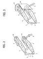
- figure 2 is a perspective schematic view of a welding head according to the invention,
- figure 3 shows a further embodiment of the welding head according to the invention.
- In figure 1,
reference number 1 indicates generally an electric spot welding head, of conventional type, with remote transformer (not illustrated in the drawings), suited for manual use. - The head comprises a pair of
electrodes 2 opposed to each other, provided on the tip of twoterminal portions 3, for example L shaped, the shape however depending on the type of electrode used for a specific operation, theseterminal portions 3 projecting from the front ends of two supportingelements 4 which are of a substantially elongated shape and provided withrespective appendices - The two
electrode holding elements 4 are connected to the ends of a fluid actuator 6, for example a pneumatic cylinder, at their rear ends. - The ends of a tubular sheath 7 are rigidly connected to the two rear ends of the supporting
elements 4; anelectrical conductor 8 is guided into this tubular sheath 7 (only diagrammatically illustrated in the drawing), theelectrical conductor 8 being electrically connected to one of theelectrodes 2 and extending into anothertubular sheath 9 connected to a terminal of the transformer. - A further
electric conductor 10 is also guided into thetubular sheath 9 thereby connecting the other terminal of the transformer to theother electrode 2. - When the welding head is operating, electric current coming from conductor 10 (see arrows in the drawing), goes into its
respective electrode 2 and afterwards from there, through the metal parts to be welded (not shown) and which are pressed between the electrodes, into theother electrode 2 and from there around the transformer throughconductor 8. - Actuator 6 is activated to move electrodes between an open condition and a closed operative condition for welding. Further cables and tubes are guided into
tubular sheaths 7, 9 for supplementary services such as compressed air supply to pneumatic cylinder 6 and cooling fluid for the electrodes. - As already referred above, high electric current flowing through
conductor 8 generates a relatively high induced magnetic field relatively high and close to the operator's body placed behind the welding head. - In order to avoid such a drawback, the present invention provides the welding head diagrammatically shown in figure 2. In this figure, parts in common with figure 1 are indicated with the same reference numbers. Moreover figure 2 is adapted to essentially show the main portions of the two
electrodes 4 and relative supporting elements thereof, and for greater clarity it fails to show the pivot connection between the two electrodes and the actuator driving the two electrodes between open and closed positions. These parts, omitted in figure 2, can be made in any known way and, taken by themselves don't form part of the present invention. Moreover omitting these details from figure 2 make this one more readily understandable. - The main difference from figure 1 consists in that in the case of the welding head according to the invention and shown in figure 2, the loop-shaped tubular sheath 7 extends substantially into a plane lying parallel and side by side to the plane defined by the two electrodes' bodies and is substantially centred with respect to these electrodes, so that the sheath's loop portion 7 stands in front of the circuit defined by the two electrodes' bodies and the electrodes themselves.
- As indicated by arrows in figure 2, electric current flows through sheath's loop portion 7 and the loop portion defined by the two electrodes respectively in two opposite directions of rotation, so that the magnetic fields induced by current flowing through
conductor 8 placed into the tubular sheath 7 and through supportingelements 4 andelectrodes 2 cancel each other out or anyway result in a relatively reduced residual magnetic field. - Furthermore, as it can be seen, the sheath loop portion 7 is closer to the welding head's front end and therefore lies farther from the operator's body, in the case the welding head is operated manually.
- As shown in figure 2, the ends 7 of the sheath loop portion are connected to two connecting
members 11 of tubular shape (or also of a different geometry) having a curved configuration and a relatively stiff structure, so that sheath 7 keeps substantially its configuration and its position in any condition, except for deformations caused by electrodes moving around their respective axis of articulation. - As it can be seen, sheath 7 comprises two rectilinear and parallel reciprocally spaced extensions which are connected by a curved portion. The length of the rectilinear portions may also be chosen in order to obtain the best result in terms of nullification or reduction of the overall magnetic field.
- As already described, loop portion 7 is centred with respect to the median axis which is parallel and intermediate between the longitudinal directions of the electrode supporting elements, so as to face the loop portion defined by
elements 4 andelectrodes 2, for reducing the overall magnetic field as much as possible. - In the embodiment represented in figure 2, operator's safety is further increased by providing a
protection shield 12, for example made of aluminium, connected to a bearing structure or to the body of one electrode. - Of course, without prejudice to the principle of the invention, the details of construction and the embodiments may vary widely with respect to what is described and illustrated herein, without thereby departing from the scope of the present invention as defined in the ensuing claims.
Claims (5)
- Spot welding head (1),
of the type comprising:- a pair of electrodes (2) supported by respective supporting bodies (4) and movable with respect to each other between an open position and a closed position,- an actuator device (6) to control the movement of the electrodes between the open position and the closed position,- electric conductors (8,10) connecting the two electrodes (2) to the terminals of a transformer which is located at a remote position with respect to the welding head (1), and- a tubular sheath portion (7), into which at least part of at least one (8) of the aforesaid electrical conductors is guided, having a loop portion with ends rigidly connected to the rear ends of the supporting bodies of the electrodes,characterised in that said loop-shaped sheath (7) is disposed in such a way that the magnetic field generated by electromagnetic induction caused by electric current flowing through the electric conductor (8) placed into the loop-shaped sheath (7), and magnetic field generated by electromagnetic induction caused by electric current flowing through the two electrodes (2) and through the supporting bodies (4) of the two electrodes, substantially cancel each other out or anyway generate an overall magnetic field sensibly reduced and located forwardly with respect to the rear end of the welding head or anyway spaced forwardly away from the operator's body. - Spot welding head (1), according to claim 1, characterised in that said tubular sheath loop portion (7) extends into a plane lying substantially parallel and side by side to the plane defined by the bodies of the two electrodes, said loop portion being substantially centred with respect to a median direction (15) which is parallel and intermediate between the longitudinal directions of said electrode supporting bodies (4), so that the sheath loop portion (7) faces the annular path defined by the electrodes (2) and the supporting bodies (4) thereof.
- Spot welding head (1), according to claim 2, characterised in that the arrangement is such that the electric conductor (8) placed into said loop portion is passed through by a current moving in a direction of rotation opposite to that of the current through the two electrodes (2).
- Spot welding head(1), according to claim 1, characterised in that the welding head is provided with a protection shield (12) on its rear side, for example made of aluminium, in order to protect the operator from any residual magnetic field generated by current flowing through the welding head.
- Spot welding head (1), according to claim 1, characterised in that the loop-shaped sheath (7) comprises two substantially rectilinear stiff extensions, parallel and spaced from each other, which at one end are connected together through a curved portion and at the other end are respectively connected to the rear ends of the electrode supporting bodies (4) through two substantially stiff curved portions (11).
Priority Applications (8)
| Application Number | Priority Date | Filing Date | Title |
|---|---|---|---|
| ES06425154T ES2306410T3 (en) | 2006-03-08 | 2006-03-08 | HEAD OF ELECTRICAL WELDING BY POINTS. |
| EP06425154A EP1832372B1 (en) | 2006-03-08 | 2006-03-08 | Electric spot welding head |
| AT06425154T ATE395157T1 (en) | 2006-03-08 | 2006-03-08 | ELECTRIC SPOT WELDING HEAD |
| PL06425154T PL1832372T3 (en) | 2006-03-08 | 2006-03-08 | Electric spot welding head |
| DE602006001198T DE602006001198D1 (en) | 2006-03-08 | 2006-03-08 | Electric spot welding head |
| US11/683,151 US7851723B2 (en) | 2006-03-08 | 2007-03-07 | Electric spot welding head |
| JP2007056737A JP4949082B2 (en) | 2006-03-08 | 2007-03-07 | Electric spot welding head |
| CNB2007100857255A CN100542729C (en) | 2006-03-08 | 2007-03-08 | Electric spot welding head |
Applications Claiming Priority (1)
| Application Number | Priority Date | Filing Date | Title |
|---|---|---|---|
| EP06425154A EP1832372B1 (en) | 2006-03-08 | 2006-03-08 | Electric spot welding head |
Publications (2)
| Publication Number | Publication Date |
|---|---|
| EP1832372A1 true EP1832372A1 (en) | 2007-09-12 |
| EP1832372B1 EP1832372B1 (en) | 2008-05-14 |
Family
ID=36685786
Family Applications (1)
| Application Number | Title | Priority Date | Filing Date |
|---|---|---|---|
| EP06425154A Expired - Lifetime EP1832372B1 (en) | 2006-03-08 | 2006-03-08 | Electric spot welding head |
Country Status (8)
| Country | Link |
|---|---|
| US (1) | US7851723B2 (en) |
| EP (1) | EP1832372B1 (en) |
| JP (1) | JP4949082B2 (en) |
| CN (1) | CN100542729C (en) |
| AT (1) | ATE395157T1 (en) |
| DE (1) | DE602006001198D1 (en) |
| ES (1) | ES2306410T3 (en) |
| PL (1) | PL1832372T3 (en) |
Cited By (2)
| Publication number | Priority date | Publication date | Assignee | Title |
|---|---|---|---|---|
| WO2015035255A1 (en) * | 2013-09-06 | 2015-03-12 | Amada Miyachi America, Inc. | Weld head |
| CN113414484A (en) * | 2021-06-08 | 2021-09-21 | 中国第一汽车股份有限公司 | Special-shaped manual welding tongs for transverse operation |
Families Citing this family (2)
| Publication number | Priority date | Publication date | Assignee | Title |
|---|---|---|---|---|
| KR101509694B1 (en) * | 2013-03-26 | 2015-04-07 | 현대자동차 주식회사 | Cooling structure of spot welding device |
| CN115213579B (en) * | 2022-06-22 | 2024-08-13 | 首钢集团有限公司 | Control method and device for salient points on surface of welding spot of coated steel plate |
Citations (5)
| Publication number | Priority date | Publication date | Assignee | Title |
|---|---|---|---|---|
| US2491169A (en) * | 1945-06-06 | 1949-12-13 | Gen Motors Corp | Large throat portable welder |
| US4208566A (en) * | 1978-07-18 | 1980-06-17 | Ab Volvo | Spot welding device |
| JPH01150483A (en) * | 1987-12-08 | 1989-06-13 | Suzuki Motor Co Ltd | Method for feeding current to large current machine |
| US20030089684A1 (en) * | 1999-08-17 | 2003-05-15 | Beauregard Peter G. | Modular welding guns |
| WO2005115673A2 (en) * | 2004-05-27 | 2005-12-08 | Fronius International Gmbh | Welding current supply system |
Family Cites Families (9)
| Publication number | Priority date | Publication date | Assignee | Title |
|---|---|---|---|---|
| US4237365A (en) * | 1978-12-06 | 1980-12-02 | Emerson Electric Co. | Combination arc brazing and welding electrode holder |
| JPS5699081A (en) * | 1980-01-11 | 1981-08-10 | Nec Corp | Resistance welder |
| JPS60255286A (en) * | 1984-05-31 | 1985-12-16 | Mitsubishi Electric Corp | Spot welding machine |
| JPS6281276A (en) * | 1985-10-04 | 1987-04-14 | Nissan Motor Co Ltd | Spot welding gun |
| US4973813A (en) * | 1989-09-25 | 1990-11-27 | Shirley Mitchell | System for monitoring weld parameters |
| US5616969A (en) * | 1995-07-11 | 1997-04-01 | Morava; Irena | Power distribution system having substantially zero electromagnetic field radiation |
| US6909064B2 (en) * | 2003-04-07 | 2005-06-21 | Progressive Tool & Industries Co. | Pinch weld gun with swivel shunt connection |
| US6891102B2 (en) * | 2003-04-21 | 2005-05-10 | Abul Rashid | Electromagnetic radiation insulated electrical appliance |
| US20070119069A1 (en) * | 2005-11-30 | 2007-05-31 | Youngtack Shim | Electromagnetically-shielded hair drying systems and methods |
-
2006
- 2006-03-08 EP EP06425154A patent/EP1832372B1/en not_active Expired - Lifetime
- 2006-03-08 ES ES06425154T patent/ES2306410T3/en not_active Expired - Lifetime
- 2006-03-08 DE DE602006001198T patent/DE602006001198D1/en not_active Expired - Lifetime
- 2006-03-08 AT AT06425154T patent/ATE395157T1/en active
- 2006-03-08 PL PL06425154T patent/PL1832372T3/en unknown
-
2007
- 2007-03-07 US US11/683,151 patent/US7851723B2/en active Active
- 2007-03-07 JP JP2007056737A patent/JP4949082B2/en not_active Expired - Fee Related
- 2007-03-08 CN CNB2007100857255A patent/CN100542729C/en not_active Expired - Fee Related
Patent Citations (5)
| Publication number | Priority date | Publication date | Assignee | Title |
|---|---|---|---|---|
| US2491169A (en) * | 1945-06-06 | 1949-12-13 | Gen Motors Corp | Large throat portable welder |
| US4208566A (en) * | 1978-07-18 | 1980-06-17 | Ab Volvo | Spot welding device |
| JPH01150483A (en) * | 1987-12-08 | 1989-06-13 | Suzuki Motor Co Ltd | Method for feeding current to large current machine |
| US20030089684A1 (en) * | 1999-08-17 | 2003-05-15 | Beauregard Peter G. | Modular welding guns |
| WO2005115673A2 (en) * | 2004-05-27 | 2005-12-08 | Fronius International Gmbh | Welding current supply system |
Non-Patent Citations (2)
| Title |
|---|
| F BÖRNER: "Focus on BIA's work", November 2003, BERUFGEBOSSENSCHAFTLICHES INSTITUT FÜR ARBEITSSCHUTZ, SANKT AUGUSTIN, GERMANY, XP002392804 * |
| PATENT ABSTRACTS OF JAPAN vol. 013, no. 411 (M - 869) 11 September 1989 (1989-09-11) * |
Cited By (3)
| Publication number | Priority date | Publication date | Assignee | Title |
|---|---|---|---|---|
| WO2015035255A1 (en) * | 2013-09-06 | 2015-03-12 | Amada Miyachi America, Inc. | Weld head |
| US10086468B2 (en) | 2013-09-06 | 2018-10-02 | Amada Miyachi America, Inc. | Weld head |
| CN113414484A (en) * | 2021-06-08 | 2021-09-21 | 中国第一汽车股份有限公司 | Special-shaped manual welding tongs for transverse operation |
Also Published As
| Publication number | Publication date |
|---|---|
| US20070210033A1 (en) | 2007-09-13 |
| JP4949082B2 (en) | 2012-06-06 |
| DE602006001198D1 (en) | 2008-06-26 |
| PL1832372T3 (en) | 2008-10-31 |
| ES2306410T3 (en) | 2008-11-01 |
| US7851723B2 (en) | 2010-12-14 |
| CN100542729C (en) | 2009-09-23 |
| JP2007237296A (en) | 2007-09-20 |
| CN101032781A (en) | 2007-09-12 |
| EP1832372B1 (en) | 2008-05-14 |
| ATE395157T1 (en) | 2008-05-15 |
Similar Documents
| Publication | Publication Date | Title |
|---|---|---|
| US7851723B2 (en) | Electric spot welding head | |
| CN114220718B (en) | DC circuit breaker | |
| AU2006202478B2 (en) | Improved contactor for welding wire feeder | |
| US20150181686A1 (en) | High access consumables for a plasma arc cutting system | |
| JP2580029B2 (en) | Variable-pitch spot welding gun device for welding robot | |
| JP2018134681A (en) | Electrical resistance welding head with electrodes arranged on the same side | |
| CN111482685A (en) | High accessibility consumables for plasma arc cutting systems | |
| US6066832A (en) | Welding arc voltage sense lead | |
| EP3331660B1 (en) | Connector, connection system and related methods for connecting a plasma torch to a generator | |
| WO2020171086A1 (en) | Electric circuit breaker device | |
| KR20180089278A (en) | Arc welding device, arc welding method, and magnetism control device for arc welding | |
| EP4251359B1 (en) | Trigger mechanism with rotating power connector for a semi automatic welding torch | |
| JP7022596B2 (en) | Electromagnetic relay | |
| US6259050B1 (en) | Burn-off contact arrangement | |
| JP5780398B2 (en) | Spot welder | |
| US9505079B2 (en) | High capacity aluminum spot welding trans-gun primary cable | |
| GB1571589A (en) | Electrical contact arrangement | |
| CN215280318U (en) | Novel manual water-cooling MIMAG welding gun | |
| US5276296A (en) | Welding gun apparatus | |
| EP3681665A1 (en) | Welding or plasma torch with an interface comprising guide means with spherical portions, and device employing this torch | |
| JP2009247876A (en) | Monopolar type high frequency treatment device for endoscope | |
| US20240316680A1 (en) | Floating core tube in welding torch cables | |
| US4493986A (en) | Pistol grip electrical brazing tool | |
| WO2024197129A1 (en) | Welding torch cables with floating core tube | |
| JP4422554B2 (en) | Vacuum circuit breaker |
Legal Events
| Date | Code | Title | Description |
|---|---|---|---|
| PUAI | Public reference made under article 153(3) epc to a published international application that has entered the european phase |
Free format text: ORIGINAL CODE: 0009012 |
|
| 17P | Request for examination filed |
Effective date: 20070118 |
|
| AK | Designated contracting states |
Kind code of ref document: A1 Designated state(s): AT BE BG CH CY CZ DE DK EE ES FI FR GB GR HU IE IS IT LI LT LU LV MC NL PL PT RO SE SI SK TR |
|
| AX | Request for extension of the european patent |
Extension state: AL BA HR MK YU |
|
| GRAP | Despatch of communication of intention to grant a patent |
Free format text: ORIGINAL CODE: EPIDOSNIGR1 |
|
| GRAS | Grant fee paid |
Free format text: ORIGINAL CODE: EPIDOSNIGR3 |
|
| GRAA | (expected) grant |
Free format text: ORIGINAL CODE: 0009210 |
|
| AK | Designated contracting states |
Kind code of ref document: B1 Designated state(s): AT BE BG CH CY CZ DE DK EE ES FI FR GB GR HU IE IS IT LI LT LU LV MC NL PL PT RO SE SI SK TR |
|
| REG | Reference to a national code |
Ref country code: GB Ref legal event code: FG4D |
|
| AKX | Designation fees paid |
Designated state(s): AT BE BG CH CY CZ DE DK EE ES FI FR GB GR HU IE IS IT LI LT LU LV MC NL PL PT RO SE SI SK TR |
|
| REG | Reference to a national code |
Ref country code: CH Ref legal event code: EP |
|
| REG | Reference to a national code |
Ref country code: IE Ref legal event code: FG4D Free format text: LANGUAGE OF EP DOCUMENT: FRENCH |
|
| REF | Corresponds to: |
Ref document number: 602006001198 Country of ref document: DE Date of ref document: 20080626 Kind code of ref document: P |
|
| REG | Reference to a national code |
Ref country code: SE Ref legal event code: TRGR |
|
| REG | Reference to a national code |
Ref country code: RO Ref legal event code: EPE |
|
| PG25 | Lapsed in a contracting state [announced via postgrant information from national office to epo] |
Ref country code: SI Free format text: LAPSE BECAUSE OF FAILURE TO SUBMIT A TRANSLATION OF THE DESCRIPTION OR TO PAY THE FEE WITHIN THE PRESCRIBED TIME-LIMIT Effective date: 20080514 |
|
| PG25 | Lapsed in a contracting state [announced via postgrant information from national office to epo] |
Ref country code: FI Free format text: LAPSE BECAUSE OF FAILURE TO SUBMIT A TRANSLATION OF THE DESCRIPTION OR TO PAY THE FEE WITHIN THE PRESCRIBED TIME-LIMIT Effective date: 20080514 |
|
| REG | Reference to a national code |
Ref country code: PL Ref legal event code: T3 |
|
| REG | Reference to a national code |
Ref country code: ES Ref legal event code: FG2A Ref document number: 2306410 Country of ref document: ES Kind code of ref document: T3 |
|
| NLV1 | Nl: lapsed or annulled due to failure to fulfill the requirements of art. 29p and 29m of the patents act | ||
| PG25 | Lapsed in a contracting state [announced via postgrant information from national office to epo] |
Ref country code: LV Free format text: LAPSE BECAUSE OF FAILURE TO SUBMIT A TRANSLATION OF THE DESCRIPTION OR TO PAY THE FEE WITHIN THE PRESCRIBED TIME-LIMIT Effective date: 20080514 Ref country code: NL Free format text: LAPSE BECAUSE OF FAILURE TO SUBMIT A TRANSLATION OF THE DESCRIPTION OR TO PAY THE FEE WITHIN THE PRESCRIBED TIME-LIMIT Effective date: 20080514 |
|
| PG25 | Lapsed in a contracting state [announced via postgrant information from national office to epo] |
Ref country code: IS Free format text: LAPSE BECAUSE OF FAILURE TO SUBMIT A TRANSLATION OF THE DESCRIPTION OR TO PAY THE FEE WITHIN THE PRESCRIBED TIME-LIMIT Effective date: 20080914 |
|
| PG25 | Lapsed in a contracting state [announced via postgrant information from national office to epo] |
Ref country code: LT Free format text: LAPSE BECAUSE OF FAILURE TO SUBMIT A TRANSLATION OF THE DESCRIPTION OR TO PAY THE FEE WITHIN THE PRESCRIBED TIME-LIMIT Effective date: 20080514 Ref country code: DK Free format text: LAPSE BECAUSE OF FAILURE TO SUBMIT A TRANSLATION OF THE DESCRIPTION OR TO PAY THE FEE WITHIN THE PRESCRIBED TIME-LIMIT Effective date: 20080514 Ref country code: CZ Free format text: LAPSE BECAUSE OF FAILURE TO SUBMIT A TRANSLATION OF THE DESCRIPTION OR TO PAY THE FEE WITHIN THE PRESCRIBED TIME-LIMIT Effective date: 20080514 |
|
| PG25 | Lapsed in a contracting state [announced via postgrant information from national office to epo] |
Ref country code: BE Free format text: LAPSE BECAUSE OF FAILURE TO SUBMIT A TRANSLATION OF THE DESCRIPTION OR TO PAY THE FEE WITHIN THE PRESCRIBED TIME-LIMIT Effective date: 20080514 Ref country code: SK Free format text: LAPSE BECAUSE OF FAILURE TO SUBMIT A TRANSLATION OF THE DESCRIPTION OR TO PAY THE FEE WITHIN THE PRESCRIBED TIME-LIMIT Effective date: 20080514 Ref country code: PT Free format text: LAPSE BECAUSE OF FAILURE TO SUBMIT A TRANSLATION OF THE DESCRIPTION OR TO PAY THE FEE WITHIN THE PRESCRIBED TIME-LIMIT Effective date: 20081014 |
|
| PLBE | No opposition filed within time limit |
Free format text: ORIGINAL CODE: 0009261 |
|
| STAA | Information on the status of an ep patent application or granted ep patent |
Free format text: STATUS: NO OPPOSITION FILED WITHIN TIME LIMIT |
|
| 26N | No opposition filed |
Effective date: 20090217 |
|
| PG25 | Lapsed in a contracting state [announced via postgrant information from national office to epo] |
Ref country code: BG Free format text: LAPSE BECAUSE OF FAILURE TO SUBMIT A TRANSLATION OF THE DESCRIPTION OR TO PAY THE FEE WITHIN THE PRESCRIBED TIME-LIMIT Effective date: 20080814 Ref country code: EE Free format text: LAPSE BECAUSE OF FAILURE TO SUBMIT A TRANSLATION OF THE DESCRIPTION OR TO PAY THE FEE WITHIN THE PRESCRIBED TIME-LIMIT Effective date: 20080514 |
|
| PG25 | Lapsed in a contracting state [announced via postgrant information from national office to epo] |
Ref country code: MC Free format text: LAPSE BECAUSE OF NON-PAYMENT OF DUE FEES Effective date: 20090331 |
|
| REG | Reference to a national code |
Ref country code: IE Ref legal event code: MM4A |
|
| PG25 | Lapsed in a contracting state [announced via postgrant information from national office to epo] |
Ref country code: IE Free format text: LAPSE BECAUSE OF NON-PAYMENT OF DUE FEES Effective date: 20090308 |
|
| PG25 | Lapsed in a contracting state [announced via postgrant information from national office to epo] |
Ref country code: GR Free format text: LAPSE BECAUSE OF FAILURE TO SUBMIT A TRANSLATION OF THE DESCRIPTION OR TO PAY THE FEE WITHIN THE PRESCRIBED TIME-LIMIT Effective date: 20080815 |
|
| REG | Reference to a national code |
Ref country code: CH Ref legal event code: PL |
|
| GBPC | Gb: european patent ceased through non-payment of renewal fee |
Effective date: 20100308 |
|
| PG25 | Lapsed in a contracting state [announced via postgrant information from national office to epo] |
Ref country code: LI Free format text: LAPSE BECAUSE OF NON-PAYMENT OF DUE FEES Effective date: 20100331 Ref country code: CH Free format text: LAPSE BECAUSE OF NON-PAYMENT OF DUE FEES Effective date: 20100331 |
|
| PG25 | Lapsed in a contracting state [announced via postgrant information from national office to epo] |
Ref country code: GB Free format text: LAPSE BECAUSE OF NON-PAYMENT OF DUE FEES Effective date: 20100308 |
|
| PG25 | Lapsed in a contracting state [announced via postgrant information from national office to epo] |
Ref country code: LU Free format text: LAPSE BECAUSE OF NON-PAYMENT OF DUE FEES Effective date: 20090308 |
|
| PG25 | Lapsed in a contracting state [announced via postgrant information from national office to epo] |
Ref country code: HU Free format text: LAPSE BECAUSE OF FAILURE TO SUBMIT A TRANSLATION OF THE DESCRIPTION OR TO PAY THE FEE WITHIN THE PRESCRIBED TIME-LIMIT Effective date: 20081115 |
|
| PG25 | Lapsed in a contracting state [announced via postgrant information from national office to epo] |
Ref country code: TR Free format text: LAPSE BECAUSE OF FAILURE TO SUBMIT A TRANSLATION OF THE DESCRIPTION OR TO PAY THE FEE WITHIN THE PRESCRIBED TIME-LIMIT Effective date: 20080514 |
|
| PG25 | Lapsed in a contracting state [announced via postgrant information from national office to epo] |
Ref country code: CY Free format text: LAPSE BECAUSE OF FAILURE TO SUBMIT A TRANSLATION OF THE DESCRIPTION OR TO PAY THE FEE WITHIN THE PRESCRIBED TIME-LIMIT Effective date: 20080514 |
|
| REG | Reference to a national code |
Ref country code: FR Ref legal event code: PLFP Year of fee payment: 11 |
|
| REG | Reference to a national code |
Ref country code: FR Ref legal event code: PLFP Year of fee payment: 12 |
|
| REG | Reference to a national code |
Ref country code: FR Ref legal event code: PLFP Year of fee payment: 13 |
|
| PGFP | Annual fee paid to national office [announced via postgrant information from national office to epo] |
Ref country code: SE Payment date: 20200325 Year of fee payment: 15 Ref country code: AT Payment date: 20200319 Year of fee payment: 15 |
|
| PGFP | Annual fee paid to national office [announced via postgrant information from national office to epo] |
Ref country code: DE Payment date: 20200330 Year of fee payment: 15 |
|
| REG | Reference to a national code |
Ref country code: DE Ref legal event code: R119 Ref document number: 602006001198 Country of ref document: DE |
|
| REG | Reference to a national code |
Ref country code: AT Ref legal event code: MM01 Ref document number: 395157 Country of ref document: AT Kind code of ref document: T Effective date: 20210308 |
|
| PG25 | Lapsed in a contracting state [announced via postgrant information from national office to epo] |
Ref country code: AT Free format text: LAPSE BECAUSE OF NON-PAYMENT OF DUE FEES Effective date: 20210308 Ref country code: SE Free format text: LAPSE BECAUSE OF NON-PAYMENT OF DUE FEES Effective date: 20210309 Ref country code: DE Free format text: LAPSE BECAUSE OF NON-PAYMENT OF DUE FEES Effective date: 20211001 |
|
| PGFP | Annual fee paid to national office [announced via postgrant information from national office to epo] |
Ref country code: RO Payment date: 20240305 Year of fee payment: 19 |
|
| PGFP | Annual fee paid to national office [announced via postgrant information from national office to epo] |
Ref country code: PL Payment date: 20240221 Year of fee payment: 19 Ref country code: FR Payment date: 20240221 Year of fee payment: 19 |
|
| PGFP | Annual fee paid to national office [announced via postgrant information from national office to epo] |
Ref country code: ES Payment date: 20240402 Year of fee payment: 19 |
|
| PGFP | Annual fee paid to national office [announced via postgrant information from national office to epo] |
Ref country code: IT Payment date: 20250218 Year of fee payment: 20 |
|
| PG25 | Lapsed in a contracting state [announced via postgrant information from national office to epo] |
Ref country code: RO Free format text: LAPSE BECAUSE OF NON-PAYMENT OF DUE FEES Effective date: 20250308 |
|
| PG25 | Lapsed in a contracting state [announced via postgrant information from national office to epo] |
Ref country code: FR Free format text: LAPSE BECAUSE OF NON-PAYMENT OF DUE FEES Effective date: 20250331 |
|
| REG | Reference to a national code |
Ref country code: ES Ref legal event code: FD2A Effective date: 20260428 |