EP1832262A1 - Sanitary napkin - Google Patents
Sanitary napkin Download PDFInfo
- Publication number
- EP1832262A1 EP1832262A1 EP05814706A EP05814706A EP1832262A1 EP 1832262 A1 EP1832262 A1 EP 1832262A1 EP 05814706 A EP05814706 A EP 05814706A EP 05814706 A EP05814706 A EP 05814706A EP 1832262 A1 EP1832262 A1 EP 1832262A1
- Authority
- EP
- European Patent Office
- Prior art keywords
- napkin
- projection
- liquid
- sanitary napkin
- body surface
- Prior art date
- Legal status (The legal status is an assumption and is not a legal conclusion. Google has not performed a legal analysis and makes no representation as to the accuracy of the status listed.)
- Withdrawn
Links
- 239000002250 absorbent Substances 0.000 claims abstract description 53
- 239000007788 liquid Substances 0.000 claims abstract description 19
- 230000007423 decrease Effects 0.000 claims abstract description 15
- 230000000630 rising effect Effects 0.000 claims description 6
- 239000010410 layer Substances 0.000 description 50
- 239000000853 adhesive Substances 0.000 description 32
- 230000001070 adhesive effect Effects 0.000 description 32
- 239000004745 nonwoven fabric Substances 0.000 description 20
- 239000000463 material Substances 0.000 description 19
- 210000001215 vagina Anatomy 0.000 description 15
- 210000000436 anus Anatomy 0.000 description 14
- 239000008280 blood Substances 0.000 description 10
- 210000004369 blood Anatomy 0.000 description 10
- 230000002175 menstrual effect Effects 0.000 description 10
- 238000012986 modification Methods 0.000 description 10
- 230000004048 modification Effects 0.000 description 10
- 239000012943 hotmelt Substances 0.000 description 9
- 230000003014 reinforcing effect Effects 0.000 description 9
- 239000004820 Pressure-sensitive adhesive Substances 0.000 description 8
- 238000010276 construction Methods 0.000 description 8
- 230000002745 absorbent Effects 0.000 description 6
- 230000006835 compression Effects 0.000 description 6
- 238000007906 compression Methods 0.000 description 6
- 239000000835 fiber Substances 0.000 description 6
- -1 polyethylene Polymers 0.000 description 6
- 210000001217 buttock Anatomy 0.000 description 4
- 229920000139 polyethylene terephthalate Polymers 0.000 description 4
- 239000005020 polyethylene terephthalate Substances 0.000 description 4
- 239000011347 resin Substances 0.000 description 4
- 229920005989 resin Polymers 0.000 description 4
- 239000004698 Polyethylene Substances 0.000 description 3
- 229920000573 polyethylene Polymers 0.000 description 3
- 229920000247 superabsorbent polymer Polymers 0.000 description 3
- 241001313288 Labia Species 0.000 description 2
- GWEVSGVZZGPLCZ-UHFFFAOYSA-N Titan oxide Chemical compound O=[Ti]=O GWEVSGVZZGPLCZ-UHFFFAOYSA-N 0.000 description 2
- 238000013459 approach Methods 0.000 description 2
- 239000000839 emulsion Substances 0.000 description 2
- 239000006260 foam Substances 0.000 description 2
- 230000005484 gravity Effects 0.000 description 2
- 239000011256 inorganic filler Substances 0.000 description 2
- 229910003475 inorganic filler Inorganic materials 0.000 description 2
- 230000000717 retained effect Effects 0.000 description 2
- OGIDPMRJRNCKJF-UHFFFAOYSA-N titanium oxide Inorganic materials [Ti]=O OGIDPMRJRNCKJF-UHFFFAOYSA-N 0.000 description 2
- 244000043261 Hevea brasiliensis Species 0.000 description 1
- 239000004743 Polypropylene Substances 0.000 description 1
- 229920000297 Rayon Polymers 0.000 description 1
- 230000001154 acute effect Effects 0.000 description 1
- 238000007792 addition Methods 0.000 description 1
- 238000004026 adhesive bonding Methods 0.000 description 1
- 239000011230 binding agent Substances 0.000 description 1
- 238000013461 design Methods 0.000 description 1
- 229920001971 elastomer Polymers 0.000 description 1
- 230000012447 hatching Effects 0.000 description 1
- 238000010438 heat treatment Methods 0.000 description 1
- 238000003475 lamination Methods 0.000 description 1
- CNQCVBJFEGMYDW-UHFFFAOYSA-N lawrencium atom Chemical compound [Lr] CNQCVBJFEGMYDW-UHFFFAOYSA-N 0.000 description 1
- 238000005259 measurement Methods 0.000 description 1
- 238000000034 method Methods 0.000 description 1
- 239000000203 mixture Substances 0.000 description 1
- 229920003052 natural elastomer Polymers 0.000 description 1
- 229920001194 natural rubber Polymers 0.000 description 1
- 229920013716 polyethylene resin Polymers 0.000 description 1
- 229920001155 polypropylene Polymers 0.000 description 1
- 229920002635 polyurethane Polymers 0.000 description 1
- 239000004814 polyurethane Substances 0.000 description 1
- 238000003825 pressing Methods 0.000 description 1
- 239000002964 rayon Substances 0.000 description 1
- 239000005060 rubber Substances 0.000 description 1
- 239000002344 surface layer Substances 0.000 description 1
- 229920003051 synthetic elastomer Polymers 0.000 description 1
- 239000005061 synthetic rubber Substances 0.000 description 1
- 238000012546 transfer Methods 0.000 description 1
Images






Classifications
-
- A—HUMAN NECESSITIES
- A61—MEDICAL OR VETERINARY SCIENCE; HYGIENE
- A61F—FILTERS IMPLANTABLE INTO BLOOD VESSELS; PROSTHESES; DEVICES PROVIDING PATENCY TO, OR PREVENTING COLLAPSING OF, TUBULAR STRUCTURES OF THE BODY, e.g. STENTS; ORTHOPAEDIC, NURSING OR CONTRACEPTIVE DEVICES; FOMENTATION; TREATMENT OR PROTECTION OF EYES OR EARS; BANDAGES, DRESSINGS OR ABSORBENT PADS; FIRST-AID KITS
- A61F13/00—Bandages or dressings; Absorbent pads
- A61F13/15—Absorbent pads, e.g. sanitary towels, swabs or tampons for external or internal application to the body; Supporting or fastening means therefor; Tampon applicators
- A61F13/45—Absorbent pads, e.g. sanitary towels, swabs or tampons for external or internal application to the body; Supporting or fastening means therefor; Tampon applicators characterised by the shape
- A61F13/47—Sanitary towels, incontinence pads or napkins
- A61F13/475—Sanitary towels, incontinence pads or napkins characterised by edge leakage prevention means
- A61F13/4758—Sanitary towels, incontinence pads or napkins characterised by edge leakage prevention means the means preventing fluid flow in a longitudinal direction
-
- A—HUMAN NECESSITIES
- A61—MEDICAL OR VETERINARY SCIENCE; HYGIENE
- A61F—FILTERS IMPLANTABLE INTO BLOOD VESSELS; PROSTHESES; DEVICES PROVIDING PATENCY TO, OR PREVENTING COLLAPSING OF, TUBULAR STRUCTURES OF THE BODY, e.g. STENTS; ORTHOPAEDIC, NURSING OR CONTRACEPTIVE DEVICES; FOMENTATION; TREATMENT OR PROTECTION OF EYES OR EARS; BANDAGES, DRESSINGS OR ABSORBENT PADS; FIRST-AID KITS
- A61F13/00—Bandages or dressings; Absorbent pads
- A61F13/15—Absorbent pads, e.g. sanitary towels, swabs or tampons for external or internal application to the body; Supporting or fastening means therefor; Tampon applicators
- A61F13/45—Absorbent pads, e.g. sanitary towels, swabs or tampons for external or internal application to the body; Supporting or fastening means therefor; Tampon applicators characterised by the shape
- A61F13/47—Sanitary towels, incontinence pads or napkins
- A61F13/472—Sanitary towels, incontinence pads or napkins specially adapted for female use
-
- A—HUMAN NECESSITIES
- A61—MEDICAL OR VETERINARY SCIENCE; HYGIENE
- A61F—FILTERS IMPLANTABLE INTO BLOOD VESSELS; PROSTHESES; DEVICES PROVIDING PATENCY TO, OR PREVENTING COLLAPSING OF, TUBULAR STRUCTURES OF THE BODY, e.g. STENTS; ORTHOPAEDIC, NURSING OR CONTRACEPTIVE DEVICES; FOMENTATION; TREATMENT OR PROTECTION OF EYES OR EARS; BANDAGES, DRESSINGS OR ABSORBENT PADS; FIRST-AID KITS
- A61F13/00—Bandages or dressings; Absorbent pads
- A61F13/15—Absorbent pads, e.g. sanitary towels, swabs or tampons for external or internal application to the body; Supporting or fastening means therefor; Tampon applicators
-
- A—HUMAN NECESSITIES
- A61—MEDICAL OR VETERINARY SCIENCE; HYGIENE
- A61F—FILTERS IMPLANTABLE INTO BLOOD VESSELS; PROSTHESES; DEVICES PROVIDING PATENCY TO, OR PREVENTING COLLAPSING OF, TUBULAR STRUCTURES OF THE BODY, e.g. STENTS; ORTHOPAEDIC, NURSING OR CONTRACEPTIVE DEVICES; FOMENTATION; TREATMENT OR PROTECTION OF EYES OR EARS; BANDAGES, DRESSINGS OR ABSORBENT PADS; FIRST-AID KITS
- A61F13/00—Bandages or dressings; Absorbent pads
- A61F13/15—Absorbent pads, e.g. sanitary towels, swabs or tampons for external or internal application to the body; Supporting or fastening means therefor; Tampon applicators
- A61F13/45—Absorbent pads, e.g. sanitary towels, swabs or tampons for external or internal application to the body; Supporting or fastening means therefor; Tampon applicators characterised by the shape
- A61F13/47—Sanitary towels, incontinence pads or napkins
- A61F13/472—Sanitary towels, incontinence pads or napkins specially adapted for female use
- A61F13/47218—Sanitary towels, incontinence pads or napkins specially adapted for female use with a raised crotch region, e.g. hump
-
- A—HUMAN NECESSITIES
- A61—MEDICAL OR VETERINARY SCIENCE; HYGIENE
- A61F—FILTERS IMPLANTABLE INTO BLOOD VESSELS; PROSTHESES; DEVICES PROVIDING PATENCY TO, OR PREVENTING COLLAPSING OF, TUBULAR STRUCTURES OF THE BODY, e.g. STENTS; ORTHOPAEDIC, NURSING OR CONTRACEPTIVE DEVICES; FOMENTATION; TREATMENT OR PROTECTION OF EYES OR EARS; BANDAGES, DRESSINGS OR ABSORBENT PADS; FIRST-AID KITS
- A61F13/00—Bandages or dressings; Absorbent pads
- A61F13/15—Absorbent pads, e.g. sanitary towels, swabs or tampons for external or internal application to the body; Supporting or fastening means therefor; Tampon applicators
- A61F13/45—Absorbent pads, e.g. sanitary towels, swabs or tampons for external or internal application to the body; Supporting or fastening means therefor; Tampon applicators characterised by the shape
- A61F13/47—Sanitary towels, incontinence pads or napkins
- A61F13/472—Sanitary towels, incontinence pads or napkins specially adapted for female use
- A61F13/47263—Sanitary towels, incontinence pads or napkins specially adapted for female use with activating means, e.g. elastic, heat or chemical activatable means
-
- A—HUMAN NECESSITIES
- A61—MEDICAL OR VETERINARY SCIENCE; HYGIENE
- A61F—FILTERS IMPLANTABLE INTO BLOOD VESSELS; PROSTHESES; DEVICES PROVIDING PATENCY TO, OR PREVENTING COLLAPSING OF, TUBULAR STRUCTURES OF THE BODY, e.g. STENTS; ORTHOPAEDIC, NURSING OR CONTRACEPTIVE DEVICES; FOMENTATION; TREATMENT OR PROTECTION OF EYES OR EARS; BANDAGES, DRESSINGS OR ABSORBENT PADS; FIRST-AID KITS
- A61F13/00—Bandages or dressings; Absorbent pads
- A61F13/15—Absorbent pads, e.g. sanitary towels, swabs or tampons for external or internal application to the body; Supporting or fastening means therefor; Tampon applicators
- A61F13/51—Absorbent pads, e.g. sanitary towels, swabs or tampons for external or internal application to the body; Supporting or fastening means therefor; Tampon applicators characterised by the outer layers of the pads
- A61F13/511—Topsheet, i.e. the permeable cover or layer facing the skin
Definitions
- the present invention relates to a sanitary napkin with a projection disposed on a body surface of a napkin body and more particularly to a sanitary napkin whose projection can easily conform to the contours of the woman's body so as to be effective in preventing leakage of menstrual blood.
- Japanese Unexamined Patent Application Publication No. H11-513921 discloses a sanitary napkin in which a primary absorbent component having a generally triangular cross section is disposed on a body surface of a secondary absorbent component being a napkin body.
- the primary absorbent component is constructed by wrapping a hydrophilic foam structure in an outer cover. The cross-sectional shape of the primary absorbent component does not change over the length of the sanitary napkin.
- Japanese Unexamined Patent Application Publication No. H09-313529 discloses a sanitary napkin whose upper surface layer is centrally folded to form a jetty.
- This jetty has longitudinally-extending elastic members in its right and left side portions and is raised from the body surface of the napkin body under elastic tension exerted by the elastic members.
- the jetty extends longitudinally of the sanitary napkin with a uniform width.
- Japanese Unexamined Patent Application Publication No. 2002-320638 discloses a sanitary napkin in which a T-section three-dimensional wall formed of a liquid-permeable sheet is disposed on the body surface of the napkin body.
- This three-dimensional wall has elastic members for exerting a longitudinal contractive force and is raised from the body surface of the napkin body when the napkin body is curved with front and rear edges of the napkin body being drawn closer to each other by the elastic members.
- the width of the three-dimensional wall does not change over the length of the napkin body.
- Japanese Unexamined Patent Application Publication No. 2001-504727 discloses a sanitary napkin which has a liquid-absorbent layer and a topsheet disposed on a body surface of the liquid-absorbent layer with an absorbent body and a stiffening element interposed between the liquid-absorbent layer and the topsheet.
- the topsheet, the absorbent body, and the stiffening element form a hump having a generally triangular cross section. In the hump, both the width and height gradually increases from the front end to the center and gradually decreases from the center to the rear end.
- a projection designed to fit against the wearer's body is disposed on the body surface of the napkin body so as to prevent leakage of liquid such as menstrual blood.
- the cleft In the woman's crotch, however, the cleft varies in shape anteroposteriorly to have different opening widths and depths for different regions. Around the vaginal opening and the labia majora, the cleft has a relatively large opening width. Near and behind the anus, the cleft lies between the buttocks. The cleft between the buttocks (or the intergluteal cleft) becomes the deepest behind the anus and then shallower toward the coccyx.
- the liquid-absorbent layer of the sanitary napkin can effectively absorb liquid such as menstrual blood discharged from the vaginal opening, moreover, the sanitary napkin is required to reliably fit on the vaginal opening and its vicinity.
- the projection is uniform in width and does not change much in height over the length of the projection. Therefore, the projection, which is not in conformity with the contours of the woman's crotch, may cause a problem of failing to snugly fit on the vaginal opening or to reliably find its way into the intergluteal cleft.
- both the width and the height become the largest centrally of the projection.
- the projection tends to make a wearer feel uncomfortable because it is too high.
- the projection cannot easily find its way into the intergluteal cleft because it is too wide.
- the projection tends to create a gap between the napkin body and the buttocks because it is too high.
- the present invention has been developed to solve the problems in the prior art set forth above and has an object to provide a sanitary napkin in which a projection varies in width and height in accordance with the physical features of a woman so as to improve conformity with the body of a woman.
- a sanitary napkin comprising:
- the projection is relatively low at a portion where the width of the projection is relatively large and relatively high at a location where the width of the projection is relatively small.
- the relatively high, narrow portion can easily fit in a deep portion of the intergluteal cleft; the relatively low, wide portion can easily fit on the vaginal opening and its vicinity, in a rear shallow portion of the intergluteal cleft, or on the coccyx and its vicinity.
- the distance between the base ends is larger in a front portion of the projection than in a rear portion behind the front portion.
- the front portion of the projection can easily fit on the vaginal opening and its vicinity, and the rear portion can easily fit in a deep portion of the intergluteal cleft.
- the distance between the base ends is larger in front and rear portions of the projection than in an intermediate portion between the front and rear portions.
- the front portion of the projection can easily fit on the vaginal opening and its vicinity
- the intermediate portion of the projection can easily fit in a deep portion of the intergluteal cleft
- the rear portion of the projection can easily fit in a rear shallow portion of the intergluteal cleft or on the coccyx and its vicinity.
- the distance between the base ends may vary stepwise or continuously.
- a sanitary napkin comprising:
- the second portion can deform independently of the napkin body. Accordingly, when the second portion is located in the intergluteal cleft, a fit of the projection in the intergluteal cleft can easily be maintained even if the napkin body moves laterally.
- the first portion is located forward of the second portion.
- the projection may be adapted to exert a longitudinal elastic contractive force to draw front and rear ends of the napkin body closer to each other and concavely curve the body surface of the napkin body, so that the projection can be raised from the body surface of the napkin body.
- a sanitary napkin comprising:
- the projection is relatively low at a location where the distance between the elastic members is relatively large and relatively high at a location where the distance between the elastic members is relatively small.
- the elastic members may be laterally spaced from each other in a front portion of the projection, but cross each other in a rear portion behind the front portion.
- a sanitary napkin comprising:
- the elastic member of the second portion is not necessarily required to lie right on the longitudinal centerline.
- the elastic member may be spaced from the longitudinal centerline or two or more elastic members may be arranged at a small distance on both sides of the longitudinal centerline. These elastic members may be parallel to each other.
- the body surface of the napkin body may be concavely curved with front and rear ends of the napkin body drawn closer to each other by the elastic contractive force of the elastic members.
- the projection may be formed separately from the napkin body and then secured on the body surface of the napkin body.
- the napkin body may include a topsheet covering the liquid-absorbent layer, and the protrusion may be formed by a part of the topsheet.
- the projection can easily conform to the contours of the woman's body.
- lateral leakage or rearward leakage of liquid such as menstrual blood can be effectively prevented.
- Fig. 1 is a perspective view of a sanitary napkin 1 according to a first embodiment of the present invention in a natural state where no external force is exerted thereon.
- Fig. 2 is a plan view in which a surface element is removed from the sanitary napkin 1 and only a napkin body is flattened.
- Fig. 3 is a sectional view taken along line III-III of Fig. 1
- Fig. 4 is a sectional view taken along line IV-IV of Fig. 1
- Fig. 5 is a sectional view taken along line V-V of Fig. 1
- Fig. 6 is a sectional view taken along line VI-VI of Fig. 1.
- Fig. 7 is a longitudinal sectional view schematically showing a state where the sanitary napkin 1 is applied to the woman's body from the crotch to the buttocks.
- the sanitary napkin as well as its individual components, has two major surfaces: of which one surface intended to be worn toward the wearer's crotch is referred to as “body surface”, while the other surface is referred to as “garment surface”.
- body surface one surface intended to be worn toward the wearer's crotch
- lateral direction the direction perpendicular to the longitudinal direction
- a dimension measured in the longitudinal direction is referred to as “length”
- width a dimension measured in the lateral direction
- Fig. 1 several locations, which are spaced apart from each other in the longitudinal direction of the sanitary napkin 1, are indicated by (a) to (g). Also in Fig. 2, the corresponding locations are indicated by (a) to (g).
- the sanitary napkin 1 comprises a napkin body 2 and a surface element 3 disposed on the body surface of the napkin body 2 to form a projection.
- the napkin body 2 includes a liquid-blocking backsheet 21 on the garment surface side of the napkin body 2, a liquid-absorbent layer 22 disposed on the backsheet 21, and a liquid-permeable topsheet 23 covering the liquid-absorbent layer 22.
- the napkin body 2 has arcuate front and rear edges 4, 5.
- the napkin body 2 is elongated to have a length L1 in the range of 280 to 450 mm.
- the liquid-absorbent layer 22 is also elongated to have arcuate front and rear edges 22a, 22b, which are spaced slightly inward from the front and rear edges 4, 5, respectively.
- the liquid-absorbent layer 22 has right and left side edges 22c, 22c, which extend linearly in parallel to a longitudinal centerline Oy.
- the shape of the right and left side edges 22c, 22c of the liquid-absorbent layer 22 should not be understood as limited to this embodiment.
- the napkin body 2 On laterally opposite sides of the liquid-absorbent layer 22, the napkin body 2 has laterally projecting front flaps 6, 6, laterally projecting fold-back flaps 7, 7, and laterally projecting rear flaps 8, 8 in order from front to rear.
- the front flaps 6, 6, the fold-back flaps 7, 7, and the rear flaps 8, 8, the body surface of the backsheet 21 is covered with a liquid-blocking side sheet 24.
- the liquid-blocking side sheet 24 is bonded to the backsheet 21 through a hot-melt type adhesive.
- the side sheets 24, 24 lie opposite one another with their opposing edges 24a, 24a located inside the side edges 22c, 22c of the liquid-absorbent layer 22 (i.e., located closer to the longitudinal centerline Oy than the side edges 22c, 22c).
- the body surface of the liquid-absorbent layer 22 is covered with the topsheet 23, and the body surface of the topsheet 23 is further covered with the side sheets 24, 24.
- the liquid-permeable topsheet 23 is exposed externally. The overlap between this area and the liquid-absorbent layer 22 is called "main liquid-absorbent region.”
- X1 shown in Fig. 2 represents a vagina-facing reference line, and this vagina-facing reference line X1 is spaced 100 to 200 mm, preferably 100 to 140 mm, for example, about 120 mm, rearward from the front edge 4 of the napkin body 2.
- the vagina-facing reference line X1 as used herein is a target position with which the center of the vaginal opening is to almost coincide when wearing the sanitary napkin 1 along with an undergarment. Leading to this target is through the contour of the sanitary napkin as viewed from the body surface side or the whole design including the arrangement of compression lines on the body surface. Particularly when the fold-back flaps 7, 7 are provided as in the present embodiment, the target usually coincides with the longitudinal centers of the fold-back flaps 7, 7. In the present embodiment, the line passing through the longitudinal centers of the fold-back flaps 7, 7 is taken as the vagina-facing reference line X1.
- X2 shown in Fig. 2 represents an anus-facing reference line, and this anus-facing reference line X2 is intended to face the anus when the vagina-facing reference line X1 coincides with the center of the vaginal opening.
- the anus-facing reference line X2 is usually spaced a distance L2 of 30 to 70 mm, which varies depending on the wearer's body, rearward from the vagina-facing reference line X1.
- X3 shown in Fig. 2 represents a coccyx-facing reference line.
- This coccyx-facing reference line X3 is intended to face the coccyx when the vagina-facing reference line X1 coincides with the center of the vaginal opening.
- the coccyx-facing reference line X3 is usually spaced a distance L3 of 120 to 180 mm, which varies depending on the wearer's body, rearward from the vagina-facing reference line X1.
- the coccyx-facing reference line X3 may be spaced 175 mm rearward from the vagina-facing reference line X1.
- the rear edge 5 of the napkin body 2 and the rear edge 22b of the liquid-absorbent layer 22 are located behind the coccyx-facing reference line X3.
- the napkin body 2 is intended to face the vaginal opening, the anus, and the intergluteal cleft.
- the cleft extending from forward of the vaginal opening to adjacent the coccyx in the woman's body is merely called “cleft”, while the cleft extending from the anus to the coccyx is called “intergluteal cleft”.
- the backsheet 21 may be a film, for example, a polyethylene resin film having a basis weight of about 23.5 g/m 2 , and is preferably permeable to moisture.
- the liquid-absorbent layer 22 may be a mixture of fluff pulp and superabsorbent polymer (SAP) wrapped in a hydrophilic tissue having a basis weight of 18 g/m 2 .
- the fluff pulp may have a weight of about 400 g/m 2 ; the SAP may have a weight of about 12 g/m 2 .
- the side sheet 24 may be a spunbonded nonwoven fabric made of polyethylene/polypropylene sheath/core bicomponent fibers. The spunbonded nonwoven fabric may have a basis weight of about 22 g/m 2 .
- the topsheet 23 may be a through-air bonded nonwoven fabric having a basis weight of about 25 g/m 2 .
- the through-air bonded nonwoven fabric may be made of polyethylene/polyethylene terephthalate sheath/core bicomponent fibers with an inorganic filler such as titanium oxide mixed into the core of polyethylene terephthalate.
- the surface element 3 may have a hydrophilic, liquid-permeable sheet 31.
- the liquid-permeable sheet 31 may be a laminate of first and second liquid-permeable sheets 31a, 31b. As shown in Fig. 3, the first liquid-permeable sheet 31a is an outermost layer, while the second liquid-permeable sheet 31b is located inside the first liquid-permeable sheet 31a.
- the first and second liquid-permeable sheets 31a, 31b may be bonded to each other through a hot-melt type adhesive which is applied in a dot pattern, a spiral pattern, or a striped pattern or sprayed in an emulsion state.
- the first and second liquid-permeable sheets 31a, 31b may be fusion-bonded to each other to have dot-like embossments arranged in such a density as not to interfere with liquid passage.
- the first and second liquid-permeable sheets 31a, 31b may each be a through-air bonded nonwoven fabric having a basis weight of about 25 g/m 2 .
- the through-air bonded nonwoven fabric may be made of polyethylene/polyethylene terephthalate sheath/core bicomponent fibers with an inorganic filler such as titanium oxide mixed into the core of polyethylene terephthalate.
- the first and second liquid-permeable sheets 31a, 31b are not limited to the above-mentioned through-air bonded nonwoven fabric.
- a point-bonded nonwoven fabric there may be used a spunlaced nonwoven fabric, a spunbonded nonwoven fabric, or laminations thereof, such as a spunbonded/meltblown/spunbonded nonwoven fabric.
- the fiber density is preferably 0.12 g/cm 3 or less and the basis weight preferably falls within the range of 15 to 60 g/m 2 so as to improve liquid-permeability.
- the first and second liquid-permeable sheets 31a, 31b may each be a resin film formed with a large number of apertures for liquid passage.
- the apertured resin film may be used as the first liquid-permeable sheet 31a, while the nonwoven fabric such as through-air bonded may be used as the second liquid-permeable sheet 31b.
- the liquid-permeable sheet 31 may be embossed in a dot pattern or corrugated. It is, of course, possible that the liquid-permeable sheet 31 is a single nonwoven fabric.
- the opposite edges of the liquid-permeable sheet 31 are bonded to each other to have a bond 32.
- This bonding may be adhesive-bonding through a hot-melt type adhesive or fusion-bonding.
- the bond 32 is located to face the topsheet 23 of the napkin body 2 and extends along the longitudinal centerline Oy.
- the surface element 3 is bonded to the body surface of the napkin body 2 through a hot-melt type adhesive.
- the bonding region where the surface element 3 is bonded to the body surface of the napkin body 2 is indicated by hatching for the sake of convenience.
- the hot-melt type adhesive may be applied in such a manner as not to interfere with passage of liquid through the topsheet 23.
- the hot-melt type adhesive may be applied in a spiral pattern, a dot pattern, or a striped pattern or sprayed in an emulsion state.
- the bonding region may be divided into five regions, in the order from front to rear, a first bonding region 33a, a second bonding region 33b, a third bonding region 33c, a fourth bonding region 33d, and a fifth bonding region 33e.
- the first bonding region 33a extends rearward from the front edge 4 of the sanitary napkin 1, while the fifth bonding region 33e extends forward from the rear edge 5 of the sanitary napkin 1.
- the adhesive is applied in the shape of a strip which extends longitudinally with a uniform width.
- the adhesive application width of the first bonding region 33a is indicated by W1.
- the adhesive application width of the second bonding region 33b is indicated by W2
- the adhesive application width of the third bonding region 33c is indicated by W3
- the adhesive application width of the fourth bonding region 33d is indicated by W4
- the adhesive application width of the fifth bonding region 33e is indicated by W5.
- the adhesive application width may vary stepwise such that W1 > W2 > W3 and W3 ⁇ W4 ⁇ W5.
- W1 is equal to W5 and W2 is equal to W4 in the embodiment shown in Fig. 2
- W1 may be different from W5 and W2 may be different from W4.
- W1 and W5 may be 28 mm
- W2 and W4 may be 18 mm
- W3 may be 6 mm.
- the difference between W1 and W2, the difference between W2 and W3, the difference between W5 and W4, and the difference between W4 and W3 are preferably 5 mm or more, or each difference is preferably 10% or more of the larger one.
- the difference between W1 and W3 and the difference between W5 and W3 are preferably 10 mm or more, or W3 is preferably 80% or less, more preferably 60% or less, of W1 and W5.
- the individual bonding regions 33a-33e are symmetrical about the longitudinal centerline Oy.
- the boundary between the first and second bonding regions 33a, 33b is located on or near the vagina-facing reference line X1.
- this boundary may be located slightly forward of the vagina-facing reference line X1.
- the surface element 3 forms a projection 41 which is low and wide near the vagina-facing reference line X1.
- the projection 41 increases in height and decreases in width rearward from the vagina-facing reference line X1.
- the boundary between the second and third bonding regions 33b, 33c is located on or near the anus-facing reference line X2. Alternatively, this boundary may be located behind the anus-facing reference line X2. As will be described in detail below, therefore, the projection 41 reaches a maximum height and a minimum width behind the anus-facing reference line X2. This highest portion is intended to face the intergluteal cleft.
- the front end of the third bonding region 33c is preferably spaced 30 to 180 mm rearward from the vagina-facing reference line X1.
- the length of the third bonding region 33c is preferably 30 mm or more.
- the surface element 3 has a central elastic member 34 between the first and second liquid-permeable sheets 31a, 31b.
- the central elastic member 34 extends on the longitudinal centerline Oy in Fig. 2.
- the central elastic member 34 may be bonded to the first and second liquid-permeable sheets 31a, 31b through a hot-melt type adhesive.
- the central elastic member 34 has a front end 34c at the front edge 4 of the sanitary napkin 1. Between the front end 34c and a front connection point (or front footpoint) 34a behind the front end 34c, the central elastic member 34, as well as the liquid-permeable sheet 31, is secured on the body surface of the napkin body 2.
- the central elastic member 34 has a rear end 34d at the rear edge 5 of the sanitary napkin 1. Between the rear end 34d and a rear connection point (or rear footpoint) 34b forward of the rear end 34d, the central elastic member 34, as well as the liquid-permeable sheet 31, is secured on the body surface of the napkin body 2.
- the central elastic member 34 is bonded to the liquid-permeable sheet 31 between the front and rear connection points 34a, 34b. Forward of the front connection point 34a and behind the rear connection point 34b, on the other hand, the central elastic member 34 does not have to be bonded to the liquid-permeable sheet 31. Side elastic members 35, which will be described in detail below, may be bonded to the liquid-permeable sheet 31 in the same manner as described above.
- Fig. 3 shows the cross section at the location indicated by (a) in Figs. 1 and 2.
- the central elastic member 34 is secured on the body surface of the napkin body 2, while the liquid-permeable sheet 31 is folded flat on the body surface of the napkin body 2.
- the side elastic members 35, 35 are located at laterally opposing fold lines 3a, 3a.
- the side elastic members 35, 35 may be bonded between the first and second liquid-permeable sheets 31a, 31b through a hot-melt type adhesive.
- the side elastic members 35, 35 are parallel to the central elastic member 34 with an equal distance laterally from the central elastic member 34.
- the side elastic member 35 has a front end 35c at the front edge 4 of the sanitary napkin 1. Between the front end 35c and a front connection point 35a behind the front end 35c, the side elastic member 35 is secured on the body surface of the napkin body 2.
- the side elastic member 35 also has a rear end 35d at the rear edge 5 of the sanitary napkin 1. Between the rear end 35d and a rear connection point 35b forward of the rear end 35d, the side elastic member 35 is secured on the body surface of the napkin body 2.
- the front connection points 35a of the side elastic members 35 are located behind the front connection point 34a of the central elastic member 34 and on the boundary between the first and second bonding regions 33a, 33b shown in Fig. 2.
- the rear connection points 35b of the side elastic members 35 are located forward of the rear connection point 34b of the central elastic member 34 and on the boundary between the fourth and fifth bonding regions 33d, 33e shown in Fig. 2.
- the front connection point 34a of the central elastic member 34 may be located on the same straight line as the front connection points 35a of the side elastic members 35, and the rear connection point 34b of the central elastic member 34 may be located on the same straight line as the rear connection points 35b of the side elastic members 35.
- the central elastic member 34 exerts an elastic tension between the front and rear connection points 34a, 34b to draw the front and rear connection points 34a, 34b closer to each other.
- the side elastic member 35 exerts an elastic tension between the front and rear connection points 35a, 35b to draw the front and rear connection points 35a, 35b closer to each other.
- the front and rear ends of the napkin body 2 approach each other to concavely curve the body surface of the napkin body 2.
- the central elastic member 34 moves away from the body surface of the napkin body 2 between the front and rear connection points 34a, 34b, and the side elastic member 35 moves away from the body surface of the napkin body 2 between the front and rear connection points 35a, 35b. Therefore, the liquid-permeable sheet 31 is raised from the body surface of the napkin body 2 by the raised portions of the elastic members 34, 35, forming the hollow projection 41.
- the front and rear connection points 34a, 34b of the central elastic member 34 define front and rear ends of the projection 41, respectively.
- the liquid-permeable sheet 31 is secured on the body surface of the napkin body 2 in the folded state, forming a front flat portion 42. Behind the rear connection point 34b of the central elastic member 34, the liquid-permeable sheet 31 is also secured on the body surface of the napkin body 2 in the same folded state as shown in Fig. 3, forming a rear flat portion 43.
- the cross section of the projection 41 varies depending on the adhesive application widths W1 to W5 of the first to fifth bonding regions 33a-33e shown in Fig. 2.
- Fig. 4 shows the cross section of the projection 41 at the location indicated by (b) in Figs. 1 and 2.
- the location (b) lies on the first bonding region 33a and is located behind the front connection point 34a of the central elastic member 34 and forward of the front connection points 35a of the side elastic members 35.
- the side elastic members 35, 35 are secured on the body surface of the napkin body 2, defining base ends 44a, 44a of the projection 41.
- the central elastic member 34 is raised from the body surface of the napkin body 2.
- the projection 41 provides an apex 41a along the central elastic member 34.
- the apex 41a extends on the longitudinal centerline Oy in Fig. 2.
- the projection 41 has inclined side wall portions 45a, 45a, which are formed of the liquid-permeable sheet 31 to extend from the apex 41a to the respective base ends 44a, 44a.
- the opening angle between the side wall portions 45a, 45a is indicated by ⁇ 1.
- the projection 41 is wide. More specifically, since the adhesive application width W1 is large, the height from the body surface of the napkin body 2 to the apex 41a is as small as 5 to 30 mm, preferably 5 to 15 mm.
- the opening angle ⁇ 1 between the side wall portions 45a, 45a is preferably greater than or equal to 120 degrees and less than 180 degrees.
- the opening angle ⁇ 1 may be 90 degrees or more.
- the upper limit of the opening angle ⁇ 1 may be about 270 degrees, preferably 240 degrees or less.
- the projection 41 is intended to face the front part of the vagina 51 of the woman's body 50.
- the vagina 51 refers to an area including the labia majora. Since the projection 41 is wide and low and the opening angle ⁇ 1 is large at the location (b), the projection 41 can easily fit on the vagina 51 without exerting an excessive pressure or a local pressure thereon.
- Fig. 5 shows the cross section of the projection 41 at the location indicated by (c) in Figs. 1 and 2.
- the location (c) is almost at the longitudinal center of the second bonding region 33b shown in Fig. 2 and behind the front connection points 35a of the side elastic members 35.
- both the central elastic member 34 and the side elastic members 35 are raised from the body surface of the napkin body 2. Moreover, since the front connection points 35a of the side elastic members 35 are located behind the front connection point 34a of the central elastic member 34, the height from the body surface of the napkin body 2 to the side elastic member 35 is smaller than the height from the body surface of the napkin body 2 to the central elastic member 34.
- the projection 41 provides the apex 41a along the central elastic member 34, and upper side wall portions 45b, 45b formed of the liquid-permeable sheet 31 extend from the apex 41a to the respective side elastic members 35, 35.
- the upper side wall portions 45b, 45b provide inclined wall surfaces, the lateral distance between which gradually increases toward the napkin body 2.
- the projection 41 also has lower side wall portions 45c, 45c, which extend from the side elastic members 35, 35 to the base ends 44b, 44b.
- the lower side wall portions 45c, 45c provide inclined wall surfaces, the lateral distance between which gradually decreases toward the napkin body 2.
- the opening angle between the upper side wall portions 45b, 45b is indicated by ⁇ 2.
- the height of the projection 41 from the body surface of the napkin body 2 to the apex 41a is preferably about 15 to 40 mm.
- the opening angle ⁇ 2 is preferably about 100 to 160 degrees.
- the projection 41 having the cross section shown in Fig. 5 is intended to face the body 50 from adjacent the center of the vagina 51 to adjacent the anus 52. Since the distance between the base ends 44b, 44b at the location (c) is smaller than the distance between the base ends 44a, 44a at the location (b), as shown in Figs. 4 and 5, the height of the projection 41 from the body surface of the napkin body 2 to the apex 41a becomes larger in Fig. 5 than in Fig. 4. In the woman's body 50, the cleft becomes deeper and narrower from the vagina 51 to the anus 52. Therefore, the projection 41 having the cross section shown in Fig. 5 can easily fit in the cleft from adjacent the center of the vagina 51 to adjacent the anus 52.
- Fig. 6 shows the cross section of the projection 41 at the location indicated by (d) in Figs. 1 and 2.
- the location (d) is located almost at the longitudinal center of the third bonding region 33c shown in Fig. 2.
- the lateral distance between base ends 44c, 44c of the projection 41 is almost equal to the adhesive application width W3 of the third bonding region 33c shown in Fig. 2.
- the projection 41 has the apex 41a, the upper side wall portions 45b, 45b, and the lower side wall portions 45c, 45c, as in Fig. 5.
- the height of the projection 41 from the body surface of the napkin body 2 to the apex 41a becomes larger in Fig. 6 than in Fig. 5.
- the opening angle between the upper side wall portions 45b, 45b is indicated by ⁇ 3.
- the opening angle ⁇ 3 at the location (d) is smaller than the opening angle ⁇ 2 at the location (c).
- the height of the projection 41 from the body surface of the napkin body 2 to the apex 41a is preferably about 25 to 60 mm.
- the opening angle ⁇ 3 is preferably about 20 to 90 degrees, more preferably 30 degrees or more.
- the projection 41 having the cross section shown in Fig. 6 is intended to face the intergluteal cleft behind the anus 52.
- the cleft becomes much deeper and narrower behind the anus 52. Therefore, the projection 41 having the cross section shown in Fig. 6 can easily find its way into the intergluteal cleft and fit against the skin.
- the projection 41 has almost the same cross section as at the location (c) shown in Fig. 5. As shown in Fig. 7, the projection 41 on the fourth bonding region 33d is intended to face a relatively shallow rear portion of the intergluteal cleft.
- the location (f) shown in Figs. 1 and 2 is located on the fifth bonding region 33e and forward of the rear connection point 34b of the central elastic member 34.
- the projection 41 has almost the same cross section as at the location (b) shown in Fig. 4.
- the liquid-permeable sheet 31 is folded flat to form the rear flat portion 43, which has almost the same cross section as the front flat portion 42 shown in Fig. 3.
- the projection 41 is intended to face the coccyx 53 and its vicinity, as shown in Fig. 7. Since the intergluteal cleft becomes shallow near the coccyx 53, the projection 41 can easily fit against the skin at the locations (f) and (g).
- the central and side elastic members 34, 35 may be threadlike materials, for example, polyurethane elastic filaments having a fineness in the range of 420 to 10000 dtex, preferably in the range of 1800 to 8000 dtex. Alternatively, they may be rubber threads, such as of natural rubber or synthetic rubber. If desired, the central and side elastic members 34, 35 may be made by bundling or twisting a plurality of thin elastic filaments. In this case, the respective elastic members may be prepared such that the total fineness of the thin elastic filaments falls within the above range.
- the central elastic member 34 is bonded to the first and second liquid-permeable sheets 31a, 31b while being stretched at least 1.2 times, preferably at least 1.5 times the original length.
- the side elastic members 35, 35 are bonded to the first and second liquid-permeable sheets 31a, 31b while being stretched at least 1.2 times, preferably at least 1.5 times the original length.
- the tension exerted by the central elastic member 34 between the front and rear connection points 34a, 34b may be equal to the tension exerted by each side elastic member 35 between the front and rear connection points 35a, 35b, and is preferably about 0.1 to 5.0 N when the sanitary napkin 1 is flattened. If the tension is below the above range, it will be difficult for the sanitary napkin 1 in a natural state to curve into such a shape as shown in Fig. 1. If the tension is above the above range, a wearer tends to feel uncomfortable. For example, when the sanitary napkin 1 is flattened, the central and side elastic members 34, 35 may each exert a tension of about 0.8 N. When the backsheet 21 of the napkin body 2 is secured on a cylindrical surface 71 having a radius R of 110 mm, as shown in Fig. 8, the central and side elastic members 34, 35 may each exert a tension of about 0.6 N.
- the central elastic member 34 may exert a larger tension than the individual side elastic members 35.
- the distance between the fold lines 3a, 3a of the flattened surface element 3 corresponds to the adhesive application width W1 of the first bonding region 33a, and the width W1 is preferably in the range of 10 to 60 mm. Within this range, the front flat portion 42 shown in Fig. 3 and the projection 41 having the cross section shown in Fig. 4 can sufficiently cover the vagina when come into contact with the vagina.
- compression lines 61 On the body surface of the napkin body 2, as shown in Fig. 1, there are provided compression lines 61.
- the compression lines 61 are formed by pressing and heating the topsheet 23 and the liquid-absorbent layer 22 at the same time.
- the compression lines 61 are laterally spaced from the surface element 3 and extend continuously from the same longitudinal position as or slightly forward of the front connection point 34a of the central elastic member 34 to the same longitudinal position as or slightly behind the rear connection point 34b.
- the compression lines 61 function as a stiffening element. With the compression lines 61, the napkin body 2 can be stiffened to resist the elastic contractive force exerted by the elastic members 34, 35. Thus, the napkin body 2 can be prevented from folding between the front and rear connection points 34a, 34b.
- the napkin body 2 has pressure-sensitive adhesive layers 11 on the garment surface of the backsheet 21 for adhesion to an undergarment.
- the pressure-sensitive adhesive layers 11 extend parallel to and on both sides of the longitudinal centerline Oy.
- the pressure-sensitive adhesive layers 11 are in the shape of strips and extend the entire length of the napkin body 2.
- the fold-back flaps 7, 7 and the rear flaps 8, 8 also have pressure-sensitive adhesive layers on the garment surface of the backsheet 21.
- Fig. 8 shows a measurement device 70 whose concave cylindrical surface 71 has a radius R of 110 mm.
- the radius R of 110 mm almost corresponds to the average radius of longitudinal curvature of the cleft of an adult woman who is 27 years old, stands 168 cm tall, weights 56kg, and has a BMI (body mass index) of 19.8.
- the BMI is a value obtained by weight(kg)/height(m) 2 .
- the garment surface of the napkin body 2 is fixed on the cylindrical surface 71 through the pressure-sensitive adhesive layers 11 with the longitudinal direction of the sanitary napkin 1 being oriented along a direction of curvature of the cylindrical surface 71.
- the height of the projection 41 from the body surface of the napkin body 2 to the apex 41a becomes maximum at the location (d) shown in Figs. 1 and 2, i.e., on the third bonding region 33c.
- the location (d) is a midpoint between the front and rear connection points 34a, 34b of the central elastic member 34.
- the preferred ranges of the height from the body surface of the napkin body 2 to the apex 41a can be determined based on values measured radially of the cylindrical surface 71 with the sanitary napkin 1 mounted on the cylindrical surface 71, as shown in Fig. 8.
- the repulsive force of the projection 41 may be measured by using a pusher 72 that moves straight radially of the cylindrical surface 71, as shown in Fig. 8.
- the pusher 72 has a 30 mm diameter circular plane, which is intended to face an object to be pushed.
- the projection 41 is pushed straight by the pusher 72 at a rate of 20 mm/min radially of the cylindrical surface 71.
- the force required to depress the projection 41 until the height from the body surface of the napkin body 2 becomes 10 mm is preferably in the range of 0.1 to 5 N, more preferably in the range of 0.3 to 2.0 N.
- the force required to depress the apex 41a of the projection 41 15 mm from the natural state vertically with respect to the cylindrical surface 71 is 0.3 N or more, the apex 41a of the projection 41 at the location (d) can easily reach the deepest part of the intergluteal cleft.
- the apex 41a of the projection 41 preferably has a width Wa in the range of 1 to 3 mm. As shown in Fig. 6, the width Wa is measured at the portion containing the central elastic member 34. If the width Wa falls within the above range, the apex 41a of the projection 41 can easily reach the deepest part of the intergluteal cleft.
- the opening angle of the cleft is about 100 degrees near the center of the vaginal opening, about 25 to 35 degrees near the anus, and about 40 to 60 degrees in the rear portion of the intergluteal cleft. Accordingly, if the opening angles ⁇ 1, ⁇ 2, and ⁇ 3 fall within the above ranges, the projection 41 can easily conform to the contours of the woman's body.
- the pressure-sensitive adhesive layers 11 on the garment surface of the napkin body 2 are adhered to the inner side of the undergarment. Then, the fold-back flaps 7, 7 are folded back upon the outer side of the undergarment along two side edges of a crotch part of the undergarment and then the pressure-sensitive adhesive layers on the garment surfaces of the fold-back flaps 7, 7 are adhered to the outer side of the crotch part. In addition, the pressure-sensitive adhesive layers on the garment surfaces of the rear flaps 8, 8 are adhered to the inner side of the undergarment at a lower part of a back body.
- the vagina-facing reference line X1 serves as a target for positioning so that it can be worn with the vagina-facing reference line X1 almost coinciding with the longitudinal center of the vagina 51.
- the hollow projection 41 is constructed of the central elastic member 34, the side elastic members 35, and the flexible first and second liquid-permeable sheets 31a, 31b, the cross-sectional shape of the projection 41 can easily be deformed in accordance with the shape of the cleft. Therefore, the projection 41 can easily conform to the contours of the cleft.
- Menstrual blood discharged from the vaginal opening passes through spaces between fibers of the liquid-permeable sheets 31a, 31b under force of gravity and is quickly absorbed and retained due to hydrophilicity of the underlying liquid-absorbent layer 22.
- the menstrual blood tends to flow rearward from the vaginal opening during sleep, it can be collected by the projection 41 near or behind the anus 52.
- the menstrual blood given to the projection 41 passes through or flows down the liquid-permeable sheets 31a, 31b to reach the body surface of the napkin body 2 and is then quickly absorbed and retained by the liquid-absorbent layer 22.
- the menstrual blood is effectively prevented from leaking rearward from the sanitary napkin 1.
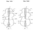
- Figs. 9(A) and 9(B) are plan views showing modifications of the first embodiment, in each of which the napkin body 2 is flattened.
- the bonding region is divided into three regions, in the order from front to rear, a first bonding region 133a, a second bonding region 133b, and a third bonding region 133c.
- the first bonding region 133a extends rearward from the front edge 4 of the sanitary napkin 1, while the third bonding region 133c extends forward from the rear edge 5.
- the first bonding region 133a has the same adhesive application width W1 as the first bonding region 33a shown in Fig. 2.
- the third bonding region 133c has the same adhesive application width W5 as the fifth bonding region 33e shown in Fig. 2.
- the adhesive application width gradually and continuously decreases toward a location midway between the first bonding region 133a and the third bonding region 133c.
- the location where the width is minimized is indicated by 133d.
- the location 133d corresponds to the location (d) shown in Fig. 2 and has the same adhesive application width W3 as the third bonding region 33c shown in Fig. 3.
- the cross section of the projection 41 varies continuously.
- the width gradually decreases and the height gradually increases rearward from the first bonding region 133a.
- the width is minimized and the height is maximized at the location 133d.
- Behind the location 133d the width gradually increases and the height gradually decreases.
- the projection 41 is intended to face the deepest part of the intergluteal cleft at the location 133d.
- the body surface of the napkin body 2 has the first bonding region 33a, the second bonding region 33b, the fourth bonding region 33d, and the fifth bonding region 33e, as in Fig. 2. Between the second bonding region 33b and the fourth bonding region 33d, however, there is provided an unbonding region 33f where no adhesive is applied.
- the unbonding region 33f extends the same length as the third bonding region 33c shown in Fig. 2.
- the surface element 3 which is secured on the body surface of the napkin body 2 through the adhesive applied as shown in Fig. 9(B), forms the same flat portions 42, 43 and the same projection 41 as in the first embodiment.
- the projection 41 which is high and narrow as shown in Fig. 6, is allowed to move freely on the napkin body 2. Therefore, even if the undergarment is deformed due to movement of the wearer's body and the napkin body 2 is moved laterally, a fit of the projection 41 in the intergluteal cleft can easily be maintained.
- the bonding region is divided into the five regions.
- the second bonding region 33b, the third bonding region 33c, and the fourth bonding region 33d may have an equal adhesive application width, if desired.
- the means for securing the surface element 3 on the napkin body 2 is not limited to the hot-melt type adhesive.
- the surface element 3 may be fusion-bonded to the napkin body 2.
- the lateral distance between the base ends of the projection 41 may vary in the same manner as the adhesive application width varies in the foregoing embodiments.
- Fig. 10 is a sectional view showing another modification of the first embodiment and corresponding to the sectional view of Fig. 6.
- Fig. 10 shows a sanitary napkin 101 comprising a napkin body 102 and a projection 141.
- the napkin body 102 is covered with a topsheet 123, which is a laminate of first and second liquid-permeable sheet 123a, 123b.
- the topsheet 123 is bonded to the body surface of the liquid-absorbent layer 22 outside base ends 144, 144 of the projection 141 and to the backsheet 21 outside the side edges 22c, 22c of the liquid-absorbent layer 22.
- the topsheet 123 is raised from the body surface of the liquid-absorbent layer 22 to form the projection 141.
- a surface element 103 is formed of a part of the topsheet 123.
- the lateral distance between the base ends 144, 144 may vary with location in the same manner as the adhesive application width varies in Fig. 2, 9(A), or 9(B).
- the central elastic member 34 is contained in an apex 141a of the projection 141. If desired, the side elastic members 35 may be provided in the projection 141 shown in Fig. 10.
- the width and height of the projection 141 may vary in a similar way to the first embodiment shown in Fig. 2 and its modifications shown in Figs. 9(A) and 9(B). Moreover, since the liquid-absorbent layer 22 is located beneath the projection 141, menstrual blood after passing through the projection 141 can be quickly absorbed by the liquid-absorbent layer 22.
- Fig. 11(A) is a perspective view showing a sanitary napkin 201 according to a second embodiment of the present invention
- Fig. 11(B) is a side view of the sanitary napkin 201
- Fig. 12 is a sectional view taken along line XII-XII of Fig. 11(A)
- Fig. 13 is a sectional view taken along line XIII-XIII of Fig. 11(A).
- the sanitary napkin 201 comprises a napkin body 202 and a projection 241 formed of a surface element 203.
- the napkin body 202 according to the second embodiment has the same construction as the napkin body 2 according to the first embodiment, except that the fold-back flaps 7, 7 are not provided in the napkin body 202.
- the surface element 203 includes a liquid-permeable sheet and the central elastic member 34 extending along the longitudinal centerline. Between the front end 34c and the front connection point 34a, the central elastic member 34 is secured on the body surface of the napkin body 202. Behind the front connection point 34a, on the other hand, the central elastic member 34 is separated from the napkin body 202.
- the bonding width between the surface element 203 and the napkin body 202 gradually decreases rearward, as shown in Figs. 12 and 13.
- the surface element 203 has a reinforcing member 205 at its rear end 203a.
- the reinforcing member 205 is raised from the napkin body 202.
- the rear end 203a of the surface element 203 and the rear end 34d of the central elastic member 34 are bonded to the reinforcing member 205.
- the reinforcing member 205 is preferably hydrophilic and may be made of a material which can be freely deformed when subjected to the weight of a wearer, such as an air-laid pulp, in which pulp (and optionally hydrophilic fibers such as rayon) are compressed and fixed through a binder, a compressed pulp, or a hydrophilic resin foam sheet.
- a material which can be freely deformed when subjected to the weight of a wearer such as an air-laid pulp, in which pulp (and optionally hydrophilic fibers such as rayon) are compressed and fixed through a binder, a compressed pulp, or a hydrophilic resin foam sheet.
- the laterally spaced base ends of the projection 241 are indicated by 244a in Fig. 12 and by 244b in Fig. 13.
- the lateral distance between base ends 244a, 244a is large, while the height of an apex 241a, which is raised by an elastic tension of the central elastic member 34, is small.
- the lateral distance between base ends 244b, 244b is small, while the rising height of the apex 241a is large.
- the front portion of the projection 241 is wide and low as shown in Fig. 12, it can easily fit on the vagina and its vicinity; since the rear portion of the projection 241 is narrow and high as shown in Fig. 13, it can easily fit in the intergluteal cleft behind the anus.
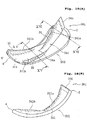
- Fig. 14(A) is a perspective view showing a sanitary napkin 301 according to a third embodiment of the present invention
- Fig. 14(B) is a side view of the sanitary napkin 301
- Fig. 15 is a sectional view taken along line XV-XV of Fig. 14(A)
- Fig. 16 is a sectional view taken along line XVI-XVI of Fig. 14(A).
- the sanitary napkin 301 has a surface element 303 on the napkin body 202 that is the same as that of the second embodiment. In its rear portion, the surface element 303 has the same construction as the surface element 203. Thus, the surface element 303 has the reinforcing member 205 which is raised from the napkin body 202 and the central elastic member 34 which is separated from the napkin body 202 and adapted to exert a longitudinal elastic tension between the front connection point 34a and the reinforcing member 205.
- the side elastic members 35, 35 are provided to extend longitudinally near the side edges of the napkin body 202.
- the side elastic members 35, 35 are bonded to the liquid-permeable sheet of the surface element 303 with their front and rear ends secured on the napkin body 2, so that their intermediate portions under an elastic tension are raised from the napkin body 202.
- the front portion of the surface element 303 is widely bonded to the napkin body 202, as shown in Fig. 15.
- the bonding width gradually decreases rearward.
- the surface element 303 forms a projection 341 with three apexes: one central apex 341a and two side apexes 341b, 341b.
- the laterally spaced base ends of the projection 341 are indicated by 344a in Fig. 15 and by 344b in Fig. 16.
- the lateral distance between the base ends 344a, 344a is large with the side apexes 341b, 341b extending longitudinally outside the base ends 344a, 344a.
- the lateral distance between the base ends 344b, 344b is small with the central apex 341a being raised high from the body surface of the napkin body 202 under an elastic tension of the central elastic member 34.
- the front portion of the projection 341 is wide and low as shown in Fig. 15, it can easily fit on the vagina and its vicinity; since the rear portion of the projection 341 is narrow and high as shown in Fig. 16, it can easily fit in the intergluteal cleft.
- Fig. 17 is a perspective view showing a sanitary napkin 401 according to a fourth embodiment of the present invention in a natural state where no external force is exerted thereon
- Fig. 18 is a sectional view take along line XVIII-XVIII of Fig. 17
- Fig. 19 is a sectional view take along line XIX-XIX of Fig. 17.
- the sanitary napkin 401 has a surface element 403 on the napkin body 2 that is the same as that of the first embodiment.
- the surface element 403 is formed of the liquid-permeable sheet 31 that is a laminate of the first and second liquid-permeable sheets 31a, 31b, as in the first embodiment.
- the bonding width between the surface element 403 and the napkin body 2 is large in front and rear ends of the sanitary napkin 401 and gradually decreases toward a location midway between the front and rear ends.
- the bonding width is minimized at a location which corresponds to the location (d) shown in Fig. 2.
- elastic members 434, 435 are bonded while being stretched at least 1.2 times, preferably at least 1.5 times the original length.
- the elastic member 434 is raised from the napkin body 2 between front and rear connection points 434a, 434b.
- the elastic member 435 is also raised from the napkin body 2 between front and rear connection points 435a, 435b.
- the front connection point 434a of the elastic member 434 and the front connection point 435a of the elastic member 435 are laterally spaced from each other.
- the elastic members 434, 435 approach each other as they extend rearward and cross each other at the location corresponding to the location (d) shown in Fig. 2.
- the rear connection point 434b of the elastic member 434 and the rear connection point 435b of the elastic member 435 are laterally spaced from each other in the rear part of the napkin body 2.
- the napkin body 2 is curved under an elastic tension exerted by the elastic members 434, 435. Between the front connection points 434a, 435a and the rear connection points 434b, 435b, therefore, the liquid-permeable sheet 31 is raised from the napkin body 2 to form a projection 441.
- the laterally spaced base ends of the projection 441 are indicated by 444a in Fig. 18 and by 444b in Fig. 19.
- the height of the projection 441 is small.
- the projection 441 has almost the same cross section as in Fig. 18.
- the projection 441 has a generally triangular cross section at the location corresponding to the location (d).
- the front and rear portions of the projection 441 are wide and low as in the first embodiment, it can easily fit on the vagina and its vicinity and the coccyx and its vicinity; since the intermediate portion of the projection 441, which is intended to face the intergluteal cleft, is narrow and high and has an acute apex as shown in Fig. 19, it can easily fit in the intergluteal cleft.
- Fig. 20 is a perspective view showing a sanitary napkin 501 according to a fifth embodiment of the present invention in a natural state where no external force is exerted thereon
- Fig. 21 is a sectional view taken along line XXI-XXI of Fig. 20
- Fig. 22 is a sectional view taken along line XXII-XXII of Fig. 20
- Fig. 23 is a sectional view taken along line XXIII-XXIII of Fig. 20.
- the sanitary napkin 501 has a surface element 503 on the napkin body 2 that is the same as that of the first embodiment.
- the surface element 503 is formed of the liquid-permeable sheet 31 that is a laminate of the first and second liquid-permeable sheets 31a, 31b, as in the first embodiment.
- the liquid-permeable sheet 31 may be a singe through-air bonded nonwoven fabric.
- the surface element 503 has the central elastic member 33 on the longitudinal centerline and the side elastic members 35, 35 on laterally opposite sides of the longitudinal centerline. As shown in Fig. 20, the front connection point 34a of the central elastic member 34 and the front connection points 35a, 35a of the side elastic members 35, 35 are located slightly forward of the fold-back flaps 7, 7.
- the rear connection point 34b of the central elastic member 34 is located adjacent the rear edge 5, and the rear connection points 35b, 35b of the side elastic members 35, 35 are located slightly forward of the rear connection point 34b of the central elastic member 34.
- the liquid-permeable sheet 31 of the surface element 503 is folded flat to form a front flat portion 542, which is secured on the body surface of the napkin body 2. Also behind the rear connection point 34b of the central elastic member 34, the liquid-permeable sheet 31 is folded flat to form a rear flat portion 543, as shown in Fig. 20.
- the surface element 503 forms a projection 541.
- the bonding width between the surface element 503 and the napkin body 2 is enlarged to house a hydrophilic material 522 in the surface element 503, as shown in Fig. 22.
- the hydrophilic material 522 may be made of a material capable of absorbing liquid by itself and transferring the liquid to the liquid-absorbent layer 22 of the napkin body 2, such as an air-laid pulp, another pulp layer, or a laminate of hydrophilic nonwoven fabrics or papers.
- a cushion material may be housed in place of the hydrophilic material 522.
- the cushion material is a resilient, low-density material which allows liquid such as menstrual blood to descend and transfer to the liquid-absorbent layer 22 under force of gravity, such as a through-air bonded nonwoven fabric.
- the laterally spaced base ends of the projection 541 are indicated by 544a in Fig. 22 and by 544b in Fig. 23.
- the lateral distance between the base ends 544a, 544a is large and the height of the projection 541 is small.
- the projection 541 is intended to face the vagina and its vicinity at the portion containing the hydrophilic material or cushion material 522.
- the surface element 503 is hollow, and the bonding width between the surface element 503 and the napkin body 2 is smaller than in Fig. 22. Therefore, as shown in Fig. 23, the lateral distance between the base ends 544b, 544b is small, and an apex 541a of the projection 541 is raised high from the napkin body 2 under an elastic tension exerted by the central elastic member 34.
- the projection 541 can fit on the vagina and its vicinity at the wide and low portion containing the hydrophilic material or cushion material 522. This portion feels soft to the touch due to the presence of the hydrophilic material or cushion material 522. On the other hand, the projection 541 can easily fit in the intergluteal cleft at the narrow, elongated, hollow portion shown in Fig. 23.
- Fig. 24 is a perspective view showing a sanitary napkin 601 according to a sixth embodiment of the present invention in a natural state where no external force is exerted thereon
- Fig. 25 is a sectional view taken along line XXV-XXV of Fig. 24
- Fig. 26 is a sectional view taken along line XXVI-XXVI of Fig. 24.
- the sanitary napkin 601 comprises a napkin body 602 and a projection 641 formed of a surface element 603.
- the napkin body 602 has the backsheet 21, the liquid-absorbent layer 22, and a topsheet 623.
- the topsheet 623 is bonded to the body surface of the liquid-absorbent layer 22.
- the topsheet 623 is bonded to the side edges 22c, 22c of the liquid-absorbent layer 22 and to the backsheet 21 outside the side edges 22c, 22c, but remains unbonded to the body surface of the liquid-absorbent layer 22.
- the topsheet 623 is allowed to move away from the body surface of the liquid-absorbent layer 22.
- the side elastic members 35, 35 are disposed to extend a given length in the longitudinal direction, as shown in Fig. 25.
- the side elastic members 35, 35 which are laterally spaced from each other, are adapted to exert a longitudinal elastic contractive force between front and rear connection points to move away from the body surface of the liquid-absorbent layer 22.
- the projection 641 has side apexes 641b, 641b along the side elastic members 35, 35.
- the central elastic member 34 is disposed to extend on the longitudinal centerline.
- the side elastic members 35, 35 lie on laterally opposite sides of a front part of the central elastic member 34.
- the central elastic member 34 is adapted to exert a longitudinal elastic contractive force between front and rear connection points to move away from the body surface of the liquid-absorbent layer 22.
- the projection 641 has a central apex 641a along the central elastic member 34.
- a reinforcing sheet 605 is disposed on the garment surface of the topsheet 623 to cover both the central elastic member 34 and the side elastic members 35.
- the reinforcing sheet 605 may be stiff and made of a hydrophilic or liquid-permeable material, such as an air-laid pulp, an apertured resin film, a paper material, or a through-air bonded nonwoven fabric.
- the topsheet 623 can easily be kept flat between the side apexes 641b, 641b in the front part of the sanitary napkin 601, as shown in Fig. 25.
- two slopes on both sides of the central apex 641a can easily be kept flat, as shown in Fig. 26.
- laterally spaced base ends 644, 644 of the projection 641 are located on the side edges 22c, 22c of the liquid-absorbent layer 22.
- the lateral distance between the base ends 644, 644 does not vary at all.
- the projection 641 is wide and low at the portion having the side elastic members 35, 35, as shown in Fig. 25, it can easily fit on the vagina and its vicinity.
- the apex 641a of the projection 641 is raised high and makes an angle behind the fold-back flaps 7, 7, as shown in Fig. 26, it can easily fit in the intergluteal cleft behind the anus.
- the projection is provided with at least one elastic member, such as an elastic filament, so as to raise the liquid-permeable sheet of the surface element from the body surface of the napkin body.
- the elastic member is not limited to such an elastic filament.
- the elastic member may be in the form of a strip.
- the liquid-permeable sheet of the surface element itself may be adapted to exert an elastic contractive force, without providing the foregoing central and side elastic members.
- the liquid-permeable sheet may be a stretchable nonwoven fabric or a nonwoven fabric containing elastic filaments.
Landscapes
- Health & Medical Sciences (AREA)
- Epidemiology (AREA)
- Engineering & Computer Science (AREA)
- Biomedical Technology (AREA)
- Heart & Thoracic Surgery (AREA)
- Vascular Medicine (AREA)
- Life Sciences & Earth Sciences (AREA)
- Animal Behavior & Ethology (AREA)
- General Health & Medical Sciences (AREA)
- Public Health (AREA)
- Veterinary Medicine (AREA)
- Physics & Mathematics (AREA)
- Fluid Mechanics (AREA)
- Absorbent Articles And Supports Therefor (AREA)
- Orthopedics, Nursing, And Contraception (AREA)
Abstract
Description
- The present invention relates to a sanitary napkin with a projection disposed on a body surface of a napkin body and more particularly to a sanitary napkin whose projection can easily conform to the contours of the woman's body so as to be effective in preventing leakage of menstrual blood.
- There have been known sanitary napkins with a napkin body containing a liquid-absorbent layer and a projection projecting from a body surface of the napkin body.
-
Japanese Unexamined Patent Application Publication No. H11-513921 -
Japanese Unexamined Patent Application Publication No. H09-313529 -
Japanese Unexamined Patent Application Publication No. 2002-320638 -
Japanese Unexamined Patent Application Publication No. 2001-504727 - In all these conventional sanitary napkins, a projection designed to fit against the wearer's body is disposed on the body surface of the napkin body so as to prevent leakage of liquid such as menstrual blood.
- In the woman's crotch, however, the cleft varies in shape anteroposteriorly to have different opening widths and depths for different regions. Around the vaginal opening and the labia majora, the cleft has a relatively large opening width. Near and behind the anus, the cleft lies between the buttocks. The cleft between the buttocks (or the intergluteal cleft) becomes the deepest behind the anus and then shallower toward the coccyx.
- In order that the liquid-absorbent layer of the sanitary napkin can effectively absorb liquid such as menstrual blood discharged from the vaginal opening, moreover, the sanitary napkin is required to reliably fit on the vaginal opening and its vicinity.
- In the sanitary napkins disclosed in the Patent Publication
Nos. H11-513921 H09-313529 2002-320638 , however, the projection is uniform in width and does not change much in height over the length of the projection. Therefore, the projection, which is not in conformity with the contours of the woman's crotch, may cause a problem of failing to snugly fit on the vaginal opening or to reliably find its way into the intergluteal cleft. - In the sanitary napkin disclosed in the Patent Publication
No. 2001-504727 , on the other hand, both the width and the height become the largest centrally of the projection. When the center of the projection is applied to the vaginal opening and its vicinity, the projection tends to make a wearer feel uncomfortable because it is too high. When the center of the projection is applied to the intergluteal cleft, the projection cannot easily find its way into the intergluteal cleft because it is too wide. When the center of the projection is applied to the coccyx and its vicinity, the projection tends to create a gap between the napkin body and the buttocks because it is too high. - The present invention has been developed to solve the problems in the prior art set forth above and has an object to provide a sanitary napkin in which a projection varies in width and height in accordance with the physical features of a woman so as to improve conformity with the body of a woman.
- According to a first aspect of the present invention, there is provided a sanitary napkin comprising:
- a napkin body having a liquid-absorbent layer for absorbing and retaining liquid; and
- a projection projecting from a body surface of the napkin body,
- In this construction, accordingly, the projection is relatively low at a portion where the width of the projection is relatively large and relatively high at a location where the width of the projection is relatively small. The relatively high, narrow portion can easily fit in a deep portion of the intergluteal cleft; the relatively low, wide portion can easily fit on the vaginal opening and its vicinity, in a rear shallow portion of the intergluteal cleft, or on the coccyx and its vicinity.
- Preferably, the distance between the base ends is larger in a front portion of the projection than in a rear portion behind the front portion. In this construction, the front portion of the projection can easily fit on the vaginal opening and its vicinity, and the rear portion can easily fit in a deep portion of the intergluteal cleft.
- Also preferably, the distance between the base ends is larger in front and rear portions of the projection than in an intermediate portion between the front and rear portions. In this construction, the front portion of the projection can easily fit on the vaginal opening and its vicinity, the intermediate portion of the projection can easily fit in a deep portion of the intergluteal cleft, and the rear portion of the projection can easily fit in a rear shallow portion of the intergluteal cleft or on the coccyx and its vicinity.
- Here, the distance between the base ends may vary stepwise or continuously.
- According to a second aspect of the present invention, there is provided a sanitary napkin comprising:
- a napkin body having a liquid-absorbent layer for absorbing and retaining liquid; and
- a projection projecting from a body surface of the napkin body,
- In this construction, the second portion can deform independently of the napkin body. Accordingly, when the second portion is located in the intergluteal cleft, a fit of the projection in the intergluteal cleft can easily be maintained even if the napkin body moves laterally.
- Preferably, the first portion is located forward of the second portion.
- In both the first and second aspects of the present invention, the projection may be adapted to exert a longitudinal elastic contractive force to draw front and rear ends of the napkin body closer to each other and concavely curve the body surface of the napkin body, so that the projection can be raised from the body surface of the napkin body.
- According to a third aspect of the present invention, there is provided a sanitary napkin comprising:
- a napkin body having a liquid-absorbent layer for absorbing and retaining liquid; and
- a projection projecting from a body surface of the napkin body with elastic members adapted to exert a longitudinal elastic contractive force for rising of the projection,
- In this construction, the projection is relatively low at a location
where the distance between the elastic members is relatively large and relatively high at a location where the distance between the elastic members is relatively small. - According to one embodiment, the elastic members may be laterally spaced from each other in a front portion of the projection, but cross each other in a rear portion behind the front portion.
- According to a fourth aspect of the present invention, there is provided a sanitary napkin comprising:
- a napkin body having a liquid-absorbent layer for absorbing and retaining liquid; and
- a projection projecting from a body surface of the napkin body with elastic members adapted to exert a longitudinal elastic contractive force for rising of the projection,
- Here, the elastic member of the second portion is not necessarily required to lie right on the longitudinal centerline. For instance, the elastic member may be spaced from the longitudinal centerline or two or more elastic members may be arranged at a small distance on both sides of the longitudinal centerline. These elastic members may be parallel to each other.
- In both the third and fourth aspects of the present invention, the body surface of the napkin body may be concavely curved with front and rear ends of the napkin body drawn closer to each other by the elastic contractive force of the elastic members.
- In the first to fourth aspects of the present invention, the projection may be formed separately from the napkin body and then secured on the body surface of the napkin body. Alternatively, the napkin body may include a topsheet covering the liquid-absorbent layer, and the protrusion may be formed by a part of the topsheet.
- According to the present invention, the projection can easily conform to the contours of the woman's body. Thus, lateral leakage or rearward leakage of liquid such as menstrual blood can be effectively prevented.
- The present invention will be understood more fully from the detailed description given hereinafter and from the accompanying drawings of the preferred embodiment of the present invention, which, however, should not be taken to limit the invention, but are for explanation and understanding only.
- In the drawings:
- Fig. 1 is a perspective view of a sanitary napkin according to a first embodiment of the present invention in a natural state where no external force is exerted thereon,
- Fig. 2 is a plan view showing a body surface of a flattened napkin body according to the first embodiment,
- Fig. 3 is a sectional view taken along line III-III of Fig. 1,
- Fig. 4 is a sectional view taken along line IV-IV of Fig. 1,
- Fig. 5 is a sectional view taken along line V-V of Fig. 1,
- Fig. 6 is a sectional view taken along line VI-VI of Fig. 1,
- Fig. 7 is a longitudinal sectional view schematically showing a state where a sanitary napkin is applied to the woman's body,
- Fig. 8 is a view schematically showing a method for measuring a height and a repulsive force of a projection of a sanitary napkin,
- Figs. 9(A) and 9(B) are plan views showing napkin bodies of modifications of the first embodiment,
- Fig. 10 is a sectional view showing another modification of the first embodiment,
- Fig. 11(A) is a perspective view of a sanitary napkin according to a second embodiment of the present invention in a natural state where no external force is exerted thereon, and Fig. 11(B) is a side view thereof,
- Fig. 12 is a sectional view take along line XII-XII of Fig. 11(A),
- Fig. 13 is a sectional view take along line XIII-XIII of Fig. 11(A),
- Fig. 14(A) is a perspective view of a sanitary napkin according to a third embodiment of the present invention in a natural state where no external force is exerted thereon, and Fig. 14(B) is a side view thereof,
- Fig. 15 is a sectional view take along line XV-XV of Fig. 14(A),
- Fig. 16 is a sectional view take along line XVI-XVI of Fig. 14(A),
- Fig. 17 is a perspective view of a sanitary napkin according to a fourth embodiment of the present invention in a natural state where no external force is exerted thereon,
- Fig. 18 is a sectional view take along line XVIII-XVIII of Fig. 17,
- Fig. 19 is a sectional view take along line XIX-XIX of Fig. 17,
- Fig. 20 is a perspective view of a sanitary napkin according to a fifth embodiment of the present invention in a natural state where no external force is exerted thereon,
- Fig. 21 is a sectional view take along line XXI-XXI of Fig. 20,
- Fig. 22 is a sectional view take along line XXII-XXII of Fig. 20,
- Fig. 23 is a sectional view take along line XXIII-XXIII of Fig. 20,
- Fig. 24 is a perspective view of a sanitary napkin according to a sixth embodiment of the present invention in a natural state where no external force is exerted thereon,
- Fig. 25 is a sectional view take along line XXV-XXV of Fig. 24, and
- Fig. 26 is a sectional view take along line XXVI-XXVI of Fig. 24.
- The present invention will be discussed hereinafter in detail in terms of the preferred embodiment according to the present invention with reference to the accompanying drawings. In the following description, numerous specific details are set forth in order to provide a thorough understanding of the present invention. It will be obvious, however, to those skilled in the art that the present invention may be practiced without these specific details. In other instance, well-known structures are not shown in detail in order to avoid unnecessary obscuring of the present invention.
- Fig. 1 is a perspective view of a
sanitary napkin 1 according to a first embodiment of the present invention in a natural state where no external force is exerted thereon. Fig. 2 is a plan view in which a surface element is removed from thesanitary napkin 1 and only a napkin body is flattened. Fig. 3 is a sectional view taken along line III-III of Fig. 1, Fig. 4 is a sectional view taken along line IV-IV of Fig. 1, Fig. 5 is a sectional view taken along line V-V of Fig. 1, and Fig. 6 is a sectional view taken along line VI-VI of Fig. 1. Fig. 7 is a longitudinal sectional view schematically showing a state where thesanitary napkin 1 is applied to the woman's body from the crotch to the buttocks. - It should be noted that the sanitary napkin, as well as its individual components, has two major surfaces: of which one surface intended to be worn toward the wearer's crotch is referred to as "body surface", while the other surface is referred to as "garment surface". In addition, the lengthwise direction of the sanitary napkin is referred to as "longitudinal direction", while the direction perpendicular to the longitudinal direction is referred to as "lateral direction". With respect to dimensions of the individual components, unless otherwise stated, a dimension measured in the longitudinal direction is referred to as "length", while a dimension measured in the lateral direction is referred to as "width".
- In Fig. 1, several locations, which are spaced apart from each other in the longitudinal direction of the
sanitary napkin 1, are indicated by (a) to (g). Also in Fig. 2, the corresponding locations are indicated by (a) to (g). - The
sanitary napkin 1 comprises anapkin body 2 and asurface element 3 disposed on the body surface of thenapkin body 2 to form a projection. - As shown in Figs. 3 to 6, the
napkin body 2 includes a liquid-blockingbacksheet 21 on the garment surface side of thenapkin body 2, a liquid-absorbent layer 22 disposed on thebacksheet 21, and a liquid-permeable topsheet 23 covering the liquid-absorbent layer 22. - As shown in Fig. 2, the
napkin body 2 has arcuate front andrear edges napkin body 2 is elongated to have a length L1 in the range of 280 to 450 mm. The liquid-absorbent layer 22 is also elongated to have arcuate front andrear edges rear edges absorbent layer 22 has right and leftside edges side edges absorbent layer 22 should not be understood as limited to this embodiment. - On laterally opposite sides of the liquid-
absorbent layer 22, thenapkin body 2 has laterally projectingfront flaps back flaps rear flaps front flaps back flaps rear flaps backsheet 21 is covered with a liquid-blockingside sheet 24. The liquid-blockingside sheet 24 is bonded to thebacksheet 21 through a hot-melt type adhesive. - As shown in Figs. 3 to 6, the
side sheets edges absorbent layer 22, therefore, the body surface of the liquid-absorbent layer 22 is covered with thetopsheet 23, and the body surface of thetopsheet 23 is further covered with theside sheets edges side sheets permeable topsheet 23 is exposed externally. The overlap between this area and the liquid-absorbent layer 22 is called "main liquid-absorbent region." - X1 shown in Fig. 2 represents a vagina-facing reference line, and this vagina-facing reference line X1 is spaced 100 to 200 mm, preferably 100 to 140 mm, for example, about 120 mm, rearward from the
front edge 4 of thenapkin body 2. - The vagina-facing reference line X1 as used herein is a target position with which the center of the vaginal opening is to almost coincide when wearing the
sanitary napkin 1 along with an undergarment. Leading to this target is through the contour of the sanitary napkin as viewed from the body surface side or the whole design including the arrangement of compression lines on the body surface. Particularly when the fold-back flaps back flaps back flaps - X2 shown in Fig. 2 represents an anus-facing reference line, and this anus-facing reference line X2 is intended to face the anus when the vagina-facing reference line X1 coincides with the center of the vaginal opening. The anus-facing reference line X2 is usually spaced a distance L2 of 30 to 70 mm, which varies depending on the wearer's body, rearward from the vagina-facing reference line X1.
- X3 shown in Fig. 2 represents a coccyx-facing reference line. This coccyx-facing reference line X3 is intended to face the coccyx when the vagina-facing reference line X1 coincides with the center of the vaginal opening. The coccyx-facing reference line X3 is usually spaced a distance L3 of 120 to 180 mm, which varies depending on the wearer's body, rearward from the vagina-facing reference line X1. For example, the coccyx-facing reference line X3 may be spaced 175 mm rearward from the vagina-facing reference line X1. The
rear edge 5 of thenapkin body 2 and therear edge 22b of the liquid-absorbent layer 22 are located behind the coccyx-facing reference line X3. - Between the vagina-facing reference line X1 and the coccyx-facing reference line X3, the
napkin body 2 is intended to face the vaginal opening, the anus, and the intergluteal cleft. Throughout the disclosure, the cleft extending from forward of the vaginal opening to adjacent the coccyx in the woman's body is merely called "cleft", while the cleft extending from the anus to the coccyx is called "intergluteal cleft". - The
backsheet 21 may be a film, for example, a polyethylene resin film having a basis weight of about 23.5 g/m2, and is preferably permeable to moisture. The liquid-absorbent layer 22 may be a mixture of fluff pulp and superabsorbent polymer (SAP) wrapped in a hydrophilic tissue having a basis weight of 18 g/m2. The fluff pulp may have a weight of about 400 g/m2; the SAP may have a weight of about 12 g/m2. Theside sheet 24 may be a spunbonded nonwoven fabric made of polyethylene/polypropylene sheath/core bicomponent fibers. The spunbonded nonwoven fabric may have a basis weight of about 22 g/m2. - The
topsheet 23 may be a through-air bonded nonwoven fabric having a basis weight of about 25 g/m2. The through-air bonded nonwoven fabric may be made of polyethylene/polyethylene terephthalate sheath/core bicomponent fibers with an inorganic filler such as titanium oxide mixed into the core of polyethylene terephthalate. - The
surface element 3 may have a hydrophilic, liquid-permeable sheet 31. The liquid-permeable sheet 31 may be a laminate of first and second liquid-permeable sheets permeable sheet 31a is an outermost layer, while the second liquid-permeable sheet 31b is located inside the first liquid-permeable sheet 31a. In order not to interfere with liquid passage, the first and second liquid-permeable sheets permeable sheets - The first and second liquid-
permeable sheets - The first and second liquid-
permeable sheets - Alternatively, the first and second liquid-
permeable sheets permeable sheet 31a, while the nonwoven fabric such as through-air bonded may be used as the second liquid-permeable sheet 31b. The liquid-permeable sheet 31 may be embossed in a dot pattern or corrugated. It is, of course, possible that the liquid-permeable sheet 31 is a single nonwoven fabric. - As shown in Figs. 3 to 6, the opposite edges of the liquid-
permeable sheet 31 are bonded to each other to have a bond 32. This bonding may be adhesive-bonding through a hot-melt type adhesive or fusion-bonding. The bond 32 is located to face thetopsheet 23 of thenapkin body 2 and extends along the longitudinal centerline Oy. - In the first embodiment, the
surface element 3 is bonded to the body surface of thenapkin body 2 through a hot-melt type adhesive. - In Fig. 2, the bonding region where the
surface element 3 is bonded to the body surface of thenapkin body 2 is indicated by hatching for the sake of convenience. In the bonding region, the hot-melt type adhesive may be applied in such a manner as not to interfere with passage of liquid through thetopsheet 23. For example, the hot-melt type adhesive may be applied in a spiral pattern, a dot pattern, or a striped pattern or sprayed in an emulsion state. - As shown in Fig. 2, the bonding region may be divided into five regions, in the order from front to rear, a
first bonding region 33a, asecond bonding region 33b, athird bonding region 33c, afourth bonding region 33d, and afifth bonding region 33e. Thefirst bonding region 33a extends rearward from thefront edge 4 of thesanitary napkin 1, while thefifth bonding region 33e extends forward from therear edge 5 of thesanitary napkin 1. - In the
first bonding region 33a, the adhesive is applied in the shape of a strip which extends longitudinally with a uniform width. The adhesive application width of thefirst bonding region 33a is indicated by W1. Also in the second tofifth bonding regions 33b to 33e, the adhesive is applied in the shape of a strip which extends longitudinally with a uniform width. The adhesive application width of thesecond bonding region 33b is indicated by W2, the adhesive application width of thethird bonding region 33c is indicated by W3, the adhesive application width of thefourth bonding region 33d is indicated by W4, and the adhesive application width of thefifth bonding region 33e is indicated by W5. - The adhesive application width may vary stepwise such that W1 > W2 > W3 and W3 < W4 < W5. Although W1 is equal to W5 and W2 is equal to W4 in the embodiment shown in Fig. 2, W1 may be different from W5 and W2 may be different from W4. For example, W1 and W5 may be 28 mm, W2 and W4 may be 18 mm, and W3 may be 6 mm. The difference between W1 and W2, the difference between W2 and W3, the difference between W5 and W4, and the difference between W4 and W3 are preferably 5 mm or more, or each difference is preferably 10% or more of the larger one. The difference between W1 and W3 and the difference between W5 and W3 are preferably 10 mm or more, or W3 is preferably 80% or less, more preferably 60% or less, of W1 and W5.
- In the first embodiment shown in Figs. 1 to 6, the
individual bonding regions 33a-33e are symmetrical about the longitudinal centerline Oy. - As shown Fig. 2, the boundary between the first and
second bonding regions surface element 3 forms aprojection 41 which is low and wide near the vagina-facing reference line X1. Theprojection 41 increases in height and decreases in width rearward from the vagina-facing reference line X1. - The boundary between the second and
third bonding regions projection 41 reaches a maximum height and a minimum width behind the anus-facing reference line X2. This highest portion is intended to face the intergluteal cleft. - The front end of the
third bonding region 33c is preferably spaced 30 to 180 mm rearward from the vagina-facing reference line X1. The length of thethird bonding region 33c is preferably 30 mm or more. - As shown in Figs. 3 to 6, the
surface element 3 has a centralelastic member 34 between the first and second liquid-permeable sheets elastic member 34 extends on the longitudinal centerline Oy in Fig. 2. The centralelastic member 34 may be bonded to the first and second liquid-permeable sheets - As shown in Fig. 1, the central
elastic member 34 has afront end 34c at thefront edge 4 of thesanitary napkin 1. Between thefront end 34c and a front connection point (or front footpoint) 34a behind thefront end 34c, the centralelastic member 34, as well as the liquid-permeable sheet 31, is secured on the body surface of thenapkin body 2. The centralelastic member 34 has arear end 34d at therear edge 5 of thesanitary napkin 1. Between therear end 34d and a rear connection point (or rear footpoint) 34b forward of therear end 34d, the centralelastic member 34, as well as the liquid-permeable sheet 31, is secured on the body surface of thenapkin body 2. - It should be noted that the central
elastic member 34 is bonded to the liquid-permeable sheet 31 between the front andrear connection points front connection point 34a and behind therear connection point 34b, on the other hand, the centralelastic member 34 does not have to be bonded to the liquid-permeable sheet 31. Sideelastic members 35, which will be described in detail below, may be bonded to the liquid-permeable sheet 31 in the same manner as described above. - Fig. 3 shows the cross section at the location indicated by (a) in Figs. 1 and 2. At the location (a), as described above, the central
elastic member 34 is secured on the body surface of thenapkin body 2, while the liquid-permeable sheet 31 is folded flat on the body surface of thenapkin body 2. In this folded state, the sideelastic members elastic members permeable sheets surface element 3 is folded flat, as shown in Fig. 3, the sideelastic members elastic member 34 with an equal distance laterally from the centralelastic member 34. - The side
elastic member 35 has afront end 35c at thefront edge 4 of thesanitary napkin 1. Between thefront end 35c and afront connection point 35a behind thefront end 35c, the sideelastic member 35 is secured on the body surface of thenapkin body 2. The sideelastic member 35 also has arear end 35d at therear edge 5 of thesanitary napkin 1. Between therear end 35d and arear connection point 35b forward of therear end 35d, the sideelastic member 35 is secured on the body surface of thenapkin body 2. - The
front connection points 35a of the sideelastic members 35 are located behind thefront connection point 34a of the centralelastic member 34 and on the boundary between the first andsecond bonding regions elastic members 35 are located forward of therear connection point 34b of the centralelastic member 34 and on the boundary between the fourth andfifth bonding regions - However, if desired, the
front connection point 34a of the centralelastic member 34 may be located on the same straight line as thefront connection points 35a of the sideelastic members 35, and therear connection point 34b of the centralelastic member 34 may be located on the same straight line as the rear connection points 35b of the sideelastic members 35. - When no external force is exerted on the
sanitary napkin 1, the centralelastic member 34 exerts an elastic tension between the front andrear connection points rear connection points elastic member 35 exerts an elastic tension between the front andrear connection points rear connection points - As a result, as shown in Fig. 1, the front and rear ends of the
napkin body 2 approach each other to concavely curve the body surface of thenapkin body 2. Here, the centralelastic member 34 moves away from the body surface of thenapkin body 2 between the front andrear connection points elastic member 35 moves away from the body surface of thenapkin body 2 between the front andrear connection points permeable sheet 31 is raised from the body surface of thenapkin body 2 by the raised portions of theelastic members hollow projection 41. In the first embodiment, the front andrear connection points elastic member 34 define front and rear ends of theprojection 41, respectively. - Forward of the
front connection point 34a of the centralelastic member 34, as shown in Fig. 3, the liquid-permeable sheet 31 is secured on the body surface of thenapkin body 2 in the folded state, forming a frontflat portion 42. Behind therear connection point 34b of the centralelastic member 34, the liquid-permeable sheet 31 is also secured on the body surface of thenapkin body 2 in the same folded state as shown in Fig. 3, forming a rear flat portion 43. - The cross section of the
projection 41 varies depending on the adhesive application widths W1 to W5 of the first tofifth bonding regions 33a-33e shown in Fig. 2. - Fig. 4 shows the cross section of the
projection 41 at the location indicated by (b) in Figs. 1 and 2. The location (b) lies on thefirst bonding region 33a and is located behind thefront connection point 34a of the centralelastic member 34 and forward of thefront connection points 35a of the sideelastic members 35. - At the location (b), the side
elastic members napkin body 2, defining base ends 44a, 44a of theprojection 41. On the other hand, the centralelastic member 34 is raised from the body surface of thenapkin body 2. Thus, theprojection 41 provides an apex 41a along the centralelastic member 34. The apex 41a extends on the longitudinal centerline Oy in Fig. 2. - At the location (b), the
projection 41 has inclinedside wall portions permeable sheet 31 to extend from the apex 41a to the respective base ends 44a, 44a. At the location (b), the opening angle between theside wall portions θ 1. - At the location (b), the lateral distance between the base ends 44a, 44a of the
projection 41 is almost equal to the adhesive application width W1 of thefirst bonding region 33a shown in Fig. 2. Thus, theprojection 41 is wide. More specifically, since the adhesive application width W1 is large, the height from the body surface of thenapkin body 2 to the apex 41a is as small as 5 to 30 mm, preferably 5 to 15 mm. Here, theopening angle θ 1 between theside wall portions - According to other embodiments, the
opening angle θ 1 may be 90 degrees or more. In case where the sideelastic members napkin body 2 than the centralelastic member 34, the upper limit of theopening angle θ 1 may be about 270 degrees, preferably 240 degrees or less. - At the location (b), as shown in Fig. 7, the
projection 41 is intended to face the front part of the vagina 51 of the woman'sbody 50. Here, the vagina 51 refers to an area including the labia majora. Since theprojection 41 is wide and low and theopening angle θ 1 is large at the location (b), theprojection 41 can easily fit on the vagina 51 without exerting an excessive pressure or a local pressure thereon. - Fig. 5 shows the cross section of the
projection 41 at the location indicated by (c) in Figs. 1 and 2. The location (c) is almost at the longitudinal center of thesecond bonding region 33b shown in Fig. 2 and behind thefront connection points 35a of the sideelastic members 35. - At the location (c), the lateral distance between base ends 44b, 44b of the
projection 41 is almost equal to the adhesive application width W2 of thesecond bonding region 33b shown in Fig. 2. Here, both the centralelastic member 34 and the sideelastic members 35 are raised from the body surface of thenapkin body 2. Moreover, since thefront connection points 35a of the sideelastic members 35 are located behind thefront connection point 34a of the centralelastic member 34, the height from the body surface of thenapkin body 2 to the sideelastic member 35 is smaller than the height from the body surface of thenapkin body 2 to the centralelastic member 34. - Thus, the
projection 41 provides the apex 41a along the centralelastic member 34, and upperside wall portions permeable sheet 31 extend from the apex 41a to the respective sideelastic members side wall portions napkin body 2. Theprojection 41 also has lowerside wall portions elastic members side wall portions napkin body 2. In Fig. 5, the opening angle between the upperside wall portions θ 2. - At the location (c) shown in Fig. 5, i.e., on the
second bonding region 33b, the height of theprojection 41 from the body surface of thenapkin body 2 to the apex 41a is preferably about 15 to 40 mm. On the other hand, theopening angle θ 2 is preferably about 100 to 160 degrees. - As shown in Fig. 7, the
projection 41 having the cross section shown in Fig. 5 is intended to face thebody 50 from adjacent the center of the vagina 51 to adjacent the anus 52. Since the distance between the base ends 44b, 44b at the location (c) is smaller than the distance between the base ends 44a, 44a at the location (b), as shown in Figs. 4 and 5, the height of theprojection 41 from the body surface of thenapkin body 2 to the apex 41a becomes larger in Fig. 5 than in Fig. 4. In the woman'sbody 50, the cleft becomes deeper and narrower from the vagina 51 to the anus 52. Therefore, theprojection 41 having the cross section shown in Fig. 5 can easily fit in the cleft from adjacent the center of the vagina 51 to adjacent the anus 52. - Fig. 6 shows the cross section of the
projection 41 at the location indicated by (d) in Figs. 1 and 2. The location (d) is located almost at the longitudinal center of thethird bonding region 33c shown in Fig. 2. - At the location (d), the lateral distance between base ends 44c, 44c of the
projection 41 is almost equal to the adhesive application width W3 of thethird bonding region 33c shown in Fig. 2. Here, theprojection 41 has the apex 41a, the upperside wall portions side wall portions - However, since the lateral distance between the base ends 44c, 44c at the location (d) is smaller than the lateral distance between the base ends 44b, 44b at the location (c), the height of the
projection 41 from the body surface of thenapkin body 2 to the apex 41a becomes larger in Fig. 6 than in Fig. 5. In Fig. 6, the opening angle between the upperside wall portions θ 3. Theopening angle θ 3 at the location (d) is smaller than theopening angle θ 2 at the location (c). - At the location (d), the height of the
projection 41 from the body surface of thenapkin body 2 to the apex 41a is preferably about 25 to 60 mm. On the other hand, theopening angle θ 3 is preferably about 20 to 90 degrees, more preferably 30 degrees or more. - As shown in Fig. 7, the
projection 41 having the cross section shown in Fig. 6 is intended to face the intergluteal cleft behind the anus 52. The cleft becomes much deeper and narrower behind the anus 52. Therefore, theprojection 41 having the cross section shown in Fig. 6 can easily find its way into the intergluteal cleft and fit against the skin. - At the location (e) shown in Figs. 1 and 2, i.e., on the
fourth bonding region 33d, theprojection 41 has almost the same cross section as at the location (c) shown in Fig. 5. As shown in Fig. 7, theprojection 41 on thefourth bonding region 33d is intended to face a relatively shallow rear portion of the intergluteal cleft. - The location (f) shown in Figs. 1 and 2 is located on the
fifth bonding region 33e and forward of therear connection point 34b of the centralelastic member 34. At the location (f), theprojection 41 has almost the same cross section as at the location (b) shown in Fig. 4. At the location (g), the liquid-permeable sheet 31 is folded flat to form the rear flat portion 43, which has almost the same cross section as the frontflat portion 42 shown in Fig. 3. At the locations (f) and (g), theprojection 41 is intended to face thecoccyx 53 and its vicinity, as shown in Fig. 7. Since the intergluteal cleft becomes shallow near thecoccyx 53, theprojection 41 can easily fit against the skin at the locations (f) and (g). - The central and side
elastic members elastic members - Between the front and
rear connection points elastic member 34 is bonded to the first and second liquid-permeable sheets rear connection points elastic members permeable sheets - The tension exerted by the central
elastic member 34 between the front andrear connection points elastic member 35 between the front andrear connection points sanitary napkin 1 is flattened. If the tension is below the above range, it will be difficult for thesanitary napkin 1 in a natural state to curve into such a shape as shown in Fig. 1. If the tension is above the above range, a wearer tends to feel uncomfortable. For example, when thesanitary napkin 1 is flattened, the central and sideelastic members backsheet 21 of thenapkin body 2 is secured on acylindrical surface 71 having a radius R of 110 mm, as shown in Fig. 8, the central and sideelastic members - Alternatively, the central
elastic member 34 may exert a larger tension than the individual sideelastic members 35. - The distance between the fold lines 3a, 3a of the flattened surface element 3 (i.e., the width of the front flat portion 42) corresponds to the adhesive application width W1 of the
first bonding region 33a, and the width W1 is preferably in the range of 10 to 60 mm. Within this range, the frontflat portion 42 shown in Fig. 3 and theprojection 41 having the cross section shown in Fig. 4 can sufficiently cover the vagina when come into contact with the vagina. - On the body surface of the
napkin body 2, as shown in Fig. 1, there are providedcompression lines 61. The compression lines 61 are formed by pressing and heating thetopsheet 23 and the liquid-absorbent layer 22 at the same time. The compression lines 61 are laterally spaced from thesurface element 3 and extend continuously from the same longitudinal position as or slightly forward of thefront connection point 34a of the centralelastic member 34 to the same longitudinal position as or slightly behind therear connection point 34b. - The compression lines 61 function as a stiffening element. With the
compression lines 61, thenapkin body 2 can be stiffened to resist the elastic contractive force exerted by theelastic members napkin body 2 can be prevented from folding between the front andrear connection points - As shown in Figs. 3 to 6, the
napkin body 2 has pressure-sensitive adhesive layers 11 on the garment surface of thebacksheet 21 for adhesion to an undergarment. The pressure-sensitive adhesive layers 11 extend parallel to and on both sides of the longitudinal centerline Oy. The pressure-sensitive adhesive layers 11 are in the shape of strips and extend the entire length of thenapkin body 2. - Although omitted in the drawings, it should be noted that the fold-
back flaps rear flaps backsheet 21. - Fig. 8 shows a
measurement device 70 whose concavecylindrical surface 71 has a radius R of 110 mm. The radius R of 110 mm almost corresponds to the average radius of longitudinal curvature of the cleft of an adult woman who is 27 years old, stands 168 cm tall, weights 56kg, and has a BMI (body mass index) of 19.8. Here, the BMI is a value obtained by weight(kg)/height(m)2. - The garment surface of the
napkin body 2 is fixed on thecylindrical surface 71 through the pressure-sensitive adhesive layers 11 with the longitudinal direction of thesanitary napkin 1 being oriented along a direction of curvature of thecylindrical surface 71. The height of theprojection 41 from the body surface of thenapkin body 2 to the apex 41a becomes maximum at the location (d) shown in Figs. 1 and 2, i.e., on thethird bonding region 33c. The location (d) is a midpoint between the front andrear connection points elastic member 34. - The preferred ranges of the height from the body surface of the
napkin body 2 to the apex 41a, which have been described hereinabove with reference to Figs. 3 to 6, can be determined based on values measured radially of thecylindrical surface 71 with thesanitary napkin 1 mounted on thecylindrical surface 71, as shown in Fig. 8. - Furthermore, the repulsive force of the
projection 41 may be measured by using a pusher 72 that moves straight radially of thecylindrical surface 71, as shown in Fig. 8. The pusher 72 has a 30 mm diameter circular plane, which is intended to face an object to be pushed. At the location (d), where the rising height of theprojection 41 from the body surface of thenapkin body 2 becomes a maximum Hmax, theprojection 41 is pushed straight by the pusher 72 at a rate of 20 mm/min radially of thecylindrical surface 71. - The force required to depress the
projection 41 until the height from the body surface of thenapkin body 2 becomes 10 mm is preferably in the range of 0.1 to 5 N, more preferably in the range of 0.3 to 2.0 N. In addition, if the force required to depress the apex 41a of theprojection 41 15 mm from the natural state vertically with respect to thecylindrical surface 71 is 0.3 N or more, the apex 41a of theprojection 41 at the location (d) can easily reach the deepest part of the intergluteal cleft. - At the location (d), the apex 41a of the
projection 41 preferably has a width Wa in the range of 1 to 3 mm. As shown in Fig. 6, the width Wa is measured at the portion containing the centralelastic member 34. If the width Wa falls within the above range, the apex 41a of theprojection 41 can easily reach the deepest part of the intergluteal cleft. - In the adult woman, the opening angle of the cleft is about 100 degrees near the center of the vaginal opening, about 25 to 35 degrees near the anus, and about 40 to 60 degrees in the rear portion of the intergluteal cleft. Accordingly, if the opening angles
θ 1,θ 2, andθ 3 fall within the above ranges, theprojection 41 can easily conform to the contours of the woman's body. - When using the
sanitary napkin 1, the pressure-sensitive adhesive layers 11 on the garment surface of thenapkin body 2 are adhered to the inner side of the undergarment. Then, the fold-back flaps back flaps rear flaps - When the
sanitary napkin 1 is adhered to the undergarment by a user, the vagina-facing reference line X1 serves as a target for positioning so that it can be worn with the vagina-facing reference line X1 almost coinciding with the longitudinal center of the vagina 51. - As set forth above, since the
hollow projection 41 is constructed of the centralelastic member 34, the sideelastic members 35, and the flexible first and second liquid-permeable sheets projection 41 can easily be deformed in accordance with the shape of the cleft. Therefore, theprojection 41 can easily conform to the contours of the cleft. - Menstrual blood discharged from the vaginal opening passes through spaces between fibers of the liquid-
permeable sheets absorbent layer 22. Although the menstrual blood tends to flow rearward from the vaginal opening during sleep, it can be collected by theprojection 41 near or behind the anus 52. The menstrual blood given to theprojection 41 passes through or flows down the liquid-permeable sheets napkin body 2 and is then quickly absorbed and retained by the liquid-absorbent layer 22. Thus, the menstrual blood is effectively prevented from leaking rearward from thesanitary napkin 1. - Hereinbelow, other embodiments of the sanitary napkin according to the present invention will be described. In the following embodiments, the detailed description of the portions having the same construction as those of the first embodiment will be omitted.
- Figs. 9(A) and 9(B) are plan views showing modifications of the first embodiment, in each of which the
napkin body 2 is flattened. - In the modification shown in Fig. 9(A), the bonding region is divided into three regions, in the order from front to rear, a
first bonding region 133a, asecond bonding region 133b, and athird bonding region 133c. Thefirst bonding region 133a extends rearward from thefront edge 4 of thesanitary napkin 1, while thethird bonding region 133c extends forward from therear edge 5. - The
first bonding region 133a has the same adhesive application width W1 as thefirst bonding region 33a shown in Fig. 2. Thethird bonding region 133c has the same adhesive application width W5 as thefifth bonding region 33e shown in Fig. 2. - In the
second bonding region 133b, however, the adhesive application width gradually and continuously decreases toward a location midway between thefirst bonding region 133a and thethird bonding region 133c. In thesecond bonding region 133b, the location where the width is minimized is indicated by 133d. Thelocation 133d corresponds to the location (d) shown in Fig. 2 and has the same adhesive application width W3 as thethird bonding region 33c shown in Fig. 3. - In the modification shown in Fig. 9(A), therefore, the cross section of the
projection 41 varies continuously. In more detail, the width gradually decreases and the height gradually increases rearward from thefirst bonding region 133a. The width is minimized and the height is maximized at thelocation 133d. Behind thelocation 133d, the width gradually increases and the height gradually decreases. Theprojection 41 is intended to face the deepest part of the intergluteal cleft at thelocation 133d. - In the modification shown in Fig. 9(A), since the lateral distance between the base ends of the
projection 41 gradually varies, thesurface element 3 hardly peels off the body surface of thenapkin body 2. - In the modification shown in Fig. 9(B), the body surface of the
napkin body 2 has thefirst bonding region 33a, thesecond bonding region 33b, thefourth bonding region 33d, and thefifth bonding region 33e, as in Fig. 2. Between thesecond bonding region 33b and thefourth bonding region 33d, however, there is provided anunbonding region 33f where no adhesive is applied. Theunbonding region 33f extends the same length as thethird bonding region 33c shown in Fig. 2. - On the
first bonding region 33a, thesecond bonding region 33b, thefourth bonding region 33d, and thefifth bonding region 33e, therefore, thesurface element 3, which is secured on the body surface of thenapkin body 2 through the adhesive applied as shown in Fig. 9(B), forms the sameflat portions 42, 43 and thesame projection 41 as in the first embodiment. - On the
unbonding region 33f shown in Fig. 9(B), however, theprojection 41, which is high and narrow as shown in Fig. 6, is allowed to move freely on thenapkin body 2. Therefore, even if the undergarment is deformed due to movement of the wearer's body and thenapkin body 2 is moved laterally, a fit of theprojection 41 in the intergluteal cleft can easily be maintained. - In the embodiment shown in Fig. 2, the bonding region is divided into the five regions. However, the
second bonding region 33b, thethird bonding region 33c, and thefourth bonding region 33d may have an equal adhesive application width, if desired. - The means for securing the
surface element 3 on thenapkin body 2 is not limited to the hot-melt type adhesive. For example, thesurface element 3 may be fusion-bonded to thenapkin body 2. In this case, the lateral distance between the base ends of theprojection 41 may vary in the same manner as the adhesive application width varies in the foregoing embodiments. - Fig. 10 is a sectional view showing another modification of the first embodiment and corresponding to the sectional view of Fig. 6.
- Fig. 10 shows a
sanitary napkin 101 comprising anapkin body 102 and aprojection 141. Thenapkin body 102 is covered with atopsheet 123, which is a laminate of first and second liquid-permeable sheet 123a, 123b. Thetopsheet 123 is bonded to the body surface of the liquid-absorbent layer 22 outside base ends 144, 144 of theprojection 141 and to thebacksheet 21 outside the side edges 22c, 22c of the liquid-absorbent layer 22. - Between the base ends 144, 144, on the other hand, the
topsheet 123 is raised from the body surface of the liquid-absorbent layer 22 to form theprojection 141. Thus, asurface element 103 is formed of a part of thetopsheet 123. The lateral distance between the base ends 144, 144 may vary with location in the same manner as the adhesive application width varies in Fig. 2, 9(A), or 9(B). - Between the first and second liquid-
permeable sheets 123a, 123b, there is disposed and bonded the centralelastic member 34. The centralelastic member 34 is contained in an apex 141a of theprojection 141. If desired, the sideelastic members 35 may be provided in theprojection 141 shown in Fig. 10. - In the modification shown in Fig. 10, the width and height of the
projection 141 may vary in a similar way to the first embodiment shown in Fig. 2 and its modifications shown in Figs. 9(A) and 9(B). Moreover, since the liquid-absorbent layer 22 is located beneath theprojection 141, menstrual blood after passing through theprojection 141 can be quickly absorbed by the liquid-absorbent layer 22. - Fig. 11(A) is a perspective view showing a
sanitary napkin 201 according to a second embodiment of the present invention, Fig. 11(B) is a side view of thesanitary napkin 201, Fig. 12 is a sectional view taken along line XII-XII of Fig. 11(A), and Fig. 13 is a sectional view taken along line XIII-XIII of Fig. 11(A). - The
sanitary napkin 201 comprises anapkin body 202 and aprojection 241 formed of asurface element 203. Thenapkin body 202 according to the second embodiment has the same construction as thenapkin body 2 according to the first embodiment, except that the fold-back flaps napkin body 202. - The
surface element 203 includes a liquid-permeable sheet and the centralelastic member 34 extending along the longitudinal centerline. Between thefront end 34c and thefront connection point 34a, the centralelastic member 34 is secured on the body surface of thenapkin body 202. Behind thefront connection point 34a, on the other hand, the centralelastic member 34 is separated from thenapkin body 202. - The bonding width between the
surface element 203 and thenapkin body 202 gradually decreases rearward, as shown in Figs. 12 and 13. Thesurface element 203 has a reinforcingmember 205 at itsrear end 203a. The reinforcingmember 205 is raised from thenapkin body 202. Therear end 203a of thesurface element 203 and therear end 34d of the centralelastic member 34 are bonded to the reinforcingmember 205. The reinforcingmember 205 is preferably hydrophilic and may be made of a material which can be freely deformed when subjected to the weight of a wearer, such as an air-laid pulp, in which pulp (and optionally hydrophilic fibers such as rayon) are compressed and fixed through a binder, a compressed pulp, or a hydrophilic resin foam sheet. - The laterally spaced base ends of the
projection 241 are indicated by 244a in Fig. 12 and by 244b in Fig. 13. In the front part of thesanitary napkin 201, the lateral distance between base ends 244a, 244a is large, while the height of an apex 241a, which is raised by an elastic tension of the centralelastic member 34, is small. In the rear part of thesanitary napkin 201, on the other hand, the lateral distance between base ends 244b, 244b is small, while the rising height of the apex 241a is large. - In the
sanitary napkin 201, since the front portion of theprojection 241 is wide and low as shown in Fig. 12, it can easily fit on the vagina and its vicinity; since the rear portion of theprojection 241 is narrow and high as shown in Fig. 13, it can easily fit in the intergluteal cleft behind the anus. - Fig. 14(A) is a perspective view showing a
sanitary napkin 301 according to a third embodiment of the present invention, Fig. 14(B) is a side view of thesanitary napkin 301, Fig. 15 is a sectional view taken along line XV-XV of Fig. 14(A), and Fig. 16 is a sectional view taken along line XVI-XVI of Fig. 14(A). - The
sanitary napkin 301 has asurface element 303 on thenapkin body 202 that is the same as that of the second embodiment. In its rear portion, thesurface element 303 has the same construction as thesurface element 203. Thus, thesurface element 303 has the reinforcingmember 205 which is raised from thenapkin body 202 and the centralelastic member 34 which is separated from thenapkin body 202 and adapted to exert a longitudinal elastic tension between thefront connection point 34a and the reinforcingmember 205. - In the front portion of the
surface element 303, on the other hand, the sideelastic members napkin body 202. The sideelastic members surface element 303 with their front and rear ends secured on thenapkin body 2, so that their intermediate portions under an elastic tension are raised from thenapkin body 202. - Moreover, the front portion of the
surface element 303 is widely bonded to thenapkin body 202, as shown in Fig. 15. The bonding width gradually decreases rearward. - Thus, the
surface element 303 forms aprojection 341 with three apexes: onecentral apex 341a and twoside apexes projection 341 are indicated by 344a in Fig. 15 and by 344b in Fig. 16. In the front part of thesanitary napkin 301, as shown in Fig. 15, the lateral distance between the base ends 344a, 344a is large with the side apexes 341b, 341b extending longitudinally outside the base ends 344a, 344a. - In the rear part of the
sanitary napkin 301, as shown in Fig. 16, the lateral distance between the base ends 344b, 344b is small with thecentral apex 341a being raised high from the body surface of thenapkin body 202 under an elastic tension of the centralelastic member 34. - Also in the
sanitary napkin 301, since the front portion of theprojection 341 is wide and low as shown in Fig. 15, it can easily fit on the vagina and its vicinity; since the rear portion of theprojection 341 is narrow and high as shown in Fig. 16, it can easily fit in the intergluteal cleft. - Fig. 17 is a perspective view showing a
sanitary napkin 401 according to a fourth embodiment of the present invention in a natural state where no external force is exerted thereon, Fig. 18 is a sectional view take along line XVIII-XVIII of Fig. 17, and Fig. 19 is a sectional view take along line XIX-XIX of Fig. 17. - The
sanitary napkin 401 has asurface element 403 on thenapkin body 2 that is the same as that of the first embodiment. Thesurface element 403 is formed of the liquid-permeable sheet 31 that is a laminate of the first and second liquid-permeable sheets surface element 403 and thenapkin body 2 is large in front and rear ends of thesanitary napkin 401 and gradually decreases toward a location midway between the front and rear ends. As shown in Fig. 19, the bonding width is minimized at a location which corresponds to the location (d) shown in Fig. 2. - Between the first and second liquid-
permeable sheets elastic members - As shown in Fig. 17, the
elastic member 434 is raised from thenapkin body 2 between front andrear connection points elastic member 435 is also raised from thenapkin body 2 between front andrear connection points front connection point 434a of theelastic member 434 and thefront connection point 435a of theelastic member 435 are laterally spaced from each other. Theelastic members rear connection point 434b of theelastic member 434 and therear connection point 435b of theelastic member 435 are laterally spaced from each other in the rear part of thenapkin body 2. - The
napkin body 2 is curved under an elastic tension exerted by theelastic members front connection points permeable sheet 31 is raised from thenapkin body 2 to form aprojection 441. - The laterally spaced base ends of the
projection 441 are indicated by 444a in Fig. 18 and by 444b in Fig. 19. In the front part of thesanitary napkin 401, as shown in Fig. 18, since the lateral distance between the base ends 444a, 444a is large and theelastic members projection 441 is small. Also in the rear part of thesanitary napkin 401, theprojection 441 has almost the same cross section as in Fig. 18. - The lateral distance between the base ends 444b, 444b of the
projection 41 decreases and the height of theprojection 41 increases toward the intersection of theelastic members projection 441 has a generally triangular cross section at the location corresponding to the location (d). - Also in the
sanitary napkin 401, since the front and rear portions of theprojection 441 are wide and low as in the first embodiment, it can easily fit on the vagina and its vicinity and the coccyx and its vicinity; since the intermediate portion of theprojection 441, which is intended to face the intergluteal cleft, is narrow and high and has an acute apex as shown in Fig. 19, it can easily fit in the intergluteal cleft. - Fig. 20 is a perspective view showing a
sanitary napkin 501 according to a fifth embodiment of the present invention in a natural state where no external force is exerted thereon, Fig. 21 is a sectional view taken along line XXI-XXI of Fig. 20, Fig. 22 is a sectional view taken along line XXII-XXII of Fig. 20, and Fig. 23 is a sectional view taken along line XXIII-XXIII of Fig. 20. - The
sanitary napkin 501 has asurface element 503 on thenapkin body 2 that is the same as that of the first embodiment. Thesurface element 503 is formed of the liquid-permeable sheet 31 that is a laminate of the first and second liquid-permeable sheets permeable sheet 31 may be a singe through-air bonded nonwoven fabric. - The
surface element 503 has the central elastic member 33 on the longitudinal centerline and the sideelastic members front connection point 34a of the centralelastic member 34 and thefront connection points elastic members back flaps rear connection point 34b of the centralelastic member 34 is located adjacent therear edge 5, and the rear connection points 35b, 35b of the sideelastic members rear connection point 34b of the centralelastic member 34. - Forward of the
front connection points permeable sheet 31 of thesurface element 503 is folded flat to form a frontflat portion 542, which is secured on the body surface of thenapkin body 2. Also behind therear connection point 34b of the centralelastic member 34, the liquid-permeable sheet 31 is folded flat to form a rearflat portion 543, as shown in Fig. 20. - Between the front and rear
flat portions surface element 503 forms aprojection 541. Behind the frontflat portion 542, the bonding width between thesurface element 503 and thenapkin body 2 is enlarged to house ahydrophilic material 522 in thesurface element 503, as shown in Fig. 22. Thehydrophilic material 522 may be made of a material capable of absorbing liquid by itself and transferring the liquid to the liquid-absorbent layer 22 of thenapkin body 2, such as an air-laid pulp, another pulp layer, or a laminate of hydrophilic nonwoven fabrics or papers. Alternatively, a cushion material may be housed in place of thehydrophilic material 522. The cushion material is a resilient, low-density material which allows liquid such as menstrual blood to descend and transfer to the liquid-absorbent layer 22 under force of gravity, such as a through-air bonded nonwoven fabric. - The laterally spaced base ends of the
projection 541 are indicated by 544a in Fig. 22 and by 544b in Fig. 23. At the portion containing the hydrophilic material orcushion material 522, as shown in Fig. 22, the lateral distance between the base ends 544a, 544a is large and the height of theprojection 541 is small. Theprojection 541 is intended to face the vagina and its vicinity at the portion containing the hydrophilic material orcushion material 522. - Behind the fold-
back flaps surface element 503 is hollow, and the bonding width between thesurface element 503 and thenapkin body 2 is smaller than in Fig. 22. Therefore, as shown in Fig. 23, the lateral distance between the base ends 544b, 544b is small, and an apex 541a of theprojection 541 is raised high from thenapkin body 2 under an elastic tension exerted by the centralelastic member 34. - In the
sanitary napkin 501, theprojection 541 can fit on the vagina and its vicinity at the wide and low portion containing the hydrophilic material orcushion material 522. This portion feels soft to the touch due to the presence of the hydrophilic material orcushion material 522. On the other hand, theprojection 541 can easily fit in the intergluteal cleft at the narrow, elongated, hollow portion shown in Fig. 23. - Fig. 24 is a perspective view showing a
sanitary napkin 601 according to a sixth embodiment of the present invention in a natural state where no external force is exerted thereon, Fig. 25 is a sectional view taken along line XXV-XXV of Fig. 24, and Fig. 26 is a sectional view taken along line XXVI-XXVI of Fig. 24. - The
sanitary napkin 601 comprises anapkin body 602 and aprojection 641 formed of asurface element 603. As shown in Figs. 25 and 26, thenapkin body 602 has thebacksheet 21, the liquid-absorbent layer 22, and atopsheet 623. At the front andrear edges topsheet 623 is bonded to the body surface of the liquid-absorbent layer 22. Aside from the front andrear edges topsheet 623 is bonded to the side edges 22c, 22c of the liquid-absorbent layer 22 and to thebacksheet 21 outside the side edges 22c, 22c, but remains unbonded to the body surface of the liquid-absorbent layer 22. Thus, thetopsheet 623 is allowed to move away from the body surface of the liquid-absorbent layer 22. - In the front part of the
sanitary napkin 601, the sideelastic members elastic members absorbent layer 22. Thus, theprojection 641 hasside apexes elastic members - In the rear part of the
sanitary napkin 601, the centralelastic member 34 is disposed to extend on the longitudinal centerline. The sideelastic members elastic member 34. The centralelastic member 34 is adapted to exert a longitudinal elastic contractive force between front and rear connection points to move away from the body surface of the liquid-absorbent layer 22. In the rear part of thesanitary napkin 601, therefore, theprojection 641 has acentral apex 641a along the centralelastic member 34. - As shown in Figs. 25 and 26, a reinforcing
sheet 605 is disposed on the garment surface of thetopsheet 623 to cover both the centralelastic member 34 and the sideelastic members 35. The reinforcingsheet 605 may be stiff and made of a hydrophilic or liquid-permeable material, such as an air-laid pulp, an apertured resin film, a paper material, or a through-air bonded nonwoven fabric. - With the reinforcing
sheet 605, thetopsheet 623 can easily be kept flat between the side apexes 641b, 641b in the front part of thesanitary napkin 601, as shown in Fig. 25. In the rear part, on the other hand, two slopes on both sides of thecentral apex 641a can easily be kept flat, as shown in Fig. 26. - Throughout the length of the
sanitary napkin 601, laterally spaced base ends 644, 644 of theprojection 641 are located on the side edges 22c, 22c of the liquid-absorbent layer 22. Thus, the lateral distance between the base ends 644, 644 does not vary at all. However, since theprojection 641 is wide and low at the portion having the sideelastic members projection 641 is raised high and makes an angle behind the fold-back flaps - In the foregoing embodiments, the projection is provided with at least one elastic member, such as an elastic filament, so as to raise the liquid-permeable sheet of the surface element from the body surface of the napkin body. However, the elastic member is not limited to such an elastic filament. For example, the elastic member may be in the form of a strip. Alternatively, the liquid-permeable sheet of the surface element itself may be adapted to exert an elastic contractive force, without providing the foregoing central and side elastic members. In this case, for example, the liquid-permeable sheet may be a stretchable nonwoven fabric or a nonwoven fabric containing elastic filaments.
- Although the present invention has been illustrated and described with respect to exemplary embodiments thereof, it should be understood by those skilled in the art that the foregoing and various other changes, omission and additions may be made therein and thereto, without departing from the spirit and scope of the present invention. Therefore, the present invention should not be understood as limited to the specific embodiments set out above but should be understood to include all possible embodiments which can be embodied within a scope encompassed and equivalent thereof with respect to the feature set out in the appended claims.
Claims (14)
- A sanitary napkin comprising:a napkin body (2) having a liquid-absorbent layer (22) for absorbing and retaining liquid; anda projection (41) projecting from a body surface of the napkin body,the sanitary napkin being characterized in thatthe projection is secured at laterally spaced base ends to the body surface of the napkin body, a distance between the base ends varies longitudinally of the projection, and a height of the projection from the body surface of the napkin body decreases with increasing the distance between the base ends.
- The sanitary napkin of claim 1, wherein the distance between the base ends is larger in a front portion of the projection than in a rear portion behind the front portion.
- The sanitary napkin of claim 1, wherein the distance between the base ends is larger in front and rear portions of the projection than in an intermediate portion between the front and rear portions.
- The sanitary napkin of any one of claims 1 to 3, wherein the distance between the base ends varies stepwise.
- The sanitary napkin of any one of claims 1 to 3, wherein the distance between the base ends varies continuously.
- A sanitary napkin comprising:a napkin body (2) having a liquid-absorbent layer (22) for absorbing and retaining liquid; anda projection (41) projecting from a body surface of the napkin body,the sanitary napkin being characterized in thatthe projection having a first portion which is secured at laterally spaced base ends to the body surface of the napkin body and a second portion which is separate from the body surface of the napkin body, and a height of the projection from the body surface of the napkin body is larger in the second portion than in the first portion.
- The sanitary napkin of claim 6, wherein the first portion is located forward of the second portion.
- The sanitary napkin of any one of claims 1 to 7, wherein the projection is adapted to exert a longitudinal elastic contractive force to draw front and rear ends of the napkin body closer to each other and concavely curve the body surface of the napkin body.
- A sanitary napkin comprising:a napkin body (2) having a liquid-absorbent layer (22) for absorbing and retaining liquid; anda projection (441) projecting from a body surface of the napkin body with elastic members (434, 435) adapted to exert a longitudinal elastic contractive force for rising of the projection,the sanitary napkin being characterized in thatthe elastic members are laterally spaced, a distance between the elastic members varies longitudinally of the projection, and a height of the projection from the body surface of the napkin body decreases with increasing the distance between the elastic members.
- The sanitary napkin of claim 9, wherein the elastic members are laterally spaced from each other in a front portion of the projection, but cross each other in a rear portion behind the front portion.
- A sanitary napkin comprising:a napkin body (202) having a liquid-absorbent layer (22) for absorbing and retaining liquid; andia projection (341) projecting from a body surface of the napkin body with elastic members (34, 35) adapted to exert a longitudinal elastic contractive force for rising of the projection,the sanitary napkin being characterized in thatthe projection having a first portion where two elastic members (35) are laterally spaced and a second portion where one elastic member (34) extends along a longitudinal centerline (Oy) of the napkin body, and a height of the projection from the body surface of the napkin body is larger in the second portion than in the first portion.
- The sanitary napkin of any one of claims 9 to 11, wherein the body surface of the napkin body is concavely curved with front and rear ends of the napkin body drawn closer to each other by the elastic contractive force of the elastic members.
- The sanitary napkin of any one of claims 1 to 12, wherein the projection is formed separately from the napkin body and then secured on the body surface of the napkin body.
- The sanitary napkin of any one of claims 1 to 12, wherein the napkin body includes a topsheet covering the liquid-absorbent layer, and the protrusion is formed by a part of the topsheet.
Applications Claiming Priority (2)
| Application Number | Priority Date | Filing Date | Title |
|---|---|---|---|
| JP2004379832A JP4712376B2 (en) | 2004-12-28 | 2004-12-28 | Sanitary napkin |
| PCT/JP2005/022533 WO2006070575A1 (en) | 2004-12-28 | 2005-12-08 | Sanitary napkin |
Publications (2)
| Publication Number | Publication Date |
|---|---|
| EP1832262A1 true EP1832262A1 (en) | 2007-09-12 |
| EP1832262A4 EP1832262A4 (en) | 2012-07-11 |
Family
ID=36612755
Family Applications (1)
| Application Number | Title | Priority Date | Filing Date |
|---|---|---|---|
| EP05814706A Withdrawn EP1832262A4 (en) | 2004-12-28 | 2005-12-08 | Sanitary napkin |
Country Status (8)
| Country | Link |
|---|---|
| US (1) | US8048049B2 (en) |
| EP (1) | EP1832262A4 (en) |
| JP (1) | JP4712376B2 (en) |
| KR (1) | KR101251678B1 (en) |
| CN (1) | CN101090690B (en) |
| MY (1) | MY148774A (en) |
| TW (1) | TW200635561A (en) |
| WO (1) | WO2006070575A1 (en) |
Cited By (1)
| Publication number | Priority date | Publication date | Assignee | Title |
|---|---|---|---|---|
| RU2482825C2 (en) * | 2008-08-08 | 2013-05-27 | Дзе Проктер Энд Гэмбл Компани | Absorbing sanitary napkin |
Families Citing this family (26)
| Publication number | Priority date | Publication date | Assignee | Title |
|---|---|---|---|---|
| JP4554274B2 (en) * | 2004-05-27 | 2010-09-29 | ユニ・チャーム株式会社 | Sanitary napkin |
| EP2636395A1 (en) * | 2007-08-24 | 2013-09-11 | Uni-Charm Corporation | Absorbent body |
| US8167860B1 (en) * | 2008-08-13 | 2012-05-01 | Linda Siegel | Panty liner/pad system |
| EP2549969A4 (en) * | 2010-03-23 | 2014-04-30 | Unicharm Corp | Absorbent article |
| US8480387B2 (en) | 2010-08-12 | 2013-07-09 | Johnson & Johnson Do Brasil Industria E Comercio Produtos Para Saude Ltda. | Apparatus for making a fibrous article having a three dimensional profile |
| US8388329B2 (en) | 2010-08-12 | 2013-03-05 | Johnson & Johnson Do Brasil Industria E Comercio Produtos Para Saude Ltda. Rodovia | Apparatus for making a fibrous article |
| US8394316B2 (en) | 2010-08-12 | 2013-03-12 | Johnson & Johnson Do Brasil Industria E Comercio Produtos Para Saude Ltda. Rodovia | Method for making a fibrous article |
| US8398915B2 (en) | 2010-08-12 | 2013-03-19 | Johnson & Johnson do Brasil Industria e Comercio Produtos Paral Saude Ltda. Rodovia | Method for making a fibrous article |
| JP5749907B2 (en) * | 2010-08-31 | 2015-07-15 | ユニ・チャーム株式会社 | Absorbent article and sanitary napkin |
| KR101760515B1 (en) * | 2010-12-03 | 2017-07-24 | 유한킴벌리 주식회사 | Absorbent article |
| US8715262B2 (en) | 2011-06-17 | 2014-05-06 | Kimberly-Clark Worldwide, Inc. | Barrier flap for an absorbent article |
| JP6207197B2 (en) * | 2013-03-28 | 2017-10-04 | 大王製紙株式会社 | Absorbent articles |
| US10695232B2 (en) | 2014-10-30 | 2020-06-30 | Kimberly-Clark Worldwide, Inc. | Absorbent article with body conforming structure |
| DE112014007191T5 (en) | 2014-12-30 | 2017-08-24 | Kimberly-Clark Worldwide, Inc. | Absorbent article with increased, skin-contacting top layer |
| USD777910S1 (en) | 2015-05-29 | 2017-01-31 | Kimberly-Clark Worldwide, Inc. | Absorbent article |
| USD789523S1 (en) | 2015-05-29 | 2017-06-13 | Kimberly-Clark Worldwide, Inc. | Absorbent article |
| USD772403S1 (en) | 2015-05-29 | 2016-11-22 | Kimberly-Clark Worldwide, Inc. | Absorbent article |
| USD772401S1 (en) | 2015-05-29 | 2016-11-22 | Kimberly-Clark Worldwide, Inc. | Absorbent article |
| AU2015397132B2 (en) | 2015-05-29 | 2020-07-30 | Kimberly-Clark Worldwide, Inc. | Flexible absorbent article with a lobed absorbent layer |
| USD772402S1 (en) | 2015-05-29 | 2016-11-22 | Kimberly-Clark Worldwide, Inc. | Absorbent article |
| CN108601684A (en) | 2016-02-29 | 2018-09-28 | 金伯利-克拉克环球有限公司 | Absorbing products with flat back of the body protection feature |
| US10512566B2 (en) | 2016-02-29 | 2019-12-24 | Kimberly-Clark Worldwide, Inc. | Absorbent article with flat-back protection feature |
| CN110433035A (en) * | 2019-08-21 | 2019-11-12 | 长沙津池护理用品有限公司 | A kind of amenities and its manufacturing method |
| CN110403767A (en) * | 2019-08-29 | 2019-11-05 | 武汉市川田卫生用品有限公司 | A kind of sanitary napkin of double-layer fabric |
| JP7105331B1 (en) | 2021-02-04 | 2022-07-22 | 株式会社リブドゥコーポレーション | absorbent article |
| SE545407C2 (en) * | 2021-09-21 | 2023-08-01 | Ab Lindex | Protective garment |
Family Cites Families (38)
| Publication number | Priority date | Publication date | Assignee | Title |
|---|---|---|---|---|
| US4804380A (en) * | 1987-08-06 | 1989-02-14 | Kimberly-Clark Corporation | Anatomically shaped, self-aligning, sanitary protection device |
| US4808177A (en) * | 1987-10-02 | 1989-02-28 | The Procter & Gamble Company | Absorbent article having floating inner cuffs |
| ES2039047T5 (en) | 1988-03-31 | 2004-06-16 | THE PROCTER & GAMBLE COMPANY | ABSORBENT ARTICLE. |
| SK41493A3 (en) * | 1990-10-29 | 1993-08-11 | Procter & Gamble | Sanitary napkin having components capable of separation in use |
| US5899894A (en) * | 1991-07-30 | 1999-05-04 | Societa' Consortile Ricerche Angelini, S.p.A. | Absorbent article with elasticated flaps |
| SE509615C2 (en) * | 1992-01-30 | 1999-02-15 | Sca Hygiene Prod Ab | Absorbent disposable articles exhibiting leakage barriers formed by elastic elements |
| WO1995017150A2 (en) | 1993-12-20 | 1995-06-29 | The Procter & Gamble Company | Sanitary napkin having a pleated lifting member |
| WO1995017148A2 (en) * | 1993-12-22 | 1995-06-29 | The Procter & Gamble Company | Sanitary napkin having convex upward shaped cross section |
| BR9506713A (en) | 1994-02-04 | 1997-09-09 | Procter & Gamble | Absorbent article to be used on a user's underwear |
| USH1614H (en) * | 1994-08-19 | 1996-11-05 | Mayer; Katherine L. | Body fitting compound sanitary napkin |
| US5853403A (en) * | 1994-10-25 | 1998-12-29 | Kimberly-Clark Worldwide, Inc. | Absorbent article with body contacting liquid control member |
| USH1634H (en) * | 1995-02-24 | 1997-02-04 | Oetjen; David C. | Compound sanitary napkin |
| US5873869A (en) | 1995-03-02 | 1999-02-23 | The Procter & Gamble Company | Absorbent article with foam absorbent structure providing improved menses acquisition and fit |
| US6126648A (en) * | 1995-06-07 | 2000-10-03 | Kimberly-Clark Worldwide, Inc. | Absorbent article having elasticized bumpers |
| US5624426A (en) * | 1996-05-03 | 1997-04-29 | The Procter & Gamble Company | Diaper having an improved leg cuff |
| JP3442929B2 (en) | 1996-05-28 | 2003-09-02 | 花王株式会社 | Absorbent articles |
| WO1997045082A1 (en) * | 1996-05-28 | 1997-12-04 | Kao Corporation | Absorbent article with liquid shrinkable elements |
| SE512635C3 (en) | 1996-11-15 | 2000-05-15 | Sca Hygiene Prod Ab | Absorbent articles with a high rise |
| JPH1142250A (en) | 1997-07-28 | 1999-02-16 | Reiko Kubo | Sanitary napkin |
| US6183587B1 (en) * | 1997-11-26 | 2001-02-06 | The Procter & Gamble Company | Method of making sanitary napkin comprising three dimensionally shaped tube of absorbent material |
| JP3612424B2 (en) * | 1998-06-12 | 2005-01-19 | ユニ・チャーム株式会社 | Sanitary napkin |
| JP3294203B2 (en) * | 1998-09-08 | 2002-06-24 | ユニ・チャーム株式会社 | Sanitary napkin |
| JP3616723B2 (en) * | 1998-09-11 | 2005-02-02 | ユニ・チャーム株式会社 | Sanitary napkin |
| JP3859418B2 (en) * | 2000-03-07 | 2006-12-20 | ユニ・チャーム株式会社 | Absorbent articles |
| JP4017839B2 (en) * | 2001-02-23 | 2007-12-05 | ユニ・チャーム株式会社 | Absorption product for sanitary use |
| JP4911830B2 (en) | 2001-04-04 | 2012-04-04 | ピジョン株式会社 | Absorbent products |
| SE518910C2 (en) | 2001-04-20 | 2002-12-03 | Sca Hygiene Prod Ab | Absorbent articles with improved fit |
| US6866658B2 (en) * | 2001-04-20 | 2005-03-15 | Sca Hygiene Products Ab | Absorbent product with improved fit |
| JP3926587B2 (en) * | 2001-07-12 | 2007-06-06 | ユニ・チャーム株式会社 | Absorbent articles |
| JP4901037B2 (en) | 2001-09-17 | 2012-03-21 | ユニ・チャーム株式会社 | Absorbent articles |
| JP4716629B2 (en) | 2001-09-27 | 2011-07-06 | 花王株式会社 | Absorbent articles |
| SE520684C2 (en) * | 2001-12-06 | 2003-08-12 | Sca Hygiene Prod Ab | Absorbent articles with improved fit |
| JP4390445B2 (en) * | 2002-12-05 | 2009-12-24 | ユニ・チャーム株式会社 | Long absorbent article |
| JP4392170B2 (en) * | 2003-01-17 | 2009-12-24 | ユニ・チャーム株式会社 | Disposable diapers |
| JP4554274B2 (en) * | 2004-05-27 | 2010-09-29 | ユニ・チャーム株式会社 | Sanitary napkin |
| JP4652911B2 (en) * | 2005-07-01 | 2011-03-16 | ユニ・チャーム株式会社 | Absorbent articles |
| JP4913381B2 (en) * | 2005-09-26 | 2012-04-11 | ユニ・チャーム株式会社 | Absorbent articles |
| CN101304714B (en) * | 2005-11-18 | 2012-01-18 | 尤妮佳股份有限公司 | absorbent article |
-
2004
- 2004-12-28 JP JP2004379832A patent/JP4712376B2/en not_active Expired - Fee Related
-
2005
- 2005-11-24 MY MYPI20055480A patent/MY148774A/en unknown
- 2005-12-01 US US11/293,734 patent/US8048049B2/en not_active Expired - Fee Related
- 2005-12-01 TW TW094142333A patent/TW200635561A/en not_active IP Right Cessation
- 2005-12-08 KR KR1020077014706A patent/KR101251678B1/en not_active Expired - Fee Related
- 2005-12-08 WO PCT/JP2005/022533 patent/WO2006070575A1/en not_active Ceased
- 2005-12-08 CN CN2005800449679A patent/CN101090690B/en not_active Expired - Fee Related
- 2005-12-08 EP EP05814706A patent/EP1832262A4/en not_active Withdrawn
Cited By (1)
| Publication number | Priority date | Publication date | Assignee | Title |
|---|---|---|---|---|
| RU2482825C2 (en) * | 2008-08-08 | 2013-05-27 | Дзе Проктер Энд Гэмбл Компани | Absorbing sanitary napkin |
Also Published As
| Publication number | Publication date |
|---|---|
| TWI292709B (en) | 2008-01-21 |
| WO2006070575A1 (en) | 2006-07-06 |
| JP4712376B2 (en) | 2011-06-29 |
| US20060142725A1 (en) | 2006-06-29 |
| EP1832262A4 (en) | 2012-07-11 |
| CN101090690A (en) | 2007-12-19 |
| TW200635561A (en) | 2006-10-16 |
| KR101251678B1 (en) | 2013-04-05 |
| KR20070090964A (en) | 2007-09-06 |
| US8048049B2 (en) | 2011-11-01 |
| CN101090690B (en) | 2011-08-17 |
| JP2006181218A (en) | 2006-07-13 |
| MY148774A (en) | 2013-05-31 |
Similar Documents
| Publication | Publication Date | Title |
|---|---|---|
| US8048049B2 (en) | Sanitary napkin | |
| US7648490B2 (en) | Sanitary napkin having pluralities of projections and elastic members | |
| US7465297B2 (en) | Sanitary napkin | |
| US7597690B2 (en) | Sanitary napkin having a protuberance and compressed portions | |
| US7530973B2 (en) | Sanitary napkin having three-dimensional structure in intergluteal cleft-facing region | |
| US7312372B2 (en) | Elongated absorbent article with compressed groove | |
| AU782445B2 (en) | Compound sanitary napkin | |
| US7594905B2 (en) | Sanitary napkin having three-dimensional structure | |
| US8449515B2 (en) | Pants-type disposable diaper cover | |
| AU778451B2 (en) | Compound napkin | |
| US6955666B2 (en) | Labial pad having a tab | |
| AU775321B2 (en) | Absorbent article | |
| US20150057629A1 (en) | Absorbent article with raised body conforming structure | |
| US20020120247A1 (en) | Hygienic absorbent article | |
| JPH03207359A (en) | Absorbent product with flexible, hydrophilic wick means | |
| NZ228542A (en) | Absorbent article with deformation element to provide convex upward configuration | |
| CZ20004120A3 (en) | Narrowing compound sanitary towel | |
| KR20000065085A (en) | Disposable absorbent products that can be self-shaped when used | |
| AU2002310371B2 (en) | Interlabial pad having a tab | |
| CA2449231C (en) | Labial pad having a notch | |
| JP7724707B2 (en) | absorbent articles | |
| JP4960487B2 (en) | Sanitary napkin | |
| HK1022414A1 (en) | Sanitary napkin having flaps with zones of differential stiffness | |
| HK1022414B (en) | Sanitary napkin having flaps with zones of differential stiffness |
Legal Events
| Date | Code | Title | Description |
|---|---|---|---|
| PUAI | Public reference made under article 153(3) epc to a published international application that has entered the european phase |
Free format text: ORIGINAL CODE: 0009012 |
|
| 17P | Request for examination filed |
Effective date: 20070517 |
|
| AK | Designated contracting states |
Kind code of ref document: A1 Designated state(s): DE FR GB NL SE |
|
| DAX | Request for extension of the european patent (deleted) | ||
| RBV | Designated contracting states (corrected) |
Designated state(s): DE FR GB NL SE |
|
| A4 | Supplementary search report drawn up and despatched |
Effective date: 20120612 |
|
| RIC1 | Information provided on ipc code assigned before grant |
Ipc: A61F 13/511 20060101ALI20120605BHEP Ipc: A61F 13/15 20060101AFI20120605BHEP Ipc: A61F 13/472 20060101ALI20120605BHEP Ipc: A61F 13/475 20060101ALI20120605BHEP |
|
| 17Q | First examination report despatched |
Effective date: 20130129 |
|
| STAA | Information on the status of an ep patent application or granted ep patent |
Free format text: STATUS: THE APPLICATION IS DEEMED TO BE WITHDRAWN |
|
| 18D | Application deemed to be withdrawn |
Effective date: 20140701 |