EP1832246B1 - Bundle graft and method of making same - Google Patents
Bundle graft and method of making same Download PDFInfo
- Publication number
- EP1832246B1 EP1832246B1 EP07250927.6A EP07250927A EP1832246B1 EP 1832246 B1 EP1832246 B1 EP 1832246B1 EP 07250927 A EP07250927 A EP 07250927A EP 1832246 B1 EP1832246 B1 EP 1832246B1
- Authority
- EP
- European Patent Office
- Prior art keywords
- tendon
- strand
- graft
- construct
- suture
- Prior art date
- Legal status (The legal status is an assumption and is not a legal conclusion. Google has not performed a legal analysis and makes no representation as to the accuracy of the status listed.)
- Active
Links
Images


Classifications
-
- A—HUMAN NECESSITIES
- A61—MEDICAL OR VETERINARY SCIENCE; HYGIENE
- A61F—FILTERS IMPLANTABLE INTO BLOOD VESSELS; PROSTHESES; DEVICES PROVIDING PATENCY TO, OR PREVENTING COLLAPSING OF, TUBULAR STRUCTURES OF THE BODY, e.g. STENTS; ORTHOPAEDIC, NURSING OR CONTRACEPTIVE DEVICES; FOMENTATION; TREATMENT OR PROTECTION OF EYES OR EARS; BANDAGES, DRESSINGS OR ABSORBENT PADS; FIRST-AID KITS
- A61F2/00—Filters implantable into blood vessels; Prostheses, i.e. artificial substitutes or replacements for parts of the body; Appliances for connecting them with the body; Devices providing patency to, or preventing collapsing of, tubular structures of the body, e.g. stents
- A61F2/02—Prostheses implantable into the body
- A61F2/08—Muscles; Tendons; Ligaments
-
- A—HUMAN NECESSITIES
- A61—MEDICAL OR VETERINARY SCIENCE; HYGIENE
- A61F—FILTERS IMPLANTABLE INTO BLOOD VESSELS; PROSTHESES; DEVICES PROVIDING PATENCY TO, OR PREVENTING COLLAPSING OF, TUBULAR STRUCTURES OF THE BODY, e.g. STENTS; ORTHOPAEDIC, NURSING OR CONTRACEPTIVE DEVICES; FOMENTATION; TREATMENT OR PROTECTION OF EYES OR EARS; BANDAGES, DRESSINGS OR ABSORBENT PADS; FIRST-AID KITS
- A61F2220/00—Fixations or connections for prostheses classified in groups A61F2/00 - A61F2/26 or A61F2/82 or A61F9/00 or A61F11/00 or subgroups thereof
- A61F2220/0025—Connections or couplings between prosthetic parts, e.g. between modular parts; Connecting elements
- A61F2220/0075—Connections or couplings between prosthetic parts, e.g. between modular parts; Connecting elements sutured, ligatured or stitched, retained or tied with a rope, string, thread, wire or cable
Definitions
- the present invention relates to methods of reconstruction surgery and, in particular, to a method of forming of a bundle graft for ligament reconstruction and to a bundle graft construct formed by said method.
- a ligament or tendon becomes detached from the bone
- surgery is usually required to re-secure the ligament or tendon.
- a substitute ligament or graft is attached to the bone to facilitate regrowth and permanent attachment.
- the reattachment procedure involves drilling of a graft tunnel between two bones (for example, the tibia and the femur) and securing the substitute ligament or graft in the tunnel.
- Graft constructs are known from US 5674224 and GB 2276823 .
- the later has an array of tows that may be twisted and lashed to form an eye.
- the graft tunnel be drilled at a particular angle and location through the tibia and femur.
- special attention is required when tensioning a substitute ligament or graft.
- proper tensioning of the graft prior to fixation decreases elongation of the graft once it is in place.
- the tension of the graft prior to fixation must be sufficient in order to achieve stability, but not so excessive that it captures the joint.
- Tensioning of the graft after the graft is partially in place in the tibial tunnel is also cumbersome.
- the present invention overcomes the above-noted deficiencies by providing a novel graft construct and a method for the preparation of such graft construct as defined in claims 1 and 5.
- the graft construct of the present invention is formed of a plurality of single tendon strands or soft tissue grafts placed together so that at least a portion of one of the single tendon strands is adjacent a portion of another of the single tendon strands by employing suturing, where the length of a portion of the single tendon strands is about twice the length of a portion of another of the tendon strands, for example.
- the graft construct of the present invention is provided with at least two regions, one region formed of at least a plurality of tendon strands tied together, and the other region formed of loose segments of the plurality of tendon strands.
- the present invention also provides a method of forming a graft construct having increased pull-out strength by about 30% with interference device fixation.
- the method of the present invention comprises the steps of: (i) providing a first tendon strand having a first length; (ii) providing a second tendon strands having a second length which is about twice the first length of the first tendon strand; and (iii) tying together about one third of the second tendon strand around about one third of the first tendon strand by a suture, to form a triple bundle anterior cruciate ligament graft having a stitched and a non-stitched region comprising loose tendon strands.
- the present case also discloses a method of ligament reconstruction which is not in accordance with the invention but is provided for information purposes.
- the method comprises the steps of: (i) providing a target tunnel for ligament reconstruction; (ii) providing a graft construct comprising a first region formed of at least a plurality of tendon strands sutured together, and a second region formed of loose segments of the plurality of tendon strands; (iii) inserting the graft construct into the target tunnel; and (iv) securing the graft construct in the tunnel.
- the invention resides in a method of forming a triple bundle anterior cruciate ligament graft according to claim 1. According to a second aspect, the invention resides in a graft construct according to claim 5.
- the present invention provides a graft construct with increased pull-out strength with interference device fixation of about 30% and a method of forming such graft construct.
- the graft construct of the present invention comprises a plurality of single tendon strands or soft tissue grafts placed together so that at least a portion of one of the plurality of single tendon strands is adjacent (for example, wrapped around) a portion of another of the plurality of single tendon strands by employing a stitching technique, for example.
- the graft construct of the present invention is provided with at least two regions, one region formed of at least a plurality of tendon strands tied together, and the other region formed of loose segments of the plurality of tendon strands.
- graft construct 100 comprises a plurality of single tendon strands 10, 20 disposed so that at least a portion of tendon strand 10 is tied around at least a portion of tendon strand 20.
- a first region 50 of the graft construct 100 comprises segments of the single tendon strands 10, 20 tied together, while a second region 60 of the graft construct 100 comprises segments of the single tendon strands 10, 20 that are loose.
- Figures 1-3 illustrate graft construct 100 comprising two single tendon strands 10, 20 (with tendon strand 20 wrapped around the tendon strand 10 to form 3 tendon segments), the invention is not limited to this exemplary embodiment and encompasses embodiments wherein the graft construct is formed of any number of such single tendon strands, at least one of such tendon strands being adjacent (for example, being wrapped around) another of the tendon strands.
- FIG 3 also illustrates an exemplary graft board setup (or work station) 200 for preparing the graft construct 100 of Figures 1-3 by the steps described in more detail below.
- graft board setup 200 may include components A, B, and D, and optional component E, as well as components A1 and A2, for the preparation and tensioning of the graft construct 100.
- the work station also comprises a base 201 shaped to accommodate components A, B, D, A1 and A2 (and optional component E).
- Pin 220 is T-shaped to allow at least a tendon strand 10, 20 to be wrapped around it and to yield the graft construct 100.
- Figures 4-40 illustrate a method of preparing the graft construct 100 of Figures 1-3 .
- Figures 4-13 illustrate the placement of stay sutures for a tendon of the graft construct of the present invention
- Figures 14 and 15 illustrate the placement of pull sutures for a tendon of the graft construct of the present invention
- Figures 16-25 illustrate a baseball stitching technique as applied to a single tendon strand
- Figures 26-40 illustrate a method of forming the graft construct 100 of the present invention employing the stay and pull suture placement of Figures 4-15 , and the stitching technique of Figures 16-25 .
- FIGs 4-13 illustrate the placement of stay sutures 98 for an exemplary single tendon strand (such as tendon strands 10, 20) of the graft construct of the present invention.
- stay sutures 98 are placed at the end of free graft segments 14, 24 (also shown in Figure 1 ) of the tendon strands 10, 20.
- stay sutures are employed for tensioning grafts pre-operatively, for pulling the graft into bone tunnels at surgery, and/or for general ease of handling throughout the graft preparation process.
- the stay sutures for example #2 FiberWire suture, firmly apply balanced tension to the tendon upon tightening.
- Placement of the stay sutures 98 will be described below with reference to the end of free graft segment 14 of tendon strand 10.
- this embodiment is only exemplary and the present invention contemplates placement of stay sutures or flexible strands to the end of any tendon, tendon strand, soft tissue strand, or other strand or graft element or segment used for the graft construct 100 of the present invention.
- a dot is placed in the center of the tendon 10 approximately 1 cm from the free end.
- the graft may be clamped into the graft board, about 0.5 cm from the dot.
- a needle 97 is passed through the graft at the dot and a half hitch is tied across the tendon on one side, creating equal tails.
- the tails are then wrapped around the opposite side of the graft at the level of the dot, and alternating half hitches are placed. A crimping of the tendon should occur, forming a suture "color" across the tendon about 1 cm from the end, with the knot facing up.
- the needle is passed from top down through the center of the graft about 1 mm behind the collar (away from the clamp), creating a construct as shown in Figure 13 . This step may be performed for any free graft end requiring a stay suture, or at the end of a baseball stitched segment, to balance tension placed on the suture tails.
- Figures 14 and 15 illustrate the step of evening up the lengths of the stay suture tails.
- a simple double half hitch is tied as close to the end of the sutures as possible, maintaining about equal lengths for each.
- the needle is then removed to form pull suture 99 ( Figure 16 ).
- Figures 16-25 illustrate steps of a baseball stitch technique for applying sutures to a single tendon strand, for example, to single tendon strand 10.
- Suturing soft tissue grafts by employing a baseball stitch technique increases graft pull-out strength with interference screw fixation by up to 30%.
- stable graft fixation to the graft station 200 Prior to performing the baseball stitch, it is preferred that stable graft fixation to the graft station 200 be accomplished.
- the "near” mark refers to the mark closest to the graft fixation point, while the "far” mark refers to the end of the sutured span.
- the stay suture 98 is placed at the end of the free tendon 14 for attachment to the graft station 200.
- the end of the graft may be directly affixed into clamping device.
- the end to be sutured must be fixed firmly, or both ends may be fixed. Applying tension to the graft assists in the suturing process.
- the graft board is then oriented ( Figure 18 ) with the near mark away from the user (suturing to be performed toward the user) or with the far mark away from the user (suturing to be performed way from the user).
- the beginning and end of the span to be sutured is then measured and marked.
- the baseball stitching begins at the end of the span closest to the clamping device by passing needle 97 (with flexible strand 55 attached thereto) from bottom up through the graft about 2/3 of the way to the opposite edge, at the near mark.
- the suture tail should be approximately half the length of the suture strand with the needle attached.
- the next stitch is then placed through the tendon 10 in the same manner 3 mm forward from the first, or about 2 mm inside the first mark, approximately 2/3 across the tendon ( Figure 20 ).
- the first and second stitch are tighten by maintaining tension on both ends of the suture.
- the last suture is placed flush with or slightly beyond the far mark.
- the graft preparation board is turned 180 degrees.
- the advancing suture 55 is tighten with the short tail secured and not subject to loosening after each stitch.
- the first stitch of the second pass is placed about 1 mm beyond the last stitch of the first pass, about 2/3 across the tendon. This transition stitch, if placed properly, should turn the corner and cinch up any slack in the previous stitch. No slack should remain in the first pass suture line and all sutures should lie uniformly spaced under equal tension.
- Each stitch is advanced about 3 mm, back toward the first mark, and about 2/3 across the tendon.
- the interlocking "baseball” configuration is evident and sutures cover 360 degrees of the tendon.
- the needles do not pass through the same point down the midline of the tendon.
- the threads 155 may be formed of FiberWire, for example.
- the very last stitch should pass slightly beyond the starting point of the very first.
- the two sutures are tied together with one half hitch, wrapped around the opposite side of the graft at the mark, and three additional half hitches are placed as a tight collar.
- the needle is then passed through the center of the tendon behind the "collar.” These tails will become useful as a second "stay” suture construct if one already exists at the end of the free tendon.
- Figures 26-40 illustrate a method of forming graft construct 100 of Figures 1-3 by employing the baseball stitch technique described above with reference to a single graft strand, or a combination of the baseball stitch technique and additional stitch techniques.
- exemplary graft construct 100 of the present invention comprises first region 50 (with regions 11 and 21 of single tendon strands 10, 20 tied together) and a second region 60 (with segments 12, 13 and 22, 32 of the single tendon strands 10, 20 that are loose).
- first region 50 with regions 11 and 21 of single tendon strands 10, 20 tied together
- second region 60 with segments 12, 13 and 22, 32 of the single tendon strands 10, 20 that are loose.
- reference to the segments of graft construct 100 of the present invention will be made below as to three graft segments A, C, D.
- the inside (semitendinosus or Semi T) segment will be referred to as segment A (corresponding to strand 20 of Figure 1 ).
- the outside (tibialis) segment consists of two segments referred to as segment C (spans from the peg to component C) and segment D (spans from peg to component D).
- the outside (tibialis) segment corresponds to strand 10 of Figure 1 that is wrapped around the inside (semitendinosus or Semi T) segment 20 of the graft construct 100.
- Placing "baseball" stitches on a composite graft to form the construct 100 of the present invention may be conducted by the baseball stitching technique described above with reference to a single segment of graft material, with the difference that every stitch must pass through all three graft segments A, C, D.
- the final graft construct 100 consists of a whip stitch begun on the peg end of segment C, each stitch passing through C, then A, then D, and advancing toward the second set of marks. The transition will occur at the second set of marks, the graft board rotated 180 degrees, and the stitches advanced through segment D, segment A and segment C, until the first set of marks is once again reached. All three segments are thus locked into one solid unit between the first and second set of marks. Simple baseball stitches are then placed on all three segments independently between the third and fourth marks. Additional details for the formation of graft construct 100 are provided below, with reference to Figures 26-40 .
- a single tendon is selected for the (tibialis) outside construct.
- the double over diameter may be about 6.5 mm to about 8.5 mm, and the length of about 220 mm to about 230 mm.
- a single tendon for the (Semi T) inside construct is also selected.
- the double over diameter of the (Semi T) inside construct may be about 4.5 mm to about 6.0 mm, and the length of about 110 mm.
- a stay suture 98 is placed about 1 cm from the distal (non-fan) end of the Semi T tendon. Alternatively, it may be simpler to tie across optional component E, then transfer to component A assembly.
- suture tail on either side of the peg of component A then tie three alternating half hitches (stable square knot) around peg to maintain position.
- the tied stay suture tails over the peg on component A of the graft preparation station should bring the distal end of the tendon into close approximation with the peg (flush to about 1 mm, but not tight enough to bend of the construct). These tails become the first pair of "pull" sutures 99.
- the sutures are placed one above and one below the loop of the outside construct, and they may be secured with a hemostat, for example.
- component B is locked into the graft station 200 so that the trailing edge of the clamp mechanism rests on about 0 mm (at the track limit).
- About 5 mm of the fan end of the Semi T tendon is clamped into component B of the graft work station 200 and component A is locked into a position creating slight tension throughout the length of the graft.
- the central graft strand must be solidly fixed into the station.
- a stay suture is placed about 1 cm from each end of the tibialis tendon (outside construct).
- the outer construct is wrapped around the peg on component A, and each stay suture 98 is clamped firmly into components C and D ( Figures 28 and 29 ). Moderate tension is placed on the tendon.
- Figure 30 illustrates the entire construct placed under about 10lbs of tension.
- measurements are made on the outside strands at about 5mm from the leading edge of the peg (corresponding to the 0 point on the inside construct), about 35 mm (about 30 mm point on the inside construct), about 65 mm (about 60 mm point on the inside construct), and about 100 mm (95 mm point on the inside construct) ( Figure 31 ).
- the segment marks should line up with each other.
- Figure 32 illustrates the beginning of the baseball stitch of composite three bundle portion of the graft.
- the stitch is made by starting nearest component A, entering the center construct at about 2 mm from tip, and exiting D strand outside the construct about 1/3 deep at the first mark, and leaving a tail which is about half of the length of the needle, as shown in Figure 32 .
- the tail is clamped off with a hemostat, if necessary.
- Needle 97 is swung beneath triple bundle, entering the C construct about one third deep at the first mark.
- the needle is passed through the tip of center construct, exiting D construct about 2mm from first pass, at about one third deep.
- the needle is swung beneath the triple bundle, the first suture pass is tightened, and the needle is passed through C strand about 3mm forward from first pass, one third deep. Passing through the center strand at one third deep, the needle is passed through the D strand at about one third deep, exiting the D strand about 3 mm from second pass.
- the baseball stitch is continued, incorporating all three strands in every stitch, tightening after each, passing through the tendons at about one third deep, wrapping beneath the construct, and advancing about 3 mm per stitch until reaching the second set of marks.
- Tension is preferably maintained on both the suture tail and the advancing suture following each stitch.
- the transition stitch serves to lock the tension present at the end of the first pass, as well as set up the first stitch of the second pass.
- the board is then rotated 180 degrees.
- the D segment is entered about 1 mm forward from the exit point of the last pass, about two thirds deep, passing through segment A at about two thirds deep, passing through segment C at about two thirds deep, and exiting about 1 mm forward from previous stitch entry point.
- the stitching continues, advancing back toward component A with a baseball stitch at about two thirds deep, advancing about 3 mm each stitch, and bringing each suture over the top. Care must be taken to accurately place both the entry and exit point of each advancing stitch to create uniform interlocking suture lines. Tension is preferably maintained on the advancing suture throughout the process.
- the final stitch is accomplished as follows: sweeping over the top, strand C is entered at or about 1 mm beyond the first mark, about two thirds deep, and segment A is entered at about two thirds deep, exiting the top of segment A about 1mm from the first mark; the final suture is tightened and all slack is removed from the original tail so that compression is seen at the location of the first mark, near the trailing edge of the peg; four sequential half hitches are tied at the end of the central strand, between strand C and D, maintaining tension.
- graft construct 100 having stitched regions formed by a particular baseball stitching technique
- the invention is not limited to this exemplary embodiment, and encompasses the formation of a graft construct having stitched regions formed by any stitching technique, or a combination of different stitching techniques, as long as the graft construct comprises single tendon strands tied or bound together, at least one of such tendon strands being adjacent (for example, wrapped around) another of the tendon strands and as shown, for example, in Figure 1 and with reference to exemplary graft construct 100.
- the present invention has been described above with reference to the formation of graft construct 100 having stitched regions formed by employing suture strands, the invention is not limited to sutures and contemplates embodiments wherein the stitched regions are formed with any flexible or non-flexible material or strand that can be passed through a tendon strand to facilitate stitching.
- the strand may be a high-strength suture such as the high strength suture sold by Arthrex, Inc. of Naples, Florida under the tradename FiberWire, which is described in U.S. Patent 6,716,234 .
- FiberWire suture is formed of an advanced, high-strength fiber material, namely ultrahigh molecular weight polyethylene (UHMWPE), sold under the tradenames Spectra (Honeywell) and Dyneema (DSM), braided with at least one other fiber, natural or synthetic, to form lengths of suture material.
- UHMWPE ultrahigh molecular weight polyethylene
- DSM Dyneema
- the preferred FiberWire suture includes a core within a hollow braided construct, the core being a twisted yarn of UHMWPE.
- the suture may optionally include filaments of various colors.
Description
- The present invention relates to methods of reconstruction surgery and, in particular, to a method of forming of a bundle graft for ligament reconstruction and to a bundle graft construct formed by said method.
- When a ligament or tendon becomes detached from the bone, surgery is usually required to re-secure the ligament or tendon. Often, a substitute ligament or graft is attached to the bone to facilitate regrowth and permanent attachment. The reattachment procedure involves drilling of a graft tunnel between two bones (for example, the tibia and the femur) and securing the substitute ligament or graft in the tunnel. Graft constructs are known from
US 5674224 andGB 2276823 - The later has an array of tows that may be twisted and lashed to form an eye.
- To achieve optimal results, it is important that the graft tunnel be drilled at a particular angle and location through the tibia and femur. In addition, special attention is required when tensioning a substitute ligament or graft. In particular, proper tensioning of the graft prior to fixation decreases elongation of the graft once it is in place. The tension of the graft prior to fixation must be sufficient in order to achieve stability, but not so excessive that it captures the joint. Tensioning of the graft after the graft is partially in place in the tibial tunnel is also cumbersome.
- The present invention overcomes the above-noted deficiencies by providing a novel graft construct and a method for the preparation of such graft construct as defined in claims 1 and 5.
- The graft construct of the present invention is formed of a plurality of single tendon strands or soft tissue grafts placed together so that at least a portion of one of the single tendon strands is adjacent a portion of another of the single tendon strands by employing suturing, where the length of a portion of the single tendon strands is about twice the length of a portion of another of the tendon strands, for example. In this manner, the graft construct of the present invention is provided with at least two regions, one region formed of at least a plurality of tendon strands tied together, and the other region formed of loose segments of the plurality of tendon strands.
- The present invention also provides a method of forming a graft construct having increased pull-out strength by about 30% with interference device fixation. The method of the present invention comprises the steps of: (i) providing a first tendon strand having a first length; (ii) providing a second tendon strands having a second length which is about twice the first length of the first tendon strand; and (iii) tying together about one third of the second tendon strand around about one third of the first tendon strand by a suture, to form a triple bundle anterior cruciate ligament graft having a stitched and a non-stitched region comprising loose tendon strands.
- The present case also discloses a method of ligament reconstruction which is not in accordance with the invention but is provided for information purposes. The method comprises the steps of: (i) providing a target tunnel for ligament reconstruction; (ii) providing a graft construct comprising a first region formed of at least a plurality of tendon strands
sutured together, and a second region formed of loose segments of the plurality of tendon strands; (iii) inserting the graft construct into the target tunnel; and (iv) securing the graft construct in the tunnel. - These and other features and advantages of the invention will be more apparent from the following detailed description that is provided in connection with the accompanying drawings and illustrated exemplary embodiments of the invention.
- According to a first aspect, the invention resides in a method of forming a triple bundle anterior cruciate ligament graft according to claim 1. According to a second aspect, the invention resides in a graft construct according to claim 5.
-
-
Figure 1 illustrates a graft construct in accordance with an embodiment of the present invention; -
Figure 1a illustrates a cross-sectional view taken along line A-A of the graft construct ofFigure 1 ; -
Figure 2 illustrates another perspective view of a graft construct of the present invention; -
Figure 3 illustrates another view of a graft construct of the present invention, and of a graft board setup for the graft construct of the present invention; and -
Figures 4-40 illustrate various processing steps for preparing a graft construct in accordance with the present invention. - The present invention provides a graft construct with increased pull-out strength with interference device fixation of about 30% and a method of forming such graft construct. The graft construct of the present invention comprises a plurality of single tendon strands or soft tissue grafts placed together so that at least a portion of one of the plurality of single tendon strands is adjacent (for example, wrapped around) a portion of another of the plurality of single tendon strands by employing a stitching technique, for example. In this manner, the graft construct of the present invention is provided with at least two regions, one region formed of at least a plurality of tendon strands tied together, and the other region formed of loose segments of the plurality of tendon strands.
- Referring now to the drawings, where like elements are designated by like reference numerals,
Figures 1-3 illustrate graft construct 100 formed according to a method of the present invention. In an exemplary embodiment,graft construct 100 comprises a plurality ofsingle tendon strands tendon strand 10 is tied around at least a portion oftendon strand 20. In this manner, a first region 50 of thegraft construct 100 comprises segments of thesingle tendon strands second region 60 of thegraft construct 100 comprises segments of thesingle tendon strands Figures 1-3 illustrate graft construct 100 comprising twosingle tendon strands 10, 20 (withtendon strand 20 wrapped around thetendon strand 10 to form 3 tendon segments), the invention is not limited to this exemplary embodiment and encompasses embodiments wherein the graft construct is formed of any number of such single tendon strands, at least one of such tendon strands being adjacent (for example, being wrapped around) another of the tendon strands. -
Figure 3 also illustrates an exemplary graft board setup (or work station) 200 for preparing thegraft construct 100 ofFigures 1-3 by the steps described in more detail below. In an exemplary embodiment,graft board setup 200 may include components A, B, and D, and optional component E, as well as components A1 and A2, for the preparation and tensioning of thegraft construct 100. The work station also comprises abase 201 shaped to accommodate components A, B, D, A1 and A2 (and optional component E).Pin 220 is T-shaped to allow at least atendon strand graft construct 100. -
Figures 4-40 illustrate a method of preparing thegraft construct 100 ofFigures 1-3 . Specifically,Figures 4-13 illustrate the placement of stay sutures for a tendon of the graft construct of the present invention;Figures 14 and 15 illustrate the placement of pull sutures for a tendon of the graft construct of the present invention;Figures 16-25 illustrate a baseball stitching technique as applied to a single tendon strand; andFigures 26-40 illustrate a method of forming thegraft construct 100 of the present invention employing the stay and pull suture placement ofFigures 4-15 , and the stitching technique ofFigures 16-25 . - Reference is now made to
Figures 4-13 which illustrate the placement ofstay sutures 98 for an exemplary single tendon strand (such astendon strands 10, 20) of the graft construct of the present invention. As shown inFigures 4 and 5 , and with reference toexemplary suture strands stay sutures 98 are placed at the end offree graft segments 14, 24 (also shown inFigure 1 ) of thetendon strands example # 2 FiberWire suture, firmly apply balanced tension to the tendon upon tightening. - Placement of the
stay sutures 98 will be described below with reference to the end offree graft segment 14 oftendon strand 10. However, this embodiment is only exemplary and the present invention contemplates placement of stay sutures or flexible strands to the end of any tendon, tendon strand, soft tissue strand, or other strand or graft element or segment used for thegraft construct 100 of the present invention. - Referring now to
Figures 6 and 7 , a dot is placed in the center of thetendon 10 approximately 1 cm from the free end. The graft may be clamped into the graft board, about 0.5 cm from the dot. - Referring to
Figures 8-13 , aneedle 97 is passed through the graft at the dot and a half hitch is tied across the tendon on one side, creating equal tails. The tails are then wrapped around the opposite side of the graft at the level of the dot, and alternating half hitches are placed. A crimping of the tendon should occur, forming a suture "color" across the tendon about 1 cm from the end, with the knot facing up. Next, the needle is passed from top down through the center of the graft about 1 mm behind the collar (away from the clamp), creating a construct as shown inFigure 13 . This step may be performed for any free graft end requiring a stay suture, or at the end of a baseball stitched segment, to balance tension placed on the suture tails. -
Figures 14 and 15 illustrate the step of evening up the lengths of the stay suture tails. A simple double half hitch is tied as close to the end of the sutures as possible, maintaining about equal lengths for each. The needle is then removed to form pull suture 99 (Figure 16 ). -
Figures 16-25 illustrate steps of a baseball stitch technique for applying sutures to a single tendon strand, for example, tosingle tendon strand 10. Suturing soft tissue grafts by employing a baseball stitch technique increases graft pull-out strength with interference screw fixation by up to 30%. Prior to performing the baseball stitch, it is preferred that stable graft fixation to thegraft station 200 be accomplished. The "near" mark refers to the mark closest to the graft fixation point, while the "far" mark refers to the end of the sutured span. - Referring to
Figure 17 , thestay suture 98 is placed at the end of thefree tendon 14 for attachment to thegraft station 200. Alternatively, the end of the graft may be directly affixed into clamping device. The end to be sutured must be fixed firmly, or both ends may be fixed. Applying tension to the graft assists in the suturing process. - The graft board is then oriented (
Figure 18 ) with the near mark away from the user (suturing to be performed toward the user) or with the far mark away from the user (suturing to be performed way from the user). The beginning and end of the span to be sutured is then measured and marked. - Referring to
Figure 19 , the baseball stitching begins at the end of the span closest to the clamping device by passing needle 97 (withflexible strand 55 attached thereto) from bottom up through the graft about 2/3 of the way to the opposite edge, at the near mark. Following the first stitch, the suture tail should be approximately half the length of the suture strand with the needle attached. - The next stitch is then placed through the
tendon 10 in thesame manner 3 mm forward from the first, or about 2 mm inside the first mark, approximately 2/3 across the tendon (Figure 20 ). The first and second stitch are tighten by maintaining tension on both ends of the suture. Advance about 3 mm with each successive stitch, maintaining tension on the sutures and passing 2/3 across the tendon at each point until the far mark is reached. The last suture is placed flush with or slightly beyond the far mark. - Referring to
Figure 21 , the graft preparation board is turned 180 degrees. The advancingsuture 55 is tighten with the short tail secured and not subject to loosening after each stitch. The first stitch of the second pass is placed about 1 mm beyond the last stitch of the first pass, about 2/3 across the tendon. This transition stitch, if placed properly, should turn the corner and cinch up any slack in the previous stitch. No slack should remain in the first pass suture line and all sutures should lie uniformly spaced under equal tension. - Reference is now made to
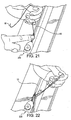
Figure 22 . Each stitch is advanced about 3 mm, back toward the first mark, and about 2/3 across the tendon. The interlocking "baseball" configuration is evident and sutures cover 360 degrees of the tendon. By covering about 2/3 of the tendon from both directions, the needles do not pass through the same point down the midline of the tendon. By passing beyond each other, a single bundle of tendon wrapped with "threads" 155 (Figure 25 ) results. Thethreads 155 may be formed of FiberWire, for example. - Upon reaching the first mark (
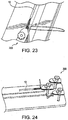
Figures 23-25 ), the very last stitch should pass slightly beyond the starting point of the very first. The two sutures are tied together with one half hitch, wrapped around the opposite side of the graft at the mark, and three additional half hitches are placed as a tight collar. In a similar manner to the stay suture technique, the needle is then passed through the center of the tendon behind the "collar." These tails will become useful as a second "stay" suture construct if one already exists at the end of the free tendon. -
Figures 26-40 illustrate a method of forming graft construct 100 ofFigures 1-3 by employing the baseball stitch technique described above with reference to a single graft strand, or a combination of the baseball stitch technique and additional stitch techniques. As noted above, exemplary graft construct 100 of the present invention comprises first region 50 (withregions single tendon strands segments single tendon strands Figure 1 ). The outside (tibialis) segment consists of two segments referred to as segment C (spans from the peg to component C) and segment D (spans from peg to component D). The outside (tibialis) segment corresponds to strand 10 ofFigure 1 that is wrapped around the inside (semitendinosus or Semi T)segment 20 of thegraft construct 100. - Placing "baseball" stitches on a composite graft to form the
construct 100 of the present invention may be conducted by the baseball stitching technique described above with reference to a single segment of graft material, with the difference that every stitch must pass through all three graft segments A, C, D. - The final graft construct 100 consists of a whip stitch begun on the peg end of segment C, each stitch passing through C, then A, then D, and advancing toward the second set of marks. The transition will occur at the second set of marks, the graft board rotated 180 degrees, and the stitches advanced through segment D, segment A and segment C, until the first set of marks is once again reached. All three segments are thus locked into one solid unit between the first and second set of marks. Simple baseball stitches are then placed on all three segments independently between the third and fourth marks. Additional details for the formation of graft construct 100 are provided below, with reference to
Figures 26-40 . - Reference is now made to
Figure 26 . A single tendon is selected for the (tibialis) outside construct. The double over diameter may be about 6.5 mm to about 8.5 mm, and the length of about 220 mm to about 230 mm. A single tendon for the (Semi T) inside construct is also selected. The double over diameter of the (Semi T) inside construct may be about 4.5 mm to about 6.0 mm, and the length of about 110 mm. Astay suture 98 is placed about 1 cm from the distal (non-fan) end of the Semi T tendon. Alternatively, it may be simpler to tie across optional component E, then transfer to component A assembly. Pass one suture tail on either side of the peg of component A, then tie three alternating half hitches (stable square knot) around peg to maintain position. The tied stay suture tails over the peg on component A of the graft preparation station should bring the distal end of the tendon into close approximation with the peg (flush to about 1 mm, but not tight enough to bend of the construct). These tails become the first pair of "pull" sutures 99. The sutures are placed one above and one below the loop of the outside construct, and they may be secured with a hemostat, for example. - Referring to
Figure 27 , component B is locked into thegraft station 200 so that the trailing edge of the clamp mechanism rests on about 0 mm (at the track limit). About 5 mm of the fan end of the Semi T tendon is clamped into component B of thegraft work station 200 and component A is locked into a position creating slight tension throughout the length of the graft. The central graft strand must be solidly fixed into the station. A stay suture is placed about 1 cm from each end of the tibialis tendon (outside construct). - The outer construct is wrapped around the peg on component A, and each
stay suture 98 is clamped firmly into components C and D (Figures 28 and 29 ). Moderate tension is placed on the tendon. -
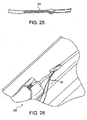
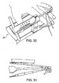
Figure 30 illustrates the entire construct placed under about 10lbs of tension. Using a ruler, for example, measurements are made on the outside strands at about 5mm from the leading edge of the peg (corresponding to the 0 point on the inside construct), about 35 mm (about 30 mm point on the inside construct), about 65 mm (about 60 mm point on the inside construct), and about 100 mm (95 mm point on the inside construct) (Figure 31 ). Based on the setup configuration, the segment marks should line up with each other. -
Figure 32 illustrates the beginning of the baseball stitch of composite three bundle portion of the graft. The stitch is made by starting nearest component A, entering the center construct at about 2 mm from tip, and exiting D strand outside the construct about 1/3 deep at the first mark, and leaving a tail which is about half of the length of the needle, as shown inFigure 32 . The tail is clamped off with a hemostat, if necessary. - Reference is now made to
Figure 33 .Needle 97 is swung beneath triple bundle, entering the C construct about one third deep at the first mark. The needle is passed through the tip of center construct, exiting D construct about 2mm from first pass, at about one third deep. InFigure 34 , the needle is swung beneath the triple bundle, the first suture pass is tightened, and the needle is passed through C strand about 3mm forward from first pass, one third deep. Passing through the center strand at one third deep, the needle is passed through the D strand at about one third deep, exiting the D strand about 3 mm from second pass. The baseball stitch is continued, incorporating all three strands in every stitch, tightening after each, passing through the tendons at about one third deep, wrapping beneath the construct, and advancing about 3 mm per stitch until reaching the second set of marks. Tension is preferably maintained on both the suture tail and the advancing suture following each stitch. When the end of the suture line is reached, preparations must be made to turn the corner. The transition stitch serves to lock the tension present at the end of the first pass, as well as set up the first stitch of the second pass. The board is then rotated 180 degrees. - Reference is now made to
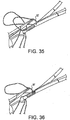
Figures 35 and 36 . For the transition stitch, the D segment is entered about 1 mm forward from the exit point of the last pass, about two thirds deep, passing through segment A at about two thirds deep, passing through segment C at about two thirds deep, and exiting about 1 mm forward from previous stitch entry point. The stitching continues, advancing back toward component A with a baseball stitch at about two thirds deep, advancing about 3 mm each stitch, and bringing each suture over the top. Care must be taken to accurately place both the entry and exit point of each advancing stitch to create uniform interlocking suture lines. Tension is preferably maintained on the advancing suture throughout the process. - Upon reaching the first mark (
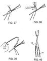
Figure 37 ), the final stitch is accomplished as follows: sweeping over the top, strand C is entered at or about 1 mm beyond the first mark, about two thirds deep, and segment A is entered at about two thirds deep, exiting the top of segment A about 1mm from the first mark; the final suture is tightened and all slack is removed from the original tail so that compression is seen at the location of the first mark, near the trailing edge of the peg; four sequential half hitches are tied at the end of the central strand, between strand C and D, maintaining tension. - As shown in
Figure 39 , with theneedle 97, one suture is passed below the looped graft, and is kept one above. The second pair of "pull"sutures 99 is created. Utilizing the described baseball stitch technique, baseball stitches 55 are placed on each tendon segment between the third and fourth marks. This may be conducted prior to performing the three bundle component if desired. - All needles are removed and pull
sutures 99 are created on each of the three free tendon segments. Two pull sutures will result at the proximal triple bundle end of the exemplary threebundle construct 100. The original stay sutures 98 may be left on the three free tendon ends, leaving double pull sutures at every position if desired (Figure 40 ). - Although the present invention has been described above with reference to the formation of graft construct 100 having stitched regions formed by a particular baseball stitching technique, the invention is not limited to this exemplary embodiment, and encompasses the formation of a graft construct having stitched regions formed by any stitching technique, or a combination of different stitching techniques, as long as the graft construct comprises single tendon strands tied or bound together, at least one of such tendon strands being adjacent (for example, wrapped around) another of the tendon strands and as shown, for example, in
Figure 1 and with reference toexemplary graft construct 100. - Although the present invention has been described above with reference to the formation of graft construct 100 having stitched regions formed by employing suture strands, the invention is not limited to sutures and contemplates embodiments wherein the stitched regions are formed with any flexible or non-flexible material or strand that can be passed through a tendon strand to facilitate stitching. According to exemplary embodiments only, the strand may be a high-strength suture such as the high strength suture sold by Arthrex, Inc. of Naples, Florida under the tradename FiberWire, which is described in
U.S. Patent 6,716,234 . FiberWire suture is formed of an advanced, high-strength fiber material, namely ultrahigh molecular weight polyethylene (UHMWPE), sold under the tradenames Spectra (Honeywell) and Dyneema (DSM), braided with at least one other fiber, natural or synthetic, to form lengths of suture material. The preferred FiberWire suture includes a core within a hollow braided construct, the core being a twisted yarn of UHMWPE. The suture may optionally include filaments of various colors. - The above description and drawings illustrate preferred embodiments which achieve the objects, features and advantages of the present invention. Although the present invention has been described in relation to particular embodiments thereof, many other variations and modifications and other uses will become apparent to those skilled in the art. Accordingly, it is not intended that the present invention be limited to the illustrated embodiments, but only by the appended claims.
Claims (16)
- A method of forming a triple bundle anterior cruciate ligament graft (100), comprising:providing a first tendon strand (20) having a first length;providing a second tendon strand (10) having a second length which is about twice the first length of the first tendon strand (20); andsecuring about one third of the second tendon strand (10) around about one third of the first tendon strand (20) by employing a suture (55), to form a triple bundle anterior cruciate ligament graft (100) having a stitched region (50) and a non-stitched region (60) comprising loose segments (12, 13, 22, 23) of said tendon strands (10, 20).
- The method of claim 1, wherein the first tendon strand (20) is a semitendonosus or a tibialis.
- The method of claim 1, wherein the second tendon strand (10) is a semitendonosus or a tibialis.
- The method of claim 1, wherein the step of securing about one third of the second tendon strand around about one third of the first tendon strand is conducted by wrapping the second tendon strand (10) around the first tendon strand (20) prior to the step of employing suture.
- A graft construct (100) for anterior cruciate ligament reconstruction, formed using the method of claim 1, comprising:a first region (50) comprising the tendon strands (10, 20) bound together by the suture (55), so that the second tendon strand (10) wraps around the first tendon strand (20); anda second region (60) comprising loose segments (12, 13, 22, 23) of said tendon strands (10, 20);wherein the length of the second tendon strand (10) is about twice the length of the first tendon strand (20), and a first strand region (21) of the first tendon strand (20) is secured to a second strand region (11) of the second tendon strand (10) by the suture (55).
- The graft construct (100) of claim 5, wherein the tendon strands of the first region (50) are bound together by the suture (55) forming a multiple pass structure on the first region.
- The graft construct (100) of claim 5, wherein the suture (55) comprises ultrahigh molecular weight polyethylene.
- The graft construct (100) of claim 5, wherein at least one of the tendon strands (10, 20) is a tibialis or a semitendonosus.
- The graft construct (100) of claim 5, wherein the first strand region (21) of the first tendon strand (20) is about one third the length of the first tissue graft.
- The graft construct (100) of claim 5, wherein the second strand region (11) of the second tendon strand (10) is about one third the length of the second tissue graft.
- The graft construct (100) of claim 5, wherein at least one of the first tissue strand (20) and the second tissue strand (10) comprises soft tissue.
- The graft construct (100) of claim 5, wherein at least one of the first tendon strand (20) and the second tendon strand (10) is a tendon.
- A graft construct (100) of claim 5, for ligament reconstruction,
wherein the second tendon strand (20) is provided adjacent the first tendon strand (10), so that the first tendon strand (10) is about perpendicular to at least a portion of the second tendon strand (20). - The graft construct (100) of claim 13, wherein a region (11) of the first tendon strand (10) is stitched to a region (21) of the second tendon strand (20) by the suture (55).
- The graft construct (100) of claim 13, wherein the first tendon strand (10) comprises at least one non-stitched region (12).
- The graft construct (100) of claim 13, wherein the second tendon strand (20) comprises at least one non-stitched region (22).
Applications Claiming Priority (1)
| Application Number | Priority Date | Filing Date | Title |
|---|---|---|---|
| US78005206P | 2006-03-08 | 2006-03-08 |
Publications (2)
| Publication Number | Publication Date |
|---|---|
| EP1832246A1 EP1832246A1 (en) | 2007-09-12 |
| EP1832246B1 true EP1832246B1 (en) | 2019-06-12 |
Family
ID=38134882
Family Applications (1)
| Application Number | Title | Priority Date | Filing Date |
|---|---|---|---|
| EP07250927.6A Active EP1832246B1 (en) | 2006-03-08 | 2007-03-06 | Bundle graft and method of making same |
Country Status (2)
| Country | Link |
|---|---|
| US (1) | US8202318B2 (en) |
| EP (1) | EP1832246B1 (en) |
Families Citing this family (127)
| Publication number | Priority date | Publication date | Assignee | Title |
|---|---|---|---|---|
| US6893462B2 (en) * | 2000-01-11 | 2005-05-17 | Regeneration Technologies, Inc. | Soft and calcified tissue implants |
| US7163541B2 (en) * | 2002-12-03 | 2007-01-16 | Arthrosurface Incorporated | Tibial resurfacing system |
| US6610067B2 (en) | 2000-05-01 | 2003-08-26 | Arthrosurface, Incorporated | System and method for joint resurface repair |
| US7896885B2 (en) | 2002-12-03 | 2011-03-01 | Arthrosurface Inc. | Retrograde delivery of resurfacing devices |
| US7678151B2 (en) * | 2000-05-01 | 2010-03-16 | Ek Steven W | System and method for joint resurface repair |
| EP2314257B9 (en) | 2000-05-01 | 2013-02-27 | ArthroSurface, Inc. | System for joint resurface repair |
| US8177841B2 (en) | 2000-05-01 | 2012-05-15 | Arthrosurface Inc. | System and method for joint resurface repair |
| US8512376B2 (en) | 2002-08-30 | 2013-08-20 | Arthrex, Inc. | Method and apparatus for internal fixation of an acromioclavicular joint dislocation of the shoulder |
| US7901408B2 (en) | 2002-12-03 | 2011-03-08 | Arthrosurface, Inc. | System and method for retrograde procedure |
| US7914545B2 (en) * | 2002-12-03 | 2011-03-29 | Arthrosurface, Inc | System and method for retrograde procedure |
| US8388624B2 (en) | 2003-02-24 | 2013-03-05 | Arthrosurface Incorporated | Trochlear resurfacing system and method |
| US7608092B1 (en) | 2004-02-20 | 2009-10-27 | Biomet Sports Medicince, LLC | Method and apparatus for performing meniscus repair |
| WO2006004885A2 (en) | 2004-06-28 | 2006-01-12 | Arthrosurface, Inc. | System for articular surface replacement |
| US8128658B2 (en) | 2004-11-05 | 2012-03-06 | Biomet Sports Medicine, Llc | Method and apparatus for coupling soft tissue to bone |
| US7749250B2 (en) | 2006-02-03 | 2010-07-06 | Biomet Sports Medicine, Llc | Soft tissue repair assembly and associated method |
| US8088130B2 (en) | 2006-02-03 | 2012-01-03 | Biomet Sports Medicine, Llc | Method and apparatus for coupling soft tissue to a bone |
| US7857830B2 (en) | 2006-02-03 | 2010-12-28 | Biomet Sports Medicine, Llc | Soft tissue repair and conduit device |
| US7909851B2 (en) | 2006-02-03 | 2011-03-22 | Biomet Sports Medicine, Llc | Soft tissue repair device and associated methods |
| US7658751B2 (en) | 2006-09-29 | 2010-02-09 | Biomet Sports Medicine, Llc | Method for implanting soft tissue |
| US7905904B2 (en) | 2006-02-03 | 2011-03-15 | Biomet Sports Medicine, Llc | Soft tissue repair device and associated methods |
| US9017381B2 (en) | 2007-04-10 | 2015-04-28 | Biomet Sports Medicine, Llc | Adjustable knotless loops |
| US8118836B2 (en) | 2004-11-05 | 2012-02-21 | Biomet Sports Medicine, Llc | Method and apparatus for coupling soft tissue to a bone |
| US8840645B2 (en) | 2004-11-05 | 2014-09-23 | Biomet Sports Medicine, Llc | Method and apparatus for coupling soft tissue to a bone |
| US8361113B2 (en) | 2006-02-03 | 2013-01-29 | Biomet Sports Medicine, Llc | Method and apparatus for coupling soft tissue to a bone |
| US20060189993A1 (en) | 2004-11-09 | 2006-08-24 | Arthrotek, Inc. | Soft tissue conduit device |
| US8303604B2 (en) | 2004-11-05 | 2012-11-06 | Biomet Sports Medicine, Llc | Soft tissue repair device and method |
| US8137382B2 (en) | 2004-11-05 | 2012-03-20 | Biomet Sports Medicine, Llc | Method and apparatus for coupling anatomical features |
| US8298262B2 (en) | 2006-02-03 | 2012-10-30 | Biomet Sports Medicine, Llc | Method for tissue fixation |
| US9801708B2 (en) | 2004-11-05 | 2017-10-31 | Biomet Sports Medicine, Llc | Method and apparatus for coupling soft tissue to a bone |
| US8998949B2 (en) | 2004-11-09 | 2015-04-07 | Biomet Sports Medicine, Llc | Soft tissue conduit device |
| US7828853B2 (en) | 2004-11-22 | 2010-11-09 | Arthrosurface, Inc. | Articular surface implant and delivery system |
| US9078644B2 (en) | 2006-09-29 | 2015-07-14 | Biomet Sports Medicine, Llc | Fracture fixation device |
| US8562645B2 (en) | 2006-09-29 | 2013-10-22 | Biomet Sports Medicine, Llc | Method and apparatus for forming a self-locking adjustable loop |
| US8652172B2 (en) | 2006-02-03 | 2014-02-18 | Biomet Sports Medicine, Llc | Flexible anchors for tissue fixation |
| US11259792B2 (en) | 2006-02-03 | 2022-03-01 | Biomet Sports Medicine, Llc | Method and apparatus for coupling anatomical features |
| US8562647B2 (en) | 2006-09-29 | 2013-10-22 | Biomet Sports Medicine, Llc | Method and apparatus for securing soft tissue to bone |
| US8506597B2 (en) | 2011-10-25 | 2013-08-13 | Biomet Sports Medicine, Llc | Method and apparatus for interosseous membrane reconstruction |
| US8652171B2 (en) | 2006-02-03 | 2014-02-18 | Biomet Sports Medicine, Llc | Method and apparatus for soft tissue fixation |
| US9538998B2 (en) | 2006-02-03 | 2017-01-10 | Biomet Sports Medicine, Llc | Method and apparatus for fracture fixation |
| US11311287B2 (en) | 2006-02-03 | 2022-04-26 | Biomet Sports Medicine, Llc | Method for tissue fixation |
| US8574235B2 (en) | 2006-02-03 | 2013-11-05 | Biomet Sports Medicine, Llc | Method for trochanteric reattachment |
| US9468433B2 (en) | 2006-02-03 | 2016-10-18 | Biomet Sports Medicine, Llc | Method and apparatus for forming a self-locking adjustable loop |
| US8251998B2 (en) | 2006-08-16 | 2012-08-28 | Biomet Sports Medicine, Llc | Chondral defect repair |
| US9149267B2 (en) | 2006-02-03 | 2015-10-06 | Biomet Sports Medicine, Llc | Method and apparatus for coupling soft tissue to a bone |
| US8771352B2 (en) | 2011-05-17 | 2014-07-08 | Biomet Sports Medicine, Llc | Method and apparatus for tibial fixation of an ACL graft |
| US9271713B2 (en) | 2006-02-03 | 2016-03-01 | Biomet Sports Medicine, Llc | Method and apparatus for tensioning a suture |
| US7959650B2 (en) | 2006-09-29 | 2011-06-14 | Biomet Sports Medicine, Llc | Adjustable knotless loops |
| US10517587B2 (en) | 2006-02-03 | 2019-12-31 | Biomet Sports Medicine, Llc | Method and apparatus for forming a self-locking adjustable loop |
| US8801783B2 (en) | 2006-09-29 | 2014-08-12 | Biomet Sports Medicine, Llc | Prosthetic ligament system for knee joint |
| US8597327B2 (en) | 2006-02-03 | 2013-12-03 | Biomet Manufacturing, Llc | Method and apparatus for sternal closure |
| US8968364B2 (en) | 2006-02-03 | 2015-03-03 | Biomet Sports Medicine, Llc | Method and apparatus for fixation of an ACL graft |
| US9918826B2 (en) | 2006-09-29 | 2018-03-20 | Biomet Sports Medicine, Llc | Scaffold for spring ligament repair |
| US8672969B2 (en) | 2006-09-29 | 2014-03-18 | Biomet Sports Medicine, Llc | Fracture fixation device |
| US11259794B2 (en) | 2006-09-29 | 2022-03-01 | Biomet Sports Medicine, Llc | Method for implanting soft tissue |
| US8500818B2 (en) | 2006-09-29 | 2013-08-06 | Biomet Manufacturing, Llc | Knee prosthesis assembly with ligament link |
| WO2008073404A2 (en) | 2006-12-11 | 2008-06-19 | Arthrosurface Incorporated | Retrograde resection apparatus and method |
| US9492270B2 (en) * | 2007-09-12 | 2016-11-15 | Alan Joel Melvin | Medical device and tension member for use in a subject |
| WO2009111481A1 (en) | 2008-03-03 | 2009-09-11 | Arthrosurface Incorporated | Bone resurfacing system and method |
| US20100049258A1 (en) * | 2008-08-19 | 2010-02-25 | Dougherty Christopher P | Single tunnel double bundle posterior cruciate ligament reconstruction |
| US9011533B2 (en) * | 2008-10-13 | 2015-04-21 | The General Hospital Corporation | Single tunnel, double bundle anterior cruciate ligament reconstruction using bone-patellar tendon-bone grafts |
| DE112010000680T5 (en) * | 2009-02-23 | 2012-12-13 | Arthrosurface, Inc. | Nanoroutly alloy substrate |
| US8439976B2 (en) * | 2009-03-31 | 2013-05-14 | Arthrex, Inc. | Integrated adjustable button-suture-graft construct with two fixation devices |
| EP2238944B1 (en) | 2009-03-31 | 2015-10-21 | Arthrex Inc | Adjustable suture button construct for tissue reconstruction |
| JP5457544B2 (en) | 2009-03-31 | 2014-04-02 | アイエムディーエス コーポレイション | Double bundle ACL repair |
| US9283076B2 (en) | 2009-04-17 | 2016-03-15 | Arthrosurface Incorporated | Glenoid resurfacing system and method |
| WO2016154393A1 (en) | 2009-04-17 | 2016-09-29 | Arthrosurface Incorporated | Glenoid repair system and methods of use thereof |
| WO2010121250A1 (en) | 2009-04-17 | 2010-10-21 | Arthrosurface Incorporated | Glenoid resurfacing system and method |
| US20100305710A1 (en) | 2009-05-28 | 2010-12-02 | Biomet Manufacturing Corp. | Knee Prosthesis |
| WO2011109836A1 (en) | 2010-03-05 | 2011-09-09 | Arthrosurface Incorporated | Tibial resurfacing system and method |
| CA2793839C (en) * | 2010-03-23 | 2018-05-22 | Boston Scientific Scimed, Inc. | Annuloplasty device |
| US9649189B2 (en) * | 2010-08-23 | 2017-05-16 | Arthrex, Inc. | Reinforced biological construct and method of reinforcing biological construct |
| US9724188B2 (en) | 2010-10-27 | 2017-08-08 | The General Hospital Corporation | System and method for ligament reconstruction |
| US9307978B2 (en) | 2010-11-04 | 2016-04-12 | Linvatec Corporation | Method and apparatus for securing an object to bone, including the provision and use of a novel suture assembly for securing an object to bone |
| US9307977B2 (en) | 2010-11-04 | 2016-04-12 | Conmed Corporation | Method and apparatus for securing an object to bone, including the provision and use of a novel suture assembly for securing suture to bone |
| EP2455040B1 (en) | 2010-11-17 | 2015-03-04 | Arthrex, Inc. | Adjustable suture-button construct for knotless stabilization of cranial cruciate deficient ligament stifle |
| EP2455001B1 (en) | 2010-11-17 | 2020-07-22 | Arthrex, Inc. | Adjustable suture-button constructs for ligament reconstruction |
| EP2455002B1 (en) | 2010-11-17 | 2019-04-03 | Arthrex, Inc. | Adjustable suture-button construct for ankle syndesmosis repair |
| WO2012107464A1 (en) * | 2011-02-08 | 2012-08-16 | Odyssea Pharma S.A. | Apparatus for knotting drawstrings of medical devices or medical devices containing drugs |
| KR102126423B1 (en) * | 2011-02-16 | 2020-06-24 | 린바텍 코포레이션 | Method and apparatus for securing an object to bone |
| US9066716B2 (en) | 2011-03-30 | 2015-06-30 | Arthrosurface Incorporated | Suture coil and suture sheath for tissue repair |
| US8574296B2 (en) | 2011-03-31 | 2013-11-05 | Biomet Manufacturing Corporation | Dual tendon bundle |
| US9301745B2 (en) | 2011-07-21 | 2016-04-05 | Arthrex, Inc. | Knotless suture constructs |
| US9332979B2 (en) | 2011-07-22 | 2016-05-10 | Arthrex, Inc. | Tensionable knotless acromioclavicular repairs and constructs |
| US9107653B2 (en) | 2011-09-22 | 2015-08-18 | Arthrex, Inc. | Tensionable knotless anchors with splice and methods of tissue repair |
| US10245016B2 (en) | 2011-10-12 | 2019-04-02 | Arthrex, Inc. | Adjustable self-locking loop constructs for tissue repairs and reconstructions |
| US8968402B2 (en) | 2011-10-18 | 2015-03-03 | Arthrocare Corporation | ACL implants, instruments, and methods |
| US9357991B2 (en) | 2011-11-03 | 2016-06-07 | Biomet Sports Medicine, Llc | Method and apparatus for stitching tendons |
| US9381013B2 (en) | 2011-11-10 | 2016-07-05 | Biomet Sports Medicine, Llc | Method for coupling soft tissue to a bone |
| US9370350B2 (en) | 2011-11-10 | 2016-06-21 | Biomet Sports Medicine, Llc | Apparatus for coupling soft tissue to a bone |
| US9314241B2 (en) | 2011-11-10 | 2016-04-19 | Biomet Sports Medicine, Llc | Apparatus for coupling soft tissue to a bone |
| EP2601894B1 (en) | 2011-12-09 | 2018-08-29 | Arthrex, Inc. | Tensionable knotless anchor systems |
| WO2013096746A1 (en) | 2011-12-22 | 2013-06-27 | Arthrosurface Incorporated | System and method for bone fixation |
| US9259217B2 (en) | 2012-01-03 | 2016-02-16 | Biomet Manufacturing, Llc | Suture Button |
| US9737292B2 (en) | 2012-06-22 | 2017-08-22 | Arthrex, Inc. | Knotless suture anchors and methods of tissue repair |
| DE112013003358T5 (en) | 2012-07-03 | 2015-03-19 | Arthrosurface, Inc. | System and procedure for joint surface replacement and repair |
| WO2014028725A1 (en) | 2012-08-17 | 2014-02-20 | On-X Life Technologies, Inc. | Biological chord repair system and methods |
| US9757119B2 (en) | 2013-03-08 | 2017-09-12 | Biomet Sports Medicine, Llc | Visual aid for identifying suture limbs arthroscopically |
| US9918827B2 (en) | 2013-03-14 | 2018-03-20 | Biomet Sports Medicine, Llc | Scaffold for spring ligament repair |
| US9492200B2 (en) | 2013-04-16 | 2016-11-15 | Arthrosurface Incorporated | Suture system and method |
| US10136886B2 (en) | 2013-12-20 | 2018-11-27 | Biomet Sports Medicine, Llc | Knotless soft tissue devices and techniques |
| US10624748B2 (en) | 2014-03-07 | 2020-04-21 | Arthrosurface Incorporated | System and method for repairing articular surfaces |
| US11607319B2 (en) | 2014-03-07 | 2023-03-21 | Arthrosurface Incorporated | System and method for repairing articular surfaces |
| US9931219B2 (en) | 2014-03-07 | 2018-04-03 | Arthrosurface Incorporated | Implant and anchor assembly |
| US9615822B2 (en) | 2014-05-30 | 2017-04-11 | Biomet Sports Medicine, Llc | Insertion tools and method for soft anchor |
| US9700291B2 (en) | 2014-06-03 | 2017-07-11 | Biomet Sports Medicine, Llc | Capsule retractor |
| US9993332B2 (en) | 2014-07-09 | 2018-06-12 | Medos International Sarl | Systems and methods for ligament graft preparation |
| US10039543B2 (en) | 2014-08-22 | 2018-08-07 | Biomet Sports Medicine, Llc | Non-sliding soft anchor |
| US10080583B2 (en) | 2014-12-12 | 2018-09-25 | Depuy Mitel, Llc | Dilator for accessing a joint space |
| US10182903B2 (en) | 2014-12-22 | 2019-01-22 | Depuy Mitek, Llc | Whip-stitching with reinforcement material |
| US9622742B2 (en) | 2014-12-29 | 2017-04-18 | Depuy Mitek, Llc | Systems and methods for preparing reinforced graft constructs |
| US9955980B2 (en) | 2015-02-24 | 2018-05-01 | Biomet Sports Medicine, Llc | Anatomic soft tissue repair |
| US9974534B2 (en) | 2015-03-31 | 2018-05-22 | Biomet Sports Medicine, Llc | Suture anchor with soft anchor of electrospun fibers |
| US10182808B2 (en) | 2015-04-23 | 2019-01-22 | DePuy Synthes Products, Inc. | Knotless suture anchor guide |
| US11331191B2 (en) | 2015-08-12 | 2022-05-17 | Howmedica Osteonics Corp. | Bioactive soft tissue implant and methods of manufacture and use thereof |
| CA2938576A1 (en) | 2015-08-12 | 2017-02-12 | Howmedica Osteonics Corp. | Methods for forming scaffolds |
| US10335136B2 (en) | 2015-08-20 | 2019-07-02 | Arthrex, Inc. | Tensionable constructs with multi-limb locking mechanism through single splice and methods of tissue repair |
| US10265060B2 (en) | 2015-08-20 | 2019-04-23 | Arthrex, Inc. | Tensionable constructs with multi-limb locking mechanism through single splice and methods of tissue repair |
| US10383720B2 (en) | 2015-12-22 | 2019-08-20 | DePuy Synthes Products, Inc. | Graft preparation system |
| US10383616B2 (en) | 2016-01-25 | 2019-08-20 | Medos International Sarl | Methods for attaching soft tissue to bone |
| CA3016171C (en) * | 2016-03-02 | 2024-02-20 | The Regents Of The University Of Michigan | Engineered tendon graft for rotator cuff repair |
| US9504557B1 (en) | 2016-03-17 | 2016-11-29 | Allosource | High-strength allograft tendon construct |
| EP3361989B1 (en) * | 2016-03-17 | 2020-08-12 | AlloSource | High-strength allograft tendon construct |
| CN111163705B (en) | 2017-07-24 | 2023-07-14 | 康曼德公司 | Self-drilling full suture anchor inserter |
| CA3108761A1 (en) | 2017-08-04 | 2019-02-07 | Arthrosurface Incorporated | Multicomponent articular surface implant |
| US11627955B2 (en) * | 2017-12-13 | 2023-04-18 | Conmed Corporation | Multi-density all suture anchor |
| US10271964B1 (en) | 2018-01-26 | 2019-04-30 | Allosource | System and methods of use for preparing and testing pre-sutured tendon constructs |
| GB2596006B (en) | 2019-03-12 | 2022-11-30 | Arthrosurface Inc | Humeral and glenoid articular surface implant systems and methods |
Family Cites Families (10)
| Publication number | Priority date | Publication date | Assignee | Title |
|---|---|---|---|---|
| GB8820766D0 (en) * | 1988-09-02 | 1988-10-05 | Beacon J P | Prosthesis |
| GB9306737D0 (en) * | 1993-03-31 | 1993-05-26 | Surgicarft Ltd | Ligament augmentation device |
| US5674224A (en) * | 1994-11-18 | 1997-10-07 | Howell; Stephen M. | Bone mulch screw assembly for endosteal fixation of soft tissue grafts and method for using same |
| FR2755846B1 (en) * | 1996-11-20 | 1998-12-31 | Jacques Philippe Laboureau | PRE-ORIENT PROSTHETIC LIGAMENT AND METHOD OF MAKING |
| GB0024903D0 (en) * | 2000-10-11 | 2000-11-22 | Ellis Dev Ltd | A textile prothesis |
| US6716234B2 (en) * | 2001-09-13 | 2004-04-06 | Arthrex, Inc. | High strength suture material |
| US20030130735A1 (en) * | 2002-01-09 | 2003-07-10 | Roger Rogalski | Graft device and methods of use |
| US6730124B2 (en) * | 2002-03-08 | 2004-05-04 | Musculoskeletal Transplant Foundation | Bone-tendon-bone assembly with cancellous allograft bone block |
| US7238189B2 (en) * | 2003-03-18 | 2007-07-03 | Arthrex, Inc. | ACL reconstruction technique using retrodrill |
| US7032599B2 (en) * | 2003-05-15 | 2006-04-25 | Mitek Surgical Products Div. Of Ethicon, Inc. | Method of replacing an anterior cruciate ligament in the knee |
-
2007
- 2007-03-06 EP EP07250927.6A patent/EP1832246B1/en active Active
- 2007-03-08 US US11/683,870 patent/US8202318B2/en active Active
Non-Patent Citations (1)
| Title |
|---|
| None * |
Also Published As
| Publication number | Publication date |
|---|---|
| EP1832246A1 (en) | 2007-09-12 |
| US8202318B2 (en) | 2012-06-19 |
| US20070239275A1 (en) | 2007-10-11 |
Similar Documents
| Publication | Publication Date | Title |
|---|---|---|
| EP1832246B1 (en) | Bundle graft and method of making same | |
| US11058531B2 (en) | Whipstitched graft construct and method of making the same | |
| USRE47811E1 (en) | Knotless suture anchors and methods of tissue repair | |
| US20230363753A1 (en) | Soft anchors with soft eyelets | |
| US9642610B2 (en) | Adjustable suture-button constructs for ligament reconstruction | |
| US8591544B2 (en) | Suture loop construct with free floating needle and method of surgery | |
| US11497484B2 (en) | Knotless self-locking anchor constructs and methods of tissue fixation | |
| US20150297211A1 (en) | Method for knotless tensionable rotator cuff repair | |
| US20130023928A1 (en) | Knotless suture constructs | |
| US20190269397A1 (en) | Surgical constructs and methods of tissue repair | |
| US11564675B2 (en) | Knotless instability suture anchor construct and system | |
| US20190282283A1 (en) | Method and system for providing a suture wrap cerclage | |
| US10143506B2 (en) | Method and system for providing a suture wrap cerclage | |
| US20220378486A1 (en) | Surgical system and method including cerclage with loop | |
| KR20180126014A (en) | High-strength allograft tendon structure | |
| US20210401567A1 (en) | Surgical fixation systems and associated methods for performing tissue repairs | |
| US20230309984A1 (en) | Tensionable Knotless Anchors and Methods of Tissue Repair | |
| JP2023551986A (en) | Tensionable, knotless anchors and methods of tissue repair |
Legal Events
| Date | Code | Title | Description |
|---|---|---|---|
| PUAI | Public reference made under article 153(3) epc to a published international application that has entered the european phase |
Free format text: ORIGINAL CODE: 0009012 |
|
| AK | Designated contracting states |
Kind code of ref document: A1 Designated state(s): AT BE BG CH CY CZ DE DK EE ES FI FR GB GR HU IE IS IT LI LT LU LV MC MT NL PL PT RO SE SI SK TR |
|
| AX | Request for extension of the european patent |
Extension state: AL BA HR MK YU |
|
| 17P | Request for examination filed |
Effective date: 20080312 |
|
| 17Q | First examination report despatched |
Effective date: 20080414 |
|
| AKX | Designation fees paid |
Designated state(s): AT BE BG CH CY CZ DE DK EE ES FI FR GB GR HU IE IS IT LI LT LU LV MC MT NL PL PT RO SE SI SK TR |
|
| GRAP | Despatch of communication of intention to grant a patent |
Free format text: ORIGINAL CODE: EPIDOSNIGR1 |
|
| STAA | Information on the status of an ep patent application or granted ep patent |
Free format text: STATUS: GRANT OF PATENT IS INTENDED |
|
| INTG | Intention to grant announced |
Effective date: 20181221 |
|
| GRAS | Grant fee paid |
Free format text: ORIGINAL CODE: EPIDOSNIGR3 |
|
| GRAA | (expected) grant |
Free format text: ORIGINAL CODE: 0009210 |
|
| STAA | Information on the status of an ep patent application or granted ep patent |
Free format text: STATUS: THE PATENT HAS BEEN GRANTED |
|
| AK | Designated contracting states |
Kind code of ref document: B1 Designated state(s): AT BE BG CH CY CZ DE DK EE ES FI FR GB GR HU IE IS IT LI LT LU LV MC MT NL PL PT RO SE SI SK TR |
|
| REG | Reference to a national code |
Ref country code: GB Ref legal event code: FG4D |
|
| REG | Reference to a national code |
Ref country code: CH Ref legal event code: EP |
|
| REG | Reference to a national code |
Ref country code: AT Ref legal event code: REF Ref document number: 1141600 Country of ref document: AT Kind code of ref document: T Effective date: 20190615 |
|
| REG | Reference to a national code |
Ref country code: DE Ref legal event code: R096 Ref document number: 602007058559 Country of ref document: DE |
|
| REG | Reference to a national code |
Ref country code: IE Ref legal event code: FG4D |
|
| REG | Reference to a national code |
Ref country code: NL Ref legal event code: MP Effective date: 20190612 |
|
| REG | Reference to a national code |
Ref country code: LT Ref legal event code: MG4D |
|
| PG25 | Lapsed in a contracting state [announced via postgrant information from national office to epo] |
Ref country code: FI Free format text: LAPSE BECAUSE OF FAILURE TO SUBMIT A TRANSLATION OF THE DESCRIPTION OR TO PAY THE FEE WITHIN THE PRESCRIBED TIME-LIMIT Effective date: 20190612 Ref country code: LT Free format text: LAPSE BECAUSE OF FAILURE TO SUBMIT A TRANSLATION OF THE DESCRIPTION OR TO PAY THE FEE WITHIN THE PRESCRIBED TIME-LIMIT Effective date: 20190612 Ref country code: ES Free format text: LAPSE BECAUSE OF FAILURE TO SUBMIT A TRANSLATION OF THE DESCRIPTION OR TO PAY THE FEE WITHIN THE PRESCRIBED TIME-LIMIT Effective date: 20190612 Ref country code: SE Free format text: LAPSE BECAUSE OF FAILURE TO SUBMIT A TRANSLATION OF THE DESCRIPTION OR TO PAY THE FEE WITHIN THE PRESCRIBED TIME-LIMIT Effective date: 20190612 |
|
| PG25 | Lapsed in a contracting state [announced via postgrant information from national office to epo] |
Ref country code: GR Free format text: LAPSE BECAUSE OF FAILURE TO SUBMIT A TRANSLATION OF THE DESCRIPTION OR TO PAY THE FEE WITHIN THE PRESCRIBED TIME-LIMIT Effective date: 20190913 Ref country code: LV Free format text: LAPSE BECAUSE OF FAILURE TO SUBMIT A TRANSLATION OF THE DESCRIPTION OR TO PAY THE FEE WITHIN THE PRESCRIBED TIME-LIMIT Effective date: 20190612 Ref country code: BG Free format text: LAPSE BECAUSE OF FAILURE TO SUBMIT A TRANSLATION OF THE DESCRIPTION OR TO PAY THE FEE WITHIN THE PRESCRIBED TIME-LIMIT Effective date: 20190912 |
|
| REG | Reference to a national code |
Ref country code: AT Ref legal event code: MK05 Ref document number: 1141600 Country of ref document: AT Kind code of ref document: T Effective date: 20190612 |
|
| PG25 | Lapsed in a contracting state [announced via postgrant information from national office to epo] |
Ref country code: EE Free format text: LAPSE BECAUSE OF FAILURE TO SUBMIT A TRANSLATION OF THE DESCRIPTION OR TO PAY THE FEE WITHIN THE PRESCRIBED TIME-LIMIT Effective date: 20190612 Ref country code: NL Free format text: LAPSE BECAUSE OF FAILURE TO SUBMIT A TRANSLATION OF THE DESCRIPTION OR TO PAY THE FEE WITHIN THE PRESCRIBED TIME-LIMIT Effective date: 20190612 Ref country code: RO Free format text: LAPSE BECAUSE OF FAILURE TO SUBMIT A TRANSLATION OF THE DESCRIPTION OR TO PAY THE FEE WITHIN THE PRESCRIBED TIME-LIMIT Effective date: 20190612 Ref country code: CZ Free format text: LAPSE BECAUSE OF FAILURE TO SUBMIT A TRANSLATION OF THE DESCRIPTION OR TO PAY THE FEE WITHIN THE PRESCRIBED TIME-LIMIT Effective date: 20190612 Ref country code: PT Free format text: LAPSE BECAUSE OF FAILURE TO SUBMIT A TRANSLATION OF THE DESCRIPTION OR TO PAY THE FEE WITHIN THE PRESCRIBED TIME-LIMIT Effective date: 20191014 Ref country code: AT Free format text: LAPSE BECAUSE OF FAILURE TO SUBMIT A TRANSLATION OF THE DESCRIPTION OR TO PAY THE FEE WITHIN THE PRESCRIBED TIME-LIMIT Effective date: 20190612 Ref country code: SK Free format text: LAPSE BECAUSE OF FAILURE TO SUBMIT A TRANSLATION OF THE DESCRIPTION OR TO PAY THE FEE WITHIN THE PRESCRIBED TIME-LIMIT Effective date: 20190612 |
|
| PG25 | Lapsed in a contracting state [announced via postgrant information from national office to epo] |
Ref country code: IS Free format text: LAPSE BECAUSE OF FAILURE TO SUBMIT A TRANSLATION OF THE DESCRIPTION OR TO PAY THE FEE WITHIN THE PRESCRIBED TIME-LIMIT Effective date: 20191012 Ref country code: IT Free format text: LAPSE BECAUSE OF FAILURE TO SUBMIT A TRANSLATION OF THE DESCRIPTION OR TO PAY THE FEE WITHIN THE PRESCRIBED TIME-LIMIT Effective date: 20190612 |
|
| REG | Reference to a national code |
Ref country code: DE Ref legal event code: R097 Ref document number: 602007058559 Country of ref document: DE |
|
| PG25 | Lapsed in a contracting state [announced via postgrant information from national office to epo] |
Ref country code: TR Free format text: LAPSE BECAUSE OF FAILURE TO SUBMIT A TRANSLATION OF THE DESCRIPTION OR TO PAY THE FEE WITHIN THE PRESCRIBED TIME-LIMIT Effective date: 20190612 |
|
| PLBE | No opposition filed within time limit |
Free format text: ORIGINAL CODE: 0009261 |
|
| STAA | Information on the status of an ep patent application or granted ep patent |
Free format text: STATUS: NO OPPOSITION FILED WITHIN TIME LIMIT |
|
| PG25 | Lapsed in a contracting state [announced via postgrant information from national office to epo] |
Ref country code: DK Free format text: LAPSE BECAUSE OF FAILURE TO SUBMIT A TRANSLATION OF THE DESCRIPTION OR TO PAY THE FEE WITHIN THE PRESCRIBED TIME-LIMIT Effective date: 20190612 Ref country code: PL Free format text: LAPSE BECAUSE OF FAILURE TO SUBMIT A TRANSLATION OF THE DESCRIPTION OR TO PAY THE FEE WITHIN THE PRESCRIBED TIME-LIMIT Effective date: 20190612 |
|
| 26N | No opposition filed |
Effective date: 20200313 |
|
| PG25 | Lapsed in a contracting state [announced via postgrant information from national office to epo] |
Ref country code: IS Free format text: LAPSE BECAUSE OF FAILURE TO SUBMIT A TRANSLATION OF THE DESCRIPTION OR TO PAY THE FEE WITHIN THE PRESCRIBED TIME-LIMIT Effective date: 20200224 Ref country code: SI Free format text: LAPSE BECAUSE OF FAILURE TO SUBMIT A TRANSLATION OF THE DESCRIPTION OR TO PAY THE FEE WITHIN THE PRESCRIBED TIME-LIMIT Effective date: 20190612 |
|
| PG2D | Information on lapse in contracting state deleted |
Ref country code: IS |
|
| PG25 | Lapsed in a contracting state [announced via postgrant information from national office to epo] |
Ref country code: IS Free format text: LAPSE BECAUSE OF FAILURE TO SUBMIT A TRANSLATION OF THE DESCRIPTION OR TO PAY THE FEE WITHIN THE PRESCRIBED TIME-LIMIT Effective date: 20191112 |
|
| PG25 | Lapsed in a contracting state [announced via postgrant information from national office to epo] |
Ref country code: MC Free format text: LAPSE BECAUSE OF FAILURE TO SUBMIT A TRANSLATION OF THE DESCRIPTION OR TO PAY THE FEE WITHIN THE PRESCRIBED TIME-LIMIT Effective date: 20190612 |
|
| REG | Reference to a national code |
Ref country code: CH Ref legal event code: PL |
|
| REG | Reference to a national code |
Ref country code: BE Ref legal event code: MM Effective date: 20200331 |
|
| PG25 | Lapsed in a contracting state [announced via postgrant information from national office to epo] |
Ref country code: LU Free format text: LAPSE BECAUSE OF NON-PAYMENT OF DUE FEES Effective date: 20200306 |
|
| PG25 | Lapsed in a contracting state [announced via postgrant information from national office to epo] |
Ref country code: LI Free format text: LAPSE BECAUSE OF NON-PAYMENT OF DUE FEES Effective date: 20200331 Ref country code: IE Free format text: LAPSE BECAUSE OF NON-PAYMENT OF DUE FEES Effective date: 20200306 Ref country code: CH Free format text: LAPSE BECAUSE OF NON-PAYMENT OF DUE FEES Effective date: 20200331 |
|
| PG25 | Lapsed in a contracting state [announced via postgrant information from national office to epo] |
Ref country code: BE Free format text: LAPSE BECAUSE OF NON-PAYMENT OF DUE FEES Effective date: 20200331 |
|
| PG25 | Lapsed in a contracting state [announced via postgrant information from national office to epo] |
Ref country code: MT Free format text: LAPSE BECAUSE OF FAILURE TO SUBMIT A TRANSLATION OF THE DESCRIPTION OR TO PAY THE FEE WITHIN THE PRESCRIBED TIME-LIMIT Effective date: 20190612 Ref country code: CY Free format text: LAPSE BECAUSE OF FAILURE TO SUBMIT A TRANSLATION OF THE DESCRIPTION OR TO PAY THE FEE WITHIN THE PRESCRIBED TIME-LIMIT Effective date: 20190612 |
|
| PGFP | Annual fee paid to national office [announced via postgrant information from national office to epo] |
Ref country code: FR Payment date: 20230110 Year of fee payment: 17 |
|
| PGFP | Annual fee paid to national office [announced via postgrant information from national office to epo] |
Ref country code: GB Payment date: 20230112 Year of fee payment: 17 Ref country code: DE Payment date: 20230110 Year of fee payment: 17 |