EP1832107B1 - A portable electronic device for capturing images - Google Patents
A portable electronic device for capturing images Download PDFInfo
- Publication number
- EP1832107B1 EP1832107B1 EP05702529A EP05702529A EP1832107B1 EP 1832107 B1 EP1832107 B1 EP 1832107B1 EP 05702529 A EP05702529 A EP 05702529A EP 05702529 A EP05702529 A EP 05702529A EP 1832107 B1 EP1832107 B1 EP 1832107B1
- Authority
- EP
- European Patent Office
- Prior art keywords
- reflector
- electronic device
- lighting element
- camera
- movable
- Prior art date
- Legal status (The legal status is an assumption and is not a legal conclusion. Google has not performed a legal analysis and makes no representation as to the accuracy of the status listed.)
- Expired - Lifetime
Links
- 230000008859 change Effects 0.000 claims abstract description 13
- 229910052724 xenon Inorganic materials 0.000 claims description 29
- FHNFHKCVQCLJFQ-UHFFFAOYSA-N xenon atom Chemical compound [Xe] FHNFHKCVQCLJFQ-UHFFFAOYSA-N 0.000 claims description 29
- 238000000034 method Methods 0.000 claims description 8
- 230000008878 coupling Effects 0.000 claims description 6
- 238000010168 coupling process Methods 0.000 claims description 6
- 238000005859 coupling reaction Methods 0.000 claims description 6
- 230000001419 dependent effect Effects 0.000 claims 2
- 230000003287 optical effect Effects 0.000 description 6
- 230000001413 cellular effect Effects 0.000 description 3
- 238000003384 imaging method Methods 0.000 description 2
- 230000007246 mechanism Effects 0.000 description 2
- 230000000717 retained effect Effects 0.000 description 2
- 230000001960 triggered effect Effects 0.000 description 2
- 230000008901 benefit Effects 0.000 description 1
- 239000003990 capacitor Substances 0.000 description 1
- 230000003247 decreasing effect Effects 0.000 description 1
- 230000001678 irradiating effect Effects 0.000 description 1
- 238000005360 mashing Methods 0.000 description 1
- 239000000203 mixture Substances 0.000 description 1
- 238000012986 modification Methods 0.000 description 1
- 230000004048 modification Effects 0.000 description 1
Images



Classifications
-
- H—ELECTRICITY
- H04—ELECTRIC COMMUNICATION TECHNIQUE
- H04M—TELEPHONIC COMMUNICATION
- H04M1/00—Substation equipment, e.g. for use by subscribers
- H04M1/02—Constructional features of telephone sets
- H04M1/0202—Portable telephone sets, e.g. cordless phones, mobile phones or bar type handsets
- H04M1/0206—Portable telephones comprising a plurality of mechanically joined movable body parts, e.g. hinged housings
- H04M1/0208—Portable telephones comprising a plurality of mechanically joined movable body parts, e.g. hinged housings characterized by the relative motions of the body parts
- H04M1/0214—Foldable telephones, i.e. with body parts pivoting to an open position around an axis parallel to the plane they define in closed position
- H04M1/0216—Foldable in one direction, i.e. using a one degree of freedom hinge
- H04M1/0218—The hinge comprising input and/or output user interface means
-
- H—ELECTRICITY
- H04—ELECTRIC COMMUNICATION TECHNIQUE
- H04M—TELEPHONIC COMMUNICATION
- H04M1/00—Substation equipment, e.g. for use by subscribers
- H04M1/02—Constructional features of telephone sets
- H04M1/0202—Portable telephone sets, e.g. cordless phones, mobile phones or bar type handsets
- H04M1/026—Details of the structure or mounting of specific components
- H04M1/0264—Details of the structure or mounting of specific components for a camera module assembly
-
- H—ELECTRICITY
- H04—ELECTRIC COMMUNICATION TECHNIQUE
- H04N—PICTORIAL COMMUNICATION, e.g. TELEVISION
- H04N23/00—Cameras or camera modules comprising electronic image sensors; Control thereof
- H04N23/56—Cameras or camera modules comprising electronic image sensors; Control thereof provided with illuminating means
-
- H—ELECTRICITY
- H04—ELECTRIC COMMUNICATION TECHNIQUE
- H04N—PICTORIAL COMMUNICATION, e.g. TELEVISION
- H04N23/00—Cameras or camera modules comprising electronic image sensors; Control thereof
- H04N23/58—Means for changing the camera field of view without moving the camera body, e.g. nutating or panning of optics or image sensors
-
- H—ELECTRICITY
- H04—ELECTRIC COMMUNICATION TECHNIQUE
- H04M—TELEPHONIC COMMUNICATION
- H04M2250/00—Details of telephonic subscriber devices
- H04M2250/20—Details of telephonic subscriber devices including a rotatable camera
Definitions
- Embodiments of the present invention relate to a portable electronic device for capturing images.
- they relate to a portable electronic device for capturing images in a plurality of directions relative to the main body of the device.
- a camera captures an image by recording the light that enters its aperture, from a subject.
- many cameras use an electronic flash.
- An electronic flash is arranged so that at the time that the image is captured, a burst of light is emitted in the direction from which the image is captured, improving the quality of the image.
- a movable camera element is used.
- the camera element may rotate about an axis, enabling a user to capture images from a plurality of directions relative to the main body of the device.
- Rotatable cameras are particularly popular in mobile telephones, as they enable the camera to be directed towards the user of that mobile telephone during video calls and they enable the user to capture images from a direction away from him at other times.
- Portable electronic devices that incorporate such rotatable camera apertures may also incorporate a lighting element to improve the level of light entering the aperture when capturing images in low light conditions.
- the lighting element is typically a white LED, fixed at a position within the housing of the telephone. If the user rotates the camera to capture images in a different direction, the direction in which light is emitted by the lighting element may no longer correspond with the direction from which images are captured. He may therefore be unable to use the lighting element when capturing such an image.
- the user may decide to rotate the whole body of the device to capture an image from a different direction. However, the user may then not be able to see the display.
- Flash circuitry is used to drive an electronic flash.
- Previous proposals have put the whole of the flash circuitry into the movable flash element, to avoid the use of moving contacts, in view of the high current and voltages required by the flash tube.
- this results in a very large movable flash element due to the size of some of the components of the flash circuitry, such as the main capacitor.
- JP 2004-343502 discloses an imaging device comprising a reflector, a reflector driving part and a stroboscope.
- the reflector driving part turns the reflector behind the stroboscope in order to condense emitted light in accordance with a distance up to an object.
- US 6,400,905 discloses a device including a discharge tube, a prism unit, a first optical unit and a second optical unit.
- the prism unit has a receiving surface that receives light from the discharge tube and an outgoing surface that ejects light to an object to be photographed.
- the first optical unit and the second optical unit are disposed on the prism unit on the side of the object to be photographed. A relative interval between the first optical unit and the second optical unit may be changed to vary an irradiating angle of the light directed towards the object to be photographed.
- US 6,573,939 discloses a digital camera comprising an imaging unit which is rotatably connected to a camera body.
- the camera body includes a flash unit which includes a light emitting unit.
- the light emitting unit includes a xenon discharge lamp surrounded by a reflector which directs the light from the xenon discharge lamp,
- the light emitting unit may be rotatable.
- the reflector may be rotatable.
- an electronic device having a main body, the device comprising: a camera arrangement for capturing images in a plurality of directions relative to the main body of the device; a lighting element; a reflector, at least a portion of which is movable about the lighting element to change the direction of light from the lighting element; a voltage source for providing a voltage to operate the lighting element; and a wiper connector for electrically connecting the voltage source to the reflector, in order to apply a voltage to the reflector to operate the lighting element, wherein a point of connection between the wiper connector and the reflector is variable in dependence upon movement of the reflector about the lighting element.
- the camera arrangement may comprise a camera with an aperture movable relative to the main body to change the direction from which images are captured.
- the camera aperture may be movable by a user.
- the camera aperture may be movable by rotation.
- the reflector may be movable by a user.
- the reflector may be movable by rotation around the lighting element.
- the camera aperture and the reflector may be movable by rotation around substantially parallel axes.
- the camera aperture and the reflector may be movable by rotation around substantially the same axis.
- the device may further comprise coupling means acting between the reflector and the camera arrangement and so arranged that movement of the camera aperture causes movement of the reflector.
- the coupling means may be arranged to provide at least two positions for the camera aperture at which there is substantial alignment between the direction from which images are captured and the direction to which light is reflected, in use, by the reflector.
- the camera arrangement may be for capturing images in a first direction and in a second direction which is substantially opposite to the first direction.
- the reflector may have a curved surface.
- the reflector may be paraboloidal.
- the lighting element may have an elongate portion and the reflector may be movable around the elongate portion.
- the lighting element may be fixedly positioned in the main body.
- the device may further comprise drive circuitry which is fixedly positioned in the main body of the device to operate the lighting element.
- the lighting element may comprise a xenon tube.
- the xenon may be at least partially ionisable by the application of a voltage to the reflector.
- the reflector may comprise two co-operating separate reflecting parts that are arranged for relative movement.
- a first part of the reflector may be rotatable about the lighting element and a second part of the reflector may be fixed in relation to the main body of the device.
- An electrical connection between the second fixed part of the reflector and a voltage source may have a fixed connection point at the second fixed part of the reflector.
- a method comprising: moving at least a portion of a reflector to be moved about a lighting element to change the direction of light from the lighting element and to vary a point of connection between a wiper connector and the reflector, wherein the wiper connector electrically connects the reflector and a voltage source, and the voltage source is operable to apply a voltage to the reflector to operate the lighting element; and capturing an image with the camera arrangement using the directed light from the lighting element.
- the camera arrangement may be adjusted to change the direction from which images are captured, to correspond with the direction to which light is directed by the reflector.
- the figures illustrate a portable electronic device 100/200/300 having a main body 42, the device 100/200/300 comprising: a camera arrangement 32 for capturing images in a plurality of directions relative to the main body 42 of the device 100/200/300; a lighting element 14; and a reflector 12, at least a portion of which is movable about the lighting element 14 to change the direction of light reflected from the lighting element 14.
- Figs 1 and 2 illustrate a flash unit 10 for use in the device 100/200/300.
- the flash unit 10 comprises a paraboloidal reflector 12, a lighting element 14, an electrical connector 16 and electrical connectors 22.
- the lighting element 14 is typically a xenon tube.
- the xenon tube 14 is used to create a short flash of light with a high intensity while an image is being captured, to allow the user to capture a better quality image.
- a reflector 12 is used.
- the xenon gas mixture in the tube must be ionised. Ionisation is achieved by applying a trigger pulse of a very high voltage (such as a few thousand volts) but low current, close to the tube 14. When the xenon gas has been ionised, current is then able to flow through the tube 14 between the connectors 22, causing the xenon to generate light.
- the voltage that is used to ionise the xenon in the xenon tube 14 is commonly known as the "trigger voltage”.
- the trigger voltage is applied to the reflector 12, which is metallic or metalised.
- the voltage is applied using the electrical connector 16.
- the reflector 12 also acts as a "trigger plate".
- the current which flows through the xenon tube 14, between the connectors 22, is much higher than the current carried by the trigger plate.
- the lighting element 14 is an elongate, cylindrical xenon tube.
- the reflector 12 is elongate, curved and located around the tube 14, leaving a gap 44. Light leaves the tube 14 in all directions, but any light which does not pass directly through the gap 44 in the reflector 12 will be reflected towards the gap 44.
- the tube 14 and the reflector 12 are positioned in such a way that the light exits in the general direction of the large arrow 20.
- the geometry of the tube 14 and the reflector 12, such as the relative positioning of the tube 14 and the reflector 12, the curvature of the reflector 12 and the size of the gap 44, can be used to set configuration of the beam of light emitted from the gap 44. For instance, a larger gap 44 in the reflector 12 will result in a wider beam of light being emitted from the gap 44.
- the flash unit 10 may also comprise a lens 48 to direct the light after it has been emitted from the gap 44.
- the reflector 12 is rotatable about the xenon tube 14 in the direction of arrow 18, to change the direction 20, relative to the tube 14. If the flash unit comprises a lens 48, the lens 48 may also rotate with the reflector 12.
- the reflector 12 can rotate around at least 180°. By rotating the reflector 12, therefore, the user may direct the light where he chooses without having to rotate the whole of the flash unit 10.
- the position of the connector 16 remains fixed.
- the reflector 12 therefore rotates relative to the connector 16 and the point of connection 52 between the connector 16 and the reflector 12 therefore varies as the reflector 12 moves, but the ability to apply the trigger voltage to the reflector 12 is retained as the reflector moves.
- the connection between the reflector 12 and the flash circuitry 80 is required to carry a very high voltage (the trigger voltage) but very low current. As a consequence of this, a wiper connector 16 such as that illustrated in Figs 1 and 2 is adequate.
- the flash circuitry 80 is used to generate the high trigger voltage to be applied to the reflector 12, and also the current required for the connectors 22, after the flash has been triggered.
- Figure 3 illustrates a flash unit 10 which also comprises a connecting rail 24.
- the reflector 12 may rotate through 360° relative to the axis of the tube 14 while maintaining a connection with connector 16.
- the tube 14 can be triggered at any position of the reflector 12.
- the direction 20 can be changed by turning the reflector 12 relative to the tube 14, but without requiring the tube 14 to turn, and without losing the ability to apply the trigger voltage to the reflector 12.
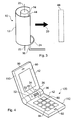
- FIG 4 shows how the flash unit 10 of Figs 1, 2 or 3 may be incorporated into the clamshell hand portable radio telephone 100.
- the radio telephone 100 comprises communications circuitry, as known in the art, allowing it to operate as a telephone in a cellular network.
- the radio telephone 100 has a first housing 110 and a second housing 112.
- the first and second housings 110 and 112 are rotatably connected by a hinge 26.
- the first housing 110 comprises a display 60 and an earpiece 90
- the second housing 112 comprises a keypad 94 and a microphone 92.
- the flash circuitry 80 is fixedly positioned in the second housing 112.
- the hinge 26 comprises a camera housing 32 with an aperture 33.
- a camera contained in the housing 32 is used to capture images through the aperture 33.
- the camera housing 32 is rotatable in the direction of the arrow 36. Accordingly, the direction in which images are captured by the camera, through the aperture 33, can be changed relative to the device 100. In a particular example, images can be captured at least in two directions which are 180° apart, toward the user and away from the user, when the user is holding the device 100 to view the display 60 and operate the keypad 94.
- the flash housing 34 contains the reflector 12.
- the flash tube 14 is mounted to the housing 112 and extends into the flash housing 34.
- the flash housing 34 is also rotatable in the direction of arrow 36, causing the reflector 12 to rotate about the tube 14, as described above.
- the flash housing 34 comprises a window 40 corresponding with the position of the gap 44. Rotation of the housing 34 therefore changes the direction 20 of the light produced.
- the flash housing 34 is preferably able to turn to direct light over the same range of directions as the camera is able to capture images, so that the subject can always be illuminated.
- the housing 34 preferably at least has two available positions, directed in a first direction towards the user as he looks at the display 60, and another directed in a second direction which is substantially opposite to the first direction, the second direction being away from the user as he looks at the display 60.
- a detent or latch arrangement may be provided to allow the flash housing 34 and camera housing 32 to be retained at these positions.
- the camera housing 32 and the flash housing 34 may therefore be directed towards the user when he wishes to take a picture of himself and away from the user when he wishes to take pictures of other things.
- the position of the device 100 can remain constant and comfortable for viewing the screen 60.
- the xenon tube 14 and the flash circuitry 80 do not move relative to the housing 112.
- no movement of the display 60 or the keypad 94 is required when the user wishes to capture images in different directions, using the camera and the flash unit 10.
- the flash housing 34 may be coupled to the camera housing 32 so that rotation of the flash housing 34 also causes the housings 32, 34, to rotate together. Similarly, rotation of the camera housing 32 by the user will also cause rotation of the flash housing 34, in this example.
- a cylindrical xenon tube 14 is fixed in position within and aligned with the rotation axis of the housing 34, which is also preferably the axis of the hinge 26.
- the flash circuitry 80 is fixedly positioned in the second housing 112 of the main body 42 of the clamshell device 100. Consequently the flash circuitry 80 and the xenon tube 14 do not move in relation to one another even when the flash housing 34 is turned.
- the connectors 22 which connect the xenon tube 14 to the flash circuitry 80 are therefore not required to accommodate movement and can readily be designed to carry the high current which flows through the connectors 22. Consequently, the problems associated with having to provide thick, moving connectors for high current are avoided.
- a rotating flash arrangement is thus provided by embodiments of the invention, while keeping the xenon tube 14 and the flash circuitry 80 fixed in position relative to one another and to the main body 42 of the device 100.
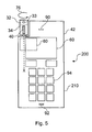
- Fig. 5 illustrates a further hand portable radio telephone 200 which comprises the flash unit 10 of Figs 1, 2 or 3 .
- the radio telephone 200 illustrated in Fig. 5 has a housing 210, which comprises a display 60, an earpiece 90, a microphone 92 and a keypad 94.
- the radio telephone 200 also comprises communications circuitry, as known in the art, enabling it to operate as a telephone in a cellular network.
- a rotatable camera housing 32 and a rotatable flash housing 34 are again provided, located in this example, at one corner of the device 200.
- the arrow 76 shows the direction of rotation of both the camera housing 32 and the flash housing 34 relative to the main body 42 of the device 200, about a common axis x.
- the xenon tube 14 is elongate and cylindrical. The xenon tube 14 is mounted within the device 200 so that it extends into the flash housing 34 and so that its elongate axis is aligned with the rotation axis x.
- the reflector 12 is mounted in the flash housing 34, around the tube 14.
- the flash housing 34 may rotate with the camera housing 32, or the camera housing 32 and the flash housing 34 may rotate separately.
- the flash housing 34 is preferably able to turn to direct light over the same range of directions as the camera is able to capture images by turning the camera housing 32.
- Fig. 6 illustrates another hand portable radiotelephone 300 which incorporates the flash unit 10 of Figs 1, 2 or 3 .
- the radio telephone 300 illustrated in Fig. 6 has a housing 310, which comprises a display 60, an earpiece 90, a microphone 92 and a keypad 94.
- the radio telephone 300 also comprises communications circuitry, as known in the art, enabling it to operate as a telephone in a cellular network.
- the flash housing 34 may be constructed in the same manner as the flash housing of fig 5 , and is arranged to be rotatable in a first sense indicated by the arrow 70.
- the camera housing 32 is generally similar to the housing 32 of fig 5 , but is arranged alongside the housing 34, so that the respective rotation axes are parallel but not coincident.
- the housing 32 rotates in the opposite sense to flash housing 34, as indicated by the arrow 72.
- the camera housing 32 and the flash housing 34 are coupled so that rotational movement of one of the camera housing 32 or the flash housing 34 causes the rotational movement of the other in the opposite direction.
- each may carry a gear ring, the gear rings mashing to create the coupling.
- friction may be used to provide the coupling.
- the camera aperture 33 and the flash housing 34 will face the same direction only when they are in one of two positions: a first position in which both the aperture 33 and the housing 34 are facing the user as he looks at the display 60, and a second, different, position in which both the aperture and the housing 34 are facing away from the user as he looks at the display 60. Accordingly, the flash direction and the image capture direction are aligned at the two most common image capture directions.
- the reflector 12 is in two parts.
- the reflector 12 has a curved movable part 12a and a curved fixed part 12b.
- the fixed part 12b of the reflector is fixed relative to the tube 14 and acts as the trigger plate.
- the fixed part 12b of the reflector is fixed relative to a housing of the device.
- the movable part 12a may be rotated in the direction 18a back to its position in Fig. 7 .
- a lens 48 may be provided at the points at which the light is emitted from the reflector arrangement 12, to direct the light.
- Fig. 7 is advantageous in that the direction in which light is emitted from the flash unit 10 may be changed by 180° through a relatively small amount of rotation of the movable part 12a (i.e. much less than the 180° change in the direction of emitted light).
- a further advantage is that as the fixed part 12b is fixed relative the main body of the device that it is incorporated in, the connector 16 need not move and the connection point between the connector 16 and the fixed part 12b need not move.
- Fig. 8 also illustrates a flash unit 10 which comprises a two part reflector 12.
- the embodiment in Fig. 8 is similar to that in Fig. 7 in that the fixed part 12b of the reflector 12 is fixed relative to the tube 14 and the movable part 12a of the reflector 12 is rotatable in directions 18a and 18b.
- the embodiment in Fig. 8 is different to that in Fig. 7 , however, in that the direction 20b in which light is emitted from the new gap after rotation of the movable part 12a in the direction 18b is not opposite to the direction 20a in which the light was initially emitted from the gap 44.
- the size and relative positioning of the movable part 12a and the fixed part 12b may be altered as required so that rotation of the movable part 12a allows light to leave the flash unit 10 in any two desired directions.
- Each of the hand portable radiotelephones 100/200/300 in Figs 4 , 5 and 6 have a flash housing 34 with a front window 40.
- the movable part 12a of the reflector 12 rotates with the flash housing 34 when it is rotated, but the fixed part 12b remains fixed.
- a second window may be incorporated in the flash housing 34 to allow the light to be emitted from the flash housing 34 when the movable part 12a has been rotated in the direction 18b.
- the second window is on the opposite side of the flash housing 34 to the first window 40.
- a gearing mechanism may be used to couple the camera housing 32 to the flash housing 34.
- the movable part 12a of the reflector 12 moves with the flash housing 34, while the fixed part 12b remains fixed relative to the main body of the device 100/200/300.
- a relatively small amount of rotation of the flash housing 34 results in a relatively large amount of rotation of the camera housing 32, ensuring that the camera aperture 33 faces in the same direction as the direction that light is emitted from the flash housing 34.
- the lighting element 14 may be a white LED rather than a xenon tube.
- the camera arrangement may comprise two separate cameras, each of which is fixed but are directed in two different directions, instead of a movable camera and housing.
- a user interface would allow the user to select which camera direction he wishes to use.
- the movable flash housing could then be positioned manually or automatically according to which camera aperture the user has chosen to use.
- the electrical connector 16 which connects to the reflector 12 to the flash circuitry 80 may have a fixed connection point in the Fig 1, 2 and 3 embodiments of the flash unit 10, the connector 16 being a flexible connector.
Landscapes
- Engineering & Computer Science (AREA)
- Signal Processing (AREA)
- Multimedia (AREA)
- Human Computer Interaction (AREA)
- Studio Devices (AREA)
- Stroboscope Apparatuses (AREA)
- Telephone Set Structure (AREA)
- Photographic Developing Apparatuses (AREA)
- Printers Or Recording Devices Using Electromagnetic And Radiation Means (AREA)
Abstract
Description
- Embodiments of the present invention relate to a portable electronic device for capturing images. In particular, they relate to a portable electronic device for capturing images in a plurality of directions relative to the main body of the device.
- A camera captures an image by recording the light that enters its aperture, from a subject. In order to improve the quality of an image in low light conditions, many cameras use an electronic flash. An electronic flash is arranged so that at the time that the image is captured, a burst of light is emitted in the direction from which the image is captured, improving the quality of the image.
- In some more recent devices, a movable camera element is used. The camera element may rotate about an axis, enabling a user to capture images from a plurality of directions relative to the main body of the device. Rotatable cameras are particularly popular in mobile telephones, as they enable the camera to be directed towards the user of that mobile telephone during video calls and they enable the user to capture images from a direction away from him at other times.
- Portable electronic devices that incorporate such rotatable camera apertures may also incorporate a lighting element to improve the level of light entering the aperture when capturing images in low light conditions. The lighting element is typically a white LED, fixed at a position within the housing of the telephone. If the user rotates the camera to capture images in a different direction, the direction in which light is emitted by the lighting element may no longer correspond with the direction from which images are captured. He may therefore be unable to use the lighting element when capturing such an image.
- Alternatively, the user may decide to rotate the whole body of the device to capture an image from a different direction. However, the user may then not be able to see the display.
- Flash circuitry is used to drive an electronic flash. Previous proposals have put the whole of the flash circuitry into the movable flash element, to avoid the use of moving contacts, in view of the high current and voltages required by the flash tube. However, this results in a very large movable flash element due to the size of some of the components of the flash circuitry, such as the main capacitor.
-
JP 2004-343502 -
US 6,400,905 discloses a device including a discharge tube, a prism unit, a first optical unit and a second optical unit. The prism unit has a receiving surface that receives light from the discharge tube and an outgoing surface that ejects light to an object to be photographed. The first optical unit and the second optical unit are disposed on the prism unit on the side of the object to be photographed. A relative interval between the first optical unit and the second optical unit may be changed to vary an irradiating angle of the light directed towards the object to be photographed. -
US 6,573,939 discloses a digital camera comprising an imaging unit which is rotatably connected to a camera body. The camera body includes a flash unit which includes a light emitting unit. The light emitting unit includes a xenon discharge lamp surrounded by a reflector which directs the light from the xenon discharge lamp, The light emitting unit may be rotatable. Alternatively, the reflector may be rotatable. - According to a first aspect of the present invention, there is provided an electronic device having a main body, the device comprising: a camera arrangement for capturing images in a plurality of directions relative to the main body of the device; a lighting element; a reflector, at least a portion of which is movable about the lighting element to change the direction of light from the lighting element; a voltage source for providing a voltage to operate the lighting element; and a wiper connector for electrically connecting the voltage source to the reflector, in order to apply a voltage to the reflector to operate the lighting element, wherein a point of connection between the wiper connector and the reflector is variable in dependence upon movement of the reflector about the lighting element.
- The camera arrangement may comprise a camera with an aperture movable relative to the main body to change the direction from which images are captured. The camera aperture may be movable by a user. The camera aperture may be movable by rotation.
- The reflector may be movable by a user. The reflector may be movable by rotation around the lighting element. The camera aperture and the reflector may be movable by rotation around substantially parallel axes. The camera aperture and the reflector may be movable by rotation around substantially the same axis.
- The device may further comprise coupling means acting between the reflector and the camera arrangement and so arranged that movement of the camera aperture causes movement of the reflector. The coupling means may be arranged to provide at least two positions for the camera aperture at which there is substantial alignment between the direction from which images are captured and the direction to which light is reflected, in use, by the reflector.
- The camera arrangement may be for capturing images in a first direction and in a second direction which is substantially opposite to the first direction. The reflector may have a curved surface. The reflector may be paraboloidal. The lighting element may have an elongate portion and the reflector may be movable around the elongate portion.
- The lighting element may be fixedly positioned in the main body. The device may further comprise drive circuitry which is fixedly positioned in the main body of the device to operate the lighting element.
- The lighting element may comprise a xenon tube. The xenon may be at least partially ionisable by the application of a voltage to the reflector.
- The reflector may comprise two co-operating separate reflecting parts that are arranged for relative movement. A first part of the reflector may be rotatable about the lighting element and a second part of the reflector may be fixed in relation to the main body of the device. An electrical connection between the second fixed part of the reflector and a voltage source may have a fixed connection point at the second fixed part of the reflector.
- According to a second aspect of the present invention, there is provided a method, comprising: moving at least a portion of a reflector to be moved about a lighting element to change the direction of light from the lighting element and to vary a point of connection between a wiper connector and the reflector, wherein the wiper connector electrically connects the reflector and a voltage source, and the voltage source is operable to apply a voltage to the reflector to operate the lighting element; and capturing an image with the camera arrangement using the directed light from the lighting element.
- The camera arrangement may be adjusted to change the direction from which images are captured, to correspond with the direction to which light is directed by the reflector.
- For a better understanding of the present invention reference will now be made by way of example only to the accompanying drawings in which:
-
Fig. 1 illustrates a side elevation of a flash unit; -
Fig. 2 illustrates a perspective view of the flash unit; -
Fig. 3 illustrates a flash unit incorporating a connecting rail; -
Fig. 4 illustrates a first portable radio telephone comprising a rotating flash unit; -
Fig. 5 illustrates a second portable radio telephone comprising a rotating flash unit; -
Fig. 6 illustrates a third portable radio telephone comprising a rotating flash unit; -
Fig. 7 illustrates a side elevation of a flash unit with a two part reflector; and -
Fig. 8 illustrates a side elevation of a further flash unit with a two part reflector. - The figures illustrate a portable
electronic device 100/200/300 having amain body 42, thedevice 100/200/300 comprising: acamera arrangement 32 for capturing images in a plurality of directions relative to themain body 42 of thedevice 100/200/300; alighting element 14; and areflector 12, at least a portion of which is movable about thelighting element 14 to change the direction of light reflected from thelighting element 14. -
Figs 1 and 2 illustrate aflash unit 10 for use in thedevice 100/200/300. Theflash unit 10 comprises aparaboloidal reflector 12, alighting element 14, anelectrical connector 16 andelectrical connectors 22. Thelighting element 14 is typically a xenon tube. Thexenon tube 14 is used to create a short flash of light with a high intensity while an image is being captured, to allow the user to capture a better quality image. In order to direct the light produced by theelement 14 towards the subject, areflector 12 is used. - In order to produce light using the
xenon tube 14, the xenon gas mixture in the tube must be ionised. Ionisation is achieved by applying a trigger pulse of a very high voltage (such as a few thousand volts) but low current, close to thetube 14. When the xenon gas has been ionised, current is then able to flow through thetube 14 between theconnectors 22, causing the xenon to generate light. The voltage that is used to ionise the xenon in thexenon tube 14 is commonly known as the "trigger voltage". - In
Figs 1 and 2 , the trigger voltage is applied to thereflector 12, which is metallic or metalised. The voltage is applied using theelectrical connector 16. In this case, therefore, thereflector 12 also acts as a "trigger plate". The current which flows through thexenon tube 14, between theconnectors 22, is much higher than the current carried by the trigger plate. - In the embodiment illustrated in
Figs 1 and 2 , thelighting element 14 is an elongate, cylindrical xenon tube. Thereflector 12 is elongate, curved and located around thetube 14, leaving agap 44. Light leaves thetube 14 in all directions, but any light which does not pass directly through thegap 44 in thereflector 12 will be reflected towards thegap 44. Thetube 14 and thereflector 12 are positioned in such a way that the light exits in the general direction of thelarge arrow 20. - The geometry of the
tube 14 and thereflector 12, such as the relative positioning of thetube 14 and thereflector 12, the curvature of thereflector 12 and the size of thegap 44, can be used to set configuration of the beam of light emitted from thegap 44. For instance, alarger gap 44 in thereflector 12 will result in a wider beam of light being emitted from thegap 44. Theflash unit 10 may also comprise alens 48 to direct the light after it has been emitted from thegap 44. - The
reflector 12 is rotatable about thexenon tube 14 in the direction ofarrow 18, to change thedirection 20, relative to thetube 14. If the flash unit comprises alens 48, thelens 48 may also rotate with thereflector 12. - In both
Figs 1 and 2 , it can be seen that thereflector 12 can rotate around at least 180°. By rotating thereflector 12, therefore, the user may direct the light where he chooses without having to rotate the whole of theflash unit 10. - As the
reflector 12 rotates, the position of theconnector 16 remains fixed. Thereflector 12 therefore rotates relative to theconnector 16 and the point ofconnection 52 between theconnector 16 and thereflector 12 therefore varies as thereflector 12 moves, but the ability to apply the trigger voltage to thereflector 12 is retained as the reflector moves. - The connection between the
reflector 12 and theflash circuitry 80 is required to carry a very high voltage (the trigger voltage) but very low current. As a consequence of this, awiper connector 16 such as that illustrated inFigs 1 and 2 is adequate. - The
electrical connector 16 which connects to thereflector 12, and theelectrodes 22 which connect to thexenon tube 14, are all connected toflash circuitry 80 within thedevice 100/200/300 (seefigs 4 to 6 ). Theflash circuitry 80 is used to generate the high trigger voltage to be applied to thereflector 12, and also the current required for theconnectors 22, after the flash has been triggered. -
Figure 3 illustrates aflash unit 10 which also comprises a connectingrail 24. By incorporating a connectingrail 24, thereflector 12 may rotate through 360° relative to the axis of thetube 14 while maintaining a connection withconnector 16. Thus, thetube 14 can be triggered at any position of thereflector 12. - In each of these examples, it can be seen that the
direction 20 can be changed by turning thereflector 12 relative to thetube 14, but without requiring thetube 14 to turn, and without losing the ability to apply the trigger voltage to thereflector 12. -
Figure 4 shows how theflash unit 10 ofFigs 1, 2 or3 may be incorporated into the clamshell handportable radio telephone 100. Theradio telephone 100 comprises communications circuitry, as known in the art, allowing it to operate as a telephone in a cellular network. Theradio telephone 100 has afirst housing 110 and asecond housing 112. The first andsecond housings hinge 26. Thefirst housing 110 comprises adisplay 60 and anearpiece 90, and thesecond housing 112 comprises akeypad 94 and amicrophone 92. Theflash circuitry 80 is fixedly positioned in thesecond housing 112. - The
hinge 26 comprises acamera housing 32 with anaperture 33. A camera contained in thehousing 32 is used to capture images through theaperture 33. Thecamera housing 32 is rotatable in the direction of thearrow 36. Accordingly, the direction in which images are captured by the camera, through theaperture 33, can be changed relative to thedevice 100. In a particular example, images can be captured at least in two directions which are 180° apart, toward the user and away from the user, when the user is holding thedevice 100 to view thedisplay 60 and operate thekeypad 94. - The
flash housing 34 contains thereflector 12. Theflash tube 14 is mounted to thehousing 112 and extends into theflash housing 34. Theflash housing 34 is also rotatable in the direction ofarrow 36, causing thereflector 12 to rotate about thetube 14, as described above. Theflash housing 34 comprises awindow 40 corresponding with the position of thegap 44. Rotation of thehousing 34 therefore changes thedirection 20 of the light produced. - The
flash housing 34 is preferably able to turn to direct light over the same range of directions as the camera is able to capture images, so that the subject can always be illuminated. In particular, thehousing 34 preferably at least has two available positions, directed in a first direction towards the user as he looks at thedisplay 60, and another directed in a second direction which is substantially opposite to the first direction, the second direction being away from the user as he looks at thedisplay 60. A detent or latch arrangement may be provided to allow theflash housing 34 andcamera housing 32 to be retained at these positions. - The
camera housing 32 and theflash housing 34 may therefore be directed towards the user when he wishes to take a picture of himself and away from the user when he wishes to take pictures of other things. The position of thedevice 100 can remain constant and comfortable for viewing thescreen 60. However, when thecamera housing 32 or theflash housing 34 are moved, thexenon tube 14 and theflash circuitry 80 do not move relative to thehousing 112. Furthermore, no movement of thedisplay 60 or thekeypad 94 is required when the user wishes to capture images in different directions, using the camera and theflash unit 10. - The
flash housing 34 may be coupled to thecamera housing 32 so that rotation of theflash housing 34 also causes thehousings camera housing 32 by the user will also cause rotation of theflash housing 34, in this example. - In the embodiment illustrated in
Fig. 4 , acylindrical xenon tube 14 is fixed in position within and aligned with the rotation axis of thehousing 34, which is also preferably the axis of thehinge 26. Theflash circuitry 80 is fixedly positioned in thesecond housing 112 of themain body 42 of theclamshell device 100. Consequently theflash circuitry 80 and thexenon tube 14 do not move in relation to one another even when theflash housing 34 is turned. Theconnectors 22 which connect thexenon tube 14 to theflash circuitry 80 are therefore not required to accommodate movement and can readily be designed to carry the high current which flows through theconnectors 22. Consequently, the problems associated with having to provide thick, moving connectors for high current are avoided. A rotating flash arrangement is thus provided by embodiments of the invention, while keeping thexenon tube 14 and theflash circuitry 80 fixed in position relative to one another and to themain body 42 of thedevice 100. -
Fig. 5 illustrates a further handportable radio telephone 200 which comprises theflash unit 10 ofFigs 1, 2 or3 . Theradio telephone 200 illustrated inFig. 5 has ahousing 210, which comprises adisplay 60, anearpiece 90, amicrophone 92 and akeypad 94. Theradio telephone 200 also comprises communications circuitry, as known in the art, enabling it to operate as a telephone in a cellular network. - A
rotatable camera housing 32 and arotatable flash housing 34 are again provided, located in this example, at one corner of thedevice 200. Thearrow 76 shows the direction of rotation of both thecamera housing 32 and theflash housing 34 relative to themain body 42 of thedevice 200, about a common axis x. In the embodiment shown inFig. 5 , thexenon tube 14 is elongate and cylindrical. Thexenon tube 14 is mounted within thedevice 200 so that it extends into theflash housing 34 and so that its elongate axis is aligned with the rotation axis x. - In a similar fashion to the
flash housing 34 described in relation toFig 4 , thereflector 12 is mounted in theflash housing 34, around thetube 14. Thus, when theflash housing 34 is rotated in the direction ofarrow 36, thereflector 12 therefore also rotates, around thetube 14, thereby redirecting the light output relative to thedevice 200. Furthermore, theflash housing 34 may rotate with thecamera housing 32, or thecamera housing 32 and theflash housing 34 may rotate separately. Again, theflash housing 34 is preferably able to turn to direct light over the same range of directions as the camera is able to capture images by turning thecamera housing 32. -
Fig. 6 illustrates another handportable radiotelephone 300 which incorporates theflash unit 10 ofFigs 1, 2 or3 . Theradio telephone 300 illustrated inFig. 6 has ahousing 310, which comprises adisplay 60, anearpiece 90, amicrophone 92 and akeypad 94. Theradio telephone 300 also comprises communications circuitry, as known in the art, enabling it to operate as a telephone in a cellular network. - In this embodiment, the
flash housing 34 may be constructed in the same manner as the flash housing offig 5 , and is arranged to be rotatable in a first sense indicated by thearrow 70. Thecamera housing 32 is generally similar to thehousing 32 offig 5 , but is arranged alongside thehousing 34, so that the respective rotation axes are parallel but not coincident. Moreover, thehousing 32 rotates in the opposite sense to flashhousing 34, as indicated by thearrow 72. Thecamera housing 32 and theflash housing 34 are coupled so that rotational movement of one of thecamera housing 32 or theflash housing 34 causes the rotational movement of the other in the opposite direction. For example, each may carry a gear ring, the gear rings mashing to create the coupling. Alternatively, friction may be used to provide the coupling. Thecamera aperture 33 and theflash housing 34 will face the same direction only when they are in one of two positions: a first position in which both theaperture 33 and thehousing 34 are facing the user as he looks at thedisplay 60, and a second, different, position in which both the aperture and thehousing 34 are facing away from the user as he looks at thedisplay 60. Accordingly, the flash direction and the image capture direction are aligned at the two most common image capture directions. - Two further embodiments of the
flash unit 10 are illustrated inFigs 7 and 8 . In both of the embodiments, thereflector 12 is in two parts. Thereflector 12 has a curvedmovable part 12a and a curvedfixed part 12b. In these embodiments, thefixed part 12b of the reflector is fixed relative to thetube 14 and acts as the trigger plate. When incorporated into a portable device, thefixed part 12b of the reflector is fixed relative to a housing of the device. - In the configuration shown in
Fig. 7 , when light is emitted from thetube 14, it either passes directly through thegap 44 or it is reflected by theparts reflector 12 towards thegap 44. Light is therefore emitted through thegap 44 in the general direction oflarge arrow 20a. Themovable part 12a is rotatable in thedirection 18b. When themovable part 12a is rotated in thedirection 18b, it may be positioned such that it obscures thegap 44. In this instance, a new gap is created at the opposite side offlash unit 10, between themovable part 12a and thefixed part 12b. Light from thetube 14 will then exit thereflector arrangement 12 in the direction oflarge arrow 20b, which is substantially opposite todirection 20a. - In order to close the gap that has been formed by the rotation of the
movable part 12a in thedirection 18b and to restore thegap 44 between themovable part 12a and thefixed part 12b, themovable part 12a may be rotated in thedirection 18a back to its position inFig. 7 . - A
lens 48 may be provided at the points at which the light is emitted from thereflector arrangement 12, to direct the light. - The configuration of
Fig. 7 is advantageous in that the direction in which light is emitted from theflash unit 10 may be changed by 180° through a relatively small amount of rotation of themovable part 12a (i.e. much less than the 180° change in the direction of emitted light). A further advantage is that as thefixed part 12b is fixed relative the main body of the device that it is incorporated in, theconnector 16 need not move and the connection point between theconnector 16 and thefixed part 12b need not move. -
Fig. 8 also illustrates aflash unit 10 which comprises a twopart reflector 12. The embodiment inFig. 8 is similar to that inFig. 7 in that thefixed part 12b of thereflector 12 is fixed relative to thetube 14 and themovable part 12a of thereflector 12 is rotatable indirections Fig. 8 is different to that inFig. 7 , however, in that thedirection 20b in which light is emitted from the new gap after rotation of themovable part 12a in thedirection 18b is not opposite to thedirection 20a in which the light was initially emitted from thegap 44. This can be achieved by increasing the size of thefixed part 12b, decreasing the size of themovable part 12a and changing the relative positioning of the twoparts movable part 12a and thefixed part 12b may be altered as required so that rotation of themovable part 12a allows light to leave theflash unit 10 in any two desired directions. - Each of the hand
portable radiotelephones 100/200/300 inFigs 4 ,5 and6 have aflash housing 34 with afront window 40. However, when the embodiments ofFig. 7 and Fig. 8 are incorporated into atelephone 100/200/300, themovable part 12a of thereflector 12 rotates with theflash housing 34 when it is rotated, but thefixed part 12b remains fixed. A second window may be incorporated in theflash housing 34 to allow the light to be emitted from theflash housing 34 when themovable part 12a has been rotated in thedirection 18b. In the case of theFig. 7 embodiment, the second window is on the opposite side of theflash housing 34 to thefirst window 40. - When the
Fig. 7 and Fig. 8 embodiments are incorporated into theradio telephones 100/200/300 inFigs 4 ,5 and6 , a gearing mechanism may be used to couple thecamera housing 32 to theflash housing 34. Themovable part 12a of thereflector 12 moves with theflash housing 34, while thefixed part 12b remains fixed relative to the main body of thedevice 100/200/300. Using the gearing mechanism, a relatively small amount of rotation of theflash housing 34 results in a relatively large amount of rotation of thecamera housing 32, ensuring that thecamera aperture 33 faces in the same direction as the direction that light is emitted from theflash housing 34. - Although embodiments of the invention have been described in the preceding paragraphs with reference to various examples, it should be appreciated that modifications to the examples given can be made without departing from the scope of the invention as claimed. For example, the
lighting element 14 may be a white LED rather than a xenon tube. - The camera arrangement may comprise two separate cameras, each of which is fixed but are directed in two different directions, instead of a movable camera and housing. A user interface would allow the user to select which camera direction he wishes to use. The movable flash housing could then be positioned manually or automatically according to which camera aperture the user has chosen to use.
- The
electrical connector 16 which connects to thereflector 12 to theflash circuitry 80 may have a fixed connection point in theFig 1, 2 and3 embodiments of theflash unit 10, theconnector 16 being a flexible connector.
Claims (26)
- An electronic device (100, 200, 300) having a main body (42), the device comprising:a camera arrangement (32) for capturing images in a plurality of directions relative to the main body of the device;a lighting element (14);a reflector (12), at least a portion of which is movable about the lighting element to change the direction of light from the lighting element;a voltage source (80) for providing a voltage to operate the lighting element; anda wiper connector (16) for electrically connecting the voltage source to the reflector, in order to apply a voltage to the reflector to operate the lighting element, whereina point of connection between the wiper connector and the reflector is variable in dependence upon movement of the reflector about the lighting element.
- An electronic device as claimed in claim 1, wherein the camera arrangement comprises a camera with an aperture (33) movable relative to the main body to change the direction from which images are captured.
- An electronic device as claimed in claim 2, wherein the camera aperture is movable by a user.
- An electronic device as claimed in claim 2 or 3, wherein the camera aperture is movable by rotation.
- An electronic device as claimed in any of the preceding claims, wherein the reflector is movable by a user.
- An electronic device as claimed in any of the preceding claims, wherein the reflector is movable by rotation around the lighting element.
- An electronic device as claimed in claim 6, when dependent on claim 4, wherein the camera aperture and the reflector are movable by rotation around substantially parallel axes.
- An electronic device as claimed in claim 6, when dependent on claim 4, wherein the camera aperture and the reflector are movable by rotation around substantially the same axis.
- An electronic device as claimed in any of claims 2 to 8, wherein the device further comprises coupling means acting between the reflector and the camera arrangement and so arranged that movement of the camera aperture causes movement of the reflector.
- An electronic device as claimed in claim 9, wherein the coupling means is arranged to provide at least two positions for the camera aperture at which there is substantial alignment between the direction from which images are captured and the direction to which light is reflected, in use, by the reflector.
- An electronic device as claimed in any of the preceding claims, wherein the camera arrangement is for capturing images in a first direction and in a second direction which is substantially opposite to the first direction.
- An electronic device as claimed in any of the preceding claims, wherein the reflector has a curved surface.
- An electronic device as claimed in claim 12, wherein the reflector is paraboloidal.
- An electronic device as claimed in any of the preceding claims, wherein the lighting element has an elongate portion and the reflector is movable around the elongate portion.
- An electronic device as claimed in any of the preceding claims, wherein the lighting element is fixedly positioned in the main body.
- An electronic device as claimed in any of the preceding claims, wherein the voltage source is fixedly positioned in the main body of the device.
- An electronic device as claimed in any of the preceding claims, wherein the connector that connects the lighting element and the voltage source is fixedly positioned in the main body.
- An electronic device as claimed in any of the preceding claims, wherein the lighting element comprises a xenon tube.
- An electronic device as claimed in claim 18, wherein the xenon is at least partially ionisable by the application of a voltage to the reflector.
- A method, comprising:moving at least a portion of a reflector (12) about a lighting element (14) to change the direction of light from the lighting element and to vary a point of connection between a wiper connector (16) and the reflector, wherein the connector electrically connects the reflector and voltage source (80), and the voltage source is operable to apply a voltage to the reflector to operate the lighting element; andcapturing an image with a camera arrangement (32) using the directed light from the lighting element.
- A method as claimed in claim 20, further comprising adjusting the camera arrangement to change the direction from which images are captured, to correspond with the direction to which light is directed by the reflector.
- A method as claimed in claim 20 or 21, wherein the voltage source and the lighting element are fixedly positioned in a body of an electronic device.
- A method as claimed in claim 20, 21 or 22, wherein the reflector rotates about the lighting element to change the direction of light from the lighting element.
- A method as claimed in any of claims 20 to 23, wherein the reflector has a curved surface.
- A method as claimed in any of claims 20 to 24, wherein the reflector is moved by a user.
- A method as claimed in any of claims 20 to 25, wherein the lighting element comprises a xenon tube, and xenon in the xenon tube is ionised by the application of a voltage to the reflector.
Applications Claiming Priority (1)
| Application Number | Priority Date | Filing Date | Title |
|---|---|---|---|
| PCT/IB2005/000437 WO2006087599A1 (en) | 2005-02-18 | 2005-02-18 | A portable electronic device for capturing images |
Publications (2)
| Publication Number | Publication Date |
|---|---|
| EP1832107A1 EP1832107A1 (en) | 2007-09-12 |
| EP1832107B1 true EP1832107B1 (en) | 2010-08-11 |
Family
ID=36916170
Family Applications (1)
| Application Number | Title | Priority Date | Filing Date |
|---|---|---|---|
| EP05702529A Expired - Lifetime EP1832107B1 (en) | 2005-02-18 | 2005-02-18 | A portable electronic device for capturing images |
Country Status (7)
| Country | Link |
|---|---|
| US (1) | US7969503B2 (en) |
| EP (1) | EP1832107B1 (en) |
| JP (1) | JP4468995B2 (en) |
| CN (1) | CN101124814B (en) |
| AT (1) | ATE477672T1 (en) |
| DE (1) | DE602005022932D1 (en) |
| WO (1) | WO2006087599A1 (en) |
Families Citing this family (18)
| Publication number | Priority date | Publication date | Assignee | Title |
|---|---|---|---|---|
| CN2706974Y (en) * | 2004-06-18 | 2005-06-29 | 鸿富锦精密工业(深圳)有限公司 | Cellphone with night visual function |
| WO2007054332A1 (en) * | 2005-11-10 | 2007-05-18 | OBE OHNMACHT & BAUMGäRTNER GMBH & CO. KG | Camera chip, camera and method for image recording |
| US7634191B2 (en) * | 2006-06-21 | 2009-12-15 | Sony Ericsson Mobile Communications Ab | Portable communication device equipped with an electronic flash having a LED ignition device |
| US7567287B2 (en) * | 2006-09-20 | 2009-07-28 | Sony Ericsson Mobile Communications Ab | Rotating prism for a digital camera in a portable mobile communication device |
| JP2010078770A (en) * | 2008-09-25 | 2010-04-08 | Casio Computer Co Ltd | Imaging apparatus |
| US8184158B2 (en) * | 2009-10-28 | 2012-05-22 | Chen Kun-Sen | Curved mirror camera |
| JP5486275B2 (en) * | 2009-11-25 | 2014-05-07 | パナソニック液晶ディスプレイ株式会社 | Liquid crystal display |
| KR101627192B1 (en) * | 2009-12-02 | 2016-06-07 | 삼성전자주식회사 | Image pickup apparatus, Flash apparatus usable with image pickup apparatus, and Control method for Image pickup apparatus |
| EP2552100A1 (en) * | 2011-07-26 | 2013-01-30 | Research in Motion Corporation | Stereoscopic image capturing system |
| US20130027521A1 (en) * | 2011-07-26 | 2013-01-31 | Research In Motion Corporation | Stereoscopic image capturing system |
| US10457441B2 (en) | 2012-01-05 | 2019-10-29 | Portero Holdings, Llc | Case for a communication device |
| GB2506398B (en) * | 2012-09-28 | 2016-09-14 | Frameblast Ltd | Camera apparatus |
| US9423671B2 (en) | 2013-02-14 | 2016-08-23 | Olloclip, Llc | Accessories for communication devices |
| US9571151B2 (en) | 2014-02-06 | 2017-02-14 | Olloclip, Llc | Cases for mobile electronic devices configured to receive auxiliary optical devices |
| EP3227816A4 (en) * | 2014-12-03 | 2018-07-04 | Princeton Identity, Inc. | System and method for mobile device biometric add-on |
| CN104965567B (en) * | 2015-06-19 | 2019-04-26 | 联想(北京)有限公司 | Electronic equipment |
| KR102401285B1 (en) * | 2016-04-01 | 2022-05-24 | 삼성전자주식회사 | Electronic device comprising display |
| US20190260863A1 (en) * | 2016-08-30 | 2019-08-22 | Xleap, Inc. | Information processing terminal |
Citations (3)
| Publication number | Priority date | Publication date | Assignee | Title |
|---|---|---|---|---|
| US5408389A (en) * | 1993-09-07 | 1995-04-18 | Burlingame; Glen E. | Interrupted light source |
| US6400905B1 (en) * | 1999-08-26 | 2002-06-04 | Canon Kabushiki Kaisha | Lighting angle variable lighting device |
| JP2004343502A (en) * | 2003-05-16 | 2004-12-02 | Fuji Photo Film Co Ltd | Imaging device |
Family Cites Families (32)
| Publication number | Priority date | Publication date | Assignee | Title |
|---|---|---|---|---|
| NL7014266A (en) * | 1970-09-29 | 1972-04-04 | ||
| DE2446411A1 (en) | 1974-09-28 | 1976-04-08 | Rollei Werke Franke Heidecke | FLASH UNIT WITH CABLE COMPARTMENT |
| DE7815176U1 (en) * | 1978-05-19 | 1979-02-08 | Patent-Treuhand-Gesellschaft Fuer Elektrische Gluehlampen Mbh, 8000 Muenchen | LIGHTING DEVICE |
| US5126778A (en) * | 1991-07-16 | 1992-06-30 | Eastman Kodak Company | Dedicated photographic flash system for varying flash spread based upon camera-to-subject distance |
| US5539622A (en) * | 1992-03-12 | 1996-07-23 | Asahi Kogaku Kogyo Kabushiki Kaisha | Strobe device |
| US5347339A (en) * | 1992-04-17 | 1994-09-13 | Olympus Optical Co., Ltd. | Strobe apparatus |
| US5406343A (en) * | 1994-01-13 | 1995-04-11 | Eastman Kodak Company | Alternative direct and combined direct-indirect light reflecting device |
| JP3132991B2 (en) * | 1995-09-18 | 2001-02-05 | ウエスト電気株式会社 | Variable illumination angle flash device |
| JPH09113969A (en) * | 1995-10-20 | 1997-05-02 | Ricoh Co Ltd | Variable strobe light strobe device |
| JP4001958B2 (en) * | 1996-08-19 | 2007-10-31 | ソニー株式会社 | Imaging device |
| US5717964A (en) * | 1997-02-18 | 1998-02-10 | Eastman Kodak Company | Camera exposure apparatus having flash tubes for correcting for overexposure |
| DE862079T1 (en) * | 1997-02-28 | 1999-03-04 | Ricoh Co., Ltd., Tokio/Tokyo | Digital camera with synchronized lens and flash movements |
| US6750916B1 (en) * | 1997-05-30 | 2004-06-15 | Olympus Corporation | Protective lid having a flash unit incorporated therein for a digital camera |
| GB2321955B (en) * | 1997-06-03 | 2002-06-19 | Leslie Adrian Alfred Woolard | An illumination method and device |
| US5999751A (en) * | 1997-12-03 | 1999-12-07 | Fuji Photo Film Co., Ltd. | Flash device and reflector for flash discharge tube |
| US6337953B1 (en) * | 1998-11-16 | 2002-01-08 | Konica Corporation | Strobe device of lens-fitted film unit and production method of the strobe device |
| JP2001320622A (en) * | 2000-05-11 | 2001-11-16 | Fuji Photo Film Co Ltd | Mobile phone with camera |
| EP1276308A3 (en) * | 2001-07-12 | 2005-05-04 | Kabushiki Kaisha Toshiba | Mobile communication terminal comprising camera |
| TWI225743B (en) * | 2002-03-19 | 2004-12-21 | Mitsubishi Electric Corp | Mobile telephone device having camera and illumination device for camera |
| JP4395859B2 (en) * | 2003-01-07 | 2010-01-13 | 三星電機株式会社 | Camera module for portable terminals |
| KR100524747B1 (en) * | 2003-04-16 | 2005-11-01 | 엘지전자 주식회사 | Driver device of camera assembly for mobile image phone and control method thereof |
| JP4171339B2 (en) | 2003-04-17 | 2008-10-22 | オリンパス株式会社 | Light reflector and flash light emitting device using the same |
| KR20040100746A (en) * | 2003-05-24 | 2004-12-02 | 삼성전자주식회사 | Device and method for compensating photographing of back light in mobile telephone with camera |
| ATE422782T1 (en) * | 2003-07-04 | 2009-02-15 | Lg Electronics Inc | ROTATABLE CAMERA FOR A MOBILE COMMUNICATIONS DEVICE |
| KR100703495B1 (en) * | 2003-07-16 | 2007-04-03 | 삼성전자주식회사 | Two-way sliding type portable terminal |
| JP4526790B2 (en) * | 2003-07-24 | 2010-08-18 | ソニー株式会社 | Manufacturing method of flash unit |
| US7092626B2 (en) * | 2003-07-28 | 2006-08-15 | Canon Kabushiki Kaisha | Placement of light-emitting section in image sensing apparatus |
| JP4260568B2 (en) * | 2003-07-31 | 2009-04-30 | 京セラ株式会社 | Camera apparatus and image processing control method |
| JP4111886B2 (en) * | 2003-08-12 | 2008-07-02 | 三洋電機株式会社 | Member for insulation and holding of terminal part |
| TWM241908U (en) * | 2003-09-09 | 2004-08-21 | High Tech Comp Corp | Rotatable image catching device |
| TWI260905B (en) * | 2005-05-17 | 2006-08-21 | Jin-Chiuan Huang | Lens turning device for mobile phone with camera function |
| KR100677475B1 (en) * | 2005-07-14 | 2007-02-02 | 엘지전자 주식회사 | Camera FPC Installation Structure and Installation Method of Portable Terminal |
-
2005
- 2005-02-18 EP EP05702529A patent/EP1832107B1/en not_active Expired - Lifetime
- 2005-02-18 JP JP2007555716A patent/JP4468995B2/en not_active Expired - Fee Related
- 2005-02-18 WO PCT/IB2005/000437 patent/WO2006087599A1/en not_active Ceased
- 2005-02-18 US US11/884,625 patent/US7969503B2/en not_active Expired - Fee Related
- 2005-02-18 DE DE602005022932T patent/DE602005022932D1/en not_active Expired - Lifetime
- 2005-02-18 AT AT05702529T patent/ATE477672T1/en not_active IP Right Cessation
- 2005-02-18 CN CN2005800484935A patent/CN101124814B/en not_active Expired - Fee Related
Patent Citations (3)
| Publication number | Priority date | Publication date | Assignee | Title |
|---|---|---|---|---|
| US5408389A (en) * | 1993-09-07 | 1995-04-18 | Burlingame; Glen E. | Interrupted light source |
| US6400905B1 (en) * | 1999-08-26 | 2002-06-04 | Canon Kabushiki Kaisha | Lighting angle variable lighting device |
| JP2004343502A (en) * | 2003-05-16 | 2004-12-02 | Fuji Photo Film Co Ltd | Imaging device |
Also Published As
| Publication number | Publication date |
|---|---|
| JP2008530934A (en) | 2008-08-07 |
| CN101124814A (en) | 2008-02-13 |
| ATE477672T1 (en) | 2010-08-15 |
| DE602005022932D1 (en) | 2010-09-23 |
| JP4468995B2 (en) | 2010-05-26 |
| CN101124814B (en) | 2013-06-12 |
| EP1832107A1 (en) | 2007-09-12 |
| US20080273112A1 (en) | 2008-11-06 |
| WO2006087599A1 (en) | 2006-08-24 |
| US7969503B2 (en) | 2011-06-28 |
Similar Documents
| Publication | Publication Date | Title |
|---|---|---|
| US7969503B2 (en) | Portable electronic device for capturing images | |
| US20060105806A1 (en) | Mobile device with selectable camera position | |
| JP2003060765A (en) | Portable communication terminal with camera | |
| US7567287B2 (en) | Rotating prism for a digital camera in a portable mobile communication device | |
| KR100593177B1 (en) | Portable terminal camera module with optical zoom | |
| WO2002100077A1 (en) | Portable terminal device with camera | |
| US20060197863A1 (en) | Apparatus for rotating camera lens module for mobile terminal | |
| US20060285006A1 (en) | Camera lens assembly for portable terminals | |
| KR100560885B1 (en) | Slide type mobile communication terminal with rotating camera | |
| US6710936B2 (en) | Image sensor module with zooming function | |
| CN110266927B (en) | Mobile terminal | |
| JP2002262164A (en) | Electronic equipment with shooting function | |
| CN209072540U (en) | Mobile terminal | |
| KR100506988B1 (en) | Imaging Device | |
| KR100575724B1 (en) | Camera device of mobile terminal | |
| JP2004320313A (en) | Mobile terminal with camera | |
| JP3723685B2 (en) | Portable videophone device | |
| KR100516562B1 (en) | Mobile phone having lighting device | |
| KR200326816Y1 (en) | Mobile phone having automatic/rotational lens housing | |
| KR20040072152A (en) | Wireless mobile telecommunication terminal with camera | |
| KR20060010064A (en) | Mobile communication terminal with reflector for checking zoom status | |
| JP2005107074A (en) | Portable electronic devices | |
| JP2005107073A (en) | Imaging device | |
| KR101034123B1 (en) | Rotating camera on mobile terminal with optical zoom | |
| KR20050021085A (en) | Camera apparatus capable of rotation in mobile phone |
Legal Events
| Date | Code | Title | Description |
|---|---|---|---|
| PUAI | Public reference made under article 153(3) epc to a published international application that has entered the european phase |
Free format text: ORIGINAL CODE: 0009012 |
|
| 17P | Request for examination filed |
Effective date: 20070724 |
|
| AK | Designated contracting states |
Kind code of ref document: A1 Designated state(s): AT BE BG CH CY CZ DE DK EE ES FI FR GB GR HU IE IS IT LI LT LU MC NL PL PT RO SE SI SK TR |
|
| DAX | Request for extension of the european patent (deleted) | ||
| 17Q | First examination report despatched |
Effective date: 20081205 |
|
| GRAP | Despatch of communication of intention to grant a patent |
Free format text: ORIGINAL CODE: EPIDOSNIGR1 |
|
| GRAS | Grant fee paid |
Free format text: ORIGINAL CODE: EPIDOSNIGR3 |
|
| GRAA | (expected) grant |
Free format text: ORIGINAL CODE: 0009210 |
|
| AK | Designated contracting states |
Kind code of ref document: B1 Designated state(s): AT BE BG CH CY CZ DE DK EE ES FI FR GB GR HU IE IS IT LI LT LU MC NL PL PT RO SE SI SK TR |
|
| REG | Reference to a national code |
Ref country code: GB Ref legal event code: FG4D |
|
| REG | Reference to a national code |
Ref country code: CH Ref legal event code: EP |
|
| REG | Reference to a national code |
Ref country code: IE Ref legal event code: FG4D |
|
| REF | Corresponds to: |
Ref document number: 602005022932 Country of ref document: DE Date of ref document: 20100923 Kind code of ref document: P |
|
| REG | Reference to a national code |
Ref country code: NL Ref legal event code: VDEP Effective date: 20100811 |
|
| LTIE | Lt: invalidation of european patent or patent extension |
Effective date: 20100811 |
|
| PG25 | Lapsed in a contracting state [announced via postgrant information from national office to epo] |
Ref country code: FI Free format text: LAPSE BECAUSE OF FAILURE TO SUBMIT A TRANSLATION OF THE DESCRIPTION OR TO PAY THE FEE WITHIN THE PRESCRIBED TIME-LIMIT Effective date: 20100811 Ref country code: AT Free format text: LAPSE BECAUSE OF FAILURE TO SUBMIT A TRANSLATION OF THE DESCRIPTION OR TO PAY THE FEE WITHIN THE PRESCRIBED TIME-LIMIT Effective date: 20100811 Ref country code: LT Free format text: LAPSE BECAUSE OF FAILURE TO SUBMIT A TRANSLATION OF THE DESCRIPTION OR TO PAY THE FEE WITHIN THE PRESCRIBED TIME-LIMIT Effective date: 20100811 |
|
| PG25 | Lapsed in a contracting state [announced via postgrant information from national office to epo] |
Ref country code: SI Free format text: LAPSE BECAUSE OF FAILURE TO SUBMIT A TRANSLATION OF THE DESCRIPTION OR TO PAY THE FEE WITHIN THE PRESCRIBED TIME-LIMIT Effective date: 20100811 Ref country code: CY Free format text: LAPSE BECAUSE OF FAILURE TO SUBMIT A TRANSLATION OF THE DESCRIPTION OR TO PAY THE FEE WITHIN THE PRESCRIBED TIME-LIMIT Effective date: 20100811 Ref country code: IS Free format text: LAPSE BECAUSE OF FAILURE TO SUBMIT A TRANSLATION OF THE DESCRIPTION OR TO PAY THE FEE WITHIN THE PRESCRIBED TIME-LIMIT Effective date: 20101211 Ref country code: PL Free format text: LAPSE BECAUSE OF FAILURE TO SUBMIT A TRANSLATION OF THE DESCRIPTION OR TO PAY THE FEE WITHIN THE PRESCRIBED TIME-LIMIT Effective date: 20100811 Ref country code: PT Free format text: LAPSE BECAUSE OF FAILURE TO SUBMIT A TRANSLATION OF THE DESCRIPTION OR TO PAY THE FEE WITHIN THE PRESCRIBED TIME-LIMIT Effective date: 20101213 Ref country code: BG Free format text: LAPSE BECAUSE OF FAILURE TO SUBMIT A TRANSLATION OF THE DESCRIPTION OR TO PAY THE FEE WITHIN THE PRESCRIBED TIME-LIMIT Effective date: 20101111 |
|
| PG25 | Lapsed in a contracting state [announced via postgrant information from national office to epo] |
Ref country code: BE Free format text: LAPSE BECAUSE OF FAILURE TO SUBMIT A TRANSLATION OF THE DESCRIPTION OR TO PAY THE FEE WITHIN THE PRESCRIBED TIME-LIMIT Effective date: 20100811 Ref country code: GR Free format text: LAPSE BECAUSE OF FAILURE TO SUBMIT A TRANSLATION OF THE DESCRIPTION OR TO PAY THE FEE WITHIN THE PRESCRIBED TIME-LIMIT Effective date: 20101112 Ref country code: SE Free format text: LAPSE BECAUSE OF FAILURE TO SUBMIT A TRANSLATION OF THE DESCRIPTION OR TO PAY THE FEE WITHIN THE PRESCRIBED TIME-LIMIT Effective date: 20100811 |
|
| PG25 | Lapsed in a contracting state [announced via postgrant information from national office to epo] |
Ref country code: DK Free format text: LAPSE BECAUSE OF FAILURE TO SUBMIT A TRANSLATION OF THE DESCRIPTION OR TO PAY THE FEE WITHIN THE PRESCRIBED TIME-LIMIT Effective date: 20100811 |
|
| PG25 | Lapsed in a contracting state [announced via postgrant information from national office to epo] |
Ref country code: SK Free format text: LAPSE BECAUSE OF FAILURE TO SUBMIT A TRANSLATION OF THE DESCRIPTION OR TO PAY THE FEE WITHIN THE PRESCRIBED TIME-LIMIT Effective date: 20100811 Ref country code: EE Free format text: LAPSE BECAUSE OF FAILURE TO SUBMIT A TRANSLATION OF THE DESCRIPTION OR TO PAY THE FEE WITHIN THE PRESCRIBED TIME-LIMIT Effective date: 20100811 Ref country code: CZ Free format text: LAPSE BECAUSE OF FAILURE TO SUBMIT A TRANSLATION OF THE DESCRIPTION OR TO PAY THE FEE WITHIN THE PRESCRIBED TIME-LIMIT Effective date: 20100811 Ref country code: RO Free format text: LAPSE BECAUSE OF FAILURE TO SUBMIT A TRANSLATION OF THE DESCRIPTION OR TO PAY THE FEE WITHIN THE PRESCRIBED TIME-LIMIT Effective date: 20100811 Ref country code: IT Free format text: LAPSE BECAUSE OF FAILURE TO SUBMIT A TRANSLATION OF THE DESCRIPTION OR TO PAY THE FEE WITHIN THE PRESCRIBED TIME-LIMIT Effective date: 20100811 |
|
| PLBE | No opposition filed within time limit |
Free format text: ORIGINAL CODE: 0009261 |
|
| STAA | Information on the status of an ep patent application or granted ep patent |
Free format text: STATUS: NO OPPOSITION FILED WITHIN TIME LIMIT |
|
| PG25 | Lapsed in a contracting state [announced via postgrant information from national office to epo] |
Ref country code: ES Free format text: LAPSE BECAUSE OF FAILURE TO SUBMIT A TRANSLATION OF THE DESCRIPTION OR TO PAY THE FEE WITHIN THE PRESCRIBED TIME-LIMIT Effective date: 20101122 |
|
| 26N | No opposition filed |
Effective date: 20110512 |
|
| PGFP | Annual fee paid to national office [announced via postgrant information from national office to epo] |
Ref country code: GB Payment date: 20110216 Year of fee payment: 7 |
|
| REG | Reference to a national code |
Ref country code: DE Ref legal event code: R097 Ref document number: 602005022932 Country of ref document: DE Effective date: 20110512 |
|
| PG25 | Lapsed in a contracting state [announced via postgrant information from national office to epo] |
Ref country code: MC Free format text: LAPSE BECAUSE OF NON-PAYMENT OF DUE FEES Effective date: 20110228 |
|
| REG | Reference to a national code |
Ref country code: CH Ref legal event code: PL |
|
| PG25 | Lapsed in a contracting state [announced via postgrant information from national office to epo] |
Ref country code: CH Free format text: LAPSE BECAUSE OF NON-PAYMENT OF DUE FEES Effective date: 20110228 Ref country code: LI Free format text: LAPSE BECAUSE OF NON-PAYMENT OF DUE FEES Effective date: 20110228 |
|
| REG | Reference to a national code |
Ref country code: FR Ref legal event code: ST Effective date: 20111102 |
|
| REG | Reference to a national code |
Ref country code: IE Ref legal event code: MM4A |
|
| PG25 | Lapsed in a contracting state [announced via postgrant information from national office to epo] |
Ref country code: IE Free format text: LAPSE BECAUSE OF NON-PAYMENT OF DUE FEES Effective date: 20110218 Ref country code: FR Free format text: LAPSE BECAUSE OF NON-PAYMENT OF DUE FEES Effective date: 20110228 |
|
| GBPC | Gb: european patent ceased through non-payment of renewal fee |
Effective date: 20120218 |
|
| PG25 | Lapsed in a contracting state [announced via postgrant information from national office to epo] |
Ref country code: GB Free format text: LAPSE BECAUSE OF NON-PAYMENT OF DUE FEES Effective date: 20120218 |
|
| REG | Reference to a national code |
Ref country code: NL Ref legal event code: T3 |
|
| PG25 | Lapsed in a contracting state [announced via postgrant information from national office to epo] |
Ref country code: LU Free format text: LAPSE BECAUSE OF NON-PAYMENT OF DUE FEES Effective date: 20110218 |
|
| PG25 | Lapsed in a contracting state [announced via postgrant information from national office to epo] |
Ref country code: TR Free format text: LAPSE BECAUSE OF FAILURE TO SUBMIT A TRANSLATION OF THE DESCRIPTION OR TO PAY THE FEE WITHIN THE PRESCRIBED TIME-LIMIT Effective date: 20100811 |
|
| PG25 | Lapsed in a contracting state [announced via postgrant information from national office to epo] |
Ref country code: HU Free format text: LAPSE BECAUSE OF FAILURE TO SUBMIT A TRANSLATION OF THE DESCRIPTION OR TO PAY THE FEE WITHIN THE PRESCRIBED TIME-LIMIT Effective date: 20100811 |
|
| REG | Reference to a national code |
Ref country code: DE Ref legal event code: R081 Ref document number: 602005022932 Country of ref document: DE Owner name: NOKIA TECHNOLOGIES OY, FI Free format text: FORMER OWNER: NOKIA CORP., 02610 ESPOO, FI |
|
| REG | Reference to a national code |
Ref country code: NL Ref legal event code: PD Owner name: NOKIA TECHNOLOGIES OY; FI Free format text: DETAILS ASSIGNMENT: VERANDERING VAN EIGENAAR(S), OVERDRACHT; FORMER OWNER NAME: NOKIA CORPORATION Effective date: 20151111 |
|
| PGFP | Annual fee paid to national office [announced via postgrant information from national office to epo] |
Ref country code: DE Payment date: 20170214 Year of fee payment: 13 |
|
| PGFP | Annual fee paid to national office [announced via postgrant information from national office to epo] |
Ref country code: NL Payment date: 20170210 Year of fee payment: 13 |
|
| REG | Reference to a national code |
Ref country code: DE Ref legal event code: R119 Ref document number: 602005022932 Country of ref document: DE |
|
| REG | Reference to a national code |
Ref country code: NL Ref legal event code: MM Effective date: 20180301 |
|
| PG25 | Lapsed in a contracting state [announced via postgrant information from national office to epo] |
Ref country code: NL Free format text: LAPSE BECAUSE OF NON-PAYMENT OF DUE FEES Effective date: 20180301 |
|
| PG25 | Lapsed in a contracting state [announced via postgrant information from national office to epo] |
Ref country code: DE Free format text: LAPSE BECAUSE OF NON-PAYMENT OF DUE FEES Effective date: 20180901 |