EP1830503A1 - Wireless communication apparatus and wireless communication method - Google Patents
Wireless communication apparatus and wireless communication method Download PDFInfo
- Publication number
- EP1830503A1 EP1830503A1 EP06712001A EP06712001A EP1830503A1 EP 1830503 A1 EP1830503 A1 EP 1830503A1 EP 06712001 A EP06712001 A EP 06712001A EP 06712001 A EP06712001 A EP 06712001A EP 1830503 A1 EP1830503 A1 EP 1830503A1
- Authority
- EP
- European Patent Office
- Prior art keywords
- signal
- section
- modulated
- transmission signal
- transmission
- Prior art date
- Legal status (The legal status is an assumption and is not a legal conclusion. Google has not performed a legal analysis and makes no representation as to the accuracy of the status listed.)
- Granted
Links
Images



Classifications
-
- H—ELECTRICITY
- H04—ELECTRIC COMMUNICATION TECHNIQUE
- H04L—TRANSMISSION OF DIGITAL INFORMATION, e.g. TELEGRAPHIC COMMUNICATION
- H04L1/00—Arrangements for detecting or preventing errors in the information received
- H04L1/0001—Systems modifying transmission characteristics according to link quality, e.g. power backoff
- H04L1/0002—Systems modifying transmission characteristics according to link quality, e.g. power backoff by adapting the transmission rate
- H04L1/0003—Systems modifying transmission characteristics according to link quality, e.g. power backoff by adapting the transmission rate by switching between different modulation schemes
-
- H—ELECTRICITY
- H04—ELECTRIC COMMUNICATION TECHNIQUE
- H04L—TRANSMISSION OF DIGITAL INFORMATION, e.g. TELEGRAPHIC COMMUNICATION
- H04L1/00—Arrangements for detecting or preventing errors in the information received
- H04L1/0001—Systems modifying transmission characteristics according to link quality, e.g. power backoff
- H04L1/0009—Systems modifying transmission characteristics according to link quality, e.g. power backoff by adapting the channel coding
-
- H—ELECTRICITY
- H04—ELECTRIC COMMUNICATION TECHNIQUE
- H04L—TRANSMISSION OF DIGITAL INFORMATION, e.g. TELEGRAPHIC COMMUNICATION
- H04L1/00—Arrangements for detecting or preventing errors in the information received
- H04L1/0001—Systems modifying transmission characteristics according to link quality, e.g. power backoff
- H04L1/0015—Systems modifying transmission characteristics according to link quality, e.g. power backoff characterised by the adaptation strategy
- H04L1/0019—Systems modifying transmission characteristics according to link quality, e.g. power backoff characterised by the adaptation strategy in which mode-switching is based on a statistical approach
- H04L1/0021—Systems modifying transmission characteristics according to link quality, e.g. power backoff characterised by the adaptation strategy in which mode-switching is based on a statistical approach in which the algorithm uses adaptive thresholds
-
- H—ELECTRICITY
- H04—ELECTRIC COMMUNICATION TECHNIQUE
- H04L—TRANSMISSION OF DIGITAL INFORMATION, e.g. TELEGRAPHIC COMMUNICATION
- H04L1/00—Arrangements for detecting or preventing errors in the information received
- H04L1/004—Arrangements for detecting or preventing errors in the information received by using forward error control
- H04L1/0056—Systems characterized by the type of code used
- H04L1/0071—Use of interleaving
-
- H—ELECTRICITY
- H04—ELECTRIC COMMUNICATION TECHNIQUE
- H04L—TRANSMISSION OF DIGITAL INFORMATION, e.g. TELEGRAPHIC COMMUNICATION
- H04L1/00—Arrangements for detecting or preventing errors in the information received
- H04L1/02—Arrangements for detecting or preventing errors in the information received by diversity reception
-
- H—ELECTRICITY
- H04—ELECTRIC COMMUNICATION TECHNIQUE
- H04L—TRANSMISSION OF DIGITAL INFORMATION, e.g. TELEGRAPHIC COMMUNICATION
- H04L27/00—Modulated-carrier systems
- H04L27/26—Systems using multi-frequency codes
- H04L27/2601—Multicarrier modulation systems
-
- H—ELECTRICITY
- H04—ELECTRIC COMMUNICATION TECHNIQUE
- H04L—TRANSMISSION OF DIGITAL INFORMATION, e.g. TELEGRAPHIC COMMUNICATION
- H04L27/00—Modulated-carrier systems
- H04L27/32—Carrier systems characterised by combinations of two or more of the types covered by groups H04L27/02, H04L27/10, H04L27/18 or H04L27/26
- H04L27/34—Amplitude- and phase-modulated carrier systems, e.g. quadrature-amplitude modulated carrier systems
- H04L27/3405—Modifications of the signal space to increase the efficiency of transmission, e.g. reduction of the bit error rate, bandwidth, or average power
- H04L27/3444—Modifications of the signal space to increase the efficiency of transmission, e.g. reduction of the bit error rate, bandwidth, or average power by applying a certain rotation to regular constellations
-
- H—ELECTRICITY
- H04—ELECTRIC COMMUNICATION TECHNIQUE
- H04L—TRANSMISSION OF DIGITAL INFORMATION, e.g. TELEGRAPHIC COMMUNICATION
- H04L5/00—Arrangements affording multiple use of the transmission path
- H04L5/003—Arrangements for allocating sub-channels of the transmission path
- H04L5/0044—Allocation of payload; Allocation of data channels, e.g. PDSCH or PUSCH
- H04L5/0046—Determination of the number of bits transmitted on different sub-channels
-
- H—ELECTRICITY
- H04—ELECTRIC COMMUNICATION TECHNIQUE
- H04L—TRANSMISSION OF DIGITAL INFORMATION, e.g. TELEGRAPHIC COMMUNICATION
- H04L1/00—Arrangements for detecting or preventing errors in the information received
- H04L1/0001—Systems modifying transmission characteristics according to link quality, e.g. power backoff
- H04L1/0023—Systems modifying transmission characteristics according to link quality, e.g. power backoff characterised by the signalling
- H04L1/0026—Transmission of channel quality indication
-
- H—ELECTRICITY
- H04—ELECTRIC COMMUNICATION TECHNIQUE
- H04L—TRANSMISSION OF DIGITAL INFORMATION, e.g. TELEGRAPHIC COMMUNICATION
- H04L5/00—Arrangements affording multiple use of the transmission path
- H04L5/0001—Arrangements for dividing the transmission path
- H04L5/0003—Two-dimensional division
- H04L5/0005—Time-frequency
- H04L5/0007—Time-frequency the frequencies being orthogonal, e.g. OFDM(A) or DMT
-
- H—ELECTRICITY
- H04—ELECTRIC COMMUNICATION TECHNIQUE
- H04L—TRANSMISSION OF DIGITAL INFORMATION, e.g. TELEGRAPHIC COMMUNICATION
- H04L5/00—Arrangements affording multiple use of the transmission path
- H04L5/003—Arrangements for allocating sub-channels of the transmission path
- H04L5/0058—Allocation criteria
- H04L5/006—Quality of the received signal, e.g. BER, SNR, water filling
-
- Y—GENERAL TAGGING OF NEW TECHNOLOGICAL DEVELOPMENTS; GENERAL TAGGING OF CROSS-SECTIONAL TECHNOLOGIES SPANNING OVER SEVERAL SECTIONS OF THE IPC; TECHNICAL SUBJECTS COVERED BY FORMER USPC CROSS-REFERENCE ART COLLECTIONS [XRACs] AND DIGESTS
- Y02—TECHNOLOGIES OR APPLICATIONS FOR MITIGATION OR ADAPTATION AGAINST CLIMATE CHANGE
- Y02D—CLIMATE CHANGE MITIGATION TECHNOLOGIES IN INFORMATION AND COMMUNICATION TECHNOLOGIES [ICT], I.E. INFORMATION AND COMMUNICATION TECHNOLOGIES AIMING AT THE REDUCTION OF THEIR OWN ENERGY USE
- Y02D30/00—Reducing energy consumption in communication networks
- Y02D30/50—Reducing energy consumption in communication networks in wire-line communication networks, e.g. low power modes or reduced link rate
Definitions
- the present invention relates to a radio communication apparatus and a radio communication method for implementing modulation diversity processing on transmission data.
- Non-patent document 01 03 AMGPP TSG RAN WG1 #31 R1-030156 "Modulation diversity for OFDM"
- Mod Div modulation diversity processing
- channel coding processing such as turbo coding
- a reception SNR Signal-to-Noise Ratio
- a radio communication apparatus of the present invention adopts a configuration including: an encoding section that performs channel coding on transmission data; a modulating section that modulates the channel coded transmission data using a determined scheme and generates a modulated signal; a modulation diversity processing section that generates a signal modulated using a modulation diversity technique from the generated modulated signal; a transmitting section that generates a transmission signal from one of the modulated signal and the signal modulated using a modulation diversity technique and radio transmits the generated transmission signal; and a determining section that determines whether the transmission signal is generated from the modulated signal or the signal modulated using a modulation diversity technique at the transmitting section, according to a channel environment of the radio transmitted transmission signal.
- whether a transmission signal is generated from a modulated signal or generated from a signal modulated using a modulation diversity technique is determined according to a channel environment of the transmission signal to be radio transmitted, so that it is possible to suppress decrease in error correction performance of a radio communication apparatus on a receiving side even when reception quality of the received signal (radio transmitted transmission signal) is poor due to a poor channel environment.
- a modulation scheme for modulating transmission data and generating a modulated signal is determined according to a channel environment of the transmission signal to be radio transmitted, so that it is possible to make a transmission rate of the transmission signal highest by selecting an optimum modulation scheme for a current channel environment, and effectively suppress decrease in the error correction performance of a radio communication apparatus on a receiving side.
- transmission data is modulated using QPSK (Quadrature Phase Shift Keying).
- QPSK Quadrature Phase Shift Keying
- a radio communication apparatus on a transmitting side first rotates a phase of symbols mapped to an IQ plane by a predetermined angle.
- the radio communication apparatus on the transmitting side interleaves an Ich component and Qch component using different uniform or random interleavers for Ich and Qch.
- the signal subjected to Inverse Fast Fourier Transformation (IFFT) is then such that an Ich component and Qch component of the symbol before interleaving are allocated to different subcarriers.
- IFFT Inverse Fast Fourier Transformation
- the radio communication apparatus on the receiving side extracts the Ich component and Qch component superimposed on the subcarriers by first carrying out Fast Fourier Transformation (FFT).
- FFT Fast Fourier Transformation
- the original arrangement of Ich and Qch is restored by carrying out de-interleaving.
- Received data is then obtained by carrying out de-mapping processing based on the restored constellation of Ich and Qch.
- FIG.1 is a block diagram showing a main configuration of radio communication apparatus 100 according to one embodiment of the present invention.
- Radio communication apparatus 100 radio transmits transmission signals comprised of signals modulated using a modulation diversity technique, and has turbo encoding section 111, determining section 112, modulating section 113, switching section 114, modulation diversity processing section 120, S/P section 133, IFFT section 134, radio transmitting section 135 and antenna 136.
- modulation diversity processing section 120 has phase rotating section 121, IQ separating section 122, interleaver 123 and IQ combining section 124.
- Turbo encoding section 111 performs turbo encoding processing on transmission data inputted from a data generating section (not shown) so as to obtain a predetermined coding rate determined by determining section 112 according to a current channel environment, and inputs transmission data subjected to turbo encoding processing to modulating section 113.
- Determining section 112 receives reception SNR indicating the current channel environment and determines a coding rate upon channel coding processing of the transmission data, a modulating scheme for modulating transmission data subjected to channel coding processing and whether or not to perform modulation diversity processing on the modulated signal. Determiningsection 112 reports the determined coding rate and modulation scheme to turbo encoding section 111 and modulating section 113, respectively, and instructs switching section 114 on an input destination of the modulated signal .
- the reception SNR inputted to determining section 112 is measured by a radio communication apparatus on a communicating party side (not shown), and it is assumed that the reception SNR is returned from the radio communication apparatus on the communicating party side as feedback information. It is assumed that radio communication apparatus 100 also has a radio receiving section (not shown) that receives a radio signal containing this feedback information via antenna 136. Further, operation of determining section 112 will be described later.
- Modulating section 113 modulates the transmission data inputted from turbo encoding section 111 using the modulation scheme reported from determining section 112, for example, BPSK (Binariphase Phase Shift Keying), QPSK (Quadrature Phase Shift Keying) or 16QAM (Quadrature Amplitude Modulation), and thereby generates a modulated signal where the transmission data is mapped to an IQ plane.
- Modulating section 113 inputs the generated modulated signal to switching section 114.
- Switching section 114 inputs the modulated signal inputted from modulating section 113 to either modulation diversity processing section 120 or S/P section 133 according to the instruction from determining section 112.
- phase rotating section 121 rotates the phase of the symbols of the modulated signal inputted from switching section 114 by just a predetermined angle as shown in the upper part of FIG.6. Symbols where the phase is rotated are separated into an Ich component and a Qch component by IQ separating section 122, and one of the Ich component and Qch component is transmitted to interleaver 123, and the other is transmitted to IQ combining section 124. The Ich component or Qch component interleaved using the interleave pattern determined in advance by interleaver 123 is transmitted to IQ combining section 124. IQ combining section 124 then restores a constellation by combining the Ich component and Qch component. Modulation diversity processing section 120 then generates a signal modulated using a modulation diversity technique through a series of modulation diversity processing. Modulation diversity processing section 120 then inputs the generated signal modulated using a modulation diversity technique to S/P section 133.
- S/P section 133 converts one of a modulated signal inputted from switching section 114 and the signal which is modulated using a modulation diversity technique and inputted from modulation diversity processing section 120 from a serial signal to a parallel signal, and inputs this parallel signal to IFFT section 134.
- IFFT section 134 performs publicly known IFFT processing on the parallel signal inputted from S/P section 133 to generate an OFDM signal and inputs the generated OFDM signal to radio transmitting section 135.
- IFFT section 134 allocates the Ich and Qch to different subcarriers as shown in the middle part of FIG.6 upon generation the OFDM signal.
- Radio transmitting section 135 inserts guard intervals into the OFDM signal inputted from IFFT section 134 and performs frequency conversion processing, amplification processing, and the like . Then, the OFDM signal subjected to a series of radio transmission processing is radio transmitted to the radio communication apparatus on the communicating party side (not shown) via antenna 136.
- a "transmitting section” that is a matter to define the present invention includes an S/P section 133, IFFT section 134 and radio transmitting section 135.
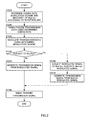
- radio communication apparatus 100 of this embodiment that is, a flow of the series of signal processing in a radio communication method according to the present invention will be described using FIG.2.
- determining section 112 determines a coding rate upon turbo encoding section 111 performs turbo encoding processing on transmission data, a modulation scheme at modulating section 113 for modulating the transmission data subjected to turbo encoding processing, and whether or not to perform modulation diversity processing on the modulated signal at modulation diversity processing section 120.
- determining section 112 makes decisions according to the following "table 1".
- determining section 112 reports the determined predetermined coding rate to turbo encoding section 111 or reports the determined modulation scheme to modulating section 113, and instructs switching section 114 to input the modulated signal to modulation diversity processing section 120 when the modulated signal is determined to be subjected to "Mod Div".
- determining section 112 instructs switching section 114 to input the modulated signal to S/P section 133.
- turbo encoding section 111 performs turbo encoding processing on the transmission data at the predetermined coding rate determined by determining section 112 in step ST210.
- step ST230 modulating section 113 modulates transmission data subjected to turbo encoding processing using the modulation scheme determined by determining section 112 in step ST120 and generates a modulated signal.
- step ST240 switching section 114 inputs the modulated signal to modulation diversity processing section 120 when the modulated signal is to be subjected to Mod Div and inputs the modulated signal to S/P section 133 when the modulated signal is not to be subjected to Mod Div, according to the instruction of determining section 112 in step ST210.
- determining section 112 determines in step ST210 to subject the modulated signal to Mod Div
- the flow proceeds to step ST240, and the processing of step ST260 is carried out.
- step ST240 determines in step ST210 not to subject the modulated signal to Mod Div
- the flow proceeds to step ST240, and the processing of step ST250 is carried out.
- step ST250 S/P section 133 and IFFT section 134 generate a transmission signal from the modulated signal.
- step ST260 modulation diversity processing section 120 generates a signal modulated using a modulation diversity technique from the modulated signal.
- step ST270 S/P section 133 and IFFT section 134 generate a transmission signal from the signal modulated using a modulation diversity technique.
- radio transmitting section 135 radio transmits a transmission signal generated from one of the modulated signal and the signal modulated using a modulation diversity technique to the radio communication apparatus on the communicating party side (not shown).
- FIG.3 illustrates operation of determining section 112.
- determining section 112 reports to modulating section 113 so as to modulate transmission data subjected to turbo encoding processing at a predetermined coding rate using BPSK and generate a modulated signal, and reports to switching section 114 so as to input this generated modulated signal to modulation diversity processing section 120. Therefore, in this embodiment, when the reception SNR is low, the transmission data is BPSK-modulated at modulating section 113, and a transmission signal is always generated from the modulated signal subjected to modulation diversity processing at a transmitting section of S/P section 133, or the like.
- determining section 112 reports to modulating section 113 so as to modulate transmission data subjected to turbo encoding processing using QPSK and generate a modulated signal, and reports to switching section 114 so as to input this generated modulated signal to S/P section 133.
- determining section 112 reports to modulating section 113 so as to modulate transmission data subjected to turbo encoding processing using QPSK and generate a modulated signal, and reports to switching section 114 so as to input this generated modulated signal to modulation diversity processing section 120.
- determining section 112 reports to modulating section 113 so as to modulate transmission data subjected to turbo encoding processing using 16QAM and generate a modulated signal, and reports to switching section 114 so as to input this generated modulated signal to S/P section 133.
- determining section 112 reports to modulating section 113 so as to modulate transmission data subjected to turbo encoding processing using 16QAM and generate a modulated signal, and reports to switching section 114 so as to input this generated modulated signal to modulation diversity processing section 120.
- determining section 112 determines a modulation scheme upon generation of a modulated signal and the necessity of modulation diversity processing upon generation of a transmission signal, according to the level of the inputted reception SNR, so that it is possible to make a transmission rate of a transmission signal higher by selecting the optimal modulation scheme for the current channel environment, and effectively prevent error correction performance at the radio communication apparatus on the communicating party side from decreasing by performing modulation diversity processing.
- Radio communication apparatus 100 of one embodiment of the present invention may be applied and modified as described below.
- turbo encoding section 111 performs turbo encoding processing on the transmission data
- present invention is by no means limited to this, and, for example, radio communication apparatus 100 may also perform other channel coding processing such as, for example, convolution encoding processing on the transmission data.
- the reception SNR inputted to determining section 112 is measured by a radio communication apparatus on the communicating party side (not shown) and returned as feedback information, but the present invention is by no means limited to this, and, for example, the reception SNR inputted to determining section 112 may also be measured based on a pilot signal received by radio communication apparatus 100.
- the radio communication apparatus on the communicating party side it is not necessary for the radio communication apparatus on the communicating party side to return feedback information to radio communication apparatus 100, so that it is possible to reduce the amount of signal processing for generating feedback information, transmit communication data in place of the feedback information, and thereby improve a transmission rate.
- determining section 112 determines a modulation scheme at modulating section 113 according to the level of the inputted reception SNR, but the present invention is by no means limited to this, and, for example, the coding rate at turbo encoding section 111 and the modulation scheme at modulating section 113 may be fixed in advance. By this means, it is not necessary to make a report to turbo encoding section 111 and modulating section 113 from determining section 112, so that it is possible to reduce internal traffic in radio communication apparatus 100.
- turbo encoding section 111 it is also possible to make a plurality of encoding rates at turbo encoding section 111 correspond to one modulation scheme atmodulating section 113.
- determining section 112 determines a modulation scheme for modulating transmission data at modulating section 113 and a coding rate when turbo encoding section 111 performs channel coding processing on transmission data, according to the level of the inputted reception SNR, and determines whether the transmission signal is generated from the modulated signal or the signal modulated using a modulation diversity technique at S/P section 133 according to the determined modulation scheme and coding rate.
- determining section 112 determines the necessity of modulation diversity processing in QPSK and 16QAM using 2 dB and 10 dB as threshold values for the inputted reception SNR, but the present invention is by no means limited to this.
- determining section 112 it is also possible for determining section 112 to acquire fluctuation information of reception power with a reception SNR as feedback information, monitor fluctuation of the reception power based on fluctuation information of this reception power, and increase the threshold value of QPSK and 16QAM, that is, higher than 2 dB or 10 dB, when the fluctuation of the reception power is large, while, on the other hand, lowering the threshold value of QPSK or 16QAM, that is, lower than 2 dB or 10 dB, when the fluctuation of the reception power is small.
- determining section 112 monitors reception power of each subcarrier based on the feedback information, and, when a difference of reception power between subcarriers is small (upper part of FIG.
- the threshold value of QPSK is lowered from 2 dB to 1 dB, while on the other hand, the threshold value of QPSK is increased from 2 dB to 4 dB when the difference of reception power between subcarriers is large (lower part of FIG.5).
- the present invention is by no means limited to this, and the threshold value for the reception SNR may also be set appropriately according to the channel environment and reception quality required at the radio communication system.
- radio communication apparatus and radio communication method of the present invention are by no means limited to the above-described embodiment, and various modifications thereof are possible.
- the radio communication apparatus can also be provided in a communication terminal apparatus and a base station apparatus in a mobile communication system using an OFDM scheme, or the like, and it is thereby possible to provide a communication terminal apparatus, a base station apparatus and a mobile communication system that have the same operation effects as those described above.
- the present invention can also be implemented as software.
- a radio communication method algorithm according to the present invention in a programming language, storing this program in a memory and making an information processing section execute this program, it is possible to implement the same function as the radio communication apparatus of the present invention.
- each function block used to explain the above-described embodiments is typically implemented as an LSI constituted by an integrated circuit. These may be individual chips or may partially or totally contained on a single chip.
- each function block is described as an LSI, but this may also be referred to as "IC”, “system LSI”, “super LSI”, “ultra LSI” depending on differing extents of integration.
- circuit integration is not limited to LSI's, and implementation using dedicated circuitry or general purpose processors is also possible.
- LSI manufacture utilization of a programmable FPGA (Field Programmable Gate Array) or a reconfigurable processor in which connections and settings of circuit cells within an LSI can be reconfigured is also possible.
- FPGA Field Programmable Gate Array
- the radio communication apparatus and radio communication method of the present invention provide an advantage of preventing error correction performance at a radio communication apparatus on a receiving side from decreasing even when a channel environment is poor and reception quality of a received signal is low, and are suitable for use in high-speed radio communication systems, or the like using multicarrier signals.
Landscapes
- Engineering & Computer Science (AREA)
- Signal Processing (AREA)
- Computer Networks & Wireless Communication (AREA)
- Quality & Reliability (AREA)
- Artificial Intelligence (AREA)
- Physics & Mathematics (AREA)
- Probability & Statistics with Applications (AREA)
- Radio Transmission System (AREA)
- Mobile Radio Communication Systems (AREA)
- Detection And Prevention Of Errors In Transmission (AREA)
Abstract
Description
- The present invention relates to a radio communication apparatus and a radio communication method for implementing modulation diversity processing on transmission data.
- In recent years, multicarrier communication apparatuses using an OFDM (Orthogonal Frequency Division Multiplexing) scheme draw attention as apparatuses achieving high-speed radio transmission, because such communication apparatuses have resistance to multipath and fading and realize high-quality communication. Further, in multicarrier communication, it is possible to further improve communication quality by applying a technique referred to as modulation and demodulation using a modulation diversity technique or simply as modulation diversity (for example, refer to non-patent document 1).
Non-patent document 01 : 03 AMGPP TSG RAN WG1 #31 R1-030156 "Modulation diversity for OFDM" - However, in a conventional radio communication system where modulation diversity processing (also referred to as "Mod Div") is performed on transmission data subjected to channel coding processing such as turbo coding, when a channel environment is poor, and reception quality of a received signal, for example, a reception SNR (Signal-to-Noise Ratio) is low, there is a problem that error correction performance decreases at a radio communication apparatus on a receiving side as a result of performing modulation diversity processing on transmission data at a radio communication apparatus on a transmitting side.
- It is therefore an object of the present invention to provide a radio communication apparatus on a transmitting side and radio communication method capable of suppressing decrease in error correction performance at a radio communication apparatus on a receiving side even when reception quality of a received signal is low due to a poor channel environment.
- A radio communication apparatus of the present invention adopts a configuration including: an encoding section that performs channel coding on transmission data; a modulating section that modulates the channel coded transmission data using a determined scheme and generates a modulated signal; a modulation diversity processing section that generates a signal modulated using a modulation diversity technique from the generated modulated signal; a transmitting section that generates a transmission signal from one of the modulated signal and the signal modulated using a modulation diversity technique and radio transmits the generated transmission signal; and a determining section that determines whether the transmission signal is generated from the modulated signal or the signal modulated using a modulation diversity technique at the transmitting section, according to a channel environment of the radio transmitted transmission signal.
- According to the present invention, whether a transmission signal is generated from a modulated signal or generated from a signal modulated using a modulation diversity technique is determined according to a channel environment of the transmission signal to be radio transmitted, so that it is possible to suppress decrease in error correction performance of a radio communication apparatus on a receiving side even when reception quality of the received signal (radio transmitted transmission signal) is poor due to a poor channel environment.
- Further, according to the present invention, a modulation scheme for modulating transmission data and generating a modulated signal, and whether the transmission signal is generated from a modulated signal or a signal modulated using a modulation diversity technique, is determined according to a channel environment of the transmission signal to be radio transmitted, so that it is possible to make a transmission rate of the transmission signal highest by selecting an optimum modulation scheme for a current channel environment, and effectively suppress decrease in the error correction performance of a radio communication apparatus on a receiving side.
-
- FIG.1 is a block diagram showing the main configuration of a radio communication apparatus according to one embodiment of the present invention;
- FIG.2 is a flowchart showing a series of signal processing in a radio communication method according to one embodiment of the present invention;
- FIG.3 illustrates operation of a determining section of one embodiment of the present invention;
- FIG.4 illustrates an application example of one embodiment of the present invention;
- FIG.5 further illustrates an application example of one embodiment of the present invention; and
- FIG.6 illustrates an outline of modulation and demodulation using a modulation diversity technique.
- One embodiment of the present invention will be described in detail hereinafter with reference to the accompanying drawings.
- First, modulation and demodulation using a modulation diversity technique will be simply described using FIG. 6. In the example shown in FIG. 6, transmission data is modulated using QPSK (Quadrature Phase Shift Keying). As shown in the upper part of FIG.6, a radio communication apparatus on a transmitting side first rotates a phase of symbols mapped to an IQ plane by a predetermined angle. Next, the radio communication apparatus on the transmitting side interleaves an Ich component and Qch component using different uniform or random interleavers for Ich and Qch. As shown in the middle part of FIG.6, the signal subjected to Inverse Fast Fourier Transformation (IFFT) is then such that an Ich component and Qch component of the symbol before interleaving are allocated to different subcarriers. In the case of the middle part of FIG.6, the Ich component is allocated to subcarrier B, and the Qch component is allocated to subcarrier A.
- On the other hand, the radio communication apparatus on the receiving side extracts the Ich component and Qch component superimposed on the subcarriers by first carrying out Fast Fourier Transformation (FFT). Next, the original arrangement of Ich and Qch is restored by carrying out de-interleaving. Received data is then obtained by carrying out de-mapping processing based on the restored constellation of Ich and Qch.
- Here, when subcarrier A is a good channel condition, and subcarrier B is a poor channel condition, as shown in the lower part of FIG.6, the constellation is shifted to the Qch axis. By this means, it is possible to maintain a signal point distance on the constellation at a relatively long, and restore bits in a packet accurately and averagely upon de-mapping. In this way, with modulation and demodulation using a modulation diversity technique, it is possible to obtain the same effects as spreading reception SNR (Signal-to-Noise Ratio) in a subcarrier direction and performing correction even when fading fluctuation occurs in each subcarrier due to multipath fading. As a result, the modulated symbol receives fluctuation as if the signal is transmitted on an AWGN (Additive White Gaussian Noise) communication path, and the diversity gain can thus be obtained.
- FIG.1 is a block diagram showing a main configuration of
radio communication apparatus 100 according to one embodiment of the present invention.Radio communication apparatus 100 radio transmits transmission signals comprised of signals modulated using a modulation diversity technique, and hasturbo encoding section 111, determiningsection 112, modulatingsection 113,switching section 114, modulationdiversity processing section 120, S/P section 133, IFFTsection 134,radio transmitting section 135 andantenna 136. Further, modulationdiversity processing section 120 hasphase rotating section 121,IQ separating section 122,interleaver 123 andIQ combining section 124. -
Turbo encoding section 111 performs turbo encoding processing on transmission data inputted from a data generating section (not shown) so as to obtain a predetermined coding rate determined by determiningsection 112 according to a current channel environment, and inputs transmission data subjected to turbo encoding processing to modulatingsection 113. - Determining
section 112 receives reception SNR indicating the current channel environment and determines a coding rate upon channel coding processing of the transmission data, a modulating scheme for modulating transmission data subjected to channel coding processing and whether or not to perform modulation diversity processing on the modulated signal.Determiningsection 112 reports the determined coding rate and modulation scheme toturbo encoding section 111 and modulatingsection 113, respectively, and instructsswitching section 114 on an input destination of the modulated signal . The reception SNR inputted to determiningsection 112 is measured by a radio communication apparatus on a communicating party side (not shown), and it is assumed that the reception SNR is returned from the radio communication apparatus on the communicating party side as feedback information. It is assumed thatradio communication apparatus 100 also has a radio receiving section (not shown) that receives a radio signal containing this feedback information viaantenna 136. Further, operation of determiningsection 112 will be described later. - Modulating
section 113 modulates the transmission data inputted fromturbo encoding section 111 using the modulation scheme reported from determiningsection 112, for example, BPSK (Binariphase Phase Shift Keying), QPSK (Quadrature Phase Shift Keying) or 16QAM (Quadrature Amplitude Modulation), and thereby generates a modulated signal where the transmission data is mapped to an IQ plane. Modulatingsection 113 inputs the generated modulated signal to switchingsection 114. - Switching
section 114 inputs the modulated signal inputted from modulatingsection 113 to either modulationdiversity processing section 120 or S/P section 133 according to the instruction from determiningsection 112. - At modulation
diversity processing section 120,phase rotating section 121 rotates the phase of the symbols of the modulated signal inputted from switchingsection 114 by just a predetermined angle as shown in the upper part of FIG.6. Symbols where the phase is rotated are separated into an Ich component and a Qch component byIQ separating section 122, and one of the Ich component and Qch component is transmitted tointerleaver 123, and the other is transmitted toIQ combining section 124. The Ich component or Qch component interleaved using the interleave pattern determined in advance byinterleaver 123 is transmitted toIQ combining section 124.IQ combining section 124 then restores a constellation by combining the Ich component and Qch component. Modulationdiversity processing section 120 then generates a signal modulated using a modulation diversity technique through a series of modulation diversity processing. Modulationdiversity processing section 120 then inputs the generated signal modulated using a modulation diversity technique to S/P section 133. - S/
P section 133 converts one of a modulated signal inputted fromswitching section 114 and the signal which is modulated using a modulation diversity technique and inputted from modulationdiversity processing section 120 from a serial signal to a parallel signal, and inputs this parallel signal toIFFT section 134. - IFFT
section 134 performs publicly known IFFT processing on the parallel signal inputted from S/P section 133 to generate an OFDM signal and inputs the generated OFDM signal to radio transmittingsection 135. IFFTsection 134 allocates the Ich and Qch to different subcarriers as shown in the middle part of FIG.6 upon generation the OFDM signal. -
Radio transmitting section 135 inserts guard intervals into the OFDM signal inputted fromIFFT section 134 and performs frequency conversion processing, amplification processing, and the like . Then, the OFDM signal subjected to a series of radio transmission processing is radio transmitted to the radio communication apparatus on the communicating party side (not shown) viaantenna 136. - Therefore, in this embodiment, a "transmitting section" that is a matter to define the present invention includes an S/
P section 133, IFFTsection 134 andradio transmitting section 135. - Next, the main operation of
radio communication apparatus 100 of this embodiment, that is, a flow of the series of signal processing in a radio communication method according to the present invention will be described using FIG.2. - First, in step ST210, according to the level of the inputted reception SNR, determining
section 112 determines a coding rate uponturbo encoding section 111 performs turbo encoding processing on transmission data, a modulation scheme at modulatingsection 113 for modulating the transmission data subjected to turbo encoding processing, and whether or not to perform modulation diversity processing on the modulated signal at modulationdiversity processing section 120. In this embodiment, it is assumed that determiningsection 112 makes decisions according to the following "table 1". In step ST210, determiningsection 112 reports the determined predetermined coding rate toturbo encoding section 111 or reports the determined modulation scheme to modulatingsection 113, and instructsswitching section 114 to input the modulated signal to modulationdiversity processing section 120 when the modulated signal is determined to be subjected to "Mod Div". On the other hand, when the modulated signal is determined not to be subjected to "Mod Div", determiningsection 112 instructsswitching section 114 to input the modulated signal to S/P section 133. -
[Table 1] Reception SNR Modulation scheme Necessity of Mod Div -10 to -2 dB BPSK Subject to Mod Div -2 to 2 dB QPSK No Mod Div 2 to 6 dB Subject to Mod Div 6 to 10 dB 16QAM No Mod Div 10 to 15 dB Subject to Mod Div - Subsequently, in step ST220,
turbo encoding section 111 performs turbo encoding processing on the transmission data at the predetermined coding rate determined by determiningsection 112 in step ST210. - Next, in step ST230, modulating
section 113 modulates transmission data subjected to turbo encoding processing using the modulation scheme determined by determiningsection 112 in step ST120 and generates a modulated signal. - In step ST240, switching
section 114 inputs the modulated signal to modulationdiversity processing section 120 when the modulated signal is to be subjected to Mod Div and inputs the modulated signal to S/P section 133 when the modulated signal is not to be subjected to Mod Div, according to the instruction of determiningsection 112 in step ST210. When determiningsection 112 determines in step ST210 to subject the modulated signal to Mod Div, the flow proceeds to step ST240, and the processing of step ST260 is carried out. On the other hand, when determiningsection 112 determines in step ST210 not to subject the modulated signal to Mod Div, the flow proceeds to step ST240, and the processing of step ST250 is carried out. - Next, in step ST250, S/
P section 133 andIFFT section 134 generate a transmission signal from the modulated signal. - On the other hand, in step ST260, modulation
diversity processing section 120 generates a signal modulated using a modulation diversity technique from the modulated signal. - Next, in step ST270, S/
P section 133 andIFFT section 134 generate a transmission signal from the signal modulated using a modulation diversity technique. - Subsequently, in step ST280,
radio transmitting section 135 radio transmits a transmission signal generated from one of the modulated signal and the signal modulated using a modulation diversity technique to the radio communication apparatus on the communicating party side (not shown). - FIG.3 illustrates operation of determining
section 112. In this embodiment, as shown in FIG.3, when the inputted reception SNR is greater than -10 dB and less than -2 dB, determiningsection 112 reports to modulatingsection 113 so as to modulate transmission data subjected to turbo encoding processing at a predetermined coding rate using BPSK and generate a modulated signal, and reports to switchingsection 114 so as to input this generated modulated signal to modulationdiversity processing section 120. Therefore, in this embodiment, when the reception SNR is low, the transmission data is BPSK-modulated at modulatingsection 113, and a transmission signal is always generated from the modulated signal subjected to modulation diversity processing at a transmitting section of S/P section 133, or the like. - Further, in this embodiment, as shown in FIG.3, when the inputted reception SNR is greater than -2 dB and less than 2 dB, determining
section 112 reports to modulatingsection 113 so as to modulate transmission data subjected to turbo encoding processing using QPSK and generate a modulated signal, and reports to switchingsection 114 so as to input this generated modulated signal to S/P section 133. - Further, in this embodiment, as shown in FIG.3, when the inputted reception SNR is greater than 2 dB and less than 6 dB, determining
section 112 reports to modulatingsection 113 so as to modulate transmission data subjected to turbo encoding processing using QPSK and generate a modulated signal, and reports to switchingsection 114 so as to input this generated modulated signal to modulationdiversity processing section 120. - Moreover, in this embodiment, as shown in FIG.3, when the inputted reception SNR is greater than 6 dB and less than 10 dB, determining
section 112 reports to modulatingsection 113 so as to modulate transmission data subjected to turbo encoding processing using 16QAM and generate a modulated signal, and reports to switchingsection 114 so as to input this generated modulated signal to S/P section 133. - Further, in this embodiment, as shown in FIG.3, when the inputted reception SNR is greater than 10 dB, determining
section 112 reports to modulatingsection 113 so as to modulate transmission data subjected to turbo encoding processing using 16QAM and generate a modulated signal, and reports to switchingsection 114 so as to input this generated modulated signal to modulationdiversity processing section 120. - In this way, according to this embodiment, determining
section 112 determines a modulation scheme upon generation of a modulated signal and the necessity of modulation diversity processing upon generation of a transmission signal, according to the level of the inputted reception SNR, so that it is possible to make a transmission rate of a transmission signal higher by selecting the optimal modulation scheme for the current channel environment, and effectively prevent error correction performance at the radio communication apparatus on the communicating party side from decreasing by performing modulation diversity processing. -
Radio communication apparatus 100 of one embodiment of the present invention may be applied and modified as described below. - In one embodiment of the present invention, the case has been described where
turbo encoding section 111 performs turbo encoding processing on the transmission data, but the present invention is by no means limited to this, and, for example,radio communication apparatus 100 may also perform other channel coding processing such as, for example, convolution encoding processing on the transmission data. - Further, in one embodiment of the present invention, the case has been described where the reception SNR inputted to determining
section 112 is measured by a radio communication apparatus on the communicating party side (not shown) and returned as feedback information, but the present invention is by no means limited to this, and, for example, the reception SNR inputted to determiningsection 112 may also be measured based on a pilot signal received byradio communication apparatus 100. By this means, it is not necessary for the radio communication apparatus on the communicating party side to return feedback information toradio communication apparatus 100, so that it is possible to reduce the amount of signal processing for generating feedback information, transmit communication data in place of the feedback information, and thereby improve a transmission rate. - Further, in one embodiment of the present invention, the case has been described where determining
section 112 determines a modulation scheme at modulatingsection 113 according to the level of the inputted reception SNR, but the present invention is by no means limited to this, and, for example, the coding rate atturbo encoding section 111 and the modulation scheme at modulatingsection 113 may be fixed in advance. By this means, it is not necessary to make a report toturbo encoding section 111 and modulatingsection 113 from determiningsection 112, so that it is possible to reduce internal traffic inradio communication apparatus 100. - Further, in the present invention, for example, it is also possible to make a plurality of encoding rates at
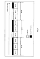
turbo encoding section 111 correspond to one modulationscheme atmodulating section 113. Specifically, as shown in FIG.4, it is also possible to assign BPSK, QPSK and 16QAM as modulation schemes in an ascending order of the reception SNR inputted to determiningsection 112 and make three coding rates R = 1/3, 1/2, 3/4, in that order correspond to the modulation schemes. In this case, determiningsection 112 determines a modulation scheme for modulating transmission data at modulatingsection 113 and a coding rate whenturbo encoding section 111 performs channel coding processing on transmission data, according to the level of the inputted reception SNR, and determines whether the transmission signal is generated from the modulated signal or the signal modulated using a modulation diversity technique at S/P section 133 according to the determined modulation scheme and coding rate. - Further, in this embodiment, the case has been described where determining
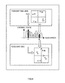
section 112 determines the necessity of modulation diversity processing in QPSK and 16QAM using 2 dB and 10 dB as threshold values for the inputted reception SNR, but the present invention is by no means limited to this. For example, it is also possible for determiningsection 112 to acquire fluctuation information of reception power with a reception SNR as feedback information, monitor fluctuation of the reception power based on fluctuation information of this reception power, and increase the threshold value of QPSK and 16QAM, that is, higher than 2 dB or 10 dB, when the fluctuation of the reception power is large, while, on the other hand, lowering the threshold value of QPSK or 16QAM, that is, lower than 2 dB or 10 dB, when the fluctuation of the reception power is small. Specifically, as shown in FIG.5, determiningsection 112 monitors reception power of each subcarrier based on the feedback information, and, when a difference of reception power between subcarriers is small (upper part of FIG. 5), the threshold value of QPSK is lowered from 2 dB to 1 dB, while on the other hand, the threshold value of QPSK is increased from 2 dB to 4 dB when the difference of reception power between subcarriers is large (lower part of FIG.5). - Further, in this embodiment, the case has been described where 2 dB and 10 dB are used as threshold values for determining the necessity of modulation diversity processing for the reception SNR inputted to determining
section 112, but the present invention is by no means limited to this, and the threshold value for the reception SNR may also be set appropriately according to the channel environment and reception quality required at the radio communication system. - The embodiment of the present invention has been described.
- The radio communication apparatus and radio communication method of the present invention are by no means limited to the above-described embodiment, and various modifications thereof are possible.
- The radio communication apparatus according to the present invention can also be provided in a communication terminal apparatus and a base station apparatus in a mobile communication system using an OFDM scheme, or the like, and it is thereby possible to provide a communication terminal apparatus, a base station apparatus and a mobile communication system that have the same operation effects as those described above.
- The case has been described here as an example where the present invention is configured with hardware, but the present invention can also be implemented as software. For example, by describing a radio communication method algorithm according to the present invention in a programming language, storing this program in a memory and making an information processing section execute this program, it is possible to implement the same function as the radio communication apparatus of the present invention.
- Furthermore, each function block used to explain the above-described embodiments is typically implemented as an LSI constituted by an integrated circuit. These may be individual chips or may partially or totally contained on a single chip.
- Here, each function block is described as an LSI, but this may also be referred to as "IC", "system LSI", "super LSI", "ultra LSI" depending on differing extents of integration.
- Further, the method of circuit integration is not limited to LSI's, and implementation using dedicated circuitry or general purpose processors is also possible. After LSI manufacture, utilization of a programmable FPGA (Field Programmable Gate Array) or a reconfigurable processor in which connections and settings of circuit cells within an LSI can be reconfigured is also possible.
- Further, if integrated circuit technology comes out to replace LSI's as a result of the advancement of semiconductor technology or a derivative other technology, it is naturally also possible to carry out function block integration using this technology. Application in biotechnology is also possible.
- The present application is based on
Japanese Patent Application Laid-Open No.2005-014771, filed on January 21, 2005 - The radio communication apparatus and radio communication method of the present invention provide an advantage of preventing error correction performance at a radio communication apparatus on a receiving side from decreasing even when a channel environment is poor and reception quality of a received signal is low, and are suitable for use in high-speed radio communication systems, or the like using multicarrier signals.
Claims (9)
- A radio communication apparatus comprising:an encoding section that performs channel coding on transmission data;a modulating section that modulates the channel coded transmission data using a determined scheme and generates a modulated signal;a modulation diversity processing section that generates a signal modulated using a modulation diversity technique from the generated modulated signal;a transmitting section that generates a transmission signal from one of the modulated signal and the signal modulated using a modulation diversity technique and radio transmits the generated transmission signal; anda determining section that determines whether the transmission signal is generated from the modulated signal or the signal modulated using a modulation diversity technique at the transmitting section, according to a channel environment of the radio transmitted transmission signal.
- The radio communication apparatus according to claim 1, wherein the determining section determines a modulation scheme for modulating the transmission data at the modulating section and whether the transmission signal is generated from the modulated signal or the signal modulated using a modulation diversity technique at the transmitting section, according to the channel environment of the radio transmitted transmission signal .
- The radio communication apparatus according to claim 2, wherein when reception quality of the transmission signal is less than a first threshold value, the determining section determines to modulate the transmission data using BPSK at the modulating section and generate the transmission signal from the signal modulated using a modulation diversity technique at the transmitting section.
- The radio communication apparatus according to claim 2, wherein:when reception quality of the transmission signal is less than a first threshold value, the determining section determines to modulate the transmission data using BPSK at the modulating section and generate the transmission signal from the signal modulated using a modulation diversity technique at the transmitting section;when the reception quality of the transmission signal is equal to or greater than the first threshold value and less than a second threshold value, the determining section determines to modulate the transmission data using QPSK at the modulating section and generate the transmission signal from the modulated signal at the transmitting section; andwhen the reception quality of the transmission signal is equal to or greater than the second threshold value and less than a third threshold value, the determining section determines to modulate the transmission data using QPSK at the modulating section and generate the transmission signal from the signal modulated using a modulation diversity technique at the transmitting section.
- The radio communication apparatus according to claim 2, wherein:when reception quality of the transmission signal is less than a first threshold value, the determining section determines to modulate the transmission data using BPSK at the modulating section and generate the transmission signal from the signal modulated using a modulation diversity technique at the transmitting section;when the reception quality of the transmission signal is equal to or greater than the first threshold value and less than a second threshold value, the determining section determines to modulate the transmission data using QPSK at the modulating section and generate the transmission signal from the modulated signal at the transmitting section;when the reception quality of the transmission signal is equal to or greater than the second threshold value and less than a third threshold value, the determining section determines to modulate the transmission data using QPSK at the modulating section and generate the transmission signal from the signal modulated using a modulation diversity technique at the transmitting section;when the reception quality of the transmission signal is equal to or greater than the third threshold value and less than a fourth threshold value, the determining section determines to modulate the transmission data using 16QAM at the modulating section and generate the transmission signal from the modulated signal at the transmitting section; andwhen reception quality of the transmission signal is equal to or greater than a fourth threshold value, the determining section determines to modulate the transmission data using 16QAM at the modulating section and generate the transmission signal at the transmitting section from the signal modulated using a modulation diversity technique.
- The radio communication apparatus according to claim 4, further comprising a receiving section that receives a radio signal including reception quality and fluctuation information of reception power for the transmission signal measured by another radio communication apparatus receiving the radio transmitted transmission signal,
wherein the determining section monitors fluctuation of the reception power based on fluctuation information of reception power for the received transmission signal and increases the second threshold value when fluctuation of the reception power becomes larger, and lowers the second threshold value when fluctuation of the reception power becomes smaller. - A communication terminal apparatus comprising the radio communication apparatus according to claim 1.
- A base station apparatus comprising the radio communication apparatus according to claim 1.
- A radio communication method comprising:an encoding step of performing channel coding on transmission data;a modulating step of modulating the channel coded transmission data using a determined scheme and generating a modulated signal;a modulation diversity processingstepofgenerating a signal modulated using a modulation diversity technique from the generated modulated signal;a transmitting step of generating a transmission signal from one of the modulated signal and the signal modulated using a modulation diversity technique and radio transmitting the generated transmission signal; anda determining step of determining whether the transmission signal is generated from the modulated signal or the signal modulated using a modulation diversity technique in the transmitting step according to a channel environment of the radio transmitted transmission signal.
Applications Claiming Priority (2)
| Application Number | Priority Date | Filing Date | Title |
|---|---|---|---|
| JP2005014771 | 2005-01-21 | ||
| PCT/JP2006/300755 WO2006077933A1 (en) | 2005-01-21 | 2006-01-19 | Wireless communication apparatus and wireless communication method |
Publications (3)
| Publication Number | Publication Date |
|---|---|
| EP1830503A1 true EP1830503A1 (en) | 2007-09-05 |
| EP1830503A4 EP1830503A4 (en) | 2013-07-31 |
| EP1830503B1 EP1830503B1 (en) | 2015-12-30 |
Family
ID=36692318
Family Applications (1)
| Application Number | Title | Priority Date | Filing Date |
|---|---|---|---|
| EP06712001.4A Expired - Lifetime EP1830503B1 (en) | 2005-01-21 | 2006-01-19 | Wireless communication apparatus and wireless communication method |
Country Status (5)
| Country | Link |
|---|---|
| US (1) | US7738592B2 (en) |
| EP (1) | EP1830503B1 (en) |
| JP (1) | JP4841440B2 (en) |
| CN (1) | CN101107801B (en) |
| WO (1) | WO2006077933A1 (en) |
Families Citing this family (32)
| Publication number | Priority date | Publication date | Assignee | Title |
|---|---|---|---|---|
| US5031858A (en) * | 1989-11-20 | 1991-07-16 | Bell Helicopter Textron, Inc. | Apparatus and method for folding and locking rotor blades |
| JP4641233B2 (en) * | 2005-09-14 | 2011-03-02 | ルネサスエレクトロニクス株式会社 | Demodulator and demodulation method |
| US8072874B2 (en) * | 2007-09-11 | 2011-12-06 | The Directv Group, Inc. | Method and system for switching to an engineering signal processing system from a production signal processing system |
| CN101543077B (en) * | 2007-01-31 | 2011-01-19 | 索尼株式会社 | Information processing device and method |
| US8973058B2 (en) | 2007-09-11 | 2015-03-03 | The Directv Group, Inc. | Method and system for monitoring and simultaneously displaying a plurality of signal channels in a communication system |
| US8424044B2 (en) * | 2007-09-11 | 2013-04-16 | The Directv Group, Inc. | Method and system for monitoring and switching between a primary encoder and a back-up encoder in a communication system |
| US9756290B2 (en) * | 2007-09-11 | 2017-09-05 | The Directv Group, Inc. | Method and system for communicating between a local collection facility and a remote facility |
| US8170069B2 (en) | 2007-09-11 | 2012-05-01 | The Directv Group, Inc. | Method and system for processing signals from a local collection facility at a signal processing facility |
| US9313457B2 (en) | 2007-09-11 | 2016-04-12 | The Directv Group, Inc. | Method and system for monitoring a receiving circuit module and controlling switching to a back-up receiving circuit module at a local collection facility from a remote facility |
| US9300412B2 (en) | 2007-09-11 | 2016-03-29 | The Directv Group, Inc. | Method and system for operating a receiving circuit for multiple types of input channel signals |
| US8356321B2 (en) | 2007-09-11 | 2013-01-15 | The Directv Group, Inc. | Method and system for monitoring and controlling receiving circuit modules at a local collection facility from a remote facility |
| US8479234B2 (en) * | 2007-09-12 | 2013-07-02 | The Directv Group, Inc. | Method and system for monitoring and controlling a local collection facility from a remote facility using an asynchronous transfer mode (ATM) network |
| US7861270B2 (en) | 2007-09-12 | 2010-12-28 | The Directv Group, Inc. | Method and system for controlling a back-up receiver and encoder in a local collection facility from a remote facility |
| US8988986B2 (en) * | 2007-09-12 | 2015-03-24 | The Directv Group, Inc. | Method and system for controlling a back-up multiplexer in a local collection facility from a remote facility |
| US8724635B2 (en) * | 2007-09-12 | 2014-05-13 | The Directv Group, Inc. | Method and system for controlling a back-up network adapter in a local collection facility from a remote facility |
| US9037074B2 (en) | 2007-10-30 | 2015-05-19 | The Directv Group, Inc. | Method and system for monitoring and controlling a local collection facility from a remote facility through an IP network |
| US9049354B2 (en) | 2007-10-30 | 2015-06-02 | The Directv Group, Inc. | Method and system for monitoring and controlling a back-up receiver in local collection facility from a remote facility using an IP network |
| US9049037B2 (en) | 2007-10-31 | 2015-06-02 | The Directv Group, Inc. | Method and system for monitoring and encoding signals in a local facility and communicating the signals between a local collection facility and a remote facility using an IP network |
| US8077706B2 (en) * | 2007-10-31 | 2011-12-13 | The Directv Group, Inc. | Method and system for controlling redundancy of individual components of a remote facility system |
| US9762973B2 (en) | 2008-11-04 | 2017-09-12 | The Directv Group, Inc. | Method and system for operating a receiving circuit module to encode a channel signal into multiple encoding formats |
| US9831971B1 (en) | 2011-04-05 | 2017-11-28 | The Directv Group, Inc. | Method and system for operating a communication system encoded into multiple independently communicated encoding formats |
| US9071289B2 (en) * | 2012-04-23 | 2015-06-30 | Cambridge Silicon Radio Limited | Transceiver supporting multiple modulation schemes |
| CN106612156A (en) * | 2015-10-26 | 2017-05-03 | 中国船舶重工集团公司第七二二研究所 | Data frame wireless transmission method and device |
| WO2019053165A1 (en) * | 2017-09-15 | 2019-03-21 | Telefonaktiebolaget Lm Ericsson (Publ) | Code-rate-dependent modulation techniques |
| US11031961B2 (en) | 2019-07-16 | 2021-06-08 | Microsoft Technology Licensing, Llc | Smart symbol changes for optimization of communications using error correction |
| US11063696B2 (en) | 2019-07-16 | 2021-07-13 | Microsoft Technology Licensing, Llc | Increasing average power levels to reduce peak-to-average power levels using error correction codes |
| US10911284B1 (en) | 2019-07-16 | 2021-02-02 | Microsoft Technology Licensing, Llc | Intelligent optimization of communication systems utilizing error correction |
| US11075656B2 (en) * | 2019-07-16 | 2021-07-27 | Microsoft Technology Licensing, Llc | Bit error reduction of communication systems using error correction |
| US11044044B2 (en) | 2019-07-16 | 2021-06-22 | Microsoft Technology Licensing, Llc | Peak to average power ratio reduction of optical systems utilizing error correction |
| US11086719B2 (en) | 2019-07-16 | 2021-08-10 | Microsoft Technology Licensing, Llc | Use of error correction codes to prevent errors in neighboring storage |
| US11172455B2 (en) | 2019-07-16 | 2021-11-09 | Microsoft Technology Licensing, Llc | Peak to average power output reduction of RF systems utilizing error correction |
| US10911141B1 (en) | 2019-07-30 | 2021-02-02 | Microsoft Technology Licensing, Llc | Dynamically selecting a channel model for optical communications |
Family Cites Families (7)
| Publication number | Priority date | Publication date | Assignee | Title |
|---|---|---|---|---|
| EP0975118B1 (en) * | 1998-07-24 | 2007-05-09 | Matsushita Electric Industrial Co., Ltd. | CDMA radio communication system and method |
| JP2003101504A (en) * | 2001-09-21 | 2003-04-04 | Sony Corp | Transmission device and method, communication system, recording medium, and program |
| US7103325B1 (en) | 2002-04-05 | 2006-09-05 | Nortel Networks Limited | Adaptive modulation and coding |
| EP1355434B1 (en) * | 2002-04-19 | 2004-12-29 | Alcatel Alsthom Compagnie Generale D'electricite | A method for transmitting a signal between a terminal and a network component |
| US7289459B2 (en) * | 2002-08-07 | 2007-10-30 | Motorola Inc. | Radio communication system with adaptive interleaver |
| CN1836391A (en) * | 2003-07-14 | 2006-09-20 | 松下电器产业株式会社 | Multi-carrier transmitting device, multi-carrier receiving device and multi-carrier communication method |
| BRPI0414902A (en) * | 2003-09-30 | 2006-11-07 | Matsushita Electric Industrial Co Ltd | radio transmission apparatus, radio reception apparatus and radio transmission method |
-
2006
- 2006-01-19 JP JP2006553951A patent/JP4841440B2/en not_active Expired - Fee Related
- 2006-01-19 CN CN2006800027934A patent/CN101107801B/en not_active Expired - Fee Related
- 2006-01-19 WO PCT/JP2006/300755 patent/WO2006077933A1/en not_active Ceased
- 2006-01-19 EP EP06712001.4A patent/EP1830503B1/en not_active Expired - Lifetime
- 2006-01-19 US US11/814,125 patent/US7738592B2/en active Active
Also Published As
| Publication number | Publication date |
|---|---|
| CN101107801A (en) | 2008-01-16 |
| JP4841440B2 (en) | 2011-12-21 |
| US7738592B2 (en) | 2010-06-15 |
| WO2006077933A1 (en) | 2006-07-27 |
| EP1830503A4 (en) | 2013-07-31 |
| CN101107801B (en) | 2012-01-18 |
| EP1830503B1 (en) | 2015-12-30 |
| US20090022241A1 (en) | 2009-01-22 |
| JPWO2006077933A1 (en) | 2008-06-19 |
Similar Documents
| Publication | Publication Date | Title |
|---|---|---|
| US7738592B2 (en) | Wireless communication apparatus and wireless communication method | |
| US10686550B2 (en) | Radio transmission device and method | |
| JP3732830B2 (en) | Multicarrier transmission apparatus and multicarrier transmission method | |
| US8149949B2 (en) | Radio transmitter apparatus, radio receiver apparatus, and wireless communication system | |
| US8693585B2 (en) | Communication apparatus and communication method | |
| US8249181B2 (en) | Multi-carrier transmission device and multi-carrier transmission method | |
| CN1806307B (en) | Multi-carrier communication method and communication device thereof | |
| EP1811700A1 (en) | Communication apparatus, communication system, and communication method | |
| US20060221807A1 (en) | Multi-carrier transmitter apparatus, multi-carrier receiver apparatus and multi-carrier communication method | |
| US20040176033A1 (en) | Wireless communication system and transmit power and data rate control method therefor | |
| US20110261741A1 (en) | Transmission apparatus and method, and reception apparatus and method | |
| KR20060132786A (en) | Multicarrier communication device, multicarrier communication system and transmission power control method | |
| US20070047431A1 (en) | Radio transmission apparatus and peak power suppression method in multicarrier communication | |
| US9680683B2 (en) | Radio receiver apparatus and radio transmitter apparatus | |
| US7545873B2 (en) | Radio transmission apparatus, radio reception apparatus and radio transmission method | |
| US7856064B2 (en) | OFDM communication apparatus and OFDM communication method | |
| US20050229073A1 (en) | Transmitting device and transmitting method | |
| US8170136B2 (en) | Radio transmitting apparatus and radio transmitting method |
Legal Events
| Date | Code | Title | Description |
|---|---|---|---|
| PUAI | Public reference made under article 153(3) epc to a published international application that has entered the european phase |
Free format text: ORIGINAL CODE: 0009012 |
|
| 17P | Request for examination filed |
Effective date: 20070719 |
|
| AK | Designated contracting states |
Kind code of ref document: A1 Designated state(s): AT BE BG CH CY CZ DE DK EE ES FI FR GB GR HU IE IS IT LI LT LU LV MC NL PL PT RO SE SI SK TR |
|
| RIN1 | Information on inventor provided before grant (corrected) |
Inventor name: FUTAGI, SADAKI,MATSUSHITA ELECT. INDUSTRIAL CO.,LT Inventor name: MIYOSHI, KENICHI,MATSUSHITA ELECT. INDUSTRIAL CO., Inventor name: FUKUOKA, MASARUMATSUSHITA ELECT. INDUSTRIAL CO.,LT |
|
| DAX | Request for extension of the european patent (deleted) | ||
| RAP1 | Party data changed (applicant data changed or rights of an application transferred) |
Owner name: PANASONIC CORPORATION |
|
| A4 | Supplementary search report drawn up and despatched |
Effective date: 20130628 |
|
| RIC1 | Information provided on ipc code assigned before grant |
Ipc: H04L 5/00 20060101ALI20130624BHEP Ipc: H04J 11/00 20060101AFI20130624BHEP Ipc: H04L 27/26 20060101ALI20130624BHEP Ipc: H04B 7/26 20060101ALI20130624BHEP Ipc: H04L 1/00 20060101ALI20130624BHEP Ipc: H04L 27/34 20060101ALI20130624BHEP Ipc: H04L 1/02 20060101ALI20130624BHEP |
|
| 17Q | First examination report despatched |
Effective date: 20130711 |
|
| RAP1 | Party data changed (applicant data changed or rights of an application transferred) |
Owner name: PANASONIC INTELLECTUAL PROPERTY CORPORATION OF AME |
|
| GRAP | Despatch of communication of intention to grant a patent |
Free format text: ORIGINAL CODE: EPIDOSNIGR1 |
|
| INTG | Intention to grant announced |
Effective date: 20150708 |
|
| RIN1 | Information on inventor provided before grant (corrected) |
Inventor name: FUTAGI, SADAKI Inventor name: FUKUOKA, MASARU Inventor name: MIYOSHI, KENICHI |
|
| GRAS | Grant fee paid |
Free format text: ORIGINAL CODE: EPIDOSNIGR3 |
|
| GRAA | (expected) grant |
Free format text: ORIGINAL CODE: 0009210 |
|
| AK | Designated contracting states |
Kind code of ref document: B1 Designated state(s): AT BE BG CH CY CZ DE DK EE ES FI FR GB GR HU IE IS IT LI LT LU LV MC NL PL PT RO SE SI SK TR |
|
| REG | Reference to a national code |
Ref country code: GB Ref legal event code: FG4D |
|
| REG | Reference to a national code |
Ref country code: CH Ref legal event code: EP |
|
| REG | Reference to a national code |
Ref country code: AT Ref legal event code: REF Ref document number: 767885 Country of ref document: AT Kind code of ref document: T Effective date: 20160115 |
|
| REG | Reference to a national code |
Ref country code: IE Ref legal event code: FG4D |
|
| REG | Reference to a national code |
Ref country code: DE Ref legal event code: R096 Ref document number: 602006047593 Country of ref document: DE |
|
| REG | Reference to a national code |
Ref country code: LT Ref legal event code: MG4D |
|
| PG25 | Lapsed in a contracting state [announced via postgrant information from national office to epo] |
Ref country code: LT Free format text: LAPSE BECAUSE OF FAILURE TO SUBMIT A TRANSLATION OF THE DESCRIPTION OR TO PAY THE FEE WITHIN THE PRESCRIBED TIME-LIMIT Effective date: 20151230 |
|
| REG | Reference to a national code |
Ref country code: NL Ref legal event code: MP Effective date: 20151230 |
|
| REG | Reference to a national code |
Ref country code: AT Ref legal event code: MK05 Ref document number: 767885 Country of ref document: AT Kind code of ref document: T Effective date: 20151230 |
|
| PG25 | Lapsed in a contracting state [announced via postgrant information from national office to epo] |
Ref country code: SE Free format text: LAPSE BECAUSE OF FAILURE TO SUBMIT A TRANSLATION OF THE DESCRIPTION OR TO PAY THE FEE WITHIN THE PRESCRIBED TIME-LIMIT Effective date: 20151230 Ref country code: FI Free format text: LAPSE BECAUSE OF FAILURE TO SUBMIT A TRANSLATION OF THE DESCRIPTION OR TO PAY THE FEE WITHIN THE PRESCRIBED TIME-LIMIT Effective date: 20151230 Ref country code: BE Free format text: LAPSE BECAUSE OF NON-PAYMENT OF DUE FEES Effective date: 20160131 Ref country code: GR Free format text: LAPSE BECAUSE OF FAILURE TO SUBMIT A TRANSLATION OF THE DESCRIPTION OR TO PAY THE FEE WITHIN THE PRESCRIBED TIME-LIMIT Effective date: 20160331 Ref country code: LV Free format text: LAPSE BECAUSE OF FAILURE TO SUBMIT A TRANSLATION OF THE DESCRIPTION OR TO PAY THE FEE WITHIN THE PRESCRIBED TIME-LIMIT Effective date: 20151230 |
|
| PG25 | Lapsed in a contracting state [announced via postgrant information from national office to epo] |
Ref country code: NL Free format text: LAPSE BECAUSE OF FAILURE TO SUBMIT A TRANSLATION OF THE DESCRIPTION OR TO PAY THE FEE WITHIN THE PRESCRIBED TIME-LIMIT Effective date: 20151230 |
|
| PG25 | Lapsed in a contracting state [announced via postgrant information from national office to epo] |
Ref country code: IT Free format text: LAPSE BECAUSE OF FAILURE TO SUBMIT A TRANSLATION OF THE DESCRIPTION OR TO PAY THE FEE WITHIN THE PRESCRIBED TIME-LIMIT Effective date: 20151230 Ref country code: ES Free format text: LAPSE BECAUSE OF FAILURE TO SUBMIT A TRANSLATION OF THE DESCRIPTION OR TO PAY THE FEE WITHIN THE PRESCRIBED TIME-LIMIT Effective date: 20151230 Ref country code: CZ Free format text: LAPSE BECAUSE OF FAILURE TO SUBMIT A TRANSLATION OF THE DESCRIPTION OR TO PAY THE FEE WITHIN THE PRESCRIBED TIME-LIMIT Effective date: 20151230 |
|
| PG25 | Lapsed in a contracting state [announced via postgrant information from national office to epo] |
Ref country code: AT Free format text: LAPSE BECAUSE OF FAILURE TO SUBMIT A TRANSLATION OF THE DESCRIPTION OR TO PAY THE FEE WITHIN THE PRESCRIBED TIME-LIMIT Effective date: 20151230 Ref country code: IS Free format text: LAPSE BECAUSE OF FAILURE TO SUBMIT A TRANSLATION OF THE DESCRIPTION OR TO PAY THE FEE WITHIN THE PRESCRIBED TIME-LIMIT Effective date: 20160430 Ref country code: RO Free format text: LAPSE BECAUSE OF FAILURE TO SUBMIT A TRANSLATION OF THE DESCRIPTION OR TO PAY THE FEE WITHIN THE PRESCRIBED TIME-LIMIT Effective date: 20151230 Ref country code: PL Free format text: LAPSE BECAUSE OF FAILURE TO SUBMIT A TRANSLATION OF THE DESCRIPTION OR TO PAY THE FEE WITHIN THE PRESCRIBED TIME-LIMIT Effective date: 20151230 Ref country code: LU Free format text: LAPSE BECAUSE OF FAILURE TO SUBMIT A TRANSLATION OF THE DESCRIPTION OR TO PAY THE FEE WITHIN THE PRESCRIBED TIME-LIMIT Effective date: 20160119 Ref country code: SK Free format text: LAPSE BECAUSE OF FAILURE TO SUBMIT A TRANSLATION OF THE DESCRIPTION OR TO PAY THE FEE WITHIN THE PRESCRIBED TIME-LIMIT Effective date: 20151230 Ref country code: EE Free format text: LAPSE BECAUSE OF FAILURE TO SUBMIT A TRANSLATION OF THE DESCRIPTION OR TO PAY THE FEE WITHIN THE PRESCRIBED TIME-LIMIT Effective date: 20151230 Ref country code: PT Free format text: LAPSE BECAUSE OF FAILURE TO SUBMIT A TRANSLATION OF THE DESCRIPTION OR TO PAY THE FEE WITHIN THE PRESCRIBED TIME-LIMIT Effective date: 20160502 |
|
| REG | Reference to a national code |
Ref country code: CH Ref legal event code: PL |
|
| PG25 | Lapsed in a contracting state [announced via postgrant information from national office to epo] |
Ref country code: MC Free format text: LAPSE BECAUSE OF FAILURE TO SUBMIT A TRANSLATION OF THE DESCRIPTION OR TO PAY THE FEE WITHIN THE PRESCRIBED TIME-LIMIT Effective date: 20151230 |
|
| REG | Reference to a national code |
Ref country code: DE Ref legal event code: R097 Ref document number: 602006047593 Country of ref document: DE |
|
| PG25 | Lapsed in a contracting state [announced via postgrant information from national office to epo] |
Ref country code: CH Free format text: LAPSE BECAUSE OF NON-PAYMENT OF DUE FEES Effective date: 20160131 Ref country code: LI Free format text: LAPSE BECAUSE OF NON-PAYMENT OF DUE FEES Effective date: 20160131 Ref country code: DK Free format text: LAPSE BECAUSE OF FAILURE TO SUBMIT A TRANSLATION OF THE DESCRIPTION OR TO PAY THE FEE WITHIN THE PRESCRIBED TIME-LIMIT Effective date: 20151230 |
|
| REG | Reference to a national code |
Ref country code: IE Ref legal event code: MM4A |
|
| PLBE | No opposition filed within time limit |
Free format text: ORIGINAL CODE: 0009261 |
|
| STAA | Information on the status of an ep patent application or granted ep patent |
Free format text: STATUS: NO OPPOSITION FILED WITHIN TIME LIMIT |
|
| GBPC | Gb: european patent ceased through non-payment of renewal fee |
Effective date: 20160330 |
|
| 26N | No opposition filed |
Effective date: 20161003 |
|
| PG25 | Lapsed in a contracting state [announced via postgrant information from national office to epo] |
Ref country code: BE Free format text: LAPSE BECAUSE OF FAILURE TO SUBMIT A TRANSLATION OF THE DESCRIPTION OR TO PAY THE FEE WITHIN THE PRESCRIBED TIME-LIMIT Effective date: 20151230 |
|
| REG | Reference to a national code |
Ref country code: FR Ref legal event code: ST Effective date: 20161125 |
|
| PG25 | Lapsed in a contracting state [announced via postgrant information from national office to epo] |
Ref country code: FR Free format text: LAPSE BECAUSE OF NON-PAYMENT OF DUE FEES Effective date: 20160229 Ref country code: GB Free format text: LAPSE BECAUSE OF NON-PAYMENT OF DUE FEES Effective date: 20160330 Ref country code: IE Free format text: LAPSE BECAUSE OF NON-PAYMENT OF DUE FEES Effective date: 20160119 |
|
| PG25 | Lapsed in a contracting state [announced via postgrant information from national office to epo] |
Ref country code: SI Free format text: LAPSE BECAUSE OF FAILURE TO SUBMIT A TRANSLATION OF THE DESCRIPTION OR TO PAY THE FEE WITHIN THE PRESCRIBED TIME-LIMIT Effective date: 20151230 |
|
| PG25 | Lapsed in a contracting state [announced via postgrant information from national office to epo] |
Ref country code: CY Free format text: LAPSE BECAUSE OF FAILURE TO SUBMIT A TRANSLATION OF THE DESCRIPTION OR TO PAY THE FEE WITHIN THE PRESCRIBED TIME-LIMIT Effective date: 20151230 Ref country code: HU Free format text: LAPSE BECAUSE OF FAILURE TO SUBMIT A TRANSLATION OF THE DESCRIPTION OR TO PAY THE FEE WITHIN THE PRESCRIBED TIME-LIMIT; INVALID AB INITIO Effective date: 20060119 |
|
| PG25 | Lapsed in a contracting state [announced via postgrant information from national office to epo] |
Ref country code: TR Free format text: LAPSE BECAUSE OF FAILURE TO SUBMIT A TRANSLATION OF THE DESCRIPTION OR TO PAY THE FEE WITHIN THE PRESCRIBED TIME-LIMIT Effective date: 20151230 |
|
| PG25 | Lapsed in a contracting state [announced via postgrant information from national office to epo] |
Ref country code: BG Free format text: LAPSE BECAUSE OF FAILURE TO SUBMIT A TRANSLATION OF THE DESCRIPTION OR TO PAY THE FEE WITHIN THE PRESCRIBED TIME-LIMIT Effective date: 20151230 |
|
| PGFP | Annual fee paid to national office [announced via postgrant information from national office to epo] |
Ref country code: DE Payment date: 20220119 Year of fee payment: 17 |
|
| REG | Reference to a national code |
Ref country code: DE Ref legal event code: R119 Ref document number: 602006047593 Country of ref document: DE |
|
| PG25 | Lapsed in a contracting state [announced via postgrant information from national office to epo] |
Ref country code: DE Free format text: LAPSE BECAUSE OF NON-PAYMENT OF DUE FEES Effective date: 20230801 |