EP1830311A2 - IC tag sheet - Google Patents
IC tag sheet Download PDFInfo
- Publication number
- EP1830311A2 EP1830311A2 EP07250869A EP07250869A EP1830311A2 EP 1830311 A2 EP1830311 A2 EP 1830311A2 EP 07250869 A EP07250869 A EP 07250869A EP 07250869 A EP07250869 A EP 07250869A EP 1830311 A2 EP1830311 A2 EP 1830311A2
- Authority
- EP
- European Patent Office
- Prior art keywords
- tag
- sheet
- joint
- sticks
- suction
- Prior art date
- Legal status (The legal status is an assumption and is not a legal conclusion. Google has not performed a legal analysis and makes no representation as to the accuracy of the status listed.)
- Withdrawn
Links
Images



Classifications
-
- G—PHYSICS
- G06—COMPUTING OR CALCULATING; COUNTING
- G06K—GRAPHICAL DATA READING; PRESENTATION OF DATA; RECORD CARRIERS; HANDLING RECORD CARRIERS
- G06K19/00—Record carriers for use with machines and with at least a part designed to carry digital markings
- G06K19/06—Record carriers for use with machines and with at least a part designed to carry digital markings characterised by the kind of the digital marking, e.g. shape, nature, code
- G06K19/067—Record carriers with conductive marks, printed circuits or semiconductor circuit elements, e.g. credit or identity cards also with resonating or responding marks without active components
- G06K19/07—Record carriers with conductive marks, printed circuits or semiconductor circuit elements, e.g. credit or identity cards also with resonating or responding marks without active components with integrated circuit chips
- G06K19/077—Constructional details, e.g. mounting of circuits in the carrier
-
- G—PHYSICS
- G06—COMPUTING OR CALCULATING; COUNTING
- G06K—GRAPHICAL DATA READING; PRESENTATION OF DATA; RECORD CARRIERS; HANDLING RECORD CARRIERS
- G06K19/00—Record carriers for use with machines and with at least a part designed to carry digital markings
- G06K19/04—Record carriers for use with machines and with at least a part designed to carry digital markings characterised by the shape
- G06K19/041—Constructional details
-
- G—PHYSICS
- G06—COMPUTING OR CALCULATING; COUNTING
- G06K—GRAPHICAL DATA READING; PRESENTATION OF DATA; RECORD CARRIERS; HANDLING RECORD CARRIERS
- G06K19/00—Record carriers for use with machines and with at least a part designed to carry digital markings
- G06K19/06—Record carriers for use with machines and with at least a part designed to carry digital markings characterised by the kind of the digital marking, e.g. shape, nature, code
- G06K19/067—Record carriers with conductive marks, printed circuits or semiconductor circuit elements, e.g. credit or identity cards also with resonating or responding marks without active components
- G06K19/07—Record carriers with conductive marks, printed circuits or semiconductor circuit elements, e.g. credit or identity cards also with resonating or responding marks without active components with integrated circuit chips
- G06K19/077—Constructional details, e.g. mounting of circuits in the carrier
- G06K19/07749—Constructional details, e.g. mounting of circuits in the carrier the record carrier being capable of non-contact communication, e.g. constructional details of the antenna of a non-contact smart card
Definitions
- the present invention relates to an IC tag sheet including an IC tag.
- barcodes and IC tags have been used from the viewpoint of information management such as product traceability of and calculation of fares/fees.
- barcodes have become the mainstream of information management of products.
- Abarcode which is printed on a product or the package, can be provided at a low cost.
- the barcode can contain only a small amount of information, and thus it cannot serve for detailed management of the product.
- An IC tag can store much information in comparison with a barcode, and thus an IC tag serves to provide a more detailed management of a product. Moreover, since such an IC tag can be fed with energy from a reader, it does not require a battery. Furthermore, the IC tag is more preferable to the barcode in view of management for maintenance, since the IC tag allows reading of information even if stains or dust are present. In addition, the IC tag can be used repeatedly since information in the IC tag can be added or changed. With the recent tendency toward reduction of the unit price of the IC tag, demand for the IC tag has been increased rapidly.
- FIG. 17 is a plan view schematically showing a configuration of a typical IC tag (see JP2000-222540 A for example).
- a chip module 201 stores information from an exterior apparatus at the time of writing and outputs the thus stored information at the time of reading.
- An antenna module 202 transmits/receives information with an exterior apparatus (reader) through radio transmission.
- the antenna module 202 is a dipole antenna, its length is determined (1/2 wavelength in general) depending on the frequency of the electromagnetic wave for transmission/reception with the exterior apparatus. For example, when the frequency is 2.45 GHz, the 1/2 wavelength is 61 mm.
- the chip module 201 and the antenna module 202 are formed independently and joined to each other by using a joining technique.
- the antenna module 202 of the IC tag is as long as 61 mm as mentioned above.
- the coil is formed in a region of 18 mm x 32 mm for example, and thus it will require a large area.
- Such an IC tag will be broken or deformed easily due to bending, particularly at the joint between the chip module 201 and the antenna module 202 and also at the antenna module 202, causing degradation in the communication property.
- the IC tag is formed in a plastic card or in a label to be bonded to a solid material.
- An IC tag is rewritable but susceptible to bending, and thus it is difficult to wind the IC tag around a wire and to manage the wire.
- the strength of the IC tag against bending is improved for the use/purpose, the cost will be increased.
- a first IC tag of the present invention includes a base sheet, a plurality of stick members arranged in parallel on the base sheet, and an IC tag placed in at least one of the stick members.
- the longitudinal direction of the IC tag corresponds to the longitudinal direction of the stick members.
- a second IC tag sheet of the present invention includes a base sheet, a plurality of stick members arranged in parallel on the surface of the base sheet, and an IC tag placed on or in the base sheet.
- the longitudinal direction of the IC tag corresponds to the longitudinal direction of the stick members.
- a third IC tag sheet of the present invention includes a plurality of stick members arranged in the short direction, binding members for binding the stick members, and an IC tag placed in at least one of the stick members.
- the longitudinal direction of the IC tag corresponds to the longitudinal direction of the stick members.
- the stick members can have Young's modulus higher than that of the base sheet. Accordingly, the IC tag sheet will be unbendable in the longitudinal direction but bendable in the short direction of the stick members.
- the IC tag sheet can have joints at the both edges to be joined with each other. Accordingly, the IC tag sheet can be wound around an attachment object.
- the IC tag sheet can have a suction member on a surface of the base sheet opposite to the surface where the stick members are arranged. Accordingly, the IC tag sheet can be joined to the attachment object and fixed.
- the IC tag can be placed between the base sheet and the suction member. Accordingly, the IC tag sheet will not be bent in the longitudinal direction of the IC tag, and thus breakage and degradation in property of the IC tag can be prevented.
- the suction member can be formed as a suction sheet. Accordingly, the suction member can be formed easily on the base sheet.
- FIG. 1 is a perspective view showing an exemplary configuration of an IC tag sheet 110 according to Embodiment 1 of the present invention.
- a base sheet 1 is made of a flexible resin or the like.
- sticks 2 stick members
- An IC tag (not shown) is sealed in at least one of the thus arranged sticks 2.
- Joints 3 are formed at the both edges of the base sheet 1. The joints 3 are joined with each other so that the IC tag sheet can be wound around an attachment object (not shown) and fixed.
- sticks 2 will be described below. It is preferable that the sticks 2 are made of a material having Young's modulus higher than that of the base sheet 1. Since the sticks 2 are arranged in parallel on the base sheet 1, the IC tag sheet 110 cannot be bent in the longitudinal direction (unbendable direction) but it can be bent in the short direction (bendable direction) of the sticks 2. It is also preferable that the number of the sticks 2 to be arranged on the IC tag sheet 110 is determined to prevent deformation of the IC tag against the maximum force applied in the unbendable direction.
- the cross section of the stick 2 is not limited to the semicircle as shown in FIG. 1, but it can be a circle, a rectangle, an ellipse, a polygon or the like in accordance with the use. It is also possible to arrange the sticks 2 with suitable spacing between them on the base sheet 1. Accordingly, adjacent sticks 2 will not snag each other when the IC tag sheet 110 is bent due to a force applied in the bendable direction. It is also possible to coat the sticks 2 with a resin so as to provide a flat surface.
- FIG. 2A is a perspective view showing a configuration of a stick 2 including the IC tag, which is arranged on the IC tag sheet 110 according to this embodiment.
- the IC tag 6 has a chip module 4 and an antenna module 5.
- the antenna module 5 is a dipole antenna.
- the IC tag 6 is sealed in the stick 2 and placed so that the longitudinal direction of the antenna module 5 corresponds to the longitudinal direction (unbendable direction) of the stick 2. Accordingly, the IC tag sheet 110 cannot be bent in the longitudinal direction of the antenna module 5 but can be bent in the short direction (bendable direction).
- an IC tag 6 including a coil antenna or the like can be used as long as the IC tag 6 can be inserted in the stick 2.
- FIG. 2B is a perspective view showing a variation of the stick 2 that includes the IC tag 6 and that is placed on the IC tag sheet 110 according to this embodiment.
- a hollow 2d for accepting the IC tag 6 is formed and a cap 2c is provided at the edge of the stick 2 so that the IC tag 6 can be taken out.
- the hollow 2d is shaped in accordance with the shape of the IC tag 6 so as to prevent breakage of the IC tag 6. Accordingly, the IC tag 6 can be reused.
- the IC tag 6 can be prevented from damage caused by not only warping of an attachment object and damage in use, but also damage caused by stains and impacts.
- the joints 3 At one edge of the IC tag sheet 110 in FIG. 1, the upper face of the base sheet 1 is trimmed to form a lower joint 11. At the other edge, the lower face of the base sheet 1 is trimmed to form an upper joint 12. At the lower joint 11, two lower ridges 13 are formed in the longitudinal direction of the sticks 2. Furthermore, in the longitudinal direction of the sticks 2, two upper ridges 14 are formed at the upper joint 12 so as to fit with the lower ridges 13, thereby a zipper of a dual structure is provided with these lower ridges 13 and the upper ridges 14.
- the IC tag sheet 110 can be wound around the attachment object.
- FIG. 3 is a cross-sectional view showing a configuration of a joint 3a as a variation of the joint 3 in the IC tag sheet 110 according to this embodiment.
- the joint 3a is composed of a spherical protrusion 15a formed on one edge and a spherical recess 16a formed on the other edge of the base sheet 1.
- the IC tag sheet 110 is wound around the attachment object by fitting the protrusion 15a and the recess 16a.
- FIG. 4 is a cross-sectional view showing a configuration of a joint 3b as a variation of the joint 3 in the IC tag sheet 110 according to this embodiment.
- the joint 3b is composed of a spherical protrusion 15b formed on the lower joint 11 and a spherical recess 16b formed on the upper joint 12.
- the IC tag sheet 110 is wound around the attachment object by fitting the protrusion 15b and the recess 16b.
- FIG. 5 is a cross-sectional view showing a configuration of a joint 3c composed of plural protrusions 15b and recesses 16b of the joint 3b as shown in FIG. 4.
- the IC tag sheet 110 is attached to the attachment object by fitting the protrusions 15b and the recesses 16b.
- the length of this IC tag sheet 110 in the attachment can be adjusted by shifting the fitting position of the protrusions 15b and the recesses 16b.
- FIG. 6 is a perspective view showing the IC tag sheet 110 according to this embodiment, which is attached to wires 17 as an attachment object.
- the IC tag sheet 110 is bent in the bendable direction so as to tie the wires 17.
- Properties of the wires 17 such as resistance, materials, length and diameter are recorded on the IC tag 6 of the IC tag sheet 110, and the recorded information can be read out by a reader. Accordingly, the properties of the wires 17 can be checked easily.
- the IC tag sheet 110 can be bent only in a predetermined direction (bendable direction), thereby preventing deformation and cutting of the IC tag 6 caused by bending.
- an IC tag 6 for an IC tag sheet 120 can be formed not in a stick 2 but on the base sheet 1. Though some of the sticks 2 are separated from the base sheet 1 in FIG. 7 in order to show the IC tag 6, actually the base sheet 1 and the sticks 2 are bonded to each other. In this case, since the longitudinal direction of the sticks 2 and the longitudinal direction of the IC tag 6 correspond to each other in the arrangement, the IC tag 6 will not be bent in the longitudinal direction. Therefore, breakage, cutting and degradation in the properties of the IC tag 6 can be prevented.
- an IC tag 6 can be formed not in the stick 2 but in the base sheet 1.
- some sticks 2 are shown in a state separated from the base sheet 1 just like in FIG. 7 in order to show the IC tag 6.
- the base sheet 1 and the sticks 2 are bonded to each other.
- the IC tag 6 will not be bent in the longitudinal direction. Therefore, breakage, cutting and degradation in the properties of the IC tag 6 can be prevented.
- FIG. 9 is a perspective view showing a configuration of an IC tag sheet 140 according to Embodiment 2 of the present invention.
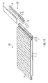
- the IC tag sheet 140 according to this embodiment has a suction sheet 7 formed on a surface of the base sheet 1 of the IC tag sheet 110 according to Embodiment 1, opposite to the surface where the sticks 2 are formed.
- components identical to those of the IC tag sheet 110 in Embodiment 1 will be assigned with the identical numerals and the explanation will be omitted.
- FIG. 10 is a perspective view showing a configuration of a surface of the suction sheet 7 where the suction discs 7a are arranged.
- Each of the suction discs 7a is 5 mm in diameter and 50 ⁇ m in height.
- the suction sheet 7 is formed by printing a flexible suction ink on a sheet made of polyolefin-based synthetic resin, a polyester resin, polyvinyl chloride resin or the like, by using a screen printing method or the like. Therefore, the shape and size of the suction discs can be set arbitrarily.
- the IC tag sheet 140 can be fixed by joining the suction discs to the attachment object. Since the IC tag sheet 140 using the suction sheet 7 does not require either an adhesive or any mechanism for hooking or entangling, the attachment object will not be damaged.
- FIG. 11 is an exploded perspective view showing a configuration of the IC tag sheet 140 formed by bonding the base sheet 1 and the suction sheet 7. In the step of bonding the base sheet 1 and the suction sheet 7 for forming the IC tag sheet 140, the IC tag 6 is placed at a predetermined position on the suction sheet 7.
- the IC tag 6 is placed so that the longitudinal direction corresponds to the longitudinal direction of the sticks 2. Accordingly, damage of the IC tag 6 caused by bending of the IC tag sheet 140 can be prevented.
- This configuration serves also to protect the IC tag 6 from damage in use or damage caused by stains, impact or the like. In addition to that, since a step of sealing the IC tag 6 in the stick 2 or the base 1 is not required, the IC tag sheet 140 can be manufactured at low cost.
- the joint 3a as shown in FIG. 3 can be integrated with the suction sheet 7.
- FIG. 12A is a perspective view showing the IC tag sheet 140 according to this embodiment attached to wires 17, and FIG. 12B is the cross-sectional view.
- the suction discs 7a of the suction sheet 7 are joined to the wires 17 so as to fix the IC tag sheet 140 to the wires 17. Since the suction discs 7a are formed by a screen printing method or the like as mentioned above, small suction discs 7a having a diameter of several millimeters can be formed. Therefore, even when the attachment object includes a plurality of wires 17 with small radii, the suction discs 7a can be joined to the surfaces of the wires 17 so as to fix the IC tag sheet 140.
- the attachment object includes plural wires 17 or the like, even a suction disc 7a not joined to the attachment object provides an effect of securing the wires with their surface asperities.
- IC tag sheet 140 is not limited to winding around an attachment object to be fixed.
- Such an IC tag sheet 140 can be bonded in use to a soft member of polypropylene or the like, or to a solid matter having a cylindrical surface such as a cylinder side. Since the bending direction of the IC tag sheet 140 is restricted by the sticks 2, breakage in the IC tag 6 can be prevented even if the IC tag sheet 140 is bonded to a soft member. In this application, a joint 3 is not required.
- FIG. 13 is an exploded perspective view showing a configuration of an IC tag plate 20 that can be placed on the joint 3.
- the IC tag 6 is placed in a sealing resin 18 of the substantially same material as the base sheet 1.
- the sealing resin 18 is formed to be rectangular.
- a plate 19 made of a material having Young's modulus of the substantially same level as the sticks 2 is disposed.
- Upper ridges 14 are formed on the face opposite to plate 19 in order to fit with the lower ridges 13 of the joint 3.
- the plate 19 can be replaced by the sticks 2.
- the IC tag 6 can be placed or not on the IC tag sheet 140 on which the IC tag plate 20 will be placed.
- a hook-and-loop fastener or a suction surface is formed on the surface of the IC tag plate 20 where the upper ridges 14 are formed, in accordance with the lower joint 11 to be joined.
- the IC tag can be exchanged easily, and thus IC tags can be used properly in light of the properties such as capacity and transmission distance.
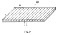
- FIG. 14 is a perspective view showing a configuration of an IC tag sheet 150 as a variation of the IC tag sheet 140 to be wound around an attachment object so as to be fixed in use.
- the IC tag sheet 150 will be fixed to the attachment object via the suction discs of the suction sheet 7 joined to the surface of the base sheet 1.
- the suction disc diameter can be decreased in accordance with the shape of the sticks 2 so as to be joined to the sticks 2.
- the adsorption area is reduced and thus degrades the bonding strength.
- the IC tag sheet 150 is configured by covering the sticks 2 on the base sheet 1 with a covering member 21 made of a resin or the like, containing the sticks 2 in the base sheet 1 so as to provide a flat surface.
- This configuration serves to facilitate winding and detachment, and also allows a repeated attachment. Furthermore, since the suction discs are joined to the surface, the winding length can be adjusted according to the size of the attachment object.
- the IC tag sheets 140 and 150 according to this embodiment can be bent only in a predetermined direction, and thus deformation and cutting of the IC tag 6 caused by bending can be prevented.
- the size and shape of the suction discs 7a of the suction sheet 7 are not limited to those as shown in FIG. 10, but they can be shaped rectangular or polygonal.
- FIG. 15 is a perspective view showing a configuration of an IC tag sheet 160 according to Embodiment 3 of the present invention.
- the IC tag sheet 160 according to this embodiment is configured by binding the sticks 2 to form a roller screen, without using the base sheet 1 of the IC tag sheet 110 according to Embodiment 1.
- components identical to those of the IC tag sheet 110 according to Embodiment 1 will be assigned with the identical numerals and the explanation will be omitted.
- the IC tag sheet 160 is formed of cylindrical sticks 2 arranged in the short direction, and an IC tag 6 is included in at least one of the sticks 2.
- the sticks 2 are tied and bound with fibrous binding members 22.
- the IC tag sheet 160 is formed to be bendable in the short direction, but unbendable in the longitudinal direction of the sticks 2. That is, the IC tag sheet 160 cannot be bent in the longitudinal direction of the antenna module 5 but it can be bent in the short direction, thereby preventing breakage of the IC tag 6, particularly cutting and deformation at the joints between the antenna module 5 and the chip module 4 and also at the antenna module 5.
- the material for the binding members 22 is not limited to fibers to tie the sticks 2, but flexible resins or the like can be used as well so as to adhere the sticks 2 to each other.
- Hook-shaped anchors as joints 3d can be provided also to the IC tag sheet 160. By hooking these anchors on a stick 2 at any suitable position, the length of the IC tag sheet 160 can be adjusted in accordance with the size of the attachment object.
- the joints 3d are not limited to the hook-shape anchors, but for example, a suction member can be used alternatively to be joined to the stick 2.
- FIG. 16 is a perspective view showing a configuration of a joint 3e as a variation of the joint 3d for an IC tag sheet.
- the joint 3e in an IC tag sheet 170 is composed of a pair of sticks 2e positioned respectively at the both edges of the IC tag sheet 170 and a U-shaped joint jig 23.
- the sticks 2e are formed with hollows 2f.
- the joint jig 23 can be inserted into the hollows 2f. By inserting the joint jig 23 into the hollows 2f of the sticks 2e, the IC tag sheet 170 can be wound around the attachment object easily.
- the inner surface to contact with the attachment object is not smooth. This is advantageous in securing plural attachment objects.
- a suction member can be attached to the inner surface of the IC tag sheet 160.
- the IC tag sheet 160 according to this embodiment can be bent only in a predetermined direction, and thus deformation and cutting of the IC tag 6 caused by bending can be prevented.
Landscapes
- Engineering & Computer Science (AREA)
- Physics & Mathematics (AREA)
- General Physics & Mathematics (AREA)
- Theoretical Computer Science (AREA)
- Computer Hardware Design (AREA)
- Microelectronics & Electronic Packaging (AREA)
- Credit Cards Or The Like (AREA)
Abstract
Description
- The present invention relates to an IC tag sheet including an IC tag.
- Recently, barcodes and IC tags have been used from the viewpoint of information management such as product traceability of and calculation of fares/fees. Currently, barcodes have become the mainstream of information management of products. Abarcode, which is printed on a product or the package, can be provided at a low cost. However, the barcode can contain only a small amount of information, and thus it cannot serve for detailed management of the product.
- An IC tag can store much information in comparison with a barcode, and thus an IC tag serves to provide a more detailed management of a product. Moreover, since such an IC tag can be fed with energy from a reader, it does not require a battery. Furthermore, the IC tag is more preferable to the barcode in view of management for maintenance, since the IC tag allows reading of information even if stains or dust are present. In addition, the IC tag can be used repeatedly since information in the IC tag can be added or changed. With the recent tendency toward reduction of the unit price of the IC tag, demand for the IC tag has been increased rapidly.
- FIG. 17 is a plan view schematically showing a configuration of a typical IC tag (see
JP2000-222540 A chip module 201 stores information from an exterior apparatus at the time of writing and outputs the thus stored information at the time of reading. Anantenna module 202 transmits/receives information with an exterior apparatus (reader) through radio transmission. When theantenna module 202 is a dipole antenna, its length is determined (1/2 wavelength in general) depending on the frequency of the electromagnetic wave for transmission/reception with the exterior apparatus. For example, when the frequency is 2.45 GHz, the 1/2 wavelength is 61 mm. Thechip module 201 and theantenna module 202 are formed independently and joined to each other by using a joining technique. - The
antenna module 202 of the IC tag is as long as 61 mm as mentioned above. In a case of using a coil antenna for theantenna module 202, the coil is formed in a region of 18 mm x 32 mm for example, and thus it will require a large area. Such an IC tag will be broken or deformed easily due to bending, particularly at the joint between thechip module 201 and theantenna module 202 and also at theantenna module 202, causing degradation in the communication property. Typically therefore, the IC tag is formed in a plastic card or in a label to be bonded to a solid material. - For linear products such as wires and fishing rods having simple shapes, it will be difficult to decide visually the specifications such as the type and the length. For a wire configured by connecting plural kinds of wires, even for a general-purpose wire, the properties will change depending on the connection of the wires, and the properties will change further when there are any change in the connection of the wires. It is difficult to manage such a wire with an unrewritable tag like a barcode.
- An IC tag is rewritable but susceptible to bending, and thus it is difficult to wind the IC tag around a wire and to manage the wire. When the strength of the IC tag against bending is improved for the use/purpose, the cost will be increased.
- Therefore, with the foregoing in mind, it is an object of the present invention to avoid the above-mentioned problems by providing an IC tag sheet resistant to breakage of the IC tag and degradation in the communication property even when the IC tag sheet is bent in a predetermined direction.
- For achieving the object, a first IC tag of the present invention includes a base sheet, a plurality of stick members arranged in parallel on the base sheet, and an IC tag placed in at least one of the stick members. The longitudinal direction of the IC tag corresponds to the longitudinal direction of the stick members.
- A second IC tag sheet of the present invention includes a base sheet, a plurality of stick members arranged in parallel on the surface of the base sheet, and an IC tag placed on or in the base sheet. The longitudinal direction of the IC tag corresponds to the longitudinal direction of the stick members.
- A third IC tag sheet of the present invention includes a plurality of stick members arranged in the short direction, binding members for binding the stick members, and an IC tag placed in at least one of the stick members. The longitudinal direction of the IC tag corresponds to the longitudinal direction of the stick members.
- FIG. 1 is a perspective view showing a configuration of an IC tag sheet according to
Embodiment 1 of the present invention. - FIG. 2Ais a perspective view showing a configuration of a stick of the IC tag sheet.
- FIG. 2B is a perspective view showing another configuration of a stick of the IC tag sheet.
- FIG. 3 is a cross-sectional view showing a configuration of a joint of the IC tag sheet.
- FIG. 4 is a cross-sectional view showing another configuration of a joint of the IC tag sheet.
- FIG. 5 is a cross-sectional view showing another configuration of a joint of the IC tag sheet.
- FIG. 6 is a perspective view showing an IC tag sheet wound around wires, according to Embodiment 1 of the present invention.
- FIG. 7 is an exploded perspective view showing another configuration of the IC tag sheet according to
Embodiment 1 of the present invention. - FIG. 8 is an exploded perspective view showing another configuration of the IC tag sheet.
- FIG. 9 is a perspective view showing a configuration of an IC tag sheet according to
Embodiment 2 of the present invention. - FIG. 10 is a perspective view showing a configuration of a suction sheet of the IC tag sheet.
- FIG. 11 is an exploded perspective view showing a configuration of the IC tag sheet.
- FIG. 12A is a perspective view showing the IC tag sheet wound around a bundle of wires.
- FIG. 12B is a cross-sectional view of the IC tag sheet and the wires shown in FIG. 12A.
- FIG. 13 is an exploded perspective view showing an IC tag plate to be attached to a joint of the IC tag sheet.
- FIG. 14 is a perspective view showing another configuration of the IC tag sheet.
- FIG. 15 is a perspective view showing a configuration of an IC tag sheet according to
Embodiment 3 of the present invention. - FIG. 16 is a perspective view showing another configuration of a joint of an IC tag sheet according to
Embodiment 3 of the present invention. - FIG. 17 is a plan view showing a configuration of a typical IC tag sheet.
- In an IC tag sheet of the present invention, the stick members can have Young's modulus higher than that of the base sheet. Accordingly, the IC tag sheet will be unbendable in the longitudinal direction but bendable in the short direction of the stick members.
- Furthermore, the IC tag sheet can have joints at the both edges to be joined with each other. Accordingly, the IC tag sheet can be wound around an attachment object.
- Alternatively, the IC tag sheet can have a suction member on a surface of the base sheet opposite to the surface where the stick members are arranged. Accordingly, the IC tag sheet can be joined to the attachment object and fixed.
- Alternatively, the IC tag can be placed between the base sheet and the suction member. Accordingly, the IC tag sheet will not be bent in the longitudinal direction of the IC tag, and thus breakage and degradation in property of the IC tag can be prevented.
- The suction member can be formed as a suction sheet. Accordingly, the suction member can be formed easily on the base sheet.
- Hereinafter, embodiments of the IC tag sheet of the present invention will be described below with reference to attached figures.
- FIG. 1 is a perspective view showing an exemplary configuration of an
IC tag sheet 110 according toEmbodiment 1 of the present invention. Abase sheet 1 is made of a flexible resin or the like. On thebase sheet 1, a plurality of sticks 2 (stick members) are arranged in parallel. An IC tag (not shown) is sealed in at least one of the thus arranged sticks 2.Joints 3 are formed at the both edges of thebase sheet 1. Thejoints 3 are joined with each other so that the IC tag sheet can be wound around an attachment object (not shown) and fixed. - Hereinafter, respective components will be described more in detail. First, sticks 2 will be described below. It is preferable that the
sticks 2 are made of a material having Young's modulus higher than that of thebase sheet 1. Since thesticks 2 are arranged in parallel on thebase sheet 1, theIC tag sheet 110 cannot be bent in the longitudinal direction (unbendable direction) but it can be bent in the short direction (bendable direction) of thesticks 2. It is also preferable that the number of thesticks 2 to be arranged on theIC tag sheet 110 is determined to prevent deformation of the IC tag against the maximum force applied in the unbendable direction. - The cross section of the
stick 2 is not limited to the semicircle as shown in FIG. 1, but it can be a circle, a rectangle, an ellipse, a polygon or the like in accordance with the use. It is also possible to arrange thesticks 2 with suitable spacing between them on thebase sheet 1. Accordingly,adjacent sticks 2 will not snag each other when theIC tag sheet 110 is bent due to a force applied in the bendable direction. It is also possible to coat thesticks 2 with a resin so as to provide a flat surface. - Next description is about the positional relationship between the IC tag and the
sticks 2. FIG. 2Ais a perspective view showing a configuration of astick 2 including the IC tag, which is arranged on theIC tag sheet 110 according to this embodiment. TheIC tag 6 has achip module 4 and anantenna module 5. Theantenna module 5 is a dipole antenna. TheIC tag 6 is sealed in thestick 2 and placed so that the longitudinal direction of theantenna module 5 corresponds to the longitudinal direction (unbendable direction) of thestick 2. Accordingly, theIC tag sheet 110 cannot be bent in the longitudinal direction of theantenna module 5 but can be bent in the short direction (bendable direction). Therefore, breakage, or more specifically cutting (disconnection) or deformation at the joint between theantenna module 5 and thechip module 4 and also at theantenna module 5 can be prevented, since theIC tag 6 itself will not be bent. Alternatively, anIC tag 6 including a coil antenna or the like can be used as long as theIC tag 6 can be inserted in thestick 2. - The
IC tag 6 can be included in thestick 2 in an alternative manner. FIG. 2B is a perspective view showing a variation of thestick 2 that includes theIC tag 6 and that is placed on theIC tag sheet 110 according to this embodiment. In astick 2b, a hollow 2d for accepting theIC tag 6 is formed and acap 2c is provided at the edge of thestick 2 so that theIC tag 6 can be taken out. Preferably the hollow 2d is shaped in accordance with the shape of theIC tag 6 so as to prevent breakage of theIC tag 6. Accordingly, theIC tag 6 can be reused. - As mentioned above, according to the configuration of sealing the
IC tag 6 in thestick 2, theIC tag 6 can be prevented from damage caused by not only warping of an attachment object and damage in use, but also damage caused by stains and impacts. - The following description is about the
joints 3. At one edge of theIC tag sheet 110 in FIG. 1, the upper face of thebase sheet 1 is trimmed to form a lower joint 11. At the other edge, the lower face of thebase sheet 1 is trimmed to form an upper joint 12. At the lower joint 11, twolower ridges 13 are formed in the longitudinal direction of thesticks 2. Furthermore, in the longitudinal direction of thesticks 2, twoupper ridges 14 are formed at the upper joint 12 so as to fit with thelower ridges 13, thereby a zipper of a dual structure is provided with theselower ridges 13 and theupper ridges 14. - Accordingly, the
IC tag sheet 110 can be wound around the attachment object. - It is also possible to connect plural
IC tag sheets 110 at therespective joints 3 and wind them around a large attachment object. - It is also possible that respectively more than two
lower ridges 13 andupper ridges 14 are provided. Accordingly, it is possible to improve the joining strength or adjust the winding length in accordance with the size of the attachment object. - It is also possible to replace the zipper composed of the lower joint 11 and the upper joint 12 by a pair of hook- and-loop fasteners. Accordingly, the winding length can be adjusted in accordance with the size of the attachment object.
- FIG. 3 is a cross-sectional view showing a configuration of a joint 3a as a variation of the joint 3 in the
IC tag sheet 110 according to this embodiment. The joint 3a is composed of aspherical protrusion 15a formed on one edge and aspherical recess 16a formed on the other edge of thebase sheet 1. TheIC tag sheet 110 is wound around the attachment object by fitting theprotrusion 15a and therecess 16a. - FIG. 4 is a cross-sectional view showing a configuration of a joint 3b as a variation of the joint 3 in the
IC tag sheet 110 according to this embodiment. The joint 3b is composed of aspherical protrusion 15b formed on the lower joint 11 and aspherical recess 16b formed on the upper joint 12. TheIC tag sheet 110 is wound around the attachment object by fitting theprotrusion 15b and therecess 16b. - FIG. 5 is a cross-sectional view showing a configuration of a joint 3c composed of
plural protrusions 15b and recesses 16b of the joint 3b as shown in FIG. 4. TheIC tag sheet 110 is attached to the attachment object by fitting theprotrusions 15b and therecesses 16b. The length of thisIC tag sheet 110 in the attachment can be adjusted by shifting the fitting position of theprotrusions 15b and therecesses 16b. - FIG. 6 is a perspective view showing the
IC tag sheet 110 according to this embodiment, which is attached towires 17 as an attachment object. TheIC tag sheet 110 is bent in the bendable direction so as to tie thewires 17. Properties of thewires 17 such as resistance, materials, length and diameter are recorded on theIC tag 6 of theIC tag sheet 110, and the recorded information can be read out by a reader. Accordingly, the properties of thewires 17 can be checked easily. - As mentioned above, the
IC tag sheet 110 according to this embodiment can be bent only in a predetermined direction (bendable direction), thereby preventing deformation and cutting of theIC tag 6 caused by bending. - As shown in FIG. 7, an
IC tag 6 for anIC tag sheet 120 can be formed not in astick 2 but on thebase sheet 1. Though some of thesticks 2 are separated from thebase sheet 1 in FIG. 7 in order to show theIC tag 6, actually thebase sheet 1 and thesticks 2 are bonded to each other. In this case, since the longitudinal direction of thesticks 2 and the longitudinal direction of theIC tag 6 correspond to each other in the arrangement, theIC tag 6 will not be bent in the longitudinal direction. Therefore, breakage, cutting and degradation in the properties of theIC tag 6 can be prevented. - As shown in an
IC tag 130 as shown in FIG. 8, anIC tag 6 can be formed not in thestick 2 but in thebase sheet 1. In FIG. 8, somesticks 2 are shown in a state separated from thebase sheet 1 just like in FIG. 7 in order to show theIC tag 6. Actually, thebase sheet 1 and thesticks 2 are bonded to each other. In this case, since the longitudinal direction of thesticks 2 and the longitudinal direction of theIC tag 6 correspond to each other, theIC tag 6 will not be bent in the longitudinal direction. Therefore, breakage, cutting and degradation in the properties of theIC tag 6 can be prevented. - FIG. 9 is a perspective view showing a configuration of an
IC tag sheet 140 according toEmbodiment 2 of the present invention. TheIC tag sheet 140 according to this embodiment has asuction sheet 7 formed on a surface of thebase sheet 1 of theIC tag sheet 110 according toEmbodiment 1, opposite to the surface where thesticks 2 are formed. In theIC tag sheet 140 in this embodiment, components identical to those of theIC tag sheet 110 inEmbodiment 1 will be assigned with the identical numerals and the explanation will be omitted. - One surface of the
suction sheet 7 is adhered to thebase sheet 1, and suction discs (suction member) are placed on the opposite surface. FIG. 10 is a perspective view showing a configuration of a surface of thesuction sheet 7 where thesuction discs 7a are arranged. Each of thesuction discs 7a is 5 mm in diameter and 50 µm in height. Thesuction sheet 7 is formed by printing a flexible suction ink on a sheet made of polyolefin-based synthetic resin, a polyester resin, polyvinyl chloride resin or the like, by using a screen printing method or the like. Therefore, the shape and size of the suction discs can be set arbitrarily. TheIC tag sheet 140 can be fixed by joining the suction discs to the attachment object. Since theIC tag sheet 140 using thesuction sheet 7 does not require either an adhesive or any mechanism for hooking or entangling, the attachment object will not be damaged. - The
IC tag 6 can be formed in thestick 2. Alternatively, theIC tag 6 can be placed between thebase sheet 1 and thesuction sheet 7. FIG. 11 is an exploded perspective view showing a configuration of theIC tag sheet 140 formed by bonding thebase sheet 1 and thesuction sheet 7. In the step of bonding thebase sheet 1 and thesuction sheet 7 for forming theIC tag sheet 140, theIC tag 6 is placed at a predetermined position on thesuction sheet 7. - The
IC tag 6 is placed so that the longitudinal direction corresponds to the longitudinal direction of thesticks 2. Accordingly, damage of theIC tag 6 caused by bending of theIC tag sheet 140 can be prevented. This configuration serves also to protect theIC tag 6 from damage in use or damage caused by stains, impact or the like. In addition to that, since a step of sealing theIC tag 6 in thestick 2 or thebase 1 is not required, theIC tag sheet 140 can be manufactured at low cost. - As shown in FIG. 11, it is also possible to form the lower joint 11 of the joint 3 in FIG. 1, 4 or 5 on the
suction sheet 7 opposite to the surface where the suction discs are formed, while the upper joint 12 is formed on the back face of thebase sheet 1. Alternatively, the joint 3a as shown in FIG. 3 can be integrated with thesuction sheet 7. - FIG. 12A is a perspective view showing the
IC tag sheet 140 according to this embodiment attached towires 17, and FIG. 12B is the cross-sectional view. When theIC tag sheet 140 is attached to thewires 17, thesuction discs 7a of thesuction sheet 7 are joined to thewires 17 so as to fix theIC tag sheet 140 to thewires 17. Since thesuction discs 7a are formed by a screen printing method or the like as mentioned above,small suction discs 7a having a diameter of several millimeters can be formed. Therefore, even when the attachment object includes a plurality ofwires 17 with small radii, thesuction discs 7a can be joined to the surfaces of thewires 17 so as to fix theIC tag sheet 140. - When the attachment object includes
plural wires 17 or the like, even asuction disc 7a not joined to the attachment object provides an effect of securing the wires with their surface asperities. - Application of the
IC tag sheet 140 according to this embodiment is not limited to winding around an attachment object to be fixed. Such anIC tag sheet 140 can be bonded in use to a soft member of polypropylene or the like, or to a solid matter having a cylindrical surface such as a cylinder side. Since the bending direction of theIC tag sheet 140 is restricted by thesticks 2, breakage in theIC tag 6 can be prevented even if theIC tag sheet 140 is bonded to a soft member. In this application, a joint 3 is not required. - Alternatively in this embodiment, an IC tag plate including the
IC tag 6 can be attached to thelower ridges 13 forming a zipper. FIG. 13 is an exploded perspective view showing a configuration of anIC tag plate 20 that can be placed on thejoint 3. TheIC tag 6 is placed in a sealingresin 18 of the substantially same material as thebase sheet 1. The sealingresin 18 is formed to be rectangular. On one surface of the sealingresin 18, aplate 19 made of a material having Young's modulus of the substantially same level as thesticks 2 is disposed.Upper ridges 14 are formed on the face opposite to plate 19 in order to fit with thelower ridges 13 of thejoint 3. - The
plate 19 can be replaced by thesticks 2. TheIC tag 6 can be placed or not on theIC tag sheet 140 on which theIC tag plate 20 will be placed. - It is also possible that a hook-and-loop fastener or a suction surface is formed on the surface of the
IC tag plate 20 where theupper ridges 14 are formed, in accordance with the lower joint 11 to be joined. In a case where such anIC tag plate 20 is applied, the IC tag can be exchanged easily, and thus IC tags can be used properly in light of the properties such as capacity and transmission distance. - FIG. 14 is a perspective view showing a configuration of an
IC tag sheet 150 as a variation of theIC tag sheet 140 to be wound around an attachment object so as to be fixed in use. TheIC tag sheet 150 will be fixed to the attachment object via the suction discs of thesuction sheet 7 joined to the surface of thebase sheet 1. In this case, the suction disc diameter can be decreased in accordance with the shape of thesticks 2 so as to be joined to thesticks 2. However, the adsorption area is reduced and thus degrades the bonding strength. In order to increase the adsorption area, theIC tag sheet 150 is configured by covering thesticks 2 on thebase sheet 1 with a coveringmember 21 made of a resin or the like, containing thesticks 2 in thebase sheet 1 so as to provide a flat surface. This configuration serves to facilitate winding and detachment, and also allows a repeated attachment. Furthermore, since the suction discs are joined to the surface, the winding length can be adjusted according to the size of the attachment object. - As mentioned above, the
IC tag sheets IC tag 6 caused by bending can be prevented. - The size and shape of the
suction discs 7a of thesuction sheet 7 are not limited to those as shown in FIG. 10, but they can be shaped rectangular or polygonal. - FIG. 15 is a perspective view showing a configuration of an
IC tag sheet 160 according toEmbodiment 3 of the present invention. TheIC tag sheet 160 according to this embodiment is configured by binding thesticks 2 to form a roller screen, without using thebase sheet 1 of theIC tag sheet 110 according toEmbodiment 1. In theIC tag sheet 160 according to this embodiment, components identical to those of theIC tag sheet 110 according toEmbodiment 1 will be assigned with the identical numerals and the explanation will be omitted. - The
IC tag sheet 160 is formed ofcylindrical sticks 2 arranged in the short direction, and anIC tag 6 is included in at least one of thesticks 2. Thesticks 2 are tied and bound with fibrous bindingmembers 22. As a result, theIC tag sheet 160 is formed to be bendable in the short direction, but unbendable in the longitudinal direction of thesticks 2. That is, theIC tag sheet 160 cannot be bent in the longitudinal direction of theantenna module 5 but it can be bent in the short direction, thereby preventing breakage of theIC tag 6, particularly cutting and deformation at the joints between theantenna module 5 and thechip module 4 and also at theantenna module 5. - The material for the binding
members 22 is not limited to fibers to tie thesticks 2, but flexible resins or the like can be used as well so as to adhere thesticks 2 to each other. - Hook-shaped anchors as
joints 3d can be provided also to theIC tag sheet 160. By hooking these anchors on astick 2 at any suitable position, the length of theIC tag sheet 160 can be adjusted in accordance with the size of the attachment object. Thejoints 3d are not limited to the hook-shape anchors, but for example, a suction member can be used alternatively to be joined to thestick 2. - FIG. 16 is a perspective view showing a configuration of a joint 3e as a variation of the joint 3d for an IC tag sheet. The joint 3e in an
IC tag sheet 170 is composed of a pair of sticks 2e positioned respectively at the both edges of theIC tag sheet 170 and a U-shapedjoint jig 23. The sticks 2e are formed withhollows 2f. Thejoint jig 23 can be inserted into thehollows 2f. By inserting thejoint jig 23 into thehollows 2f of the sticks 2e, theIC tag sheet 170 can be wound around the attachment object easily. - Since the
IC tag sheet 160 has no base sheet or cover member, the inner surface to contact with the attachment object is not smooth. This is advantageous in securing plural attachment objects. - Alternatively, a suction member can be attached to the inner surface of the
IC tag sheet 160. - As mentioned above, the
IC tag sheet 160 according to this embodiment can be bent only in a predetermined direction, and thus deformation and cutting of theIC tag 6 caused by bending can be prevented. - The present invention will not be limited to Embodiments 1-3, especially there is no particular limitation for the number of the
sticks 2 as shown in the drawings.
Claims (14)
- An IC tag sheet comprising:a base sheet,a plurality of stick members arranged in parallel on the base sheet, andan IC tag placed in at least one of the stick members; andthe longitudinal direction of the IC tag corresponds to the longitudinal direction of the stick members.
- The IC tag sheet according to claim 1, wherein the stick members have Young's modulus higher than Young's modulus of the base sheet.
- The IC tag sheet according to claim 1, comprising joints at the edges to be joined with each other.
- The IC tag sheet according to claim 1, comprising a suction member on the surface of the base sheet opposite to the surface where the stick members are arranged.
- The IC tag sheet according to claim 4, wherein the IC tag is placed between the base sheet and the suction member.
- The IC tag sheet according to claim 4, wherein the suction member is a suction sheet.
- An IC tag sheet comprising:a base sheet,a plurality of stick members arranged in parallel on the base sheet, andan IC tag placed on or in the base sheet; andthe longitudinal direction of the IC tag corresponds to the longitudinal direction of the stick members.
- The IC tag sheet according to claim 7, wherein the stick members have Young's modulus higher than Young's modulus of the base sheet.
- The IC tag sheet according to claim 7, comprising joints at the edges to be joined with each other.
- The IC tag sheet according to claim 7, comprising a suction member on the surface of the base sheet opposite to the surface where the stick members are arranged.
- The IC tag sheet according to claim 10, wherein the IC tag is placed between the base sheet and the suction member.
- The IC tag sheet according to claim 10, wherein the suction member is a suction sheet.
- An IC tag sheet comprising:a plurality of stick members arranged in the short direction,a binding member for binding the stick members, andan IC tag placed in at least one of the stick members; andthe longitudinal direction of the IC tag corresponds to the longitudinal direction of the stick members.
- The IC tag sheet according to claim 13, comprising joints at the edges to be joined with each other.
Applications Claiming Priority (1)
| Application Number | Priority Date | Filing Date | Title |
|---|---|---|---|
| JP2006055357A JP2007233756A (en) | 2006-03-01 | 2006-03-01 | Ic tag sheet |
Publications (2)
| Publication Number | Publication Date |
|---|---|
| EP1830311A2 true EP1830311A2 (en) | 2007-09-05 |
| EP1830311A3 EP1830311A3 (en) | 2008-10-22 |
Family
ID=38137459
Family Applications (1)
| Application Number | Title | Priority Date | Filing Date |
|---|---|---|---|
| EP07250869A Withdrawn EP1830311A3 (en) | 2006-03-01 | 2007-03-01 | IC tag sheet |
Country Status (4)
| Country | Link |
|---|---|
| US (1) | US20070205901A1 (en) |
| EP (1) | EP1830311A3 (en) |
| JP (1) | JP2007233756A (en) |
| CN (1) | CN101030265A (en) |
Cited By (1)
| Publication number | Priority date | Publication date | Assignee | Title |
|---|---|---|---|---|
| WO2023274463A1 (en) * | 2021-06-30 | 2023-01-05 | Pepperl+Fuchs Se | Device for presenting a code |
Families Citing this family (2)
| Publication number | Priority date | Publication date | Assignee | Title |
|---|---|---|---|---|
| US7847697B2 (en) * | 2008-02-14 | 2010-12-07 | 3M Innovative Properties Company | Radio frequency identification (RFID) tag including a three-dimensional loop antenna |
| JP7082874B2 (en) * | 2017-12-26 | 2022-06-09 | ヤマシンフィルタ株式会社 | Filter device |
Family Cites Families (9)
| Publication number | Priority date | Publication date | Assignee | Title |
|---|---|---|---|---|
| US2080058A (en) * | 1935-06-10 | 1937-05-11 | Wiley W Osborne | Hose supporting accessory |
| US5251189A (en) * | 1992-10-16 | 1993-10-05 | Timex Corporation | Wristwatch radiotelephone |
| US5581445A (en) * | 1994-02-14 | 1996-12-03 | Us3, Inc. | Plastic integrated circuit card with reinforcement structure for protecting integrated circuit module |
| AU6270599A (en) * | 1999-07-01 | 2001-01-22 | Intermec Ip Corp. | Integrated circuit attachment process and apparatus |
| GB0004688D0 (en) * | 2000-02-28 | 2000-04-19 | Radley Smith Philip J | Bracelet |
| US7017799B2 (en) * | 2001-12-04 | 2006-03-28 | The Gates Corporation | Spindle sleeve with transponder |
| US20050108912A1 (en) * | 2003-11-25 | 2005-05-26 | Alexander Bekker | Identification tag and related identification tag system |
| DE102004003461C5 (en) * | 2004-01-22 | 2009-11-19 | ASTRA Gesellschaft für Asset Management mbH & Co. KG | Textile material with an HF transponder |
| US20060166720A1 (en) * | 2004-10-19 | 2006-07-27 | Herman Dixon | Universal wrist worn holder for cellular phones |
-
2006
- 2006-03-01 JP JP2006055357A patent/JP2007233756A/en not_active Withdrawn
-
2007
- 2007-02-28 US US11/711,974 patent/US20070205901A1/en not_active Abandoned
- 2007-03-01 EP EP07250869A patent/EP1830311A3/en not_active Withdrawn
- 2007-03-01 CN CNA2007100846778A patent/CN101030265A/en active Pending
Cited By (4)
| Publication number | Priority date | Publication date | Assignee | Title |
|---|---|---|---|---|
| WO2023274463A1 (en) * | 2021-06-30 | 2023-01-05 | Pepperl+Fuchs Se | Device for presenting a code |
| EP4163823A1 (en) * | 2021-06-30 | 2023-04-12 | Pepperl+Fuchs SE | Device for presenting a code |
| CN116210001A (en) * | 2021-06-30 | 2023-06-02 | 佩佩尔+富克斯欧洲股份公司 | Apparatus for presenting codes |
| US12236299B2 (en) | 2021-06-30 | 2025-02-25 | Pepperl+Fuchs Se | Device for presenting a code |
Also Published As
| Publication number | Publication date |
|---|---|
| JP2007233756A (en) | 2007-09-13 |
| CN101030265A (en) | 2007-09-05 |
| US20070205901A1 (en) | 2007-09-06 |
| EP1830311A3 (en) | 2008-10-22 |
Similar Documents
| Publication | Publication Date | Title |
|---|---|---|
| US7479888B2 (en) | RFID tag label | |
| JP6028435B2 (en) | RFID tag | |
| EP0595549A2 (en) | Radio frequency baggage tags | |
| JP2007007888A (en) | Non-contact IC chip mounting body mounted cardboard and manufacturing method thereof | |
| JP2006107296A (en) | Non-contact IC tag and antenna for non-contact IC tag | |
| EP1962233B1 (en) | Radio frequency tag and method for manufacturing radio frequency tag | |
| US20070205901A1 (en) | IC tag sheet | |
| EP2065841B1 (en) | Electronic apparatus and method of manufacturing the same | |
| CN100559394C (en) | radio frequency identification tag | |
| CN101013476A (en) | Method of reeling a series of RFID tags and RFID tag roll | |
| US9152902B2 (en) | Identification document with a contactless RFID chip | |
| JP2013030069A (en) | Ic tag and manufacturing method thereof | |
| US20130015246A1 (en) | Security tag, assembly having a security tag, and method for operation of a security tag | |
| KR100384573B1 (en) | Spool sleeve with a transponder, especially for glass fiber spinning bobbins | |
| KR101167467B1 (en) | Rfid label tag | |
| KR20120111343A (en) | Packaging material for use in distribution management with rfid tag | |
| JP4923196B2 (en) | Plastic pallet | |
| JP5354744B2 (en) | IC module | |
| JP7540365B2 (en) | Continuous form paper | |
| JP4844058B2 (en) | Print media | |
| JP2007065088A (en) | RFID tag and RFID label | |
| JP4281516B2 (en) | RFID tag circuit element and RFID tag cartridge | |
| JP2007102047A (en) | Product management tag | |
| JP2009301099A (en) | Rfid media | |
| JP2005157780A (en) | Tag-type information recording medium |
Legal Events
| Date | Code | Title | Description |
|---|---|---|---|
| PUAI | Public reference made under article 153(3) epc to a published international application that has entered the european phase |
Free format text: ORIGINAL CODE: 0009012 |
|
| AK | Designated contracting states |
Kind code of ref document: A2 Designated state(s): AT BE BG CH CY CZ DE DK EE ES FI FR GB GR HU IE IS IT LI LT LU LV MC MT NL PL PT RO SE SI SK TR |
|
| AX | Request for extension of the european patent |
Extension state: AL BA HR MK YU |
|
| PUAL | Search report despatched |
Free format text: ORIGINAL CODE: 0009013 |
|
| AK | Designated contracting states |
Kind code of ref document: A3 Designated state(s): AT BE BG CH CY CZ DE DK EE ES FI FR GB GR HU IE IS IT LI LT LU LV MC MT NL PL PT RO SE SI SK TR |
|
| AX | Request for extension of the european patent |
Extension state: AL BA HR MK RS |
|
| RIC1 | Information provided on ipc code assigned before grant |
Ipc: G06K 19/04 20060101ALI20080915BHEP Ipc: G06K 19/077 20060101AFI20070626BHEP |
|
| AKX | Designation fees paid | ||
| REG | Reference to a national code |
Ref country code: DE Ref legal event code: 8566 |
|
| STAA | Information on the status of an ep patent application or granted ep patent |
Free format text: STATUS: THE APPLICATION IS DEEMED TO BE WITHDRAWN |
|
| 18D | Application deemed to be withdrawn |
Effective date: 20090423 |