EP1830138A1 - Air conditioner - Google Patents
Air conditioner Download PDFInfo
- Publication number
- EP1830138A1 EP1830138A1 EP05809493A EP05809493A EP1830138A1 EP 1830138 A1 EP1830138 A1 EP 1830138A1 EP 05809493 A EP05809493 A EP 05809493A EP 05809493 A EP05809493 A EP 05809493A EP 1830138 A1 EP1830138 A1 EP 1830138A1
- Authority
- EP
- European Patent Office
- Prior art keywords
- indoor
- power
- unit
- outdoor unit
- outdoor
- Prior art date
- Legal status (The legal status is an assumption and is not a legal conclusion. Google has not performed a legal analysis and makes no representation as to the accuracy of the status listed.)
- Granted
Links
Images


Classifications
-
- F—MECHANICAL ENGINEERING; LIGHTING; HEATING; WEAPONS; BLASTING
- F24—HEATING; RANGES; VENTILATING
- F24F—AIR-CONDITIONING; AIR-HUMIDIFICATION; VENTILATION; USE OF AIR CURRENTS FOR SCREENING
- F24F11/00—Control or safety arrangements
- F24F11/30—Control or safety arrangements for purposes related to the operation of the system, e.g. for safety or monitoring
- F24F11/46—Improving electric energy efficiency or saving
-
- F—MECHANICAL ENGINEERING; LIGHTING; HEATING; WEAPONS; BLASTING
- F24—HEATING; RANGES; VENTILATING
- F24F—AIR-CONDITIONING; AIR-HUMIDIFICATION; VENTILATION; USE OF AIR CURRENTS FOR SCREENING
- F24F11/00—Control or safety arrangements
- F24F11/30—Control or safety arrangements for purposes related to the operation of the system, e.g. for safety or monitoring
-
- F—MECHANICAL ENGINEERING; LIGHTING; HEATING; WEAPONS; BLASTING
- F24—HEATING; RANGES; VENTILATING
- F24F—AIR-CONDITIONING; AIR-HUMIDIFICATION; VENTILATION; USE OF AIR CURRENTS FOR SCREENING
- F24F11/00—Control or safety arrangements
- F24F11/30—Control or safety arrangements for purposes related to the operation of the system, e.g. for safety or monitoring
- F24F11/32—Responding to malfunctions or emergencies
-
- F—MECHANICAL ENGINEERING; LIGHTING; HEATING; WEAPONS; BLASTING
- F24—HEATING; RANGES; VENTILATING
- F24F—AIR-CONDITIONING; AIR-HUMIDIFICATION; VENTILATION; USE OF AIR CURRENTS FOR SCREENING
- F24F11/00—Control or safety arrangements
- F24F11/30—Control or safety arrangements for purposes related to the operation of the system, e.g. for safety or monitoring
- F24F11/49—Control or safety arrangements for purposes related to the operation of the system, e.g. for safety or monitoring ensuring correct operation, e.g. by trial operation or configuration checks
-
- F—MECHANICAL ENGINEERING; LIGHTING; HEATING; WEAPONS; BLASTING
- F24—HEATING; RANGES; VENTILATING
- F24F—AIR-CONDITIONING; AIR-HUMIDIFICATION; VENTILATION; USE OF AIR CURRENTS FOR SCREENING
- F24F11/00—Control or safety arrangements
- F24F11/50—Control or safety arrangements characterised by user interfaces or communication
- F24F11/54—Control or safety arrangements characterised by user interfaces or communication using one central controller connected to several sub-controllers
-
- F—MECHANICAL ENGINEERING; LIGHTING; HEATING; WEAPONS; BLASTING
- F24—HEATING; RANGES; VENTILATING
- F24F—AIR-CONDITIONING; AIR-HUMIDIFICATION; VENTILATION; USE OF AIR CURRENTS FOR SCREENING
- F24F11/00—Control or safety arrangements
- F24F11/88—Electrical aspects, e.g. circuits
-
- F—MECHANICAL ENGINEERING; LIGHTING; HEATING; WEAPONS; BLASTING
- F24—HEATING; RANGES; VENTILATING
- F24F—AIR-CONDITIONING; AIR-HUMIDIFICATION; VENTILATION; USE OF AIR CURRENTS FOR SCREENING
- F24F11/00—Control or safety arrangements
- F24F11/50—Control or safety arrangements characterised by user interfaces or communication
- F24F11/52—Indication arrangements, e.g. displays
-
- F—MECHANICAL ENGINEERING; LIGHTING; HEATING; WEAPONS; BLASTING
- F24—HEATING; RANGES; VENTILATING
- F24F—AIR-CONDITIONING; AIR-HUMIDIFICATION; VENTILATION; USE OF AIR CURRENTS FOR SCREENING
- F24F2221/00—Details or features not otherwise provided for
- F24F2221/32—Details or features not otherwise provided for preventing human errors during the installation, use or maintenance, e.g. goofy proof
Definitions
- the present invention relates to an air conditioner having an indoor unit and an outdoor unit connected via connection wiring.
- an air conditioner which is externally supplied with a power by an outdoor unit and able to reduce the power consumption in a standby state of an indoor unit and the outdoor unit by limiting the supply of a main power to each part via a power line in the standby state (refer to, for example, JP 2000-111123 A ).
- the air conditioner includes the indoor unit, the outdoor unit and a signal line for transmitting and receiving a transmission signal between the indoor unit and the outdoor unit.
- the present applicant has proposed an air conditioner and a control method capable of transmitting the transmission signal at high speed and reducing the power consumption in the standby state of the indoor unit and the outdoor unit. It is noted that the air conditioner and the control method are intended for easy understanding of the present invention and neither a known art nor a prior art.
- a relay is provided between one of power lines that connect the indoor unit with the outdoor unit and the signal line, and an operating power supply relay of the outdoor unit is turned on by transmitting a power for startup to the outdoor unit using the signal line by turning on the relay for a prescribed time when the operation starts from the standby state in which the power of the outdoor unit is cut off.
- connection wires are miswired by mistake in connecting the indoor unit with the outdoor unit by connection wiring lines in the air conditioner, a closed circuit including a power source is formed between a part on the indoor unit side and a part on the outdoor unit side, and this disadvantageously leads to the damage of components.
- an air conditioner according to the first inventive aspect comprises:
- connection wiring lines are connected partially exchanged by connecting the terminal to which the signal line of the indoor unit should be connected with the terminal to which the other of the power lines of the outdoor unit should be connected and connecting the terminal to which the signal line of the outdoor unit should be connected with the terminal to which the other of the power lines of the indoor unit should be connected
- a closed circuit is formed of part of the indoor unit, part of the outdoor unit and the power source via the indoor side switch means when the indoor side switch means is directly brought into the closed state at the startup time when the operation starts from the standby state in which the power supply of the outdoor unit is stopped, and an overcurrent flows through the circuit, disadvantageously damaging the components.
- the indoor control means of the indoor unit determines that the connection wiring lines which connect the indoor unit with the outdoor unit are miswired on the basis of the reception output of the indoor side transmitting and receiving means when the operation starts from the standby state in the miswired state as described above. That is, in the case of the miswiring as described above, it becomes possible to determine that the connection wiring lines are miswired before the indoor side switch means is brought into the closed state by applying the power voltage to the signal line to turn on the reception output of the indoor side transmitting and receiving means. Therefore, even if the operation starts in the state in which the connection wiring lines that connect the indoor unit with the outdoor unit are miswired, the damage of components can be prevented with a simple construction employing the indoor side transmitting and receiving means.
- the indoor control means of the indoor unit determines that the connection wiring lines which connect the indoor unit with the outdoor unit are miswired when the reception output of the indoor side transmitting and receiving means is turned on at the time of starting the operation from the standby state in which the supply of power of the outdoor unit is stopped.
- connection wiring lines are miswired before the indoor side switch means is brought into the closed state by applying the power voltage to the signal line to turn on the reception output of the indoor side transmitting and receiving means in the miswired state as described above.
- the indoor unit comprises an informing means for informing a user of miswiring
- the indoor control means informs the user of miswiring by the informing means upon determining that the connection wiring lines which connect the indoor unit with the outdoor unit are miswired.
- the informing means informs the user of the miswiring upon determining that the connection wiring lines are miswired. Therefore, the operator is able to perceive the cause of the trouble at the time of installation and to swiftly cope with the trouble.
- an air conditioner comprises: an indoor unit and an outdoor unit which are connected via connection wiring; the connection wiring comprising two power lines for supplying a power from an external power source via one of the indoor unit and the outdoor unit to the other of the indoor unit and the outdoor unit, and one signal line for carrying out communication between the indoor unit and the outdoor unit; the indoor unit comprising an indoor side switch means which is connected between one of the power lines and the signal line and brought into a closed state at a startup time when operation starts from a standby state in which the supply of power of the outdoor unit is stopped, and the outdoor unit comprising a startup power supply switch means which is brought into a closed state so that a power for startup is supplied from the indoor unit side via the signal line when the indoor side switch means of the indoor unit is brought into the closed state, an operating power supply switch means which is brought into a closed state so that the power for operation is supplied to a load via the power line in operation while is brought into an open state in the standby state, and an outdoor control means which
- a closed circuit is formed of part of the indoor unit, part of the outdoor unit (including the operating power supply switch means and the startup power supply switch means) and the power source via the indoor side switch means when the indoor side switch means is directly brought into the closed state at the startup time when the operation starts from the standby state in which the power supply of the outdoor unit is stopped, and an overcurrent flows through the circuit, disadvantageously damaging the components.
- the operating power supply switch means is brought into the closed state after a lapse of the prescribed time after the startup power supply switch means is brought into the open state by the outdoor control means of the outdoor unit when the operation starts from the standby state by supplying the power for the startup from the indoor unit side to the outdoor unit side via the indoor side switch means and the signal line as a consequence that the indoor side switch means of the indoor unit is brought into the closed state. That is, by bringing the startup power supply switch means into the open state before the operating power supply switch means is brought into the closed state, no closed circuit is formed of part of the indoor unit and part of the outdoor unit via the indoor side switch means. Therefore, even when the operation starts in the state in which the connection wiring lines that connect the indoor unit with the outdoor unit are miswired, damage of the components can be prevented with a simple construction.
- the indoor unit comprises an indoor side transmitting and receiving means connected to the signal line; an indoor control means which controls the indoor side switch means and the indoor side transmitting and receiving means, and an informing means for informing a user of miswiring
- the outdoor unit comprises an outdoor side transmitting and receiving means which is connected to the signal line and carries out communication with the indoor side transmitting and receiving means
- the indoor control means determines that the connection wiring lines which connect the indoor unit with the outdoor unit are miswired when no communication with the outdoor side transmitting and receiving means can be achieved by the indoor side transmitting and receiving means after bringing the indoor side switch means (MR10) into the closed state to start operation from the standby state and informs the user of miswiring by the informing means.
- MR10 indoor side switch means
- the indoor control means determines that the connection wiring lines are miswired and informs the user of the miswiring by the informing means. Therefore, the operator is able to perceive the cause of the trouble at the time of installation and to swiftly cope with the trouble.
- the indoor control means of the indoor unit determines that the connection wiring lines which connect the indoor unit with the outdoor unit are miswired on the basis of the reception output of the indoor side transmitting and receiving means when the operation starts from the standby state in the miswired state and does not bring the indoor side switch means into the closed state.
- connection wiring lines are miswired before the indoor side switch means is brought into the closed state by applying the power voltage to the signal line to turn on the reception output of the indoor side transmitting and receiving means in the miswired state as described above.
- the air conditioner of one embodiment by informing the user of the miswiring by the informing means when the indoor control means determines that the connection wiring lines are miswired, the operator is able to perceive the cause of the trouble at the time of installation and to swiftly cope with the trouble.
- the operating power supply switch means is brought into the closed state after a lapse of the prescribed time after the startup power supply switch means is brought into the open state by the outdoor control means of the outdoor unit when the operation starts from the standby state by supplying the power for the startup from the indoor unit side to the outdoor unit side via the indoor side switch means and the signal line as a consequence that the indoor side switch means of the indoor unit is brought into the closed state. Therefore, even when the operation starts in the state in which the connection wiring lines that connect the indoor unit with the outdoor unit are miswired, damage of the components can be prevented with a simple construction.
- the indoor control means determines that the connection wiring lines are miswired and informs the user of the miswiring by the informing means.
- FIG. 1 is a block diagram of an air conditioner according to a first embodiment of the present invention
- FIG. 2 is a circuit diagram of an indoor side transmitting and receiving section of the air conditioner
- FIG. 3 is a circuit diagram of an outdoor side transmitting and receiving section of the air conditioner
- FIG. 4 is a circuit diagram of an EMI filter of an outdoor unit of the air conditioner
- FIG. 5A is a connection diagram in a case of miswiring of the air conditioner
- FIG. 5B is a diagram showing a state when a MR10 is turned on in the case of miswiring of the air conditioner
- FIG. 6 is a timing chart showing processing when the air conditioner starts operating from a standby state
- FIG. 7 is a block diagram of an air conditioner according to a second embodiment of the present invention .
- FIG. 8 is a connection diagram in a case of miswiring of the air conditioner
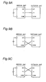
- FIG. 9A is a connection diagram for explaining correct wiring of the air conditioner
- FIG. 9B is a connection diagram for explaining miswiring of the air conditioner
- FIG. 9C is a connection diagram for explaining miswiring of the air conditioner
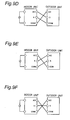
- FIG. 9D is a connection diagram for explaining miswiring of the air conditioner
- FIG. 9E is a connection diagram for explaining miswiring of the air conditioner
- FIG. 9F is a connection diagram for explaining miswiring of the air conditioner
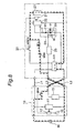
- FIG. 1 is a block diagram of the air conditioner of the first embodiment of the present invention, showing an indoor unit 10, an outdoor unit 20 connected to the indoor unit 10 via connection wiring lines (L1 through L3), and an external power source 30 connected to the outdoor unit 20.
- the indoor unit 10 includes a power circuit 11 that has one terminal connected to the power line L1 and has the other terminal connected to the power line L2, an indoor side transmitting and receiving section 15 as one example of the indoor side transmitting and receiving means that has one terminal connected to one terminal of the signal line L3 and has the other terminal connected to the power line L2, and a relay MR10 as one example of the indoor side switch means connected between the power line L1 and the signal line L3, the relay MR10 being normally in an open state.
- the indoor unit 10 also includes an indoor control section 12 as one example of the indoor control means that is supplied with a power from the power circuit 11 and controls the relay MR10 and so on, and a display section 13 as one example of the informing means controlled by the indoor control section 12.
- a power voltage supplied from the external power source 30 is applied across both terminals of the power circuit 11 via the power lines L1 and L2.
- the outdoor unit 20 includes an EMI filter LC1 that have input terminals (T1 and T2 shown in FIG. 4) connected to the power lines L1 and L2, an outdoor side transmitting and receiving section 25 as one example of the outdoor side transmitting and receiving means connected to the other terminal of the signal line L3, a transmission power circuit 24 that has one terminal connected to the signal line L3 via a switchover relay MR30 and supplies a power to the outdoor side transmitting and receiving section 25, a switching power circuit 22 that has one terminal connected to the signal line L3 via the switchover relay MR30, and a power circuit 23 as one example of the load that has one terminal connected via a relay MRM10 to one terminal (T3 shown in FIG. 4) of the output terminals of the EMI filter LC1.
- the other terminal of the switching power circuit 22 is connected to the other terminal (T4 shown in FIG. 4) of the output terminals of the EMI filter LC1, and the other terminal of the power circuit 23 is connected to the other terminal of the output terminals of the EMI filter LC1 via a relay MRM11.
- a relay MRM20 and a resistor R11 are connected to both terminals of the relay MRM10 serially in order from the EMI filter LC1 side.
- the outdoor unit 20 also includes an outdoor control section 21 as one example of the outdoor control means that is supplied with a power from the switching power circuit 22 and controls the relays MRM10, MRM20, MRM11, MR30 and so on.
- the resistor R11 prevents an overcurrent from flowing through the relay MRM11 and the relay MRM20 when power supply starts from the standby state.
- the switchover relay MR30 has input terminals 1 and 2 and an output terminal 3.
- the input terminal 1 is connected to the signal line L3, the input terminal 2 is connected to one terminal (T3 shown in FIG. 4) of the output terminals of the EMI filter LC1, and the output terminal 3 is connected to one terminal of the switching power circuit 22.
- the switchover relay MR30 which connects the signal line L3 with the transmission power circuit 24 in the OFF state, releases the connection between the signal line L3 and the transmission power circuit 24 in the ON state and connects one (T3 shown in FIG. 4) of the output terminals of the EMI filter LC1 with the transmission power circuit 24.
- the transmission power circuit 24 has a resistor R1 that has one terminal connected to the signal line L3 via a switchover relay MRM30, a diode D1 of which the anode is connected to the other terminal of the resistor R1, a zener diode ZD1 of which the cathode is connected to the cathode of diode D1 and the anode is connected to the power line L2, a smoothing capacitor C1 connected in parallel with the zener diode ZD1, and a resistor R2 connected in parallel with the zener diode ZD1.
- the resistor R2 prevents an overvoltage from being applied across both terminals of the zener diode ZD1 and the smoothing capacitor C1.
- An AC voltage supplied from the power lines L1 and L2 shown in FIG. 1 is half-wave rectified by the diode D1 and smoothed by a smoothing capacitor C1.
- the smoothed DC voltage is regulated to a constant voltage by the zener diode ZD1 and supplied to the outdoor side transmitting and receiving section 25.
- FIG. 2 shows a circuit diagram of the indoor side transmitting and receiving section 15.
- the indoor side transmitting and receiving section 15 includes a diode D151 of which the anode is connected to a terminal 151, a resistor R151 that has one terminal connected to the cathode of the diode D151, a phototransistor Q151 of which the collector is connected to the other terminal of the resistor R151, a light-emitting diode D152 of which the anode is connected to the emitter of the phototransistor Q151 and the cathode is connected to a terminal 152, a zener diode ZD151 of which the cathode is connected to the collector of the phototransistor Q151 and the anode is connected to the emitter of the phototransistor, and a resistor R152 connected in parallel with both terminals of the light-emitting diode D152.
- a photocoupler is constructed of a pair of the phototransistor Q151 and a light-emitting diode (not shown), and a photocoupler is constructed of a pair of the light-emitting diode D152 and a phototransistor (not shown), enabling two-way communications.
- the terminal 151 of the indoor side transmitting and receiving section 15 is connected to the communication line L3, and the terminal 152 is connected to the power line L2.
- the resistor R151 limits the current that flows through the phototransistor Q151 and the light-emitting diode D152, and the diode D151 prevents the current from flowing backward.
- the zener diode ZD151 prevents an overvoltage from being applied across both terminals of the phototransistor Q151, and the resistor R152 prevents an overvoltage from being applied across both terminals of the light-emitting diode D152.
- FIG. 3 shows a circuit diagram of the outdoor side transmitting and receiving section 25.
- the outdoor side transmitting and receiving section 25 includes a diode D251 of which the cathode is connected to a terminal 251, a resistor R251 that has one terminal connected to the anode of the diode D251, a light-emitting diode D252 of which the cathode is connected to the other terminal of the resistor R251, a resistor R252 connected in parallel with both terminals of the light-emitting diode D252, a phototransistor Q251 of which the emitter is connected to the anode of the light-emitting diode D252 and the collector is connected to a terminal 252, a resistor R253 connected between the collector and the emitter of the phototransistor Q251, a zener diode ZD251 of which the anode is connected to the collector of the phototransistor Q251, and a zener diode ZD
- a photocoupler is constructed of a pair of the phototransistor Q251 and a light-emitting diode (not shown), and a photocoupler is constructed of a pair of the light-emitting diode D252 and a phototransistor (not shown), enabling two-way communications.
- the terminal 251 of the outdoor side transmitting and receiving section 25 is connected to the communication line L3, and the terminal 252 is connected to the transmission power circuit 24.
- the diode D251 prevents the current from flowing backward, and the resistor R251 limits the current that flows through the phototransistor Q251 and the light-emitting diode D252.
- the resistor R252 prevents an overvoltage from being applied across both terminals of the light-emitting diode D252, and the resistor R253 prevents an overcurrent from flowing through the phototransistor Q251.
- FIG. 4 shows a circuit diagram of the EMI filter LC1 of the outdoor unit of the air conditioner.
- the EMI filter LC1 has a coil L11 that has one terminal connected to a terminal T1, a coil L12 that has one terminal connected to a terminal T2 and forms a mutual inductance with the coil L11, a coil L13 that has one terminal connected to the other terminal of the coil L11 and has the other terminal connected to a terminal T3, a coil L14 that has one terminal connected to the other terminal of the coil L12 and has the other terminal connected to a terminal T4, a capacitor C12 that has one terminal connected to the other terminal of the coil L13 and has the other terminal grounded, a capacitor C13 that has one terminal connected to the other terminal the coil L14 and has the other terminal connected to the other terminal of the capacitor C12, and a capacitor C11 connected between the terminal T3 and the terminal T4.
- the terminal T1 of the EMI filter LC1 is connected to the power line L1 (shown in FIG. 1), and the terminal T2 is connected to the power line L2 (shown in FIG. 1).
- the terminal T3 is connected to the relays MRM10 and MRM20 (shown in FIG. 1), and the terminal T4 is connected to the switching power circuit 22 and MRM11 (shown in FIG. 1).
- a first noise generated in the power circuit 23 is inputted to the terminal T3 via the power line L1 (shown in FIG. 1) and inputted to the terminal T4 via the power line L2 (shown in FIG. 1).
- the first noise has mainly a low-frequency normal-mode noise and a high-frequency common-mode noise.
- the low-frequency normal-mode noise has its frequency components of not lower than the cutoff frequency removed by the operation of a low-pass filter constructed of the capacitor C11, the coil L13 and the coil L14.
- the high-frequency common-mode noise has its frequency components of not lower than the cutoff frequency removed by the operation of a low-pass filter constructed of the capacitor C12, the capacitor C13, the coil L11 and the coil L12.
- the relay MR10 of the indoor unit 10 is closed by an indoor microcomputer 12 when the operation is switched over from the standby state to the operating state, so that the main power is supplied from the power line L1 to the signal line L3. That is, a rise in the voltage of the signal line L3 serves as a signal of switchover from the standby state to the operating state.
- the indoor control section 12 determines whether or not the connection wiring lines L1 through L3 that connect the indoor unit 10 with the outdoor unit 20 are miswired on the basis of a reception output of the indoor side transmitting and receiving section 15 when the operation starts from the standby state, and does not turn on the relay MRM10 when determining that the wiring lines are miswired.
- FIG. 6 shows a timing chart for explaining the processing when the operation starts from the standby state of the air conditioner.
- FIG. 6(a) shows an operation start signal of the air conditioner
- FIG. 6(b) shows the reception output of the indoor side transmitting and receiving section
- FIG. 6(c) shows the operating state of the relay MR10 in the case of miswiring
- FIG. 6(d) shows the operating state of the relay MR10 when the wiring is correct.
- the indoor control section 12 receives an operation start signal (shown in FIG. 6(a)) and thereafter confirms the reception output of the indoor side transmitting and receiving section 15 after a lapse of a prescribed time (e.g., one second).
- a prescribed time e.g., one second.
- the connection wiring lines are miswired as shown in FIGS. 5A and 5B, the reception output of the indoor side transmitting and receiving section 15 periodically repeats on- and off-states as shown in FIG. 6(b). This is because an AC voltage is applied to the connection wiring line L3 with a closed circuit formed as shown in FIG. 5A so that the diode D151 of the indoor side transmitting and receiving section 15 emits light every half wave (at intervals of 20 milliseconds at a frequency of 50 Hz) of the AC voltage.
- the indoor control section 12 confirms the reception output of the indoor side transmitting and receiving section 15 in cycles of several milliseconds and does not turn on the relay MR10 upon determining that the wiring lines are miswired when high level consecutively appears two times as shown in FIG. 6(c).
- the indoor control section 12 determines that the wiring lines are not miswired since the reception output of the indoor side transmitting and receiving section 15 is not turned on unless communication is carried out, and turns on the relay MR10 for a prescribed time (e.g., several tens of milliseconds) as shown in FIG. 6(d).
- the indoor control section 12 Upon determining that the wiring lines are miswired on the basis of the reception output of the indoor side transmitting and receiving section 15, the indoor control section 12 informs the user of the miswiring by means of the display section 13.
- connection wiring lines (L1 through L3) that connect the indoor unit 10 with the outdoor unit 20 are miswired.
- connection wiring lines (L1 through L3) are miswired before the relay MR10 is turned on by the fact that the reception output of the indoor side transmitting and receiving section 15 is turned on as a consequence of applying the power voltage to the signal line L3 in the miswired state shown in FIG. 5A.
- connection wiring lines (L1 through L3) are miswired, the operator is able to perceive the cause of the trouble at the time of installation and to swiftly cope with the trouble.
- FIG. 7 is a block diagram of the air conditioner of the second embodiment of the present invention, showing an indoor unit 10, an outdoor unit 20 connected to the indoor unit 10 via connection wiring lines (L1 through L3), and an external power source 30 connected to the indoor unit 10.
- the indoor unit 10 includes a power circuit 11 that has one terminal connected to a power line L1 and has the other terminal connected to a power line L2, an indoor side transmitting and receiving section 15 as one example of the indoor side transmitting and receiving means that has one terminal connected to one terminal of a signal line L3 and has the other terminal connected to the power line L2, and a relay MR10 as one example of the indoor side switch means that is normally in an open state and connected between the power line L1 and the signal line L3.
- a power voltage supplied from the external power source 30 is applied across both terminals of the power circuit 11.
- the indoor unit 10 also includes an indoor control section 12 as one example of the indoor control means that is supplied with a power from a power circuit 11 and controls the relay MR10 and so on, and a display section 13 as one example of the informing means controlled by the indoor control section 12.
- an indoor control section 12 as one example of the indoor control means that is supplied with a power from a power circuit 11 and controls the relay MR10 and so on
- a display section 13 as one example of the informing means controlled by the indoor control section 12.
- the outdoor unit 20 includes an EMI filter LC1 that have input terminals connected to the power lines L1 and L2, an outdoor side transmitting and receiving section 25 as one example of the outdoor side transmitting and receiving means connected to the other terminal of the signal line L3, a transmission power circuit 24 that supplies a power to the outdoor side transmitting and receiving section 25, a switching power circuit 22 connected to one terminal of the output terminals of the EMI filter LC1 via a relay MRM10 as one example of the operating power supply switch means, and a power circuit 23 as one example of the load that has one terminal connected to one terminal of the switching power circuit 22.
- the outdoor unit 20 also includes an outdoor control section 21 as one example of the outdoor control means that is supplied with a power from the switching power circuit 22 and controls the relay MRM10 and so on.
- the indoor side transmitting and receiving section 15, the transmission power circuit 24, the outdoor side transmitting and receiving section 25 and the EMI filter LC1 have identical structures as those of the air conditioner of the first embodiment, and no description is provided for them.
- the relay MR10 of the indoor unit 10 is closed by an indoor microcomputer 12 when the operation is switched over from the standby state to the operating state, so that the main power is supplied from the power line L1 to the signal line L3. That is, the structure is similar to that of the first embodiment in the point that the signal representing switchover from the standby state to the operating state is a rise in the voltage of the signal line L3.
- the outdoor control section 21 brings the startup relay MR30 into the closed state and thereafter turns on the relay MRM10 after a lapse of a prescribed time (e.g., several tens of milliseconds) when the operation starts from the standby state upon supplying a power for startup from the indoor unit 10 side via the signal line L3 by turning on the relay MR10 of the indoor unit 10.
- a prescribed time e.g., several tens of milliseconds
- the relay MR10 of the indoor unit 10 when the relay MR10 of the indoor unit 10 is turned on, an AC voltage is applied to the signal line L3, so that a power is supplied to the switching power circuit 22 via the switchover relay MR30 and the resistor R11 of the outdoor unit 20. Then, a DC voltage is outputted from the switching power circuit 22 to the transmission power circuit 24 and the outdoor control section 21.
- the outdoor control section 21 that operates upon receiving the DC voltage from the switching power circuit 22 brings the startup relay MR30 into the closed state and thereafter turns on the relay MRM10 before the DC voltage output of the switching power circuit 22 is spent and after a lapse of a prescribed time (e.g., several tens of milliseconds). By so doing, the power for operation from the indoor unit 10 side is supplied to the switching power circuit 22 and the power circuit 23 via the power lines L1 and L2.
- connection wiring lines (L1 through L3) that connect the indoor unit 10 with the outdoor unit 20 are miswired.
- the indoor control section 12 determines that the connection wiring lines (L1 through L3) are miswired and informs the user of the miswiring by means of the display section 13. Therefore, the operator is able to perceive the cause of trouble at the time of installation and to swiftly cope with the trouble.
- the external power source 30 is connected to the indoor unit 10 in the second embodiment, the external power source may be connected to the outdoor unit.
- the informing means is not limited to this and allowed to give information by means of a voice sound or a buzzer sound.
Landscapes
- Engineering & Computer Science (AREA)
- Chemical & Material Sciences (AREA)
- Combustion & Propulsion (AREA)
- Mechanical Engineering (AREA)
- General Engineering & Computer Science (AREA)
- Human Computer Interaction (AREA)
- Air Conditioning Control Device (AREA)
Abstract
Description
- The present invention relates to an air conditioner having an indoor unit and an outdoor unit connected via connection wiring.
- Conventionally, there has been proposed an air conditioner, which is externally supplied with a power by an outdoor unit and able to reduce the power consumption in a standby state of an indoor unit and the outdoor unit by limiting the supply of a main power to each part via a power line in the standby state (refer to, for example,
JP 2000-111123 A - Since the transmission of the transmission signal via the signal line has been performed by an AC power in the conventional air conditioner, its transmission speed depends on the frequency and tends to have difficulties in being increased in speed. On the other hand, it has been concerned that, when a power supply is newly provided to increase the speed of the transmission of the transmission signal via the signal line, the power consumptions in the standby state of the indoor unit and the outdoor unit be increased due to the provision of the power supply.
- Accordingly, in order to solve such a problem, the present applicant has proposed an air conditioner and a control method capable of transmitting the transmission signal at high speed and reducing the power consumption in the standby state of the indoor unit and the outdoor unit. It is noted that the air conditioner and the control method are intended for easy understanding of the present invention and neither a known art nor a prior art.
- In the air conditioner, a relay is provided between one of power lines that connect the indoor unit with the outdoor unit and the signal line, and an operating power supply relay of the outdoor unit is turned on by transmitting a power for startup to the outdoor unit using the signal line by turning on the relay for a prescribed time when the operation starts from the standby state in which the power of the outdoor unit is cut off.
- However, it is sometimes the case where, when the connection wires are miswired by mistake in connecting the indoor unit with the outdoor unit by connection wiring lines in the air conditioner, a closed circuit including a power source is formed between a part on the indoor unit side and a part on the outdoor unit side, and this disadvantageously leads to the damage of components.
- Accordingly, it is an object of the present invention to provide an air conditioner capable of preventing the damage of components with a simple construction even when the operation starts in a state in which the connection wiring lines that connect the indoor unit with the outdoor unit are miswired.
- In order to achieve the above object, an air conditioner according to the first inventive aspect comprises:
- an indoor unit and an outdoor unit which are connected via connection wiring;
- the connection wiring comprising two power lines for supplying a power from an external power source to the indoor unit via the outdoor unit, and one signal line for carrying out communication between the indoor unit and the outdoor unit;
- the indoor unit comprising an indoor side transmitting and receiving means which is connected to the signal line and employs a photocoupler, an indoor side switch means which is connected between one of the power lines and the signal line and brought into a closed state at a startup time when operation starts from a standby state in which the supply of power of the outdoor unit is stopped, and an indoor control means which controls the indoor side switch means; and
- the outdoor unit comprising an outdoor side transmitting and receiving means which is connected to the signal line and employs a photocoupler, and a load which is supplied with a power from the two power lines of the connection wiring, wherein
- the indoor control means of the indoor unit does not bring the indoor side switch means into the closed state upon determining that the connection wiring lines which connect the indoor unit with the outdoor unit are miswired on the basis of a reception output of the indoor side transmitting and receiving means when the operation starts from the standby state.
- For example, in a case where the connection wiring lines are connected partially exchanged by connecting the terminal to which the signal line of the indoor unit should be connected with the terminal to which the other of the power lines of the outdoor unit should be connected and connecting the terminal to which the signal line of the outdoor unit should be connected with the terminal to which the other of the power lines of the indoor unit should be connected, a closed circuit is formed of part of the indoor unit, part of the outdoor unit and the power source via the indoor side switch means when the indoor side switch means is directly brought into the closed state at the startup time when the operation starts from the standby state in which the power supply of the outdoor unit is stopped, and an overcurrent flows through the circuit, disadvantageously damaging the components. In contrast to this, according to the air conditioner of the above construction, the indoor control means of the indoor unit determines that the connection wiring lines which connect the indoor unit with the outdoor unit are miswired on the basis of the reception output of the indoor side transmitting and receiving means when the operation starts from the standby state in the miswired state as described above. That is, in the case of the miswiring as described above, it becomes possible to determine that the connection wiring lines are miswired before the indoor side switch means is brought into the closed state by applying the power voltage to the signal line to turn on the reception output of the indoor side transmitting and receiving means. Therefore, even if the operation starts in the state in which the connection wiring lines that connect the indoor unit with the outdoor unit are miswired, the damage of components can be prevented with a simple construction employing the indoor side transmitting and receiving means.
- In the air conditioner of one embodiment, the indoor control means of the indoor unit determines that the connection wiring lines which connect the indoor unit with the outdoor unit are miswired when the reception output of the indoor side transmitting and receiving means is turned on at the time of starting the operation from the standby state in which the supply of power of the outdoor unit is stopped.
- According to the air conditioner of the above embodiment, it becomes possible to easily determine that the connection wiring lines are miswired before the indoor side switch means is brought into the closed state by applying the power voltage to the signal line to turn on the reception output of the indoor side transmitting and receiving means in the miswired state as described above.
- In the air conditioner of one embodiment,
the indoor unit comprises an informing means for informing a user of miswiring, and
the indoor control means informs the user of miswiring by the informing means upon determining that the connection wiring lines which connect the indoor unit with the outdoor unit are miswired. - According to the air conditioner of the above embodiment, the informing means informs the user of the miswiring upon determining that the connection wiring lines are miswired. Therefore, the operator is able to perceive the cause of the trouble at the time of installation and to swiftly cope with the trouble.
- In order to achieve the above object, an air conditioner according to the second inventive aspect comprises:
an indoor unit and an outdoor unit which are connected via connection wiring;
the connection wiring comprising two power lines for supplying a power from an external power source via one of the indoor unit and the outdoor unit to the other of the indoor unit and the outdoor unit, and one signal line for carrying out communication between the indoor unit and the outdoor unit;
the indoor unit comprising an indoor side switch means which is connected between one of the power lines and the signal line and brought into a closed state at a startup time when operation starts from a standby state in which the supply of power of the outdoor unit is stopped, and
the outdoor unit comprising a startup power supply switch means which is brought into a closed state so that a power for startup is supplied from the indoor unit side via the signal line when the indoor side switch means of the indoor unit is brought into the closed state, an operating power supply switch means which is brought into a closed state so that the power for operation is supplied to a load via the power line in operation while is brought into an open state in the standby state, and an outdoor control means which controls the operating power supply switch means (MRM10) and the startup power supply switch means, wherein
the outdoor control means of the outdoor unit brings the startup power supply switch means into the closed state when the operation starts from the standby state by supplying a power for startup from the indoor unit side via the signal line and the startup power supply switch means as a consequence that the indoor side switch means of the indoor unit is brought into the closed state and thereafter brings the operating power supply switch means into the closed state after a lapse of a prescribed time. - For example, in a case where the connection wiring lines are connected partially exchanged by connecting the terminal to which the signal line of the indoor unit should be connected with the terminal to which the other of the power lines of the outdoor unit should be connected and connecting the terminal to which the signal line of the outdoor unit should be connected with the terminal to which the other of the power lines of the indoor unit should be connected, a closed circuit is formed of part of the indoor unit, part of the outdoor unit (including the operating power supply switch means and the startup power supply switch means) and the power source via the indoor side switch means when the indoor side switch means is directly brought into the closed state at the startup time when the operation starts from the standby state in which the power supply of the outdoor unit is stopped, and an overcurrent flows through the circuit, disadvantageously damaging the components. In contrast to this, according to the air conditioner of the above construction, the operating power supply switch means is brought into the closed state after a lapse of the prescribed time after the startup power supply switch means is brought into the open state by the outdoor control means of the outdoor unit when the operation starts from the standby state by supplying the power for the startup from the indoor unit side to the outdoor unit side via the indoor side switch means and the signal line as a consequence that the indoor side switch means of the indoor unit is brought into the closed state. That is, by bringing the startup power supply switch means into the open state before the operating power supply switch means is brought into the closed state, no closed circuit is formed of part of the indoor unit and part of the outdoor unit via the indoor side switch means. Therefore, even when the operation starts in the state in which the connection wiring lines that connect the indoor unit with the outdoor unit are miswired, damage of the components can be prevented with a simple construction.
- In the air conditioner of one embodiment,
the indoor unit comprises an indoor side transmitting and receiving means connected to the signal line; an indoor control means which controls the indoor side switch means and the indoor side transmitting and receiving means, and an informing means for informing a user of miswiring,
the outdoor unit comprises an outdoor side transmitting and receiving means which is connected to the signal line and carries out communication with the indoor side transmitting and receiving means, and
the indoor control means determines that the connection wiring lines which connect the indoor unit with the outdoor unit are miswired when no communication with the outdoor side transmitting and receiving means can be achieved by the indoor side transmitting and receiving means after bringing the indoor side switch means (MR10) into the closed state to start operation from the standby state and informs the user of miswiring by the informing means. - According to the air conditioner of the above embodiment, when no communication with the outdoor side transmitting and receiving means can be achieved by the indoor side transmitting and receiving means after the indoor side switch means is brought into the closed state, the indoor control means determines that the connection wiring lines are miswired and informs the user of the miswiring by the informing means. Therefore, the operator is able to perceive the cause of the trouble at the time of installation and to swiftly cope with the trouble.
- As is apparent from the above, according to the air conditioner of the first inventive aspect, the indoor control means of the indoor unit determines that the connection wiring lines which connect the indoor unit with the outdoor unit are miswired on the basis of the reception output of the indoor side transmitting and receiving means when the operation starts from the standby state in the miswired state and does not bring the indoor side switch means into the closed state. With this arrangement, damage of the components can be prevented with a simple construction even when the operation starts in the miswiring state in which the connection wiring lines which connect the indoor unit with the outdoor unit are miswired.
- Moreover, according to the air conditioner of the above embodiment, it becomes possible to easily determine that the connection wiring lines are miswired before the indoor side switch means is brought into the closed state by applying the power voltage to the signal line to turn on the reception output of the indoor side transmitting and receiving means in the miswired state as described above.
- Moreover, according to the air conditioner of one embodiment, by informing the user of the miswiring by the informing means when the indoor control means determines that the connection wiring lines are miswired, the operator is able to perceive the cause of the trouble at the time of installation and to swiftly cope with the trouble.
- Moreover, according to the air conditioner of the second inventive aspect, the operating power supply switch means is brought into the closed state after a lapse of the prescribed time after the startup power supply switch means is brought into the open state by the outdoor control means of the outdoor unit when the operation starts from the standby state by supplying the power for the startup from the indoor unit side to the outdoor unit side via the indoor side switch means and the signal line as a consequence that the indoor side switch means of the indoor unit is brought into the closed state. Therefore, even when the operation starts in the state in which the connection wiring lines that connect the indoor unit with the outdoor unit are miswired, damage of the components can be prevented with a simple construction.
- Moreover, according to the air conditioner of one embodiment, when no communication with the outdoor side transmitting and receiving means can be achieved by the indoor side transmitting and receiving means after the indoor side switch means is brought into the closed state, the indoor control means determines that the connection wiring lines are miswired and informs the user of the miswiring by the informing means. With this arrangement, the operator is able to perceive the cause of the trouble at the time of installation and to swiftly cope with the trouble.
- The present invention will become more fully understood from the detailed description given hereinbelow and the accompanying drawings which are given by way of illustration only, and thus are not limitative of the present invention, and wherein:
- FIG. 1 is a block diagram of an air conditioner according to a first embodiment of the present invention;
- FIG. 2 is a circuit diagram of an indoor side transmitting and receiving section of the air conditioner;
- FIG. 3 is a circuit diagram of an outdoor side transmitting and receiving section of the air conditioner;
- FIG. 4 is a circuit diagram of an EMI filter of an outdoor unit of the air conditioner;
- FIG. 5A is a connection diagram in a case of miswiring of the air conditioner;
- FIG. 5B is a diagram showing a state when a MR10 is turned on in the case of miswiring of the air conditioner;
- FIG. 6 is a timing chart showing processing when the air conditioner starts operating from a standby state;
- FIG. 7 is a block diagram of an air conditioner according to a second embodiment of the present invention ;
- FIG. 8 is a connection diagram in a case of miswiring of the air conditioner;
- FIG. 9A is a connection diagram for explaining correct wiring of the air conditioner;
- FIG. 9B is a connection diagram for explaining miswiring of the air conditioner;
- FIG. 9C is a connection diagram for explaining miswiring of the air conditioner;
- FIG. 9D is a connection diagram for explaining miswiring of the air conditioner;
- FIG. 9E is a connection diagram for explaining miswiring of the air conditioner;
- FIG. 9F is a connection diagram for explaining miswiring of the air conditioner;
- The air conditioner of the present invention will now be described in detail below by the embodiments shown in the drawings.
- FIG. 1 is a block diagram of the air conditioner of the first embodiment of the present invention, showing an
indoor unit 10, anoutdoor unit 20 connected to theindoor unit 10 via connection wiring lines (L1 through L3), and anexternal power source 30 connected to theoutdoor unit 20. - The
indoor unit 10 includes a power circuit 11 that has one terminal connected to the power line L1 and has the other terminal connected to the power line L2, an indoor side transmitting and receivingsection 15 as one example of the indoor side transmitting and receiving means that has one terminal connected to one terminal of the signal line L3 and has the other terminal connected to the power line L2, and a relay MR10 as one example of the indoor side switch means connected between the power line L1 and the signal line L3, the relay MR10 being normally in an open state. Theindoor unit 10 also includes anindoor control section 12 as one example of the indoor control means that is supplied with a power from the power circuit 11 and controls the relay MR10 and so on, and adisplay section 13 as one example of the informing means controlled by theindoor control section 12. A power voltage supplied from theexternal power source 30 is applied across both terminals of the power circuit 11 via the power lines L1 and L2. - On the other hand, the
outdoor unit 20 includes an EMI filter LC1 that have input terminals (T1 and T2 shown in FIG. 4) connected to the power lines L1 and L2, an outdoor side transmitting and receivingsection 25 as one example of the outdoor side transmitting and receiving means connected to the other terminal of the signal line L3, atransmission power circuit 24 that has one terminal connected to the signal line L3 via a switchover relay MR30 and supplies a power to the outdoor side transmitting and receivingsection 25, a switchingpower circuit 22 that has one terminal connected to the signal line L3 via the switchover relay MR30, and apower circuit 23 as one example of the load that has one terminal connected via a relay MRM10 to one terminal (T3 shown in FIG. 4) of the output terminals of the EMI filter LC1. The other terminal of the switchingpower circuit 22 is connected to the other terminal (T4 shown in FIG. 4) of the output terminals of the EMI filter LC1, and the other terminal of thepower circuit 23 is connected to the other terminal of the output terminals of the EMI filter LC1 via a relay MRM11. Moreover, a relay MRM20 and a resistor R11 are connected to both terminals of the relay MRM10 serially in order from the EMI filter LC1 side. Theoutdoor unit 20 also includes anoutdoor control section 21 as one example of the outdoor control means that is supplied with a power from the switchingpower circuit 22 and controls the relays MRM10, MRM20, MRM11, MR30 and so on. The resistor R11 prevents an overcurrent from flowing through the relay MRM11 and the relay MRM20 when power supply starts from the standby state. - The switchover relay MR30 has
input terminals input terminal 1 is connected to the signal line L3, theinput terminal 2 is connected to one terminal (T3 shown in FIG. 4) of the output terminals of the EMI filter LC1, and the output terminal 3 is connected to one terminal of the switchingpower circuit 22. The switchover relay MR30, which connects the signal line L3 with thetransmission power circuit 24 in the OFF state, releases the connection between the signal line L3 and thetransmission power circuit 24 in the ON state and connects one (T3 shown in FIG. 4) of the output terminals of the EMI filter LC1 with thetransmission power circuit 24. - The
transmission power circuit 24 has a resistor R1 that has one terminal connected to the signal line L3 via a switchover relay MRM30, a diode D1 of which the anode is connected to the other terminal of the resistor R1, a zener diode ZD1 of which the cathode is connected to the cathode of diode D1 and the anode is connected to the power line L2, a smoothing capacitor C1 connected in parallel with the zener diode ZD1, and a resistor R2 connected in parallel with the zener diode ZD1. The resistor R2 prevents an overvoltage from being applied across both terminals of the zener diode ZD1 and the smoothing capacitor C1. - An AC voltage supplied from the power lines L1 and L2 shown in FIG. 1 is half-wave rectified by the diode D1 and smoothed by a smoothing capacitor C1. The smoothed DC voltage is regulated to a constant voltage by the zener diode ZD1 and supplied to the outdoor side transmitting and receiving
section 25. - FIG. 2 shows a circuit diagram of the indoor side transmitting and receiving
section 15. As shown in FIG. 2, the indoor side transmitting and receivingsection 15 includes a diode D151 of which the anode is connected to a terminal 151, a resistor R151 that has one terminal connected to the cathode of the diode D151, a phototransistor Q151 of which the collector is connected to the other terminal of the resistor R151, a light-emitting diode D152 of which the anode is connected to the emitter of the phototransistor Q151 and the cathode is connected to a terminal 152, a zener diode ZD151 of which the cathode is connected to the collector of the phototransistor Q151 and the anode is connected to the emitter of the phototransistor, and a resistor R152 connected in parallel with both terminals of the light-emitting diode D152. Moreover, in the indoor side transmitting and receivingsection 15, a photocoupler is constructed of a pair of the phototransistor Q151 and a light-emitting diode (not shown), and a photocoupler is constructed of a pair of the light-emitting diode D152 and a phototransistor (not shown), enabling two-way communications. Theterminal 151 of the indoor side transmitting and receivingsection 15 is connected to the communication line L3, and the terminal 152 is connected to the power line L2. - The resistor R151 limits the current that flows through the phototransistor Q151 and the light-emitting diode D152, and the diode D151 prevents the current from flowing backward. The zener diode ZD151 prevents an overvoltage from being applied across both terminals of the phototransistor Q151, and the resistor R152 prevents an overvoltage from being applied across both terminals of the light-emitting diode D152.
- FIG. 3 shows a circuit diagram of the outdoor side transmitting and receiving
section 25. As shown in FIG. 3, the outdoor side transmitting and receivingsection 25 includes a diode D251 of which the cathode is connected to a terminal 251, a resistor R251 that has one terminal connected to the anode of the diode D251, a light-emitting diode D252 of which the cathode is connected to the other terminal of the resistor R251, a resistor R252 connected in parallel with both terminals of the light-emitting diode D252, a phototransistor Q251 of which the emitter is connected to the anode of the light-emitting diode D252 and the collector is connected to a terminal 252, a resistor R253 connected between the collector and the emitter of the phototransistor Q251, a zener diode ZD251 of which the anode is connected to the collector of the phototransistor Q251, and a zener diode ZD252 of which the anode is connected to the cathode of the zener diode ZD251 and the cathode is connected to the emitter of the phototransistor Q251. Moreover, in the indoor side transmitting and receivingsection 15, a photocoupler is constructed of a pair of the phototransistor Q251 and a light-emitting diode (not shown), and a photocoupler is constructed of a pair of the light-emitting diode D252 and a phototransistor (not shown), enabling two-way communications. Theterminal 251 of the outdoor side transmitting and receivingsection 25 is connected to the communication line L3, and the terminal 252 is connected to thetransmission power circuit 24. - The diode D251 prevents the current from flowing backward, and the resistor R251 limits the current that flows through the phototransistor Q251 and the light-emitting diode D252. The resistor R252 prevents an overvoltage from being applied across both terminals of the light-emitting diode D252, and the resistor R253 prevents an overcurrent from flowing through the phototransistor Q251.
- FIG. 4 shows a circuit diagram of the EMI filter LC1 of the outdoor unit of the air conditioner. As shown in FIG. 4, the EMI filter LC1 has a coil L11 that has one terminal connected to a terminal T1, a coil L12 that has one terminal connected to a terminal T2 and forms a mutual inductance with the coil L11, a coil L13 that has one terminal connected to the other terminal of the coil L11 and has the other terminal connected to a terminal T3, a coil L14 that has one terminal connected to the other terminal of the coil L12 and has the other terminal connected to a terminal T4, a capacitor C12 that has one terminal connected to the other terminal of the coil L13 and has the other terminal grounded, a capacitor C13 that has one terminal connected to the other terminal the coil L14 and has the other terminal connected to the other terminal of the capacitor C12, and a capacitor C11 connected between the terminal T3 and the terminal T4.
- The terminal T1 of the EMI filter LC1 is connected to the power line L1 (shown in FIG. 1), and the terminal T2 is connected to the power line L2 (shown in FIG. 1). The terminal T3 is connected to the relays MRM10 and MRM20 (shown in FIG. 1), and the terminal T4 is connected to the switching
power circuit 22 and MRM11 (shown in FIG. 1). - In the EMI filter LC1, a first noise generated in the power circuit 23 (shown in FIG. 1) is inputted to the terminal T3 via the power line L1 (shown in FIG. 1) and inputted to the terminal T4 via the power line L2 (shown in FIG. 1). The first noise has mainly a low-frequency normal-mode noise and a high-frequency common-mode noise. The low-frequency normal-mode noise has its frequency components of not lower than the cutoff frequency removed by the operation of a low-pass filter constructed of the capacitor C11, the coil L13 and the coil L14. On the other hand, the high-frequency common-mode noise has its frequency components of not lower than the cutoff frequency removed by the operation of a low-pass filter constructed of the capacitor C12, the capacitor C13, the coil L11 and the coil L12.
- As shown in FIG. 1, with regard to the relay MR10 of the
indoor unit 10, the relay MR10 is closed by anindoor microcomputer 12 when the operation is switched over from the standby state to the operating state, so that the main power is supplied from the power line L1 to the signal line L3. That is, a rise in the voltage of the signal line L3 serves as a signal of switchover from the standby state to the operating state. - In the air conditioner of the above construction, it is correct to connect the wiring lines L1 through L3 at the time of installation in a manner that the terminals AC, terminals S and terminals COM of the
indoor unit 10 andoutdoor unit 20 are mutually connected as shown in FIGS. 1 and 9A. However, five misconnection cases shown in FIGS. 9B through 9F are possible. Among others, in the case of the misconnection shown in FIG. 9B, when the relay MR10 is turned on as indicated by the dashed lines in FIG. 5B, a closed circuit including theexternal power source 30 is formed to damage the components (for example, the relay MR10). In the misconnection cases of FIGS. 9C through 9F, no closed circuit including the power source is formed, and the components are not damaged. - Accordingly, in the air conditioner of the first embodiment, the
indoor control section 12 determines whether or not the connection wiring lines L1 through L3 that connect theindoor unit 10 with theoutdoor unit 20 are miswired on the basis of a reception output of the indoor side transmitting and receivingsection 15 when the operation starts from the standby state, and does not turn on the relay MRM10 when determining that the wiring lines are miswired. - FIG. 6 shows a timing chart for explaining the processing when the operation starts from the standby state of the air conditioner. Referring to FIG. 6, FIG. 6(a) shows an operation start signal of the air conditioner, FIG. 6(b) shows the reception output of the indoor side transmitting and receiving
section 15, FIG. 6(c) shows the operating state of the relay MR10 in the case of miswiring, and FIG. 6(d) shows the operating state of the relay MR10 when the wiring is correct. - As shown in FIG. 6, when the operation is first started by manipulating a remote controller (not shown) of the
indoor unit 10 in the standby state (during operation stop), theindoor control section 12 receives an operation start signal (shown in FIG. 6(a)) and thereafter confirms the reception output of the indoor side transmitting and receivingsection 15 after a lapse of a prescribed time (e.g., one second). At this time, if the connection wiring lines are miswired as shown in FIGS. 5A and 5B, the reception output of the indoor side transmitting and receivingsection 15 periodically repeats on- and off-states as shown in FIG. 6(b). This is because an AC voltage is applied to the connection wiring line L3 with a closed circuit formed as shown in FIG. 5A so that the diode D151 of the indoor side transmitting and receivingsection 15 emits light every half wave (at intervals of 20 milliseconds at a frequency of 50 Hz) of the AC voltage. - The
indoor control section 12 confirms the reception output of the indoor side transmitting and receivingsection 15 in cycles of several milliseconds and does not turn on the relay MR10 upon determining that the wiring lines are miswired when high level consecutively appears two times as shown in FIG. 6(c). When the wiring lines are correctly wired, theindoor control section 12 determines that the wiring lines are not miswired since the reception output of the indoor side transmitting and receivingsection 15 is not turned on unless communication is carried out, and turns on the relay MR10 for a prescribed time (e.g., several tens of milliseconds) as shown in FIG. 6(d). - Upon determining that the wiring lines are miswired on the basis of the reception output of the indoor side transmitting and receiving
section 15, theindoor control section 12 informs the user of the miswiring by means of thedisplay section 13. - According to the air conditioner of the first embodiment, damage of the components can be prevented with a simple construction even if the operation starts in the state in which the connection wiring lines (L1 through L3) that connect the
indoor unit 10 with theoutdoor unit 20 are miswired. - Moreover, it becomes possible to easily determine that the connection wiring lines (L1 through L3) are miswired before the relay MR10 is turned on by the fact that the reception output of the indoor side transmitting and receiving
section 15 is turned on as a consequence of applying the power voltage to the signal line L3 in the miswired state shown in FIG. 5A. - Moreover, since the user is informed of the miswiring by the
display section 13 when theindoor control section 12 determines that the connection wiring lines (L1 through L3) are miswired, the operator is able to perceive the cause of the trouble at the time of installation and to swiftly cope with the trouble. - FIG. 7 is a block diagram of the air conditioner of the second embodiment of the present invention, showing an
indoor unit 10, anoutdoor unit 20 connected to theindoor unit 10 via connection wiring lines (L1 through L3), and anexternal power source 30 connected to theindoor unit 10. - The
indoor unit 10 includes a power circuit 11 that has one terminal connected to a power line L1 and has the other terminal connected to a power line L2, an indoor side transmitting and receivingsection 15 as one example of the indoor side transmitting and receiving means that has one terminal connected to one terminal of a signal line L3 and has the other terminal connected to the power line L2, and a relay MR10 as one example of the indoor side switch means that is normally in an open state and connected between the power line L1 and the signal line L3. A power voltage supplied from theexternal power source 30 is applied across both terminals of the power circuit 11. Theindoor unit 10 also includes anindoor control section 12 as one example of the indoor control means that is supplied with a power from a power circuit 11 and controls the relay MR10 and so on, and adisplay section 13 as one example of the informing means controlled by theindoor control section 12. - On the other hand, the
outdoor unit 20 includes an EMI filter LC1 that have input terminals connected to the power lines L1 and L2, an outdoor side transmitting and receivingsection 25 as one example of the outdoor side transmitting and receiving means connected to the other terminal of the signal line L3, atransmission power circuit 24 that supplies a power to the outdoor side transmitting and receivingsection 25, a switchingpower circuit 22 connected to one terminal of the output terminals of the EMI filter LC1 via a relay MRM10 as one example of the operating power supply switch means, and apower circuit 23 as one example of the load that has one terminal connected to one terminal of the switchingpower circuit 22. One terminal of a switchover relay MR30 as one example of the startup power supply switch means is connected to the signal line L3, and the other terminal of the switchover relay MR30 is connected to one terminal of the resistor R11. The other terminal of the resistor R11 is connected to a connection point of the relay MRM10 and the switchingpower circuit 22. Moreover, the other terminal of the switchingpower circuit 22 and the other terminal of thepower circuit 23 are connected to the other terminal of the output terminals of the EMI filter LC1. Theoutdoor unit 20 also includes anoutdoor control section 21 as one example of the outdoor control means that is supplied with a power from the switchingpower circuit 22 and controls the relay MRM10 and so on. - The indoor side transmitting and receiving
section 15, thetransmission power circuit 24, the outdoor side transmitting and receivingsection 25 and the EMI filter LC1 have identical structures as those of the air conditioner of the first embodiment, and no description is provided for them. - As shown in FIG. 8, with regard to the relay MR10 of the
indoor unit 10, the relay MR10 is closed by anindoor microcomputer 12 when the operation is switched over from the standby state to the operating state, so that the main power is supplied from the power line L1 to the signal line L3. That is, the structure is similar to that of the first embodiment in the point that the signal representing switchover from the standby state to the operating state is a rise in the voltage of the signal line L3. - In the air conditioner of the above construction, it is correct to connect the wiring lines L1 through L3 at the time of installation in a manner that the terminals AC, the terminals S and the terminals COM are mutually connected as shown in FIGS. 7 and 9A. However, five misconnection cases shown in FIGS. 9B through 9F are possible. Among others, in the case of the misconnection shown in FIG. 9B, the components are to be damaged.
- Accordingly, in the air conditioner of the second embodiment, the
outdoor control section 21 brings the startup relay MR30 into the closed state and thereafter turns on the relay MRM10 after a lapse of a prescribed time (e.g., several tens of milliseconds) when the operation starts from the standby state upon supplying a power for startup from theindoor unit 10 side via the signal line L3 by turning on the relay MR10 of theindoor unit 10. - In detail, when the relay MR10 of the
indoor unit 10 is turned on, an AC voltage is applied to the signal line L3, so that a power is supplied to the switchingpower circuit 22 via the switchover relay MR30 and the resistor R11 of theoutdoor unit 20. Then, a DC voltage is outputted from the switchingpower circuit 22 to thetransmission power circuit 24 and theoutdoor control section 21. As a result, theoutdoor control section 21 that operates upon receiving the DC voltage from the switchingpower circuit 22 brings the startup relay MR30 into the closed state and thereafter turns on the relay MRM10 before the DC voltage output of the switchingpower circuit 22 is spent and after a lapse of a prescribed time (e.g., several tens of milliseconds). By so doing, the power for operation from theindoor unit 10 side is supplied to the switchingpower circuit 22 and thepower circuit 23 via the power lines L1 and L2. - According to the air conditioner of the second embodiment, damage of the components can be prevented with a simple construction even if the operation starts in the state in which the connection wiring lines (L1 through L3) that connect the
indoor unit 10 with theoutdoor unit 20 are miswired. - Moreover, when no communication with the outdoor side transmitting and receiving
section 25 can be achieved by the indoor side transmitting and receivingsection 15 after the relay MR10 is turned on, theindoor control section 12 determines that the connection wiring lines (L1 through L3) are miswired and informs the user of the miswiring by means of thedisplay section 13. Therefore, the operator is able to perceive the cause of trouble at the time of installation and to swiftly cope with the trouble. - Although the
external power source 30 is connected to theindoor unit 10 in the second embodiment, the external power source may be connected to the outdoor unit. - Moreover, although the
display section 13 is employed as the informing means in the first and second embodiments, the informing means is not limited to this and allowed to give information by means of a voice sound or a buzzer sound. - The invention being thus described, it will be obvious that the same may be varied in many ways. Such variations are not to be regarded as a departure from the spirit and scope of the invention, and all such modifications as would be obvious to one skilled in the art are intended to be included within the scope of the following claims.
Claims (5)
- An air conditioner comprising:an indoor unit (10) and an outdoor unit (20) which are connected via connection wiring;the connection wiring comprising two power lines (L1, L2) for supplying a power from an external power source to the indoor unit (10) via the outdoor unit (20), and one signal line (L3) for carrying out communication between the indoor unit (10) and the outdoor unit (20);the indoor unit (10) comprising an indoor side transmitting and receiving means (15) which is connected to the signal line (L3) and employs a photocoupler, an indoor side switch means (MR10) which is connected between one (L1) of the power lines and the signal line (L3) and brought into a closed state at a startup time when operation starts from a standby state in which the supply of power of the outdoor unit (20) is stopped, and an indoor control means (12) which controls the indoor side switch means (MR10); andthe outdoor unit (20) comprising an outdoor side transmitting and receiving means (25) which is connected to the signal line (L3) and employs a photocoupler, and a load (23) which is supplied with a power from the two power lines (L1, L2) of the connection wiring, whereinthe indoor control means (12) of the indoor unit (10) does not bring the indoor side switch means (MR10) into the closed state upon determining that the connection wiring lines which connect the indoor unit (10) with the outdoor unit (20) are miswired on the basis of a reception output of the indoor side transmitting and receiving means (15) when the operation starts from the standby state.
- The air conditioner as claimed in claim 1, wherein the indoor control means (12) of the indoor unit (10) determines that the connection wiring lines which connect the indoor unit (10) with the outdoor unit (20) are miswired when the reception output of the indoor side transmitting and receiving means (15) is turned on at the time of starting the operation from the standby state in which the supply of power of the outdoor unit (20) is stopped.
- The air conditioner as claimed in claim 1, wherein the indoor unit (10) comprises an informing means (13) for informing a user of miswiring, and
the indoor control means (12) informs the user of miswiring by the informing means (13) upon determining that the connection wiring lines which connect the indoor unit (10) with the outdoor unit (20) are miswired. - An air conditioner comprising:an indoor unit (10) and an outdoor unit (20) which are connected via connection wiring;the connection wiring comprising two power lines (L1, L2) for supplying a power from an external power source via one of the indoor unit (10) and the outdoor unit (20) to the other of the indoor unit (10) and the outdoor unit (20), and one signal line (L3) for carrying out communication between the indoor unit (10) and the outdoor unit (20);the indoor unit (10) comprising an indoor side switch means (MR10) which is connected between one (L1) of the power lines and the signal line (L3) and brought into a closed state at a startup time when operation starts from a standby state in which the supply of power of the outdoor unit (20) is stopped, andthe outdoor unit (20) comprising a startup power supply switch means (MR30) which is brought into a closed state so that a power for startup is supplied from the indoor unit (10) side via the signal line (L3) when the indoor side switch means (MR10) of the indoor unit (10) is brought into the closed state, an operating power supply switch means (MRM10) which is brought into a closed state so that the power for operation is supplied to a load via the power line (L1) in operation while is brought into an open state in the standby state, and an outdoor control means (21) which controls the operating power supply switch means (MRM10) and the startup power supply switch means (MR30), whereinthe outdoor control means (21) of the outdoor unit (20) brings the startup power supply switch means (MR30) into the closed state when the operation starts from the standby state by supplying a power for startup from the indoor unit (10) side via the signal line (L3) and the startup power supply switch means (MR30) as a consequence that the indoor side switch means (MRM10) of the indoor unit (10) is brought into the closed state and thereafter brings the operating power supply switch means (MRM10) into the closed state after a lapse of a prescribed time.
- The air conditioner as claimed in claim 4, wherein
the indoor unit (10) comprises an indoor side transmitting and receiving means (15) connected to the signal line (L3); an indoor control means (12) which controls the indoor side switch means (MR10) and the indoor side transmitting and receiving means (15), and an informing means (13) for informing a user of miswiring,
the outdoor unit (20) comprises an outdoor side transmitting and receiving means (25) which is connected to the signal line (L3) and carries out communication with the indoor side transmitting and receiving means (15), and
the indoor control means (12) determines that the connection wiring lines which connect the indoor unit (10) with the outdoor unit (20) are miswired when no communication with the outdoor side transmitting and receiving means (25) can be achieved by the indoor side transmitting and receiving means (15) after bringing the indoor side switch means (MR10) into the closed state to start operation from the standby state and informs the user of miswiring by the informing means (13).
Applications Claiming Priority (2)
| Application Number | Priority Date | Filing Date | Title |
|---|---|---|---|
| JP2004343573A JP3806882B2 (en) | 2004-11-29 | 2004-11-29 | Air conditioner |
| PCT/JP2005/021366 WO2006057221A1 (en) | 2004-11-29 | 2005-11-21 | Air conditioner |
Publications (3)
| Publication Number | Publication Date |
|---|---|
| EP1830138A1 true EP1830138A1 (en) | 2007-09-05 |
| EP1830138A4 EP1830138A4 (en) | 2011-04-27 |
| EP1830138B1 EP1830138B1 (en) | 2014-01-22 |
Family
ID=36497958
Family Applications (1)
| Application Number | Title | Priority Date | Filing Date |
|---|---|---|---|
| EP05809493.9A Expired - Lifetime EP1830138B1 (en) | 2004-11-29 | 2005-11-21 | Air conditioner |
Country Status (8)
| Country | Link |
|---|---|
| US (2) | US7848852B2 (en) |
| EP (1) | EP1830138B1 (en) |
| JP (1) | JP3806882B2 (en) |
| KR (1) | KR100880337B1 (en) |
| CN (1) | CN100523636C (en) |
| AU (1) | AU2005308268B2 (en) |
| ES (1) | ES2448469T3 (en) |
| WO (1) | WO2006057221A1 (en) |
Cited By (8)
| Publication number | Priority date | Publication date | Assignee | Title |
|---|---|---|---|---|
| EP2042819A2 (en) | 2007-09-26 | 2009-04-01 | Sanyo Electric Co., Ltd. | Air conditioning system controlling the communication circuit between indoor and outdoor unit |
| EP2241831A1 (en) * | 2009-04-06 | 2010-10-20 | Mitsubishi Electric Corporation | Air conditioner with reduced standby power consuption of the outdoor unit on the basis of a three wire cable connection between indoor and outdoor unit |
| EP2746687A1 (en) * | 2012-12-20 | 2014-06-25 | Mitsubishi Electric Corporation | Air conditioner |
| CN104487776A (en) * | 2012-04-25 | 2015-04-01 | 松下设备空调研发马来西亚公司 | Air conditioner |
| CN104776559A (en) * | 2015-03-30 | 2015-07-15 | 广东美的制冷设备有限公司 | Variable frequency air conditioner and bus type current loop communication system thereof |
| EP2418433A4 (en) * | 2009-04-06 | 2016-03-23 | Sanyo Electric Co | Air conditioner |
| EP2570745A3 (en) * | 2011-09-19 | 2018-06-27 | Samsung Electronics Co., Ltd. | Air conditioner |
| CN108895617A (en) * | 2018-05-17 | 2018-11-27 | 广东美的制冷设备有限公司 | The communication means of air-conditioner system and air-conditioner system |
Families Citing this family (31)
| Publication number | Priority date | Publication date | Assignee | Title |
|---|---|---|---|---|
| KR20080035173A (en) * | 2006-10-18 | 2008-04-23 | 삼성전자주식회사 | Air Conditioner and Control Method |
| JP5125262B2 (en) * | 2007-07-02 | 2013-01-23 | ダイキン工業株式会社 | Air conditioner |
| CN101359826B (en) * | 2007-08-03 | 2013-04-10 | 苏州三星电子有限公司 | Communication protecting equipment |
| US8960563B1 (en) * | 2008-04-15 | 2015-02-24 | Startrak Information Technologies, Llc | System and method for freight refrigeration power control |
| US8598993B2 (en) * | 2008-08-15 | 2013-12-03 | Homerun Holdings Corporation | Method for wiring devices in a structure using a wireless network |
| KR101614797B1 (en) * | 2008-09-22 | 2016-04-22 | 삼성전자 주식회사 | Device for protection of power factor correction in three phase power supply and control method thereof |
| KR101587066B1 (en) * | 2010-08-05 | 2016-01-21 | 삼성전자 주식회사 | Air conditioner and communication method thereof |
| JP5392281B2 (en) | 2011-02-25 | 2014-01-22 | ダイキン工業株式会社 | Power supply circuit and heat pump unit |
| US8987946B2 (en) * | 2011-12-28 | 2015-03-24 | Daikin Industries, Ltd. | Air conditioner |
| JP5382105B2 (en) * | 2011-12-28 | 2014-01-08 | ダイキン工業株式会社 | Air conditioner |
| JP5772578B2 (en) * | 2011-12-28 | 2015-09-02 | ダイキン工業株式会社 | Air conditioner |
| JP5472333B2 (en) * | 2012-01-26 | 2014-04-16 | ダイキン工業株式会社 | Air conditioner |
| JP2012178974A (en) * | 2012-04-06 | 2012-09-13 | Daikin Ind Ltd | Power circuit and heat pump unit |
| JP5769692B2 (en) * | 2012-12-20 | 2015-08-26 | 三菱電機株式会社 | Air conditioner |
| KR102108525B1 (en) * | 2013-01-29 | 2020-05-08 | 삼성전자주식회사 | Communication module, multi-type air conditioning apparatus using the same, and control method thereof |
| JP6330270B2 (en) * | 2013-08-07 | 2018-05-30 | 株式会社デンソーウェーブ | Central air conditioning system |
| CN105278356B (en) * | 2014-06-16 | 2017-10-13 | 青岛海尔空调器有限总公司 | A kind of circuit of air conditioner and its low standby power loss |
| CN105337598A (en) * | 2014-07-29 | 2016-02-17 | 青岛海尔空调器有限总公司 | Air conditioner, and circuit having low stand-by power consumption and control method thereof |
| JP6239143B2 (en) * | 2014-10-28 | 2017-11-29 | 三菱電機株式会社 | COMMUNICATION SYSTEM AND TRANSMISSION DEVICE |
| KR101737364B1 (en) * | 2015-08-31 | 2017-05-18 | 엘지전자 주식회사 | Air conditioner including the same |
| CN107143964B (en) * | 2016-03-01 | 2021-01-12 | 珠海格力电器股份有限公司 | Starting circuit for starting air conditioner and air conditioner |
| US11486596B2 (en) * | 2017-07-26 | 2022-11-01 | Mitsubishi Electric Corporation | Air conditioner |
| CN108278743B (en) * | 2017-12-21 | 2020-10-09 | 青岛海尔科技有限公司 | Communication circuit and communication method of inverter air conditioner |
| US10921008B1 (en) | 2018-06-11 | 2021-02-16 | Braeburn Systems Llc | Indoor comfort control system and method with multi-party access |
| JP7116338B2 (en) * | 2020-12-24 | 2022-08-10 | ダイキン工業株式会社 | Information takeover system, second substrate, air conditioner, and information takeover method |
| US11925260B1 (en) | 2021-10-19 | 2024-03-12 | Braeburn Systems Llc | Thermostat housing assembly and methods |
| JP7695549B2 (en) * | 2021-11-01 | 2025-06-19 | 株式会社デンソーウェーブ | Air conditioning controllers, air conditioning equipment |
| CN113983652A (en) * | 2021-11-05 | 2022-01-28 | 万合智联(浙江)科技有限公司 | Energy-saving consumption-reducing central air conditioner management method and system |
| JP7773046B2 (en) * | 2022-02-17 | 2025-11-19 | ダイキン工業株式会社 | air conditioner |
| JP7385149B2 (en) * | 2022-03-31 | 2023-11-22 | ダイキン工業株式会社 | Air conditioning related equipment and air conditioning systems |
| CN116558053A (en) * | 2023-04-25 | 2023-08-08 | 珠海格力电器股份有限公司 | Communication circuit and communication method for internal and external units of an air conditioner |
Family Cites Families (9)
| Publication number | Priority date | Publication date | Assignee | Title |
|---|---|---|---|---|
| JP3076688B2 (en) | 1993-03-08 | 2000-08-14 | 松下冷機株式会社 | Control device for air conditioner |
| JPH0767249A (en) * | 1993-08-24 | 1995-03-10 | Mitsubishi Heavy Ind Ltd | Air conditioner |
| JPH07133950A (en) | 1993-11-09 | 1995-05-23 | Sharp Corp | Air conditioner signal transmission circuit |
| JP2948502B2 (en) * | 1995-03-30 | 1999-09-13 | 三菱電機株式会社 | Operation control device for multi-type air conditioner |
| JP3399337B2 (en) * | 1997-12-29 | 2003-04-21 | ダイキン工業株式会社 | Indoor and outdoor communication devices in air conditioners |
| JP3019844B1 (en) | 1998-10-05 | 2000-03-13 | ダイキン工業株式会社 | Separate type air conditioner |
| AU753916C (en) * | 2000-05-23 | 2005-12-22 | Mitsubishi Denki Kabushiki Kaisha | Control circuit for an air conditioner |
| JP4110510B2 (en) * | 2002-03-08 | 2008-07-02 | 三菱電機株式会社 | Air conditioner miswiring detector |
| US7138729B2 (en) * | 2003-09-30 | 2006-11-21 | Technology Research Corporation | Electrical power control system |
-
2004
- 2004-11-29 JP JP2004343573A patent/JP3806882B2/en not_active Expired - Fee Related
-
2005
- 2005-11-21 KR KR1020077010888A patent/KR100880337B1/en not_active Expired - Fee Related
- 2005-11-21 WO PCT/JP2005/021366 patent/WO2006057221A1/en not_active Ceased
- 2005-11-21 ES ES05809493.9T patent/ES2448469T3/en not_active Expired - Lifetime
- 2005-11-21 US US11/791,698 patent/US7848852B2/en not_active Expired - Fee Related
- 2005-11-21 AU AU2005308268A patent/AU2005308268B2/en not_active Ceased
- 2005-11-21 CN CNB2005800407924A patent/CN100523636C/en not_active Expired - Fee Related
- 2005-11-21 EP EP05809493.9A patent/EP1830138B1/en not_active Expired - Lifetime
-
2010
- 2010-11-02 US US12/938,131 patent/US8249750B2/en not_active Expired - Fee Related
Cited By (14)
| Publication number | Priority date | Publication date | Assignee | Title |
|---|---|---|---|---|
| CN101398203B (en) * | 2007-09-26 | 2010-11-17 | 三洋电机株式会社 | Air conditioning system and indoor unit |
| EP2042819A3 (en) * | 2007-09-26 | 2013-01-02 | Sanyo Electric Co., Ltd. | Air conditioning system controlling the communication circuit between indoor and outdoor unit |
| EP2042819A2 (en) | 2007-09-26 | 2009-04-01 | Sanyo Electric Co., Ltd. | Air conditioning system controlling the communication circuit between indoor and outdoor unit |
| EP2418433A4 (en) * | 2009-04-06 | 2016-03-23 | Sanyo Electric Co | Air conditioner |
| EP2241831A1 (en) * | 2009-04-06 | 2010-10-20 | Mitsubishi Electric Corporation | Air conditioner with reduced standby power consuption of the outdoor unit on the basis of a three wire cable connection between indoor and outdoor unit |
| EP2570745A3 (en) * | 2011-09-19 | 2018-06-27 | Samsung Electronics Co., Ltd. | Air conditioner |
| AU2013253143B2 (en) * | 2012-04-25 | 2017-09-28 | Panasonic Appliances Air-Conditioning R&D Malaysia Sdn. Bhd. | Air conditioner |
| EP2864713A4 (en) * | 2012-04-25 | 2016-06-15 | Panasonic Appliances Air Conditioning R&D Malaysia Sdn Bhd | AIR CONDITIONER |
| CN104487776A (en) * | 2012-04-25 | 2015-04-01 | 松下设备空调研发马来西亚公司 | Air conditioner |
| EP2746687A1 (en) * | 2012-12-20 | 2014-06-25 | Mitsubishi Electric Corporation | Air conditioner |
| CN104776559A (en) * | 2015-03-30 | 2015-07-15 | 广东美的制冷设备有限公司 | Variable frequency air conditioner and bus type current loop communication system thereof |
| CN104776559B (en) * | 2015-03-30 | 2017-11-10 | 广东美的制冷设备有限公司 | A kind of convertible frequency air-conditioner and its bus-type electric current loop communication system |
| CN108895617A (en) * | 2018-05-17 | 2018-11-27 | 广东美的制冷设备有限公司 | The communication means of air-conditioner system and air-conditioner system |
| CN108895617B (en) * | 2018-05-17 | 2024-01-23 | 广东美的制冷设备有限公司 | Air conditioner system and communication method of air conditioner system |
Also Published As
| Publication number | Publication date |
|---|---|
| US20110046791A1 (en) | 2011-02-24 |
| US20080161973A1 (en) | 2008-07-03 |
| EP1830138B1 (en) | 2014-01-22 |
| US7848852B2 (en) | 2010-12-07 |
| JP3806882B2 (en) | 2006-08-09 |
| KR100880337B1 (en) | 2009-01-28 |
| AU2005308268A1 (en) | 2006-06-01 |
| CN101065617A (en) | 2007-10-31 |
| ES2448469T3 (en) | 2014-03-14 |
| AU2005308268B2 (en) | 2009-06-18 |
| KR20070063041A (en) | 2007-06-18 |
| WO2006057221A1 (en) | 2006-06-01 |
| CN100523636C (en) | 2009-08-05 |
| EP1830138A4 (en) | 2011-04-27 |
| JP2006153346A (en) | 2006-06-15 |
| US8249750B2 (en) | 2012-08-21 |
Similar Documents
| Publication | Publication Date | Title |
|---|---|---|
| EP1830138B1 (en) | Air conditioner | |
| US11739957B2 (en) | Ventilation fan and ventilation system | |
| US10670290B2 (en) | Multi air conditioner | |
| CN110207342B (en) | Indoor unit, control circuit and control method of air conditioning unit and readable storage medium | |
| CN104024755B (en) | air conditioner | |
| WO2013099199A1 (en) | Air conditioning device | |
| US20190277527A1 (en) | Adaptor module and methods for controlling a replacement motor | |
| KR101134914B1 (en) | Air conditioning apparatus and outdoor unit | |
| JP4547950B2 (en) | Air conditioner and control method | |
| JP2014152968A (en) | Air conditioner | |
| CN108931041A (en) | Electrically-controlled component and air conditioner | |
| US10756663B2 (en) | HVAC controller that provides multiple types of proportional motor control signals, an HVAC system that includes the same and a proportional control signal circuit | |
| JP2013137135A (en) | Air conditioning device | |
| KR101495159B1 (en) | Apparatus and method for controlling peak power of a multi-air conditioner system | |
| JP2013139892A (en) | Air conditioner | |
| KR101595356B1 (en) | Apparatus for controlling a motor and air-conditioner with the apparatus | |
| JP4288831B2 (en) | Control circuit of separate air conditioner | |
| CA2537912C (en) | Apparatus and method for controlling operation of unitary air conditioner | |
| WO2017073690A1 (en) | Air conditioner | |
| KR20030038958A (en) | Air-Conditioner and Reservation Method for the Same | |
| KR20190075035A (en) | Power input device which can be used both for a ac/dc electric power source |
Legal Events
| Date | Code | Title | Description |
|---|---|---|---|
| PUAI | Public reference made under article 153(3) epc to a published international application that has entered the european phase |
Free format text: ORIGINAL CODE: 0009012 |
|
| 17P | Request for examination filed |
Effective date: 20070613 |
|
| AK | Designated contracting states |
Kind code of ref document: A1 Designated state(s): AT BE BG CH CY CZ DE DK EE ES FI FR GB GR HU IE IS IT LI LT LU LV MC NL PL PT RO SE SI SK TR |
|
| DAX | Request for extension of the european patent (deleted) | ||
| A4 | Supplementary search report drawn up and despatched |
Effective date: 20110329 |
|
| REG | Reference to a national code |
Ref country code: DE Ref legal event code: R079 Ref document number: 602005042585 Country of ref document: DE Free format text: PREVIOUS MAIN CLASS: F24F0011020000 Ipc: F24F0011000000 |
|
| RIC1 | Information provided on ipc code assigned before grant |
Ipc: F24F 11/00 20060101AFI20130503BHEP |
|
| GRAP | Despatch of communication of intention to grant a patent |
Free format text: ORIGINAL CODE: EPIDOSNIGR1 |
|
| INTG | Intention to grant announced |
Effective date: 20130903 |
|
| GRAS | Grant fee paid |
Free format text: ORIGINAL CODE: EPIDOSNIGR3 |
|
| GRAA | (expected) grant |
Free format text: ORIGINAL CODE: 0009210 |
|
| AK | Designated contracting states |
Kind code of ref document: B1 Designated state(s): AT BE BG CH CY CZ DE DK EE ES FI FR GB GR HU IE IS IT LI LT LU LV MC NL PL PT RO SE SI SK TR |
|
| REG | Reference to a national code |
Ref country code: GB Ref legal event code: FG4D |
|
| REG | Reference to a national code |
Ref country code: CH Ref legal event code: EP |
|
| REG | Reference to a national code |
Ref country code: AT Ref legal event code: REF Ref document number: 650986 Country of ref document: AT Kind code of ref document: T Effective date: 20140215 |
|
| REG | Reference to a national code |
Ref country code: IE Ref legal event code: FG4D |
|
| REG | Reference to a national code |
Ref country code: DE Ref legal event code: R096 Ref document number: 602005042585 Country of ref document: DE Effective date: 20140306 |
|
| REG | Reference to a national code |
Ref country code: ES Ref legal event code: FG2A Ref document number: 2448469 Country of ref document: ES Kind code of ref document: T3 Effective date: 20140314 |
|
| REG | Reference to a national code |
Ref country code: NL Ref legal event code: VDEP Effective date: 20140122 |
|
| REG | Reference to a national code |
Ref country code: AT Ref legal event code: MK05 Ref document number: 650986 Country of ref document: AT Kind code of ref document: T Effective date: 20140122 |
|
| REG | Reference to a national code |
Ref country code: LT Ref legal event code: MG4D |
|
| PG25 | Lapsed in a contracting state [announced via postgrant information from national office to epo] |
Ref country code: LT Free format text: LAPSE BECAUSE OF FAILURE TO SUBMIT A TRANSLATION OF THE DESCRIPTION OR TO PAY THE FEE WITHIN THE PRESCRIBED TIME-LIMIT Effective date: 20140122 Ref country code: IS Free format text: LAPSE BECAUSE OF FAILURE TO SUBMIT A TRANSLATION OF THE DESCRIPTION OR TO PAY THE FEE WITHIN THE PRESCRIBED TIME-LIMIT Effective date: 20140522 |
|
| PG25 | Lapsed in a contracting state [announced via postgrant information from national office to epo] |
Ref country code: NL Free format text: LAPSE BECAUSE OF FAILURE TO SUBMIT A TRANSLATION OF THE DESCRIPTION OR TO PAY THE FEE WITHIN THE PRESCRIBED TIME-LIMIT Effective date: 20140122 Ref country code: AT Free format text: LAPSE BECAUSE OF FAILURE TO SUBMIT A TRANSLATION OF THE DESCRIPTION OR TO PAY THE FEE WITHIN THE PRESCRIBED TIME-LIMIT Effective date: 20140122 Ref country code: SE Free format text: LAPSE BECAUSE OF FAILURE TO SUBMIT A TRANSLATION OF THE DESCRIPTION OR TO PAY THE FEE WITHIN THE PRESCRIBED TIME-LIMIT Effective date: 20140122 Ref country code: FI Free format text: LAPSE BECAUSE OF FAILURE TO SUBMIT A TRANSLATION OF THE DESCRIPTION OR TO PAY THE FEE WITHIN THE PRESCRIBED TIME-LIMIT Effective date: 20140122 Ref country code: PT Free format text: LAPSE BECAUSE OF FAILURE TO SUBMIT A TRANSLATION OF THE DESCRIPTION OR TO PAY THE FEE WITHIN THE PRESCRIBED TIME-LIMIT Effective date: 20140522 Ref country code: CY Free format text: LAPSE BECAUSE OF FAILURE TO SUBMIT A TRANSLATION OF THE DESCRIPTION OR TO PAY THE FEE WITHIN THE PRESCRIBED TIME-LIMIT Effective date: 20140122 |
|
| PG25 | Lapsed in a contracting state [announced via postgrant information from national office to epo] |
Ref country code: BE Free format text: LAPSE BECAUSE OF FAILURE TO SUBMIT A TRANSLATION OF THE DESCRIPTION OR TO PAY THE FEE WITHIN THE PRESCRIBED TIME-LIMIT Effective date: 20140122 Ref country code: LV Free format text: LAPSE BECAUSE OF FAILURE TO SUBMIT A TRANSLATION OF THE DESCRIPTION OR TO PAY THE FEE WITHIN THE PRESCRIBED TIME-LIMIT Effective date: 20140122 |
|
| REG | Reference to a national code |
Ref country code: DE Ref legal event code: R097 Ref document number: 602005042585 Country of ref document: DE |
|
| PG25 | Lapsed in a contracting state [announced via postgrant information from national office to epo] |
Ref country code: DK Free format text: LAPSE BECAUSE OF FAILURE TO SUBMIT A TRANSLATION OF THE DESCRIPTION OR TO PAY THE FEE WITHIN THE PRESCRIBED TIME-LIMIT Effective date: 20140122 Ref country code: EE Free format text: LAPSE BECAUSE OF FAILURE TO SUBMIT A TRANSLATION OF THE DESCRIPTION OR TO PAY THE FEE WITHIN THE PRESCRIBED TIME-LIMIT Effective date: 20140122 Ref country code: RO Free format text: LAPSE BECAUSE OF FAILURE TO SUBMIT A TRANSLATION OF THE DESCRIPTION OR TO PAY THE FEE WITHIN THE PRESCRIBED TIME-LIMIT Effective date: 20140122 Ref country code: CZ Free format text: LAPSE BECAUSE OF FAILURE TO SUBMIT A TRANSLATION OF THE DESCRIPTION OR TO PAY THE FEE WITHIN THE PRESCRIBED TIME-LIMIT Effective date: 20140122 |
|
| PG25 | Lapsed in a contracting state [announced via postgrant information from national office to epo] |
Ref country code: PL Free format text: LAPSE BECAUSE OF FAILURE TO SUBMIT A TRANSLATION OF THE DESCRIPTION OR TO PAY THE FEE WITHIN THE PRESCRIBED TIME-LIMIT Effective date: 20140122 Ref country code: SK Free format text: LAPSE BECAUSE OF FAILURE TO SUBMIT A TRANSLATION OF THE DESCRIPTION OR TO PAY THE FEE WITHIN THE PRESCRIBED TIME-LIMIT Effective date: 20140122 |
|
| PLBE | No opposition filed within time limit |
Free format text: ORIGINAL CODE: 0009261 |
|
| STAA | Information on the status of an ep patent application or granted ep patent |
Free format text: STATUS: NO OPPOSITION FILED WITHIN TIME LIMIT |
|
| 26N | No opposition filed |
Effective date: 20141023 |
|
| REG | Reference to a national code |
Ref country code: DE Ref legal event code: R097 Ref document number: 602005042585 Country of ref document: DE Effective date: 20141023 |
|
| PG25 | Lapsed in a contracting state [announced via postgrant information from national office to epo] |
Ref country code: SI Free format text: LAPSE BECAUSE OF FAILURE TO SUBMIT A TRANSLATION OF THE DESCRIPTION OR TO PAY THE FEE WITHIN THE PRESCRIBED TIME-LIMIT Effective date: 20140122 |
|
| PG25 | Lapsed in a contracting state [announced via postgrant information from national office to epo] |
Ref country code: LU Free format text: LAPSE BECAUSE OF FAILURE TO SUBMIT A TRANSLATION OF THE DESCRIPTION OR TO PAY THE FEE WITHIN THE PRESCRIBED TIME-LIMIT Effective date: 20141121 Ref country code: MC Free format text: LAPSE BECAUSE OF FAILURE TO SUBMIT A TRANSLATION OF THE DESCRIPTION OR TO PAY THE FEE WITHIN THE PRESCRIBED TIME-LIMIT Effective date: 20140122 |
|
| REG | Reference to a national code |
Ref country code: CH Ref legal event code: PL |
|
| PG25 | Lapsed in a contracting state [announced via postgrant information from national office to epo] |
Ref country code: CH Free format text: LAPSE BECAUSE OF NON-PAYMENT OF DUE FEES Effective date: 20141130 Ref country code: LI Free format text: LAPSE BECAUSE OF NON-PAYMENT OF DUE FEES Effective date: 20141130 |
|
| REG | Reference to a national code |
Ref country code: IE Ref legal event code: MM4A |
|
| REG | Reference to a national code |
Ref country code: FR Ref legal event code: PLFP Year of fee payment: 11 |
|
| PG25 | Lapsed in a contracting state [announced via postgrant information from national office to epo] |
Ref country code: IE Free format text: LAPSE BECAUSE OF NON-PAYMENT OF DUE FEES Effective date: 20141121 |
|
| PG25 | Lapsed in a contracting state [announced via postgrant information from national office to epo] |
Ref country code: BG Free format text: LAPSE BECAUSE OF FAILURE TO SUBMIT A TRANSLATION OF THE DESCRIPTION OR TO PAY THE FEE WITHIN THE PRESCRIBED TIME-LIMIT Effective date: 20140122 |
|
| PG25 | Lapsed in a contracting state [announced via postgrant information from national office to epo] |
Ref country code: GR Free format text: LAPSE BECAUSE OF FAILURE TO SUBMIT A TRANSLATION OF THE DESCRIPTION OR TO PAY THE FEE WITHIN THE PRESCRIBED TIME-LIMIT Effective date: 20140423 |
|
| PG25 | Lapsed in a contracting state [announced via postgrant information from national office to epo] |
Ref country code: HU Free format text: LAPSE BECAUSE OF FAILURE TO SUBMIT A TRANSLATION OF THE DESCRIPTION OR TO PAY THE FEE WITHIN THE PRESCRIBED TIME-LIMIT; INVALID AB INITIO Effective date: 20051121 |
|
| REG | Reference to a national code |
Ref country code: FR Ref legal event code: PLFP Year of fee payment: 12 |
|
| REG | Reference to a national code |
Ref country code: FR Ref legal event code: PLFP Year of fee payment: 13 |
|
| REG | Reference to a national code |
Ref country code: FR Ref legal event code: PLFP Year of fee payment: 14 |
|
| PGFP | Annual fee paid to national office [announced via postgrant information from national office to epo] |
Ref country code: GB Payment date: 20220930 Year of fee payment: 18 |
|
| PGFP | Annual fee paid to national office [announced via postgrant information from national office to epo] |
Ref country code: FR Payment date: 20221010 Year of fee payment: 18 |
|
| PGFP | Annual fee paid to national office [announced via postgrant information from national office to epo] |
Ref country code: TR Payment date: 20221121 Year of fee payment: 18 Ref country code: IT Payment date: 20221011 Year of fee payment: 18 Ref country code: ES Payment date: 20221206 Year of fee payment: 18 Ref country code: DE Payment date: 20220621 Year of fee payment: 18 |
|
| P01 | Opt-out of the competence of the unified patent court (upc) registered |
Effective date: 20230525 |
|
| REG | Reference to a national code |
Ref country code: DE Ref legal event code: R119 Ref document number: 602005042585 Country of ref document: DE |
|
| GBPC | Gb: european patent ceased through non-payment of renewal fee |
Effective date: 20231121 |
|
| PG25 | Lapsed in a contracting state [announced via postgrant information from national office to epo] |
Ref country code: DE Free format text: LAPSE BECAUSE OF NON-PAYMENT OF DUE FEES Effective date: 20240601 |
|
| PG25 | Lapsed in a contracting state [announced via postgrant information from national office to epo] |
Ref country code: GB Free format text: LAPSE BECAUSE OF NON-PAYMENT OF DUE FEES Effective date: 20231121 |
|
| PG25 | Lapsed in a contracting state [announced via postgrant information from national office to epo] |
Ref country code: FR Free format text: LAPSE BECAUSE OF NON-PAYMENT OF DUE FEES Effective date: 20231130 |
|
| PG25 | Lapsed in a contracting state [announced via postgrant information from national office to epo] |
Ref country code: GB Free format text: LAPSE BECAUSE OF NON-PAYMENT OF DUE FEES Effective date: 20231121 Ref country code: FR Free format text: LAPSE BECAUSE OF NON-PAYMENT OF DUE FEES Effective date: 20231130 Ref country code: DE Free format text: LAPSE BECAUSE OF NON-PAYMENT OF DUE FEES Effective date: 20240601 |
|
| PG25 | Lapsed in a contracting state [announced via postgrant information from national office to epo] |
Ref country code: IT Free format text: LAPSE BECAUSE OF NON-PAYMENT OF DUE FEES Effective date: 20231121 |
|
| PG25 | Lapsed in a contracting state [announced via postgrant information from national office to epo] |
Ref country code: IT Free format text: LAPSE BECAUSE OF NON-PAYMENT OF DUE FEES Effective date: 20231121 |
|
| REG | Reference to a national code |
Ref country code: ES Ref legal event code: FD2A Effective date: 20250103 |
|
| PG25 | Lapsed in a contracting state [announced via postgrant information from national office to epo] |
Ref country code: ES Free format text: LAPSE BECAUSE OF NON-PAYMENT OF DUE FEES Effective date: 20231122 |
|
| PG25 | Lapsed in a contracting state [announced via postgrant information from national office to epo] |
Ref country code: ES Free format text: LAPSE BECAUSE OF NON-PAYMENT OF DUE FEES Effective date: 20231122 |