EP1830129A2 - Verfahren und Vorrichtung zur Montage eines Gasturbinentriebwerks - Google Patents
Verfahren und Vorrichtung zur Montage eines Gasturbinentriebwerks Download PDFInfo
- Publication number
- EP1830129A2 EP1830129A2 EP07103306A EP07103306A EP1830129A2 EP 1830129 A2 EP1830129 A2 EP 1830129A2 EP 07103306 A EP07103306 A EP 07103306A EP 07103306 A EP07103306 A EP 07103306A EP 1830129 A2 EP1830129 A2 EP 1830129A2
- Authority
- EP
- European Patent Office
- Prior art keywords
- combustor
- cyclone
- defining
- fuel nozzle
- fuel
- Prior art date
- Legal status (The legal status is an assumption and is not a legal conclusion. Google has not performed a legal analysis and makes no representation as to the accuracy of the status listed.)
- Withdrawn
Links
Images


Classifications
-
- F—MECHANICAL ENGINEERING; LIGHTING; HEATING; WEAPONS; BLASTING
- F23—COMBUSTION APPARATUS; COMBUSTION PROCESSES
- F23R—GENERATING COMBUSTION PRODUCTS OF HIGH PRESSURE OR HIGH VELOCITY, e.g. GAS-TURBINE COMBUSTION CHAMBERS
- F23R3/00—Continuous combustion chambers using liquid or gaseous fuel
- F23R3/28—Continuous combustion chambers using liquid or gaseous fuel characterised by the fuel supply
- F23R3/286—Continuous combustion chambers using liquid or gaseous fuel characterised by the fuel supply having fuel-air premixing devices
-
- F—MECHANICAL ENGINEERING; LIGHTING; HEATING; WEAPONS; BLASTING
- F23—COMBUSTION APPARATUS; COMBUSTION PROCESSES
- F23R—GENERATING COMBUSTION PRODUCTS OF HIGH PRESSURE OR HIGH VELOCITY, e.g. GAS-TURBINE COMBUSTION CHAMBERS
- F23R3/00—Continuous combustion chambers using liquid or gaseous fuel
- F23R3/02—Continuous combustion chambers using liquid or gaseous fuel characterised by the air-flow or gas-flow configuration
- F23R3/04—Air inlet arrangements
- F23R3/10—Air inlet arrangements for primary air
- F23R3/12—Air inlet arrangements for primary air inducing a vortex
- F23R3/14—Air inlet arrangements for primary air inducing a vortex by using swirl vanes
-
- F—MECHANICAL ENGINEERING; LIGHTING; HEATING; WEAPONS; BLASTING
- F23—COMBUSTION APPARATUS; COMBUSTION PROCESSES
- F23R—GENERATING COMBUSTION PRODUCTS OF HIGH PRESSURE OR HIGH VELOCITY, e.g. GAS-TURBINE COMBUSTION CHAMBERS
- F23R3/00—Continuous combustion chambers using liquid or gaseous fuel
- F23R3/28—Continuous combustion chambers using liquid or gaseous fuel characterised by the fuel supply
- F23R3/34—Feeding into different combustion zones
- F23R3/343—Pilot flames, i.e. fuel nozzles or injectors using only a very small proportion of the total fuel to insure continuous combustion
-
- F—MECHANICAL ENGINEERING; LIGHTING; HEATING; WEAPONS; BLASTING
- F23—COMBUSTION APPARATUS; COMBUSTION PROCESSES
- F23R—GENERATING COMBUSTION PRODUCTS OF HIGH PRESSURE OR HIGH VELOCITY, e.g. GAS-TURBINE COMBUSTION CHAMBERS
- F23R3/00—Continuous combustion chambers using liquid or gaseous fuel
- F23R3/42—Continuous combustion chambers using liquid or gaseous fuel characterised by the arrangement or form of the flame tubes or combustion chambers
- F23R3/50—Combustion chambers comprising an annular flame tube within an annular casing
-
- F—MECHANICAL ENGINEERING; LIGHTING; HEATING; WEAPONS; BLASTING
- F23—COMBUSTION APPARATUS; COMBUSTION PROCESSES
- F23R—GENERATING COMBUSTION PRODUCTS OF HIGH PRESSURE OR HIGH VELOCITY, e.g. GAS-TURBINE COMBUSTION CHAMBERS
- F23R3/00—Continuous combustion chambers using liquid or gaseous fuel
- F23R3/42—Continuous combustion chambers using liquid or gaseous fuel characterised by the arrangement or form of the flame tubes or combustion chambers
- F23R3/52—Toroidal combustion chambers
-
- Y—GENERAL TAGGING OF NEW TECHNOLOGICAL DEVELOPMENTS; GENERAL TAGGING OF CROSS-SECTIONAL TECHNOLOGIES SPANNING OVER SEVERAL SECTIONS OF THE IPC; TECHNICAL SUBJECTS COVERED BY FORMER USPC CROSS-REFERENCE ART COLLECTIONS [XRACs] AND DIGESTS
- Y02—TECHNOLOGIES OR APPLICATIONS FOR MITIGATION OR ADAPTATION AGAINST CLIMATE CHANGE
- Y02T—CLIMATE CHANGE MITIGATION TECHNOLOGIES RELATED TO TRANSPORTATION
- Y02T50/00—Aeronautics or air transport
- Y02T50/60—Efficient propulsion technologies, e.g. for aircraft
-
- Y—GENERAL TAGGING OF NEW TECHNOLOGICAL DEVELOPMENTS; GENERAL TAGGING OF CROSS-SECTIONAL TECHNOLOGIES SPANNING OVER SEVERAL SECTIONS OF THE IPC; TECHNICAL SUBJECTS COVERED BY FORMER USPC CROSS-REFERENCE ART COLLECTIONS [XRACs] AND DIGESTS
- Y10—TECHNICAL SUBJECTS COVERED BY FORMER USPC
- Y10T—TECHNICAL SUBJECTS COVERED BY FORMER US CLASSIFICATION
- Y10T29/00—Metal working
- Y10T29/49—Method of mechanical manufacture
- Y10T29/49348—Burner, torch or metallurgical lance making
Definitions
- This invention relates generally to combustors and, more particularly, to gas turbine combustors.
- NOx oxides of nitrogen
- HC unburned hydrocarbons
- CO carbon monoxide
- At least some known gas turbine combustors include between 10 and 30 mixer assemblies, which mix high velocity air with a fine fuel spray. These mixer assemblies usually consist of a fuel nozzle located at a center of a swirler for swirling the incoming air to enhance flame stabilization and mixing. Both the fuel nozzle and the mixer assembly are located on a combustor dome. In conventional gas turbine combustion systems, the fuel nozzles are inserted into the dome assembly in an axial orientation. This approach leads to several drawbacks that must be dealt with during a combustor design phase. Axial configured fuel nozzles require an open volume upstream from the dome face to allow for the insertion and extraction of the fuel nozzle without removing the combustor.
- This additional volume or envelope adds extra length, cost and/or weight to the engine, without adding any benefit to the operation of the engine. Additionally, a long fuel nozzle stem is needed to connect the fuel nozzle tip to a flange of the dome assembly, which also adds cost and/or weight to the engine, and adversely affects the natural frequency of the fuel nozzle and/or the heat transfer within the fuel nozzle.
- the present invention provides a method for assembling a gas turbine engine.
- the method includes providing a combustor having a combustor liner assembly defining a combustion chamber.
- a radially extending first end of an outer combustor liner defines a combustion chamber input opening and an axially extending second end of the outer combustor liner defines a combustion chamber output opening. The first end transitions into the second end to form an arcuate cross-sectional shape of the outer combustor liner.
- a dome assembly is coupled to the first end of the combustor liner that extends downstream from the dome assembly.
- a fuel nozzle is positioned within a cyclone formed on the dome assembly and configured in a radial configuration.
- the present invention provides a combustor for a gas turbine engine.
- the combustor includes a combustor liner assembly including an outer combustor liner defining at least a portion of a combustion chamber.
- the outer combustor liner has a radially extending first end defining a combustion chamber input opening and an axially extending second end defining a combustion chamber output opening. The first end transitions into the second end to define an arcuate cross-sectional shape of the combustor liner.
- a dome assembly is coupled to the first end extending downstream from the dome assembly.
- the dome assembly includes a cyclone having a plurality of cyclone vanes positioned circumferentially about the cyclone.
- a fuel nozzle is positioned within the cyclone in a radial configuration.
- the present invention provides a gas turbine engine.
- the gas turbine engine includes a compressor defining a compressor discharge opening.
- a combustor is coupled to the compressor.
- the combustor includes a liner assembly defining a combustion chamber.
- An outer combustor liner of the liner assembly has a radially extending first end that defines a combustion chamber input opening and an axially extending second end that defines a combustion chamber output opening.
- a dome assembly is coupled to the first end.
- the dome assembly includes a cyclone having a plurality of cyclone vanes positioned circumferentially about the cyclone.
- a fuel nozzle is positioned within the cyclone in a radial configuration.
- the gas turbine engine further includes a turbine nozzle assembly coupled to the combustor.
- Figure 1 is a schematic view of a gas turbine engine 10 including a low pressure compressor 12, a high pressure compressor 14 and a combustor 16.
- Gas turbine engine 10 also includes a high pressure turbine 18 and a low pressure turbine 20.
- Airflow (not shown in Figure 1) from combustor 16 drives turbines 18 and 20 about a longitudinal axis 22 of gas turbine engine 10.
- Figure 2 is a sectional view of combustor 16 for use with a gas turbine engine, similar to gas turbine engine 10 shown in Figure 1.
- Figure 3 is an enlarged sectional view of combustor 16 shown in Figure 2.
- gas turbine engine 10 is a CFM engine available from CFM International.
- gas turbine engine 10 is a GE90 engine available from General Electric Company, Cincinnati, Ohio.
- Each combustor 16 includes a combustion zone or chamber 30 defined by annular, radially outer liner 32 and a radially inner liner 33. More specifically, outer liner 32 defines an outer boundary of combustion chamber 30, and inner liner 33 defines an inner boundary of combustion chamber 30. Outer liner 32 and inner liner 33 are radially inward from an annular combustor casing 35 which extends circumferentially around liners 32 and 33.
- outer liner 32 and inner liner 33 define a first or input end 34 positioned circumferentially about a radial axis 36 of chamber 30 and extending in a radial direction with respect to longitudinal axis 22 of gas turbine engine 10.
- Outer liner 32 and inner liner 33 further define a generally opposing output end 38 positioned circumferentially about a longitudinal axis 40 of chamber 30, substantially perpendicular to radial axis 36 and parallel to and extending in an axial direction with respect to longitudinal axis 22.
- chamber 30 has an arcuate shape and input end 34 transitions into output end 38 to direct combustion gases through chamber 30 from radially extending input end 34 to axially extending output end 38.
- chamber 30 is defined by outer liner 32 and inner liner 33 such that input end 34 is configured between an angle substantially parallel to longitudinal axis 40 and an angle substantially parallel to radial axis 36, as shown in Figure 2, and output end 38 is positioned circumferentially about longitudinal axis 40 of chamber 30.
- Combustor 16 also includes an annular dome assembly 50 mounted with respect to input end 34, as shown in Figures 2 and 3. Dome assembly 50 defines an upstream end of combustion chamber 30 and mixer assemblies 52 are spaced circumferentially around dome assembly 50 to deliver a mixture of fuel and air to combustion chamber 30.
- Each mixer assembly 52 includes a pilot mixer 54, a main mixer 56, and a centerbody 58 extending therebetween.
- Centerbody 58 defines a chamber 60 that is in flow communication with, and downstream from, pilot mixer 54.
- Chamber 60 has an axis of symmetry 62 at the upstream end coaxial with radial axis 36 of combustor 16.
- a pilot fuel nozzle 64 extends into chamber 60 and is mounted symmetrically with respect to axis of symmetry 62.
- Pilot fuel nozzle 64 includes a pilot fuel injector 66 for dispensing droplets of fuel into pilot chamber 60.
- pilot fuel injector 66 supplies fuel through injection jets (not shown).
- pilot fuel injector 66 supplies fuel through injection simplex sprays (not shown).
- Pilot mixer 54 also includes a pair of concentrically mounted swirlers 71. More specifically, swirlers 71 are axial swirlers and include a pilot inner swirler 72 and a pilot outer swirler 74. Pilot inner swirler 72 is annular and is circumferentially disposed around pilot fuel injector 66. Each swirler 72 and 74 includes a plurality of vanes 76 and 78, respectively, positioned upstream from pilot fuel injector 66. Vanes 76 and 78 are selected to provide desired ignition characteristics, lean stability, and low carbon monoxide (CO) and hydrocarbon (HC) emissions during low engine power operations.
- CO carbon monoxide
- HC hydrocarbon
- pilot splitter 80 is positioned between pilot inner swirler 72 and pilot outer swirler 74, and extends downstream from pilot inner swirler 72 and pilot outer swirler 74. More specifically, pilot splitter 80 is annular and extends circumferentially around pilot inner swirler 72 to separate airflow flowing through inner swirler 72 from airflow flowing through outer swirler 74. Splitter 80 has a converging-diverging inner surface 82, which provides a fuel-filming surface during engine low power operations.
- the convergent surface of splitter 80 increases axial air velocity to prevent the flame-front from moving upstream of the throat of the venturi and thus protects the tip from excess radiant heat flux and coking, while the divergent surface of splitter 80 reduces a velocity of air flowing through pilot mixer 54 to allow recirculation of hot gases.
- Pilot outer swirler 74 is radially outward from pilot inner swirler 72, and radially inward from an inner surface 84 of centerbody 58. More specifically, pilot outer swirler 74 extends circumferentially around pilot inner swirler 72 and is positioned between pilot splitter 80 and pilot housing 86. In one embodiment, pilot inner swirler vanes 76 swirl air flowing therethrough in the same direction as air flowing through pilot outer swirler vanes 78. In another embodiment, pilot inner swirler vanes 76 swirl air flowing therethrough in a first direction that is opposite a second direction that pilot outer swirler vanes 78 swirl air flowing therethrough.
- Main mixer 56 includes an annular main housing 90 that defines an annular cavity 92.
- Main mixer 56 is concentrically aligned with respect to pilot mixer 54 and extends circumferentially around pilot mixer 54.
- a fuel manifold 94 extends between pilot mixer 54 and main mixer 56. More specifically, fuel manifold 94 extends circumferentially around pilot mixer 54 and is between centerbody 58 and main housing 90.
- Fuel manifold 94 includes a plurality of injection ports 98 penetrating through exterior surface 100 of housing 90 for injecting fuel radially outwardly from fuel manifold 94 into main mixer cavity 92. Fuel injection ports 98 facilitate circumferential fuel-air mixing within main mixer 56.
- manifold 94 includes a pair of rows of circumferentially-spaced injection ports 98. In another embodiment, manifold 94 includes a plurality of injection ports 98 that are not arranged in circumferentially-spaced rows. A location of injection ports 98 is selected to adjust a degree of fuel-air mixing to achieve low nitrous oxide (NOx) emissions and to insure complete combustion under variable engine operating conditions. Further, the injection port location is also selected to facilitate reducing or preventing combustion instability.
- NOx nitrous oxide
- Centerbody 58 separates pilot mixer 54 and main mixer 56. Accordingly, pilot mixer 54 is sheltered from main mixer 56 during pilot operation to facilitate improving pilot performance stability and efficiency, while also reducing CO and HC emissions. Further, centerbody 58 is shaped to facilitate completing a burnout of pilot fuel injected into combustor 16. More specifically, inner wall 84 of centerbody 58 includes a converging-diverging surface 104, an aft shield 106 and a lip 108 that extends outwardly therebetween and facilitates controlling diffusion and mixing of the pilot flame into airflow exiting main mixer 56. An orientation of lip 108 is variably selected to facilitate improving ignition characteristics, combustion stability at high and lower power operations, and emissions generated at lower power operating conditions.
- dome assembly 50 includes a cyclone 120 having a plurality of cyclone vanes 122 positioned circumferentially about cyclone 120.
- an aft most cyclone vane 123 is larger than a forward most cyclone vane 124.
- a size of adjacent cyclone vanes 122 decreases from aft most cyclone vane 123 to forward most cyclone vane 124.
- Cyclone 120 includes a cyclone body 125.
- a shroud 126 is configured to surround at least a portion of body 125 to define a void or passage 128 in flow communication with a compressor discharge opening 130 (as shown in Figure 3) positioned upstream of combustor 16.
- shroud 126 As shown by reference arrow 132, air flows out of compressor discharge opening 130 through passage 128 and into cyclone 120.
- Shroud 126 and, more specifically, passage 128 is configured to capture air exiting compressor discharge opening 130 to facilitate a uniform air feed into cyclone vanes 122.
- shroud 126 is integrally formed with cyclone 120 to control a dimension of gap 134.
- Body 125 and shroud 126 are coaxially positioned about a radial axis of combustor 16, such as axis of symmetry 62, and define a gap 134 having a uniform radial dimension about a circumference or outer periphery of body 125.
- shroud 126 is fabricated as a separate or independent component or piece and coupled to dome assembly 50 to define gap 134 having a radial dimension that varies about a circumference of body 125.
- fuel nozzle 64 forms a fuel nozzle tip 68 having a forward end portion coupled to a mounting flange 69 formed on or coupled to dome assembly 50.
- An opposing fuel nozzle stem 70 is coupled to cyclone 120 and configured in flow communication with a diffuser. A flow of air is directed towards a pilot air passage defined within fuel nozzle tip 68.
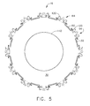
- fuel nozzle 64 is positioned within cyclone 120 in a generally radial configuration. In a radial configuration, fuel nozzle 64 may be positioned along axis of symmetry 62, as shown in Figure 5. As shown in Figure 5, fuel nozzle 64 is inserted into cyclone 120 in a substantially radial orientation. Air flows through dome assembly 50 and inlet end 34 into chamber 30 in a radial direction, and exits chamber 30 at outlet end 38 in an axial direction.
- fuel nozzle 64 may be positioned in a generally radial configuration and including a circumferential component, such as shown in Figure 6.
- a circumferential component such as shown in Figure 6.
- fuel nozzle 64 positioned in a generally radial configuration having a circumferential component at least a portion of fuel nozzle 64 is positioned within combustion chamber 30 and directed at an inner combustor liner 140 at an indirect angle of incidence.
- a greater distance between nozzle tip 68 (not shown in Figure 6) and inner liner 140 and the indirect angle of incidence facilitates an improvement in inner liner durability.
- a bulk swirl is added to combustor 16 and an effective burner length is increased, which facilitates an improvement in emissions and an improved profile/pattern factor.
- a fuel conduit 130 conveys fuel from fuel nozzle valve discharge ports (not shown), or directly from fuel nozzle inlet fittings, if valves are not used, to combustor 16 via pilot and main injectors and includes a pilot fuel circuit (not shown) and a main fuel circuit (not shown).
- the pilot fuel circuit supplies fuel to pilot fuel injector 66 and the main fuel circuit supplies fuel to main mixer 56 and includes a plurality of independent fuel stages used to control nitrous oxide emissions generated within combustor 16.
- the fuel conduit provides high thermal conductivity between the pilot and main circuits to allow one to cool the other for different pilot/main flow splits to minimize fuel thermal deposits (coking).
- the main circuit fuel-wetted wall geometries are aerodynamically smooth, contoured, and devoid of stagnant pockets or flow separation, such that when main fuel flow is shut off by upstream valves, air purge may be used to quickly and effectively remove liquid fuel from the circuit with very little residual fuel remaining.
- the main fuel circuit network and static air pressures at the injection orifice discharge points are designed to insure each leg of the circuit is effectively air purged when main flow is shut-off.
- pilot fuel circuit injects fuel to combustor 16 through pilot fuel injector 66. Simultaneously, airflow enters pilot swirlers 71 and cyclone vanes 122. The pilot airflow flows substantially parallel to center mixer axis of symmetry 62 and strikes pilot splitter 80 which directs the pilot airflow in a swirling motion towards fuel exiting pilot fuel injector 66. More specifically, the airflow is directed into the pilot flame zone downstream from pilot mixer 54 by lip 108. The pilot airflow does not collapse a spray pattern (not shown) of pilot fuel injector 66, but instead stabilizes and atomizes the fuel. Airflow discharged through main mixer 56 is channeled into combustion chamber 30 in a radial direction.
- main mixer 56 is supplied fuel with main fuel circuit 134 and injected radially outward with fuel injection ports 98.
- Cyclone vanes 122 facilitate radial and circumferential fuel-air mixing to provide a substantially uniform fuel and air distribution for combustion.
- radial penetration of fuel injected through injection ports 98 forces the radially penetrating fuel to extend circumferentially within main mixer cavity 92 to facilitate fuel-air mixing and to enable main mixer 56 to operate with a lean air-fuel mixture.
- uniformly distributing the fuel-air mixture facilitates obtaining a complete combustion to reduce high power operation NO X emissions.
- the above-described combustor configuration provides improvements to the engine system, the combustor and the fuel nozzle configuration.
- the combustor configuration of this invention provides a compact engine due to the decrease in a length of the combustor. By reducing the combustor length and, thus, the length of the engine, the weight of the engine is reduced. Further, the shortened length of the rotor shaft facilitates improvement in shaft dynamics.
- the combustor configuration of the present invention provides a longer effective burner length for a corresponding combustor length.
- a longer burner length improves the performance of the combustor.
- the radial TAPS design according to the present invention provides a burner length of about 4.34 inches, compared to a burner length of about 2.95 inches for a conventional axial TAPS design within an identical engine envelope.
- the increased burner length of the radial TAPS mixer overcomes limiting factors including, without limitation, overheating of the inner liner and poor exit temperature profile, by providing superior fuel/air mixing of a higher percentage of combustion air, without the loss of lean blow-out margin, starting performance and/or low power efficiencies.
- the present invention provides a fuel nozzle having a shorter stem connecting the flange to the fuel nozzle tip.
- the shorter stem reduces the weight of the fuel nozzle and a surface area exposed to hot gases, which will further reduce the heat transferred by the fuel. The reduced heat transfer will decrease a risk of coking within the fuel nozzle.
- a shorter stem facilitates a decrease in fuel circuit volume. Therefore, less fuel is purged on shutdown and shorter fill times are required when turning a circuit on, which improves the engine acceleration response time.
Landscapes
- Engineering & Computer Science (AREA)
- Chemical & Material Sciences (AREA)
- Combustion & Propulsion (AREA)
- Mechanical Engineering (AREA)
- General Engineering & Computer Science (AREA)
Applications Claiming Priority (1)
| Application Number | Priority Date | Filing Date | Title |
|---|---|---|---|
| US11/364,914 US7716931B2 (en) | 2006-03-01 | 2006-03-01 | Method and apparatus for assembling gas turbine engine |
Publications (1)
| Publication Number | Publication Date |
|---|---|
| EP1830129A2 true EP1830129A2 (de) | 2007-09-05 |
Family
ID=38016905
Family Applications (1)
| Application Number | Title | Priority Date | Filing Date |
|---|---|---|---|
| EP07103306A Withdrawn EP1830129A2 (de) | 2006-03-01 | 2007-03-01 | Verfahren und Vorrichtung zur Montage eines Gasturbinentriebwerks |
Country Status (4)
| Country | Link |
|---|---|
| US (1) | US7716931B2 (de) |
| EP (1) | EP1830129A2 (de) |
| JP (1) | JP5080825B2 (de) |
| CN (1) | CN101029739B (de) |
Cited By (5)
| Publication number | Priority date | Publication date | Assignee | Title |
|---|---|---|---|---|
| WO2013013740A2 (de) * | 2011-07-28 | 2013-01-31 | Rolls-Royce Deutschland Ltd & Co Kg | Gasturbinenzentripetalringbrennkammer sowie verfahren zur strömungsführung |
| US8925323B2 (en) | 2012-04-30 | 2015-01-06 | General Electric Company | Fuel/air premixing system for turbine engine |
| US9151223B2 (en) | 2010-06-15 | 2015-10-06 | Rolls-Royce Deutschland Ltd & Co Kg | Gas turbine combustion chamber arrangement of axial type of construction |
| FR3080672A1 (fr) * | 2018-04-26 | 2019-11-01 | Safran Helicopter Engines | Prechambre pour chambre de combustion annulaire a ecoulement giratoire pour moteur a turbine a gaz |
| FR3116592A1 (fr) * | 2020-11-26 | 2022-05-27 | Safran Aircraft Engines | Vrille pour dispositif d’injection étagé de turbomachine |
Families Citing this family (33)
| Publication number | Priority date | Publication date | Assignee | Title |
|---|---|---|---|---|
| US9052114B1 (en) * | 2009-04-30 | 2015-06-09 | Majed Toqan | Tangential annular combustor with premixed fuel and air for use on gas turbine engines |
| US9091446B1 (en) * | 2009-04-30 | 2015-07-28 | Majed Toqan | Tangential and flameless annular combustor for use on gas turbine engines |
| US9181812B1 (en) * | 2009-05-05 | 2015-11-10 | Majed Toqan | Can-annular combustor with premixed tangential fuel-air nozzles for use on gas turbine engines |
| US8904799B2 (en) * | 2009-05-25 | 2014-12-09 | Majed Toqan | Tangential combustor with vaneless turbine for use on gas turbine engines |
| CN102128719B (zh) * | 2010-12-13 | 2012-10-24 | 中国航空动力机械研究所 | 扇形回流燃烧室及其对开式燃烧室机匣 |
| US20120164589A1 (en) * | 2010-12-22 | 2012-06-28 | General Electric Company | Optical combustor probe system |
| US9046262B2 (en) * | 2011-06-27 | 2015-06-02 | General Electric Company | Premixer fuel nozzle for gas turbine engine |
| US8893382B2 (en) * | 2011-09-30 | 2014-11-25 | General Electric Company | Combustion system and method of assembling the same |
| US9194586B2 (en) | 2011-12-07 | 2015-11-24 | Pratt & Whitney Canada Corp. | Two-stage combustor for gas turbine engine |
| US9243802B2 (en) | 2011-12-07 | 2016-01-26 | Pratt & Whitney Canada Corp. | Two-stage combustor for gas turbine engine |
| US9416972B2 (en) * | 2011-12-07 | 2016-08-16 | Pratt & Whitney Canada Corp. | Two-stage combustor for gas turbine engine |
| US10295191B2 (en) * | 2011-12-31 | 2019-05-21 | Rolls-Royce Corporation | Gas turbine engine and annular combustor with swirler |
| JP5924618B2 (ja) * | 2012-06-07 | 2016-05-25 | 川崎重工業株式会社 | 燃料噴射装置 |
| CA2891128C (en) | 2012-11-15 | 2017-06-13 | General Electric Company | Fuel nozzle heat shield |
| WO2015053818A2 (en) | 2013-07-15 | 2015-04-16 | United Technologies Corporation | Swirler mount interface for gas turbine engine combustor |
| US10088166B2 (en) | 2013-07-15 | 2018-10-02 | United Technologies Corporation | Swirler mount interface for gas turbine engine combustor |
| EP3039344B1 (de) | 2013-08-30 | 2018-08-08 | United Technologies Corporation | Wirblerhalterungsverbindung für eine gasturbinenbrennkammer |
| US20150107256A1 (en) * | 2013-10-17 | 2015-04-23 | Pratt & Whitney Canada Corp. | Combustor for gas turbine engine |
| WO2015147951A2 (en) | 2014-01-24 | 2015-10-01 | United Technologies Corporation | Axial staged combustor with restricted main fuel injector |
| US10107498B2 (en) * | 2014-12-11 | 2018-10-23 | General Electric Company | Injection systems for fuel and gas |
| FR3035707B1 (fr) * | 2015-04-29 | 2019-11-01 | Safran Aircraft Engines | Chambre de combustion coudee d'une turbomachine |
| FR3038699B1 (fr) * | 2015-07-08 | 2022-06-24 | Snecma | Chambre de combustion coudee d'une turbomachine |
| US10801728B2 (en) | 2016-12-07 | 2020-10-13 | Raytheon Technologies Corporation | Gas turbine engine combustor main mixer with vane supported centerbody |
| US11149952B2 (en) | 2016-12-07 | 2021-10-19 | Raytheon Technologies Corporation | Main mixer in an axial staged combustor for a gas turbine engine |
| DE102017100984B4 (de) | 2017-01-19 | 2019-03-07 | Karlsruher Institut für Technologie | Gasturbinenbrennkammeranordnung |
| US10823418B2 (en) * | 2017-03-02 | 2020-11-03 | General Electric Company | Gas turbine engine combustor comprising air inlet tubes arranged around the combustor |
| US11561008B2 (en) * | 2017-08-23 | 2023-01-24 | General Electric Company | Fuel nozzle assembly for high fuel/air ratio and reduced combustion dynamics |
| PT3794283T (pt) * | 2018-05-15 | 2024-04-11 | Air Prod & Chem | Sistema e procedimento para melhoramento da estabilidade de combustão numa turbina a gás |
| CN110440289B (zh) * | 2019-07-26 | 2021-01-08 | 中国航发沈阳发动机研究所 | 一种燃气轮机燃烧室燃料空气高效混合装置 |
| CN110332598A (zh) * | 2019-08-11 | 2019-10-15 | 厦门易辰达机械有限公司 | 一种旋转火焰的燃气取暖炉 |
| KR102245798B1 (ko) * | 2019-09-17 | 2021-04-28 | 두산중공업 주식회사 | 연료 노즐 어셈블리 및 이를 포함하는 가스 터빈의 연소기 |
| CN113739207B (zh) * | 2021-09-22 | 2022-04-29 | 西北工业大学 | 一种采用气动内柱的旋转爆震燃烧室 |
| US11859819B2 (en) | 2021-10-15 | 2024-01-02 | General Electric Company | Ceramic composite combustor dome and liners |
Family Cites Families (38)
| Publication number | Priority date | Publication date | Assignee | Title |
|---|---|---|---|---|
| US2638745A (en) * | 1943-04-01 | 1953-05-19 | Power Jets Res & Dev Ltd | Gas turbine combustor having tangential air inlets for primary and secondary air |
| US4129985A (en) * | 1975-11-17 | 1978-12-19 | Kawasaki Jukogyo Kabushiki Kaisha | Combustor device of gas turbine engine |
| GB2008199A (en) * | 1977-09-03 | 1979-05-31 | Lucas Industries Ltd | Flame Tube |
| US4301657A (en) * | 1978-05-04 | 1981-11-24 | Caterpillar Tractor Co. | Gas turbine combustion chamber |
| US4339924A (en) | 1978-08-02 | 1982-07-20 | Solar Turbines Incorporated | Combustion systems |
| US4845940A (en) | 1981-02-27 | 1989-07-11 | Westinghouse Electric Corp. | Low NOx rich-lean combustor especially useful in gas turbines |
| CA1306873C (en) * | 1987-04-27 | 1992-09-01 | Jack R. Taylor | Low coke fuel injector for a gas turbine engine |
| US4912931A (en) | 1987-10-16 | 1990-04-03 | Prutech Ii | Staged low NOx gas turbine combustor |
| FR2639095B1 (fr) * | 1988-11-17 | 1990-12-21 | Snecma | Chambre de combustion de turbomachine a bols de prevaporisation montes flottants |
| US5069033A (en) * | 1989-12-21 | 1991-12-03 | Sundstrand Corporation | Radial inflow combustor |
| US5117636A (en) | 1990-02-05 | 1992-06-02 | General Electric Company | Low nox emission in gas turbine system |
| GB9023004D0 (en) * | 1990-10-23 | 1990-12-05 | Rolls Royce Plc | A gas turbine engine combustion chamber and a method of operating a gas turbine engine combustion chamber |
| CA2076102C (en) * | 1991-09-23 | 2001-12-18 | Stephen John Howell | Aero-slinger combustor |
| US5253478A (en) | 1991-12-30 | 1993-10-19 | General Electric Company | Flame holding diverging centerbody cup construction for a dry low NOx combustor |
| US5454221A (en) | 1994-03-14 | 1995-10-03 | General Electric Company | Dilution flow sleeve for reducing emissions in a gas turbine combustor |
| JP3464487B2 (ja) * | 1994-07-13 | 2003-11-10 | ボルボ エアロ コーポレイション | ガスタービンエンジン用低排気ガス燃焼器 |
| US6155056A (en) * | 1998-06-04 | 2000-12-05 | Pratt & Whitney Canada Corp. | Cooling louver for annular gas turbine engine combustion chamber |
| US6253538B1 (en) * | 1999-09-27 | 2001-07-03 | Pratt & Whitney Canada Corp. | Variable premix-lean burn combustor |
| DE60122415T2 (de) * | 2000-04-01 | 2006-12-21 | Alstom Technology Ltd. | Einspritzdüsen für flüssigen Brennstoff |
| US6427446B1 (en) | 2000-09-19 | 2002-08-06 | Power Systems Mfg., Llc | Low NOx emission combustion liner with circumferentially angled film cooling holes |
| US6381964B1 (en) * | 2000-09-29 | 2002-05-07 | General Electric Company | Multiple annular combustion chamber swirler having atomizing pilot |
| US6453660B1 (en) * | 2001-01-18 | 2002-09-24 | General Electric Company | Combustor mixer having plasma generating nozzle |
| FR2824625B1 (fr) * | 2001-05-10 | 2003-08-15 | Inst Francais Du Petrole | Dispositif et procede d'injection d'un combustible liquide dans un flux d'air pour une chambre de combustion |
| US6430932B1 (en) | 2001-07-19 | 2002-08-13 | Power Systems Mfg., Llc | Low NOx combustion liner with cooling air plenum recesses |
| US6865889B2 (en) | 2002-02-01 | 2005-03-15 | General Electric Company | Method and apparatus to decrease combustor emissions |
| US6691515B2 (en) * | 2002-03-12 | 2004-02-17 | Rolls-Royce Corporation | Dry low combustion system with means for eliminating combustion noise |
| US6772595B2 (en) | 2002-06-25 | 2004-08-10 | Power Systems Mfg., Llc | Advanced cooling configuration for a low emissions combustor venturi |
| US6844520B2 (en) | 2002-09-26 | 2005-01-18 | General Electric Company | Methods for fabricating gas turbine engine combustors |
| US6834505B2 (en) * | 2002-10-07 | 2004-12-28 | General Electric Company | Hybrid swirler |
| US7007480B2 (en) * | 2003-04-09 | 2006-03-07 | Honeywell International, Inc. | Multi-axial pivoting combustor liner in gas turbine engine |
| US6779268B1 (en) * | 2003-05-13 | 2004-08-24 | General Electric Company | Outer and inner cowl-wire wrap to one piece cowl conversion |
| US7121095B2 (en) * | 2003-08-11 | 2006-10-17 | General Electric Company | Combustor dome assembly of a gas turbine engine having improved deflector plates |
| US6976363B2 (en) * | 2003-08-11 | 2005-12-20 | General Electric Company | Combustor dome assembly of a gas turbine engine having a contoured swirler |
| US7310952B2 (en) * | 2003-10-17 | 2007-12-25 | General Electric Company | Methods and apparatus for attaching swirlers to gas turbine engine combustors |
| US7051532B2 (en) * | 2003-10-17 | 2006-05-30 | General Electric Company | Methods and apparatus for film cooling gas turbine engine combustors |
| FR2867552B1 (fr) | 2004-03-15 | 2008-07-11 | Gen Electric | Injecteur de carburant a pression regulee |
| US7509809B2 (en) * | 2005-06-10 | 2009-03-31 | Pratt & Whitney Canada Corp. | Gas turbine engine combustor with improved cooling |
| EP1924762B1 (de) * | 2005-09-13 | 2013-01-02 | Rolls-Royce Corporation, Ltd. | Turbomotorverbrennungssysteme |
-
2006
- 2006-03-01 US US11/364,914 patent/US7716931B2/en not_active Expired - Fee Related
-
2007
- 2007-02-28 JP JP2007049728A patent/JP5080825B2/ja not_active Expired - Fee Related
- 2007-03-01 CN CN2007100847003A patent/CN101029739B/zh not_active Expired - Fee Related
- 2007-03-01 EP EP07103306A patent/EP1830129A2/de not_active Withdrawn
Cited By (7)
| Publication number | Priority date | Publication date | Assignee | Title |
|---|---|---|---|---|
| US9151223B2 (en) | 2010-06-15 | 2015-10-06 | Rolls-Royce Deutschland Ltd & Co Kg | Gas turbine combustion chamber arrangement of axial type of construction |
| WO2013013740A2 (de) * | 2011-07-28 | 2013-01-31 | Rolls-Royce Deutschland Ltd & Co Kg | Gasturbinenzentripetalringbrennkammer sowie verfahren zur strömungsführung |
| WO2013013740A3 (de) * | 2011-07-28 | 2013-12-19 | Rolls-Royce Deutschland Ltd & Co Kg | Gasturbinenzentripetalringbrennkammer sowie verfahren zur strömungsführung |
| US9151501B2 (en) | 2011-07-28 | 2015-10-06 | Rolls-Royce Deutschland Ltd & Co Kg | Gas turbine centripetal annular combustion chamber and method for flow guidance |
| US8925323B2 (en) | 2012-04-30 | 2015-01-06 | General Electric Company | Fuel/air premixing system for turbine engine |
| FR3080672A1 (fr) * | 2018-04-26 | 2019-11-01 | Safran Helicopter Engines | Prechambre pour chambre de combustion annulaire a ecoulement giratoire pour moteur a turbine a gaz |
| FR3116592A1 (fr) * | 2020-11-26 | 2022-05-27 | Safran Aircraft Engines | Vrille pour dispositif d’injection étagé de turbomachine |
Also Published As
| Publication number | Publication date |
|---|---|
| US7716931B2 (en) | 2010-05-18 |
| JP5080825B2 (ja) | 2012-11-21 |
| CN101029739B (zh) | 2011-11-30 |
| JP2007232360A (ja) | 2007-09-13 |
| US20100083664A1 (en) | 2010-04-08 |
| CN101029739A (zh) | 2007-09-05 |
Similar Documents
| Publication | Publication Date | Title |
|---|---|---|
| US7716931B2 (en) | Method and apparatus for assembling gas turbine engine | |
| US6871501B2 (en) | Method and apparatus to decrease gas turbine engine combustor emissions | |
| US7565803B2 (en) | Swirler arrangement for mixer assembly of a gas turbine engine combustor having shaped passages | |
| US7762073B2 (en) | Pilot mixer for mixer assembly of a gas turbine engine combustor having a primary fuel injector and a plurality of secondary fuel injection ports | |
| US7464553B2 (en) | Air-assisted fuel injector for mixer assembly of a gas turbine engine combustor | |
| US7878000B2 (en) | Pilot fuel injector for mixer assembly of a high pressure gas turbine engine | |
| EP1262718B1 (de) | Methode und Anlage zur Reduzierung der Schadstoffausstosses der Brennkammer | |
| EP1672282B1 (de) | Verfahren und Vorrichtung zum Verringern von Verbrennungsschwingungen | |
| US20100251719A1 (en) | Centerbody for mixer assembly of a gas turbine engine combustor | |
| US7059135B2 (en) | Method to decrease combustor emissions | |
| US20070028618A1 (en) | Mixer assembly for combustor of a gas turbine engine having a main mixer with improved fuel penetration | |
| US4463568A (en) | Fuel injector for gas turbine engines | |
| JP2010249504A (ja) | デュアルオリフィスパイロット燃料噴射装置 | |
| US6571559B1 (en) | Anti-carboning fuel-air mixer for a gas turbine engine combustor | |
| US6862889B2 (en) | Method and apparatus to decrease combustor emissions | |
| EP3425281B1 (de) | Pilotdüse mit inline-vormischung | |
| CN115854386A (zh) | 浮动初级轮叶旋流器 | |
| US20240263786A1 (en) | Central air passage with radial fuel distributor | |
| US20240263791A1 (en) | Hydrogen fuel distributor | |
| US20230213194A1 (en) | Turbine engine fuel premixer | |
| CA2596789C (en) | Pilot mixer for mixer assembly of a gas turbine engine combustor having a primary fuel injector and a plurality of secondary fuel injection ports |
Legal Events
| Date | Code | Title | Description |
|---|---|---|---|
| PUAI | Public reference made under article 153(3) epc to a published international application that has entered the european phase |
Free format text: ORIGINAL CODE: 0009012 |
|
| AK | Designated contracting states |
Kind code of ref document: A2 Designated state(s): AT BE BG CH CY CZ DE DK EE ES FI FR GB GR HU IE IS IT LI LT LU LV MC MT NL PL PT RO SE SI SK TR |
|
| AX | Request for extension of the european patent |
Extension state: AL BA HR MK YU |
|
| STAA | Information on the status of an ep patent application or granted ep patent |
Free format text: STATUS: THE APPLICATION IS DEEMED TO BE WITHDRAWN |
|
| 18D | Application deemed to be withdrawn |
Effective date: 20111001 |