EP1829775A1 - Straddle-type vehicle - Google Patents
Straddle-type vehicle Download PDFInfo
- Publication number
- EP1829775A1 EP1829775A1 EP07004268A EP07004268A EP1829775A1 EP 1829775 A1 EP1829775 A1 EP 1829775A1 EP 07004268 A EP07004268 A EP 07004268A EP 07004268 A EP07004268 A EP 07004268A EP 1829775 A1 EP1829775 A1 EP 1829775A1
- Authority
- EP
- European Patent Office
- Prior art keywords
- cover
- face
- body frame
- straddle
- type vehicle
- Prior art date
- Legal status (The legal status is an assumption and is not a legal conclusion. Google has not performed a legal analysis and makes no representation as to the accuracy of the status listed.)
- Granted
Links
- 239000002828 fuel tank Substances 0.000 claims description 10
- 239000011347 resin Substances 0.000 claims description 5
- 229920005989 resin Polymers 0.000 claims description 5
- 230000005540 biological transmission Effects 0.000 description 4
- 239000000446 fuel Substances 0.000 description 3
- 210000002414 leg Anatomy 0.000 description 3
- 238000003466 welding Methods 0.000 description 3
- 239000000498 cooling water Substances 0.000 description 2
- 239000002184 metal Substances 0.000 description 2
- 229910052751 metal Inorganic materials 0.000 description 2
- 238000011084 recovery Methods 0.000 description 2
- XLYOFNOQVPJJNP-UHFFFAOYSA-N water Substances O XLYOFNOQVPJJNP-UHFFFAOYSA-N 0.000 description 2
- 239000003086 colorant Substances 0.000 description 1
- 230000006866 deterioration Effects 0.000 description 1
- 238000001125 extrusion Methods 0.000 description 1
- 238000007689 inspection Methods 0.000 description 1
- 210000003127 knee Anatomy 0.000 description 1
- 238000012423 maintenance Methods 0.000 description 1
- 150000002739 metals Chemical class 0.000 description 1
- 230000003014 reinforcing effect Effects 0.000 description 1
- 239000000725 suspension Substances 0.000 description 1
Images




Classifications
-
- B—PERFORMING OPERATIONS; TRANSPORTING
- B62—LAND VEHICLES FOR TRAVELLING OTHERWISE THAN ON RAILS
- B62J—CYCLE SADDLES OR SEATS; AUXILIARY DEVICES OR ACCESSORIES SPECIALLY ADAPTED TO CYCLES AND NOT OTHERWISE PROVIDED FOR, e.g. ARTICLE CARRIERS OR CYCLE PROTECTORS
- B62J17/00—Weather guards for riders; Fairings or stream-lining parts not otherwise provided for
-
- B—PERFORMING OPERATIONS; TRANSPORTING
- B62—LAND VEHICLES FOR TRAVELLING OTHERWISE THAN ON RAILS
- B62J—CYCLE SADDLES OR SEATS; AUXILIARY DEVICES OR ACCESSORIES SPECIALLY ADAPTED TO CYCLES AND NOT OTHERWISE PROVIDED FOR, e.g. ARTICLE CARRIERS OR CYCLE PROTECTORS
- B62J23/00—Other protectors specially adapted for cycles
Definitions
- the present invention relates to a straddle-type vehicle, in particular to a motorcycle which possesses a body cover being disposed so as to cover left/right sides of a vehicle.
- the present invention is one having been made in view of the above conventional circumstance, and its object is to provide a motorcycle capable of obtaining the external appearance rich in change while suppressing an increase in weight and a rise in cost.
- a straddle-type vehicle in particular motorcycle, comprising a body frame, and a body cover covering a side of the vehicle, wherein the body cover comprises a first cover with downside and upside continuous cover parts, forming a first face of the body cover, and a stepped-down cover part forming a second face of the body cover, placed more inside in the vehicle width direction than the first face.
- a first edge part of the upside continuous cover part is formed such that the first face adjoins the body frame.
- a first edge part of the downside continuous cover part is formed such that the first face adjoins a rear arm bracket.
- an edge part of the stepped-down cover part is formed such that the second face adjoins the body frame, and the first face.
- the first cover has the first face, which adjoins the body frame, has a width finer than a width of a portion to which there adjoins the body cover in the body frame, and extends in a direction having an angle with respect to a direction along which the body frame extends.
- first face and the second face in the first cover have different outer surfaces.
- the first cover comprises a bent part having been bending-formed in the vehicle width direction inside in an edge part in a side opposite to an edge adjoining the second face among edges that the first face has.
- the bent part is attached to the second cover.
- its portion separating from the body frame enters the vehicle width direction inside of a third cover having been disposed in a vehicle width direction outside.
- the first cover comprises the plural first faces, and the second face is disposed between the first faces.
- the first faces are mutually connected in a position being separated from the body frame, and a portion being surrounded by the plural first faces having been mutually connected and the body frame becomes the second face.
- the vehicle component is a seat, and the seat is made so as to be attachable/detachable without using a tool.
- the seat is detachably supported by the body frame, and possesses a lock mechanism performing a lock and an unlock by a key operation.
- the body frame comprises one pair of left/right tank rails having been disposed below a fuel tank, and the first cover adjoins the tank rails.
- the frame member is a rear part frame extending from a portion to which there adjoins the first cover of the body frame to a vehicle rearward, thereby supporting the seat.
- the first cover is made of a resin.
- Fig. 1 to Fig. 11 are views for explaining a motorcycle according to one embodiment of the present teaching.
- front/rear and left/right which are mentioned in the present embodiment, mean those having been seen under a state that a person has seated on a seat.
- 1 denotes a body frame of the motorcycle, and the body frame 1 possesses a head pipe 2 placed in a front end of the body frame, left/right tank rails 3, 3 extending slantingly downward from the head pipe 2 to a vehicle rearward, left/right rear arm brackets 4, 4 extending downward while continuing to rear ends of the left/right tank rails 3, 3, left/right seat rails 5, 5 extending slantingly upward from the left/right tank rails 3, 3 to the vehicle rearward, and left/right seat stays 6, 6 being connected to the rear parts of the left/right seat rails 5, 5 and the left/right rear arm brackets 4, 4 while being bridged.
- the left/right tank rails 3, 3 and the left/right rear arm brackets 4, 4 are ones having been formed by an extrusion forming or a welding of plural sheet metals. Further, the left/right seat rails 5, 5 and the left/right seat stays 6, 6 are ones having been formed by a metal pipe. The left/right seat stays 6, 6 are connected by welding to the rear arm brackets 4, 4 through metal-sheet-made attachment flanges 6a, 6a having been fixed to front end parts.
- a front fork 7 is supported so as to be capable of being steered left and right.
- a front wheel 8 is shaft-supported and, to its upper end, a steering handle 9 is attached.
- a front fender 14 covering an upper edge of the front wheel 8 is attached to the front fork 7.
- a headlight 15 is disposed in a front side of the head pipe 2 of the front fork 7, and a meter device 16 having a speed meter and the like is disposed above the headlight 15.
- a front end part of a rear arm 10 is supported so as to be capable of swinging up and down through a pivot shaft 10a.
- a rear wheel 11 is shaft-supported and, between the rear arm 10 and the rear arm bracket 4, a rear suspension (not shown in the drawing) is disposed.
- a fuel tank 12 is mounted on the left/right tank rails 3, 3, and a seat 13 for two riders is mounted on the left/right seat rails 5, 5 in a rear side of the fuel tank 12.
- a grab bar 50 In a rear edge part of the seat 13, there is disposed a grab bar 50 that a rear seat rider grasps.
- a water-cooled four-stroke engine 20 is mounted below the left/right tank rails 3, 3.
- the engine 20 is one of a structure in which a cylinder block 23, a cylinder head 24 and a head cover 25 have been stacked and bolt-fastening-connected to a crank case 22 in which a crank shaft 21 being laterally disposed in a vehicle width direction has been accommodated.
- a transmission case 22a incorporating in a transmission (not shown in the drawing) is monolithically formed in a rear side of the crank case 22. There is adapted such that an output shaft 26 taking out an engine rotation through the transmission is disposed in the transmission case 22a, and the rear wheel 11 is rotation-driven by the output shaft 26 through a chain 26a.
- An exhaust pipe 27 is connected to a front wall of the cylinder head 24, and the exhaust pipe 27 is connected to a muffler 28 having been disposed in a right side of the rear wheel 11 while passing below the engine 20.
- An intake pipe 29 is connected to a rear wall of the cylinder head 24, and the intake pipe 29 extends rearward between the left/right tank rails 3, 3 and is connected to an air cleaner (not shown in the drawing). Further, in a forward upper part of the engine 20, there is disposed a radiator 30 for holding an engine cooling water to a predetermined temperature.
- the seat 13 is one in which a front part seat 13a on which a driver seats and a rear part seat 13b on which a rear seat rider seats have been monolithically formed. A front end part of the seat 13 is detachably engagement-supported to the fuel tank. Further, a rear end part of the seat 13 is locked through a lock mechanism (not shown in the drawing) having been disposed between the left/right seat rails 5, 5. The lock mechanism becomes capable of being unlocked by key-operating a key cylinder 45 being disposed in a rear fender part 39b mentioned later. By unlocking by this key operation, the seat 13 can be detached upward.
- Front end parts of the left/right tank rails 3, 3 and an outside of the radiator 30 are covered by resin-made front covers 40, 40.
- the left/right front covers 40, 40 function as an air scoop introducing a travelling wind to the radiator 30.
- left/right side covers 38, 38 outsides of the left/right seat rails 5, 5 and the seat stays 6, 6 are covered by resin-made left/right side covers 38, 38.
- the left/right side cover 38 is divided into a front-side side cover (first cover) 41 and a rear-side side cover (third cover) 42.
- This rear fender 39 In lower faces of the left/right side covers 38, 38, there is disposed a rear fender 39 covering an upward of the rear wheel 11.
- This rear fender 39 has a front fender part (second cover) 39a covering a downside of the left/right seat stay 6 over a front/rear direction approximate whole length of this, and a rear fender part 39b downwardly extending slantingly rearward from a rear end of the front fender part 39a.
- the left/right rear-side side covers 42, 42 extend so as to cover between a left/right lower edge 13c of the seat 13 and the seat stay 6 and form a streamline shape in a vehicle front/rear direction. Further, a tail light 43 is mounted to a rear end opening of the left/right rear-side side covers 42, 42.
- Tandem footrests 55, 55 supporting feet of the rear seat rider are attached to front parts of the left/right seat stays 6, 6.
- the left/right tandem footrests 55 are fixed to the left/right seat stays 6, 6 by welding, and each of them has two front/rear pipe-made footrest arms 55a, 55a extending rearward slantingly downward from the seat stay 6, a footrest bracket 55b having been fixed to lower ends of the footrest arms 55a, 55a, and a foot putting member 55c being supported by the footrest bracket 55b so as to be turnable between its use position and its storage position.
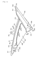
- the left/right front-side side covers 41, 41 have, when seen from a vehicle side, an approximately inverse triangle shape covering a portion being surrounded by the tank rail 3, the rear arm bracket 4, the fuel tank 12, the seat 13 and the rear-side side cover 42.
- the left front-side side cover (first cover) 41 has a first edge part being disposed so as to adjoin the body frame.
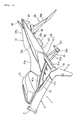
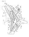
- the front-side side cover 41 has a downside continuous cover part (first face) 41a, an upside continuous cover part (first face) 41b, and a stepped-down cover part (second face) 41c.
- the downside continuous cover part (first face) 41a adjoins a rear slant face 4a of the rear arm bracket 4, extends from the rear slant face 4a in a direction having a predetermined angle with respect to a direction along which the tank rail 3 extends, concretely slantingly upward in a vehicle rear, and is disposed so as to cover an outer side of the seat stay (rear frame) 6.
- the upside continuous cover part (first face) 41b adjoins a rear slant face 3a of the tank rail 3, and extends a little slantingly downward from the rear slant face 3a while somewhat curving toward a longitudinal direction center part of the downside continuous cover part 41a.
- a most outside face 41h' of the adjacent edge part 41h is placed in an approximately the same position as an edge part 4' of the adjoining rear arm bracket 4 in a vehicle width direction.
- a most outside face 41m' of the adjacent edge part 41m is placed in approximately the same position as an edge part 3' of the adjoining tank rail 3 in the vehicle width direction.
- a most outside face 41n' of the adjacent edge part 41n has a stepped-down state so as to be placed in the vehicle width direction inside than the edge parts 3', 4' of the tank rail 3 and the rear arm bracket 4.
- the downside continuous cover part 41a has, if this is seen in section so as to be crossed, an approximately U-letter shape opening in the vehicle width direction inside.
- This downside continuous cover part 41a extends more rearward than a connection part of the upside continuous cover part 41b. More detailedly, a rear edge part 41g of the downside continuous cover part 41a enters so as to be placed in an inside of a notch part 42h of the rear-side side cover (third cover) 42.
- the downside continuous cover part 41a exhibits an external appearance like the body frame extending rearward while passing through an inside of the rear-side side cover 42.
- the downside continuous cover part 41b has, if this is seen in section so as to be crossed, the approximately U-letter shape opening in the vehicle width direction inside.
- a front end part 41i of the upside continuous cover part 41b becomes an approximately pointed shape, an intermediate part 41j is finer than the front end part 41i, and a rear end part 41k becomes widened toward the end and is connected to the downside continuous cover part 41a.
- the upside continuous cover part 41b exhibits a frame-like external appearance connecting the rear slant face 3a of the tank rail 3 and the downside continuous cover part 41a, and an external appearance supporting the fuel tank 12.
- the stepped-down cover part 41c has the stepped-down state with respect to the upside/downside continuous cover parts 41b, 41a in the vehicle width direction inside. By this, the stepped-down cover part 41c exhibits a proper external appearance of the cover covering a portion being surrounded by the upside/downside cover parts 41b, 41a and the tank rail 3.
- the upside/downside continuous cover parts 41b, 41a and the stepped-down part 41c have outer surfaces comprising different grain patterns.
- the upside/downside continuous cover parts 41b, 41a are finished to be the outer surfaces having external appearances like a frame
- the stepped-down cover part 41c is finished to be the outer surface having an external appearance like a cover, which differs from the frame.
- the upside/downside continuous cover parts 41b, 41a and the stepped-down cover part 41c may be painted in different colors. Further, a graphic may be adhered only to one, or a graphic whose external appearance differs may be adhered to each.
- the front-side side cover 41 has in its outer periphery part a bent part 41e being bending-formed in the vehicle width direction inside. By this, a rigidity of the whole front-side side cover 41 is increased.
- the downside continuous cover part 41a adjoins the adjacent edge part 41h, and has a continuous part (second edge part) 41a' extending in a direction separating rearward from the rear arm bracket 4.
- the bent part 41e in a downside of the continuous part 41a' is formed so as to be connected to the front fender part (second cover) 39a.
- the front-side side cover 41 is detachably attached to the body frame 1. By detaching the front-side side cover 41, it is possible to perform inspections and maintenances of the recovery tank, the fuel supply pipe, the power source connector, and the like.
- the front positioning protrusion 41p is detachably insertion-fixed from an outer side to an engaging hole of a positioning bracket 5e being connected to a front end part of the seat rail 5 so as to stand. Further, the rear positioning protrusion 41q is detachably insertion-fixed from the outer side to an engaging hole of an attaching flange 6a of the seat stay 6.
- a flange part 41s protruding upward from an inner edge of the bent part 41e and entering an inside of a front edge part of the rear-side side cover 42.
- an attaching part 41t extending upward so as to be concealed inside the seat 13 when seen from a side.
- the attaching part 41t is detachably fixed to an attaching bracket 5f, which has been connected so as to stand in a rear side of the positioning bracket 5e of the seat rail 5, by a bolt 59 having been mounted from the outer side.
- the attaching screw 58 is removed from an outer downside, the seat 13 is detached upward by releasing a lock mechanism, and the bolt 59 is detached from the outer side. Under this state, the front-side side cover 41 is detached by outwardly pulling out the front/rear positioning protrusions 41p, 41q.
- the downside continuous cover part 41a of the front-side side cover 41 is made a shape extending in a direction having an angle with respect to a direction along which the tank rail 3 extends, and the adjacent edge part 41h adjoining the rear arm bracket 4 of the cover part 41a is set so as to be placed in approximately the same position in the vehicle width direction as the edge part 4' of the rear arm bracket 4 to which there adjoins the most outside face 41h' of the adjacent edge part 41h.
- the adjacent edge part 41n of the stepped-down cover part 41c is stepped-down-formed so as to be biased in the vehicle width direction more inside than the edge parts 3', 4' of the tank rail 3, to which there adjoins the most outside face 41n' of the adjacent part 41n, and the rear arm bracket 4.
- the downside continuous cover part 41a exhibits a frame-like external appearance
- the stepped-down cover part 41c exhibits a proper external appearance of the cover.
- a frame design rich in change can be realized without bringing about the increase in weight and the rise in cost.
- the adjacent edge part 41m, of the upside continuous cover part 41b, adjoining the tank rail 3 has been set so as to be placed approximately the same position in the vehicle width direction as the edge part 3' of the tank rail 3 to which there adjoins the most outside face 41m' of the adjacent edge part 41m, it follows that the upside continuous cover part 41b exhibits the frame-like external appearance, so that it is possible to realize a novel frame design, which does not exist in olden times, in a low cost by the upside continuous cover part 41b and the downside continuous cover part 41a.
- the front-side side cover 41 since the front-side side cover 41 has been constituted by the downside/upside continuous cover parts 41a, 41b and the stepped-down cover part 41c placed in the vehicle width direction inside than the former, an outer surface becomes a shape having irregularities, not flat, so that the rigidity of the front-side side cover 41 becomes high.
- the front-side side cover 41 for the driver, a recognition of a riding position becomes easy. That is, although there is the fact that, at a long time ride time, also the riding position changes from a disturbance in riding posture, in a case where the front-side side cover 41 of the present embodiment is placed in an inside of legs having been performed a knee grip and the like, it is possible to grasp positions of the legs, in turn, the riding position by recognizing a changeover part (step) between the downside/upside continuous cover parts 41a, 41b and the stepped-down cover part 41c in the inside of the legs.
- the upside/downside continuous cover parts 41b, 41a and the stepped-down cover part 41c have been finished to be the outer surfaces consisting of the different grain patterns, they can be easily partitioned in a low cost into the frame-like external appearance and the proper appearance of the cover, and thus it is possible to finish more frame-likely.
- the attaching part 41t extending so as to be concealed inside the seat 13 has been formed in the front-side side cover 41, and the attaching part 41t has been fixed to the attaching bracket 5f of the seat rail 5 by the bolt 59, it is possible to prevent a deterioration of the external appearance due to the fact that the attaching part 41t is seeable and, from the fact that the attaching part 41t is exposed upward by removing the seat 13, a removal working of the front-side side cover 41 can be easily performed.
- the advantage of this embodiment is that, since the first cover adjoining the body frame has been made a constitution having the first face which has the width finer than the body frame and extends in the direction having the angle with respect to the direction along which the body frame extends, and the second face which is placed in the vehicle width direction inside than the first face and the body frame, it follows that a portion of the first face of the first cover exhibits a frame-like external appearance, and a portion of the second face exhibits a proper external appearance of the cover.
- the external appearance rich in change can be realized without bringing about the increase in weight and the rise in cost by suitably setting shapes, dimensions and the like of the first face and the second face of the first cover.
- first face and the second face in the first cover may have different outer surfaces.
- bent part may be connected to a second cover having been disposed in the vehicle width direction inside.
- the frame member is attached to a portion to which there adjoins the first cover of the body frame through an attaching flange part having been provided in the body frame, and the first cover is detachably attached to the attaching flange part.
Landscapes
- Engineering & Computer Science (AREA)
- Mechanical Engineering (AREA)
- Automatic Cycles, And Cycles In General (AREA)
- Cooling, Air Intake And Gas Exhaust, And Fuel Tank Arrangements In Propulsion Units (AREA)
- Filters For Electric Vacuum Cleaners (AREA)
- Cleaning Of Streets, Tracks, Or Beaches (AREA)
- Glass Compositions (AREA)
Abstract
Description
- The present invention relates to a straddle-type vehicle, in particular to a motorcycle which possesses a body cover being disposed so as to cover left/right sides of a vehicle.
- In the motorcycle, there is a case where an on-vehicle component having been mounted to a body frame is covered by side covers from the left/right sides. For example, in
Patent Document 1, there is adopted a structure in which between a tank rail and a fuel tank there is covered by a resin-made side cover.
Patent Document 1:JP-A-2003-11872 - By the way, in the case where, like the above conventional motorcycle, there has been made the structure in which between the tank rail and the fuel tank there is covered by the side cover, the side cover functions only as a mere exterior trim component, and an external appearance is liable to become simple one. On the other hand, there is also one in which a metal-made side cover is adopted, and there has been made so as to cause the external appearance to have a change while causing the metal-made side cover to function as a reinforcing member. However, if it is attempted to dispose the metal-made side cover, there is a problem that a weight increases and a cost rises.
- The present invention is one having been made in view of the above conventional circumstance, and its object is to provide a motorcycle capable of obtaining the external appearance rich in change while suppressing an increase in weight and a rise in cost.
- This objective is solved in an inventive manner by a straddle-type vehicle, in particular motorcycle, comprising a body frame, and a body cover covering a side of the vehicle, wherein the body cover comprises a first cover with downside and upside continuous cover parts, forming a first face of the body cover, and a stepped-down cover part forming a second face of the body cover, placed more inside in the vehicle width direction than the first face.
- Preferably, a first edge part of the upside continuous cover part is formed such that the first face adjoins the body frame.
- Further, preferably a first edge part of the downside continuous cover part is formed such that the first face adjoins a rear arm bracket.
- Still further, preferably an edge part of the stepped-down cover part is formed such that the second face adjoins the body frame, and the first face.
- According to a preferred embodiment, the first cover has the first face, which adjoins the body frame, has a width finer than a width of a portion to which there adjoins the body cover in the body frame, and extends in a direction having an angle with respect to a direction along which the body frame extends.
- Preferably, the first cover has the second face, which adjoins the body frame and the first face, and which is placed in a vehicle width direction inside than the body frame and the first face.
- Further, preferably the first face and the second face in the first cover have different outer surfaces.
- Still further, preferably the first cover comprises a bent part having been bending-formed in the vehicle width direction inside in an edge part in a side opposite to an edge adjoining the second face among edges that the first face has.
- According to another preferred embodiment, the bent part is connected to a second cover having been disposed in the vehicle width direction inside.
- Preferably, the bent part is attached to the second cover.
- Further, preferably, as to the first face, its portion separating from the body frame enters the vehicle width direction inside of a third cover having been disposed in a vehicle width direction outside.
- Still further, preferably the first cover comprises the plural first faces, and the second face is disposed between the first faces.
- Yet further still, preferably, as to the first cover, the first faces are mutually connected in a position being separated from the body frame, and a portion being surrounded by the plural first faces having been mutually connected and the body frame becomes the second face.
- Beneficially, the first cover has an attaching part having been disposed so as to be concealed inside a detachable vehicle component, and the attaching part is detachably attached to the body frame.
- According to yet another preferred embodiment, the vehicle component is a seat, and the seat is made so as to be attachable/detachable without using a tool.
- Preferably, the seat is detachably supported by the body frame, and possesses a lock mechanism performing a lock and an unlock by a key operation.
- Further, preferably, the first face covers a frame member constituting one part of the body frame.
- Still further, preferably the frame member is attached to a portion to which there adjoins the first cover of the body frame through an attaching flange part having been provided in the body frame, and the first cover is detachably attached to the attaching flange part.
- Beneficially, the body frame comprises one pair of left/right tank rails having been disposed below a fuel tank, and the first cover adjoins the tank rails.
- Preferably, the frame member is a rear part frame extending from a portion to which there adjoins the first cover of the body frame to a vehicle rearward, thereby supporting the seat.
- Further, preferably the first cover is made of a resin.
- In the following, the present invention is explained in greater detail with respect to several embodiments thereof in conjunction with the accompanying drawings, wherein:
- Fig. 1
- is a side view of a motorcycle according to one embodiment,
- Fig. 2
- is a side view of a side cover having been disposed in the motorcycle,
- Fig. 3
- is a side view of a front-side side cover of the side cover,
- Fig. 4
- is a side view of the front-side side cover,
- Fig. 5
- is a front view of the front-side side cover,
- Fig. 6
- is a sectional view (VI - VI line sectional view of Fig. 4) of the front-side side cover,
- Fig. 7
- is a sectional view (VII - VII line sectional view of Fig. 4) of a positioning part of the front-side side cover,
- Fig. 8
- is a view of the positioning part of the front-side side cover,
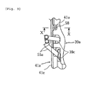
- Fig. 9
- is a bottom view of the front-side side cover,
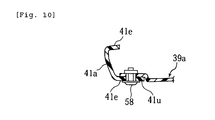
- Fig. 10
- is a sectional view (X - X line sectional view of Fig. 9) of the front-side side cover, and
- Fig. 11
- is a sectional view (XI - XI line sectional view of Fig. 3) of the front-side side cover.
-
- 3 tank rail (body frame)
- 4 rear arm bracket
- 5 seat rail
- 6 seat stay (rear part frame)
- 6a attaching flange
- 13 seat (vehicle component)
- 38 side cover (body cover)
- 39a front fender part (second cover)
- 41 front-side side cover (first cover)
- 41a downside continuous cover part (first face)
- 41b upside continuous cover part (first face)
- 41c stepped-down cover part (second face)
- 41e bent part
- 42 outside side cover (third face)
- Hereunder, an implementation mode of the present embodiment is explained on the basis of the annexed drawings.
- Fig. 1 to Fig. 11 are views for explaining a motorcycle according to one embodiment of the present teaching. Incidentally, front/rear and left/right, which are mentioned in the present embodiment, mean those having been seen under a state that a person has seated on a seat.
- In the drawings, 1 denotes a body frame of the motorcycle, and the
body frame 1 possesses ahead pipe 2 placed in a front end of the body frame, left/right tank rails 3, 3 extending slantingly downward from thehead pipe 2 to a vehicle rearward, left/rightrear arm brackets rear arm brackets - The left/right tank rails 3, 3 and the left/right
rear arm brackets rear arm brackets attachment flanges - To the
head pipe 2, afront fork 7 is supported so as to be capable of being steered left and right. In a lower end of thefront fork 7, afront wheel 8 is shaft-supported and, to its upper end, asteering handle 9 is attached. Further, afront fender 14 covering an upper edge of thefront wheel 8 is attached to thefront fork 7. - Further, a
headlight 15 is disposed in a front side of thehead pipe 2 of thefront fork 7, and ameter device 16 having a speed meter and the like is disposed above theheadlight 15. - To the left/right
rear arm brackets rear arm 10 is supported so as to be capable of swinging up and down through a pivot shaft 10a. In a rear end of therear arm 10, arear wheel 11 is shaft-supported and, between therear arm 10 and therear arm bracket 4, a rear suspension (not shown in the drawing) is disposed. - A
fuel tank 12 is mounted on the left/right tank rails 3, 3, and aseat 13 for two riders is mounted on the left/right seat rails 5, 5 in a rear side of thefuel tank 12. In a rear edge part of theseat 13, there is disposed agrab bar 50 that a rear seat rider grasps. - A water-cooled four-stroke engine 20 is mounted below the left/right tank rails 3, 3. The engine 20 is one of a structure in which a
cylinder block 23, acylinder head 24 and ahead cover 25 have been stacked and bolt-fastening-connected to a crankcase 22 in which acrank shaft 21 being laterally disposed in a vehicle width direction has been accommodated. - A
transmission case 22a incorporating in a transmission (not shown in the drawing) is monolithically formed in a rear side of thecrank case 22. There is adapted such that anoutput shaft 26 taking out an engine rotation through the transmission is disposed in thetransmission case 22a, and therear wheel 11 is rotation-driven by theoutput shaft 26 through achain 26a. - An
exhaust pipe 27 is connected to a front wall of thecylinder head 24, and theexhaust pipe 27 is connected to amuffler 28 having been disposed in a right side of therear wheel 11 while passing below the engine 20. Anintake pipe 29 is connected to a rear wall of thecylinder head 24, and theintake pipe 29 extends rearward between the left/right tank rails 3, 3 and is connected to an air cleaner (not shown in the drawing). Further, in a forward upper part of the engine 20, there is disposed aradiator 30 for holding an engine cooling water to a predetermined temperature. - The
seat 13 is one in which afront part seat 13a on which a driver seats and arear part seat 13b on which a rear seat rider seats have been monolithically formed. A front end part of theseat 13 is detachably engagement-supported to the fuel tank. Further, a rear end part of theseat 13 is locked through a lock mechanism (not shown in the drawing) having been disposed between the left/right seat rails 5, 5. The lock mechanism becomes capable of being unlocked by key-operating akey cylinder 45 being disposed in arear fender part 39b mentioned later. By unlocking by this key operation, theseat 13 can be detached upward. - Front end parts of the left/right tank rails 3, 3 and an outside of the
radiator 30 are covered by resin-made front covers 40, 40. The left/right front covers 40, 40 function as an air scoop introducing a travelling wind to theradiator 30. - Outsides of the left/right seat rails 5, 5 and the seat stays 6, 6 are covered by resin-made left/right side covers 38, 38. The left/
right side cover 38 is divided into a front-side side cover (first cover) 41 and a rear-side side cover (third cover) 42. - In lower faces of the left/right side covers 38, 38, there is disposed a
rear fender 39 covering an upward of therear wheel 11. Thisrear fender 39 has a front fender part (second cover) 39a covering a downside of the left/right seat stay 6 over a front/rear direction approximate whole length of this, and arear fender part 39b downwardly extending slantingly rearward from a rear end of thefront fender part 39a. - The left/right rear-side side covers 42, 42 extend so as to cover between a left/right
lower edge 13c of theseat 13 and theseat stay 6 and form a streamline shape in a vehicle front/rear direction. Further, atail light 43 is mounted to a rear end opening of the left/right rear-side side covers 42, 42. -
Tandem footrests right tandem footrests 55 are fixed to the left/right seat stays 6, 6 by welding, and each of them has two front/rear pipe-madefootrest arms seat stay 6, afootrest bracket 55b having been fixed to lower ends of thefootrest arms foot putting member 55c being supported by thefootrest bracket 55b so as to be turnable between its use position and its storage position. - The
footrest arms notches 39c being formed in afront fender part 39a (refer to Fig. 9). Aseat stay 6 connection portion of eachfootrest arm 55a is approximately covered by thefront fender part 39a, and prevented from being seen from an outside. - Further, to a rear side of the
tandem footrest arm 55 of theleft seat stay 6, there is attached agrip 56 grasped when using a center stand (not shown in the drawing). - The left/right front-side side covers 41, 41 have, when seen from a vehicle side, an approximately inverse triangle shape covering a portion being surrounded by the
tank rail 3, therear arm bracket 4, thefuel tank 12, theseat 13 and the rear-side side cover 42. - Within the left/right front-side side covers 41, 41, there are disposed a recovery tank (not shown in the drawing) supplying a cooling water to the
radiator 30, a fuel supply pipe supplying a fuel to the engine 20, a power source connector (not shown in the drawing), and the like. - Further, in a portion facing on a carburetor (not shown in the drawing) of the right front-
side side cover 41, there is formed an adjustingnotch 41d for adjusting an idling rotation rate (refer to Fig. 3). Incidentally, Fig. 3 shows the left front-side side cover 41, and thenotch 41d is provided only in the right front-side side cover 41. - Since the left/right front-side side covers 41 have a left/right symmetrical shape, there is detailedly explained about the left front-
side side cover 41. - The left front-side side cover (first cover) 41 has a first edge part being disposed so as to adjoin the body frame. Detailedly, the front-side side cover 41 has a downside continuous cover part (first face) 41a, an upside continuous cover part (first face) 41b, and a stepped-down cover part (second face) 41c.
- The downside continuous cover part (first face) 41a adjoins a
rear slant face 4a of therear arm bracket 4, extends from therear slant face 4a in a direction having a predetermined angle with respect to a direction along which thetank rail 3 extends, concretely slantingly upward in a vehicle rear, and is disposed so as to cover an outer side of the seat stay (rear frame) 6. - The upside continuous cover part (first face) 41b adjoins a
rear slant face 3a of thetank rail 3, and extends a little slantingly downward from therear slant face 3a while somewhat curving toward a longitudinal direction center part of the downsidecontinuous cover part 41a. - The stepped-down cover part (second face) 41c is placed in a portion being surrounded by the upside/downside
continuous cover parts tank rail 3, and forms an approximately flat face having been stepped-down-formed so as to be placed in a vehicle width direction inside than thetank rail 3 and thecover parts continuous cover parts tank rail 3. - An adjacent edge part (first edge part) 41h adjoining the
rear arm bracket 4 of the downsidecontinuous cover part 41a and an adjacent edge part (first edge part) 41m adjoining thetank rail 3 of the upsidecontinuous cover part 41b constitute one portion between the adjacent edge parts of the front-side side cover 41, and anadjacent edge part 41n of the stepped-down cover part 41c, which adjoins thetank rail 3 and therear arm bracket 4, constitutes a remaining portion of the adjacent edge part of the front-side side cover 41. - And, a most
outside face 41h' of theadjacent edge part 41h is placed in an approximately the same position as an edge part 4' of the adjoiningrear arm bracket 4 in a vehicle width direction. Further, a mostoutside face 41m' of theadjacent edge part 41m is placed in approximately the same position as an edge part 3' of the adjoiningtank rail 3 in the vehicle width direction. Additionally further, a mostoutside face 41n' of theadjacent edge part 41n has a stepped-down state so as to be placed in the vehicle width direction inside than the edge parts 3', 4' of thetank rail 3 and therear arm bracket 4. - The downside
continuous cover part 41a has, if this is seen in section so as to be crossed, an approximately U-letter shape opening in the vehicle width direction inside. This downsidecontinuous cover part 41a extends more rearward than a connection part of the upsidecontinuous cover part 41b. More detailedly, arear edge part 41g of the downsidecontinuous cover part 41a enters so as to be placed in an inside of anotch part 42h of the rear-side side cover (third cover) 42. By this, the downsidecontinuous cover part 41a exhibits an external appearance like the body frame extending rearward while passing through an inside of the rear-side side cover 42. - The downside
continuous cover part 41b has, if this is seen in section so as to be crossed, the approximately U-letter shape opening in the vehicle width direction inside. Afront end part 41i of the upsidecontinuous cover part 41b becomes an approximately pointed shape, anintermediate part 41j is finer than thefront end part 41i, and arear end part 41k becomes widened toward the end and is connected to the downsidecontinuous cover part 41a. - By this, the upside
continuous cover part 41b exhibits a frame-like external appearance connecting therear slant face 3a of thetank rail 3 and the downsidecontinuous cover part 41a, and an external appearance supporting thefuel tank 12. - The stepped-
down cover part 41c has the stepped-down state with respect to the upside/downsidecontinuous cover parts down cover part 41c exhibits a proper external appearance of the cover covering a portion being surrounded by the upside/downside cover parts tank rail 3. - The upside/downside
continuous cover parts part 41c have outer surfaces comprising different grain patterns. Detailedly, the upside/downsidecontinuous cover parts down cover part 41c is finished to be the outer surface having an external appearance like a cover, which differs from the frame. Incidentally, the upside/downsidecontinuous cover parts down cover part 41c may be painted in different colors. Further, a graphic may be adhered only to one, or a graphic whose external appearance differs may be adhered to each. - The front-side side cover 41 has in its outer periphery part a
bent part 41e being bending-formed in the vehicle width direction inside. By this, a rigidity of the whole front-side side cover 41 is increased. - The downside
continuous cover part 41a adjoins theadjacent edge part 41h, and has a continuous part (second edge part) 41a' extending in a direction separating rearward from therear arm bracket 4. Thebent part 41e in a downside of thecontinuous part 41a' is formed so as to be connected to the front fender part (second cover) 39a. By thebent parts front fender part 39a, downsides of the left/right seat stays 6, 6 are closed, thereby preventing a splashed-up water by thewear wheel 11 from entering into the front-side side cover 41. - The front-side side cover 41 is detachably attached to the
body frame 1. By detaching the front-side side cover 41, it is possible to perform inspections and maintenances of the recovery tank, the fuel supply pipe, the power source connector, and the like. - In the
front end part 41i of the upsidecontinuous cover part 41b and the front end part (adjacent edge part) 41h of the downsidecontinuous cover part 41a, there are monolithically formed front/rear positioning protrusions continuous cover part 41a, there is formed apositioning part 41r. - The
front positioning protrusion 41p is detachably insertion-fixed from an outer side to an engaging hole of apositioning bracket 5e being connected to a front end part of theseat rail 5 so as to stand. Further, therear positioning protrusion 41q is detachably insertion-fixed from the outer side to an engaging hole of an attachingflange 6a of theseat stay 6. - In a rear half part of the upside
bent part 41e of the upsidecontinuous cover part 41b, there is formed aflange part 41s protruding upward from an inner edge of thebent part 41e and entering an inside of a front edge part of the rear-side side cover 42. In a front end part of theflange part 41s, there is formed an attachingpart 41t extending upward so as to be concealed inside theseat 13 when seen from a side. - The attaching
part 41t is detachably fixed to an attachingbracket 5f, which has been connected so as to stand in a rear side of thepositioning bracket 5e of theseat rail 5, by abolt 59 having been mounted from the outer side. - In a rear end part of the downside bent
part 41e of the downsidecontinuous cover part 41a, there is formed an attachingpart 41u protruding subsequent to thebent part 41e in the vehicle width direction inside. This attachingpart 41u extends so as to overlap to a lower face of thefront fender part 39a, and is detachably fixed to thefront fender part 39a by an attachingscrew 58 being meshed from below. - In order to detach the front-
side side cover 41, the attachingscrew 58 is removed from an outer downside, theseat 13 is detached upward by releasing a lock mechanism, and thebolt 59 is detached from the outer side. Under this state, the front-side side cover 41 is detached by outwardly pulling out the front/rear positioning protrusions - According to the present embodiment, the downside
continuous cover part 41a of the front-side side cover 41 is made a shape extending in a direction having an angle with respect to a direction along which thetank rail 3 extends, and theadjacent edge part 41h adjoining therear arm bracket 4 of thecover part 41a is set so as to be placed in approximately the same position in the vehicle width direction as the edge part 4' of therear arm bracket 4 to which there adjoins the mostoutside face 41h' of theadjacent edge part 41h. And, additionally, theadjacent edge part 41n of the stepped-down cover part 41c is stepped-down-formed so as to be biased in the vehicle width direction more inside than the edge parts 3', 4' of thetank rail 3, to which there adjoins the mostoutside face 41n' of theadjacent part 41n, and therear arm bracket 4. As a result, it follows that the downsidecontinuous cover part 41a exhibits a frame-like external appearance, and the stepped-down cover part 41c exhibits a proper external appearance of the cover. Like this, by suitably setting a shape, a dimension and the like of the downsidecontinuous cover part 41a of the front-side side cover 41 made of a resin, a frame design rich in change can be realized without bringing about the increase in weight and the rise in cost. - Further, since the
adjacent edge part 41m, of the upsidecontinuous cover part 41b, adjoining thetank rail 3 has been set so as to be placed approximately the same position in the vehicle width direction as the edge part 3' of thetank rail 3 to which there adjoins the mostoutside face 41m' of theadjacent edge part 41m, it follows that the upsidecontinuous cover part 41b exhibits the frame-like external appearance, so that it is possible to realize a novel frame design, which does not exist in olden times, in a low cost by the upsidecontinuous cover part 41b and the downsidecontinuous cover part 41a. - In the present embodiment, since the front-side side cover 41 has been constituted by the downside/upside
continuous cover parts down cover part 41c placed in the vehicle width direction inside than the former, an outer surface becomes a shape having irregularities, not flat, so that the rigidity of the front-side side cover 41 becomes high. - Further, by the front-
side side cover 41, for the driver, a recognition of a riding position becomes easy. That is, although there is the fact that, at a long time ride time, also the riding position changes from a disturbance in riding posture, in a case where the front-side side cover 41 of the present embodiment is placed in an inside of legs having been performed a knee grip and the like, it is possible to grasp positions of the legs, in turn, the riding position by recognizing a changeover part (step) between the downside/upsidecontinuous cover parts down cover part 41c in the inside of the legs. - Additionally further, since the upside/downside
continuous cover parts down cover part 41c have been finished to be the outer surfaces consisting of the different grain patterns, they can be easily partitioned in a low cost into the frame-like external appearance and the proper appearance of the cover, and thus it is possible to finish more frame-likely. - In the present embodiment, in the outer periphery edge of the front-
side side cover 41, since there has been formed thebent part 41e extending while being curved in the vehicle width direction inside, it is possible to increase the rigidity of the whole front-side side cover 41, so that a deformation by an external force, and the like can be prevented. - Since the
bent part 41e has been formed in thecontinuous part 41a', of the downsidecontinuous cover part 41a, extending in the direction separating from therear arm bracket 4 while adjoining theadjacent edge part 41h, and thebent part 41e has been formed so as to be connected to thefront fender part 39a, it is possible to reliably prevent the splashed-up water by therear wheel 11 and the like from entering below theseat 13. - Further, since the attaching
part 41u has been formed in thebent part 41e, and the attachingpart 41u has been fixed to thefront fender part 39a by the attachingscrew 58 being mounted from below, a downside of the front-side side cover 41 can be attached by utilizing thefront fender part 39a, so that it is possible to make a separate component such as bracket unnecessary. - In the present embodiment, since the
continuous part 41a' of the downsidecontinuous cover part 41a is extended slantingly upward so as to be separated from therear arm bracket 4, and therear edge part 41g has been entered so as to be placed in the inside of the rear-side side cover 42, the downsidecontinuous cover part 41a can obtain such an external appearance as to extend more rearward in the rear-side side cover 42, and thus it is possible to finish more frame-likely. - Further, since the downside
continuous cover part 41a has been disposed so as to cover theseat stay 6, even in a case where theseat stay 6 may be a fine pipe in its strength, it is possible to obtain an external appearance like a strong frame. - In the present embodiment, since the attaching
part 41t extending so as to be concealed inside theseat 13 has been formed in the front-side side cover 41, and the attachingpart 41t has been fixed to the attachingbracket 5f of theseat rail 5 by thebolt 59, it is possible to prevent a deterioration of the external appearance due to the fact that the attachingpart 41t is seeable and, from the fact that the attachingpart 41t is exposed upward by removing theseat 13, a removal working of the front-side side cover 41 can be easily performed. - Further, since the
seat 13 can be removed by releasing a lock by a key operation, it is possible to more easily perform an attachment/detachment working of the front-side side cover 41. - In the present embodiment, since the
positioning protrusion 41q of the downsidecontinuous cover part 41a has been detachably attached by insertion-fixing theseat stay 6 to a hole of the attachingflange 6a connected to therear arm bracket 4, it is possible to attach the front-side side cover 41 by such a simple structure as to form only the hole of the attachingflange 6a. - Incidentally, in the above embodiment, although there has been explained a case having the down side cover
part 41a covering theseat stay 6 and the upsidecontinuous cover part 41b connecting the downsidecontinuous cover part 41a and thetank rail 3, the present teaching is not limited to this. For example, only the downsidecontinuous cover part 41a may suffice and, additionally other than the upside/downside continuous cover parts, there may be provided other continuous cover part. In this case, since the front-side side cover 41 of the present embodiment is made of the resin, the continuous cover part can be freely set. - Further, in the present embodiment, although there has been explained a case where the body frame (tank rail) is one like an angular pipe, of course the present teaching can be applied also to a motorcycle having a round pipe-like body frame.
- The description above discloses (amongst others), an embodiment of a motorcycle having possessed a body frame which is exposed to a side, has a predetermined width in its shape seen from the side, and extends in a predetermined direction, and a body cover covering a vehicle side, and characterized in that the body cover possesses a first cover having been disposed so as to adjoin the body frame, and the first cover has a first face which adjoins the body frame, has a width finer than a width of a portion to which there adjoins the body cover in the body frame, and extends in a direction having an angle with respect to a direction along which the body frame extends, and a second face which adjoins the body frame and the first face, and is placed in a vehicle width direction inside than the body frame and the first face.
- In the context of the present teaching, the "direction having the (predetermined) angle" means a "direction not parallel to the direction along which the body frame extends".
- The advantage of this embodiment is that, since the first cover adjoining the body frame has been made a constitution having the first face which has the width finer than the body frame and extends in the direction having the angle with respect to the direction along which the body frame extends, and the second face which is placed in the vehicle width direction inside than the first face and the body frame, it follows that a portion of the first face of the first cover exhibits a frame-like external appearance, and a portion of the second face exhibits a proper external appearance of the cover. By this, the external appearance rich in change can be realized without bringing about the increase in weight and the rise in cost by suitably setting shapes, dimensions and the like of the first face and the second face of the first cover.
- The description further discloses an embodiment of a motorcycle having possessed a body frame which is exposed to a side, has a predetermined width in its shape seen from the side, and extends in a predetermined direction, and a body cover covering a vehicle side, wherein the body cover possesses a first cover having been disposed so as to adjoin the body frame, and the first cover has a first face which adjoins the body frame, has a width finer than a width of a portion to which there adjoins the body cover in the body frame, and extends in a direction having an angle with respect to a direction along which the body frame extends, and a second face which adjoins the body frame and the first face, and is placed in a vehicle width direction inside than the body frame and the first face.
- Further, the first face and the second face in the first cover may have different outer surfaces.
- According to a further preferred embodiment, the first cover possesses a bent part having been bending-formed in the vehicle width direction inside in an edge part in a side opposite to an edge adjoining the second face among edges that the first face has.
- Further, the bent part may be connected to a second cover having been disposed in the vehicle width direction inside.
- Further, the bent part may be attached to the second cover.
- According to a further preferred embodiment, as to the first face, its portion separating from the body frame enters the vehicle width direction inside of a third cover having been disposed in a vehicle width direction outside.
- Further, the first cover may possess the plural first faces, and the second face may be disposed between the first faces.
- Beneficially, as to the first cover, the first faces are mutually connected in a position having been separated from the body frame, and a portion having been surrounded by the plural first faces having been mutually connected and the body frame becomes the second face.
- Preferably, the first cover has an attaching part having been disposed so as to be concealed inside a detachable vehicle component, and the attaching part is detachably attached to the body frame.
- Further, preferably the vehicle component is a seat, and the seat is made so as to be attachable/detachable without using a tool.
- Still further, preferably, the seat is detachably supported by the body frame, and possesses a lock mechanism performing a lock and an unlock by key operation.
- According to a further preferred embodiment, the first face covers a frame member constituting one part of the body frame.
- Beneficially, the frame member is attached to a portion to which there adjoins the first cover of the body frame through an attaching flange part having been provided in the body frame, and the first cover is detachably attached to the attaching flange part.
- According to a further preferred embodiment, the body frame possesses one pair of left/right tank rails having been disposed below a fuel tank, and the first cover adjoins the tank rails.
- Beneficially, the frame member is a rear part frame extending from a portion to which there adjoins the first cover of the body frame to a vehicle rearward, thereby supporting the seat.
- According to still another preferred embodiment, the first cover is made of a resin.
- The present description further discloses, in order to provide a motorcycle, in which an external appearance rich in change is obtained while suppressing a rise in cost, a preferred embodiment which possesses a first cover (front-side side cover) 41 having first edge parts (adjacent parts) 41h, 41m, 41n having been disposed so as to adjoin a body frame (rear arm bracket) 4, one
portions first cover 41 are placed in approximately the same position in a vehicle width direction as most outside faces 4', 3' of an outer surface of thebody frame 4 to which there adjoin most outside faces 41h', 41m' of outer surfaces of the one portions, and the remainingportion 41n of the first edge parts is placed in a vehicle width direction inside than the most outside face 4' of the outer surface of thebody frame 4 to which there adjoins a mostoutside face 41n' of an outer surface of the remaining portion.
Claims (21)
- Straddle-type vehicle, in particular motorcycle, comprising a body frame (3), and a body cover (38) covering a side of the vehicle, wherein the body cover (38) comprises a first cover with downside and upside continuous cover parts (41a,41b), forming a first face of the body cover (38), and a stepped-down cover part (41c) forming a second face of the body cover, placed more inside in the vehicle width direction than the first face.
- Straddle-type vehicle according to claim 1, wherein a first edge part (41m) of the upside continuous cover part (41b) is formed such that the first face adjoins the body frame (3).
- Straddle-type vehicle according to claim 1 or 2, wherein a first edge part (41h) of the downside continuous cover part (41a) is formed such that the first face adjoins a rear arm bracket (4).
- Straddle-type vehicle according to one of the claims 1 to 3, wherein an edge part (41n) of the stepped-down cover part (41c) is formed such that the second face adjoins the body frame (3), and the first face.
- Straddle-type vehicle according to one of the claims 1 to 4, wherein the first cover has the first face, which adjoins the body frame, has a width finer than a width of a portion to which there adjoins the body cover in the body frame, and extends in a direction having an angle with respect to a direction along which the body frame extends.
- Straddle-type vehicle according to one of the claims 1 to 5, wherein the first cover has the second face, which adjoins the body frame and the first face, and which is placed in a vehicle width direction inside than the body frame and the first face.
- Straddle-type vehicle according to one of the claims 1 to 6, wherein the first face and the second face in the first cover have different outer surfaces.
- Straddle-type vehicle according to one of the claims 1 to 7, wherein the first cover comprises a bent part (41e) having been bending-formed in the vehicle width direction inside in an edge part in a side opposite to an edge adjoining the second face among edges that the first face has.
- Straddle-type vehicle according to claim 8, wherein the bent part (41e) is connected to a second cover (39a) having been disposed in the vehicle width direction inside.
- Straddle-type vehicle according to claim 9, wherein the bent part (41e) is attached to the second cover (39a).
- Straddle-type vehicle according to one of the claims 1 to 10, wherein, as to the first face, its portion separating from the body frame enters the vehicle width direction inside of a third cover (42) having been disposed in a vehicle width direction outside.
- Straddle-type vehicle according to one of the claims 1 to 11, wherein the first cover comprises the plural first faces, and the second face is disposed between the first faces.
- Straddle-type vehicle according to claim 12, wherein, as to the first cover, the first faces are mutually connected in a position being separated from the body frame, and a portion being surrounded by the plural first faces having been mutually connected and the body frame becomes the second face.
- Straddle-type vehicle according to one of the claims 1 to 13, wherein the first cover has an attaching part having been disposed so as to be concealed inside a detachable vehicle component, and the attaching part is detachably attached to the body frame.
- Straddle-type vehicle according to claim 14, wherein the vehicle component is a seat, and the seat is made so as to be attachable/detachable without using a tool.
- Straddle-type vehicle according to claim 15, wherein the seat is detachably supported by the body frame, and possesses a lock mechanism performing a lock and an unlock by a key operation.
- Straddle-type vehicle according to one of the claims 1 to 16, wherein the first face covers a frame member constituting one part of the body frame.
- Straddle-type vehicle according to claim 17, wherein the frame member is attached to a portion to which there adjoins the first cover of the body frame through an attaching flange part having been provided in the body frame, and the first cover is detachably attached to the attaching flange part.
- Straddle-type vehicle according to one of the claims 1 to 18, wherein the body frame comprises one pair of left/right tank rails having been disposed below a fuel tank, and the first cover adjoins the tank rails.
- Straddle-type vehicle according to claim 19, wherein the frame member is a rear part frame extending from a portion to which there adjoins the first cover of the body frame to a vehicle rearward, thereby supporting the seat.
- Straddle-type vehicle according to one of the claims 1 to 20, wherein the first cover is made of a resin.
Applications Claiming Priority (1)
| Application Number | Priority Date | Filing Date | Title |
|---|---|---|---|
| JP2006054658A JP2007230375A (en) | 2006-03-01 | 2006-03-01 | Motorcycle |
Publications (2)
| Publication Number | Publication Date |
|---|---|
| EP1829775A1 true EP1829775A1 (en) | 2007-09-05 |
| EP1829775B1 EP1829775B1 (en) | 2009-09-09 |
Family
ID=37963671
Family Applications (1)
| Application Number | Title | Priority Date | Filing Date |
|---|---|---|---|
| EP07004268A Not-in-force EP1829775B1 (en) | 2006-03-01 | 2007-03-01 | Straddle-type vehicle |
Country Status (8)
| Country | Link |
|---|---|
| US (1) | US7850225B2 (en) |
| EP (1) | EP1829775B1 (en) |
| JP (1) | JP2007230375A (en) |
| CN (1) | CN100480127C (en) |
| AT (1) | ATE442289T1 (en) |
| DE (1) | DE602007002312D1 (en) |
| ES (1) | ES2331756T3 (en) |
| MY (1) | MY145250A (en) |
Cited By (1)
| Publication number | Priority date | Publication date | Assignee | Title |
|---|---|---|---|---|
| EP3348463A3 (en) * | 2017-01-12 | 2018-07-25 | Yamaha Hatsudoki Kabushiki Kaisha | Straddled vehicle |
Families Citing this family (13)
| Publication number | Priority date | Publication date | Assignee | Title |
|---|---|---|---|---|
| JP5001077B2 (en) * | 2007-07-05 | 2012-08-15 | 本田技研工業株式会社 | Step holder mounting structure for motorcycles |
| WO2009084491A1 (en) | 2007-12-28 | 2009-07-09 | Yamaha Hatsudoki Kabushiki Kaisha | Two-wheeled motor vehicle |
| JP4759767B2 (en) * | 2008-12-08 | 2011-08-31 | 本田技研工業株式会社 | Vehicle lumbar support mechanism |
| CN102556231A (en) * | 2012-02-07 | 2012-07-11 | 力帆实业(集团)股份有限公司 | Mounting structure for side cover component of motorcycle |
| CA2873936C (en) * | 2012-05-28 | 2018-01-09 | Honda Motor Co., Ltd. | Tank cover structure for motorcycle |
| USD693289S1 (en) * | 2012-07-20 | 2013-11-12 | Will Fountain | Pair of motorcycle body shells |
| JP5938302B2 (en) * | 2012-08-28 | 2016-06-22 | 本田技研工業株式会社 | Lid lock structure for saddle-ride type vehicles |
| JP5782424B2 (en) * | 2012-12-13 | 2015-09-24 | 本田技研工業株式会社 | Rear structure of saddle-ride type vehicle |
| JP6106482B2 (en) * | 2013-03-22 | 2017-03-29 | 本田技研工業株式会社 | Saddle riding vehicle |
| JP6166298B2 (en) * | 2015-03-20 | 2017-07-19 | 本田技研工業株式会社 | Saddle riding |
| CN107364520A (en) * | 2017-08-15 | 2017-11-21 | 康超集团广州摩托车制造有限公司 | A kind of motorcycle rear foot rest frame |
| JP6708687B2 (en) * | 2018-03-28 | 2020-06-10 | 本田技研工業株式会社 | Motorcycle seat frame |
| USD1061348S1 (en) * | 2023-07-07 | 2025-02-11 | Xiaobing Zheng | Pair of motorcycle bumper side covers |
Citations (6)
| Publication number | Priority date | Publication date | Assignee | Title |
|---|---|---|---|---|
| US5040632A (en) * | 1987-07-06 | 1991-08-20 | Honda Giken Kogyo Kabushiki Kaisha | Motorcycle |
| JPH05319340A (en) * | 1992-05-19 | 1993-12-03 | Suzuki Motor Corp | Radiator cover for motorcycle |
| JPH06247363A (en) * | 1993-02-25 | 1994-09-06 | Suzuki Motor Corp | Motorcycle frame side cover |
| JPH0826162A (en) | 1994-07-14 | 1996-01-30 | Suzuki Motor Corp | Motorcycle frame cover |
| JP2003011872A (en) | 2001-07-02 | 2003-01-15 | Yamaha Motor Co Ltd | Motorcycle fuel tank |
| US20050279556A1 (en) * | 2004-06-18 | 2005-12-22 | Toshihiko Konno | Wheeled vehicle with covers |
Family Cites Families (2)
| Publication number | Priority date | Publication date | Assignee | Title |
|---|---|---|---|---|
| JPS6159187U (en) * | 1984-09-14 | 1986-04-21 | ||
| JPH0211266Y2 (en) * | 1984-12-26 | 1990-03-20 |
-
2006
- 2006-03-01 JP JP2006054658A patent/JP2007230375A/en not_active Withdrawn
-
2007
- 2007-02-15 MY MYPI20070225A patent/MY145250A/en unknown
- 2007-02-27 US US11/679,773 patent/US7850225B2/en not_active Expired - Fee Related
- 2007-03-01 CN CNB200710005612XA patent/CN100480127C/en not_active Expired - Fee Related
- 2007-03-01 DE DE602007002312T patent/DE602007002312D1/en active Active
- 2007-03-01 EP EP07004268A patent/EP1829775B1/en not_active Not-in-force
- 2007-03-01 ES ES07004268T patent/ES2331756T3/en active Active
- 2007-03-01 AT AT07004268T patent/ATE442289T1/en not_active IP Right Cessation
Patent Citations (6)
| Publication number | Priority date | Publication date | Assignee | Title |
|---|---|---|---|---|
| US5040632A (en) * | 1987-07-06 | 1991-08-20 | Honda Giken Kogyo Kabushiki Kaisha | Motorcycle |
| JPH05319340A (en) * | 1992-05-19 | 1993-12-03 | Suzuki Motor Corp | Radiator cover for motorcycle |
| JPH06247363A (en) * | 1993-02-25 | 1994-09-06 | Suzuki Motor Corp | Motorcycle frame side cover |
| JPH0826162A (en) | 1994-07-14 | 1996-01-30 | Suzuki Motor Corp | Motorcycle frame cover |
| JP2003011872A (en) | 2001-07-02 | 2003-01-15 | Yamaha Motor Co Ltd | Motorcycle fuel tank |
| US20050279556A1 (en) * | 2004-06-18 | 2005-12-22 | Toshihiko Konno | Wheeled vehicle with covers |
Cited By (1)
| Publication number | Priority date | Publication date | Assignee | Title |
|---|---|---|---|---|
| EP3348463A3 (en) * | 2017-01-12 | 2018-07-25 | Yamaha Hatsudoki Kabushiki Kaisha | Straddled vehicle |
Also Published As
| Publication number | Publication date |
|---|---|
| MY145250A (en) | 2012-01-13 |
| CN101028847A (en) | 2007-09-05 |
| ATE442289T1 (en) | 2009-09-15 |
| US20070205631A1 (en) | 2007-09-06 |
| EP1829775B1 (en) | 2009-09-09 |
| US7850225B2 (en) | 2010-12-14 |
| ES2331756T3 (en) | 2010-01-14 |
| CN100480127C (en) | 2009-04-22 |
| JP2007230375A (en) | 2007-09-13 |
| DE602007002312D1 (en) | 2009-10-22 |
Similar Documents
| Publication | Publication Date | Title |
|---|---|---|
| EP1829775B1 (en) | Straddle-type vehicle | |
| US4678223A (en) | Cowling device for riding type vehicles | |
| JP5988639B2 (en) | Wind guide structure for saddle-ride type vehicles | |
| JP5944228B2 (en) | Saddle riding | |
| EP1785344B1 (en) | Motorcycle | |
| CN101423079B (en) | Motorcycle | |
| CN110979530B (en) | Cover structure of saddle-riding vehicle | |
| CA2448666C (en) | Windscreen device for motorcycle | |
| JP5048433B2 (en) | Winker integrated rearview mirror for saddle riding type vehicles | |
| JP6208698B2 (en) | Storage structure of saddle-ride type vehicle | |
| CN111232116B (en) | Grab rail for saddle-type vehicle | |
| JP2007210486A (en) | Motorcycle | |
| JP5963206B2 (en) | Seat support structure for saddle-ride type vehicles | |
| JP6133912B2 (en) | Saddle riding | |
| EP2042414B1 (en) | Motorcycle comprising an air intake port structure | |
| JP5700676B2 (en) | Exterior parts for saddle riding type vehicles | |
| JP6935978B2 (en) | Saddle-type vehicle | |
| JP4501539B2 (en) | Motorcycle seat equipment | |
| JP2022157400A (en) | straddle-type vehicle | |
| JP4226254B2 (en) | Water jet propulsion boat | |
| EP2168851B1 (en) | Vehicle lamp supporting structure | |
| JPH04218478A (en) | Rear frame for motorcycle |
Legal Events
| Date | Code | Title | Description |
|---|---|---|---|
| PUAI | Public reference made under article 153(3) epc to a published international application that has entered the european phase |
Free format text: ORIGINAL CODE: 0009012 |
|
| 17P | Request for examination filed |
Effective date: 20070608 |
|
| AK | Designated contracting states |
Kind code of ref document: A1 Designated state(s): AT BE BG CH CY CZ DE DK EE ES FI FR GB GR HU IE IS IT LI LT LU LV MC MT NL PL PT RO SE SI SK TR |
|
| AX | Request for extension of the european patent |
Extension state: AL BA HR MK YU |
|
| 17Q | First examination report despatched |
Effective date: 20071012 |
|
| AKX | Designation fees paid |
Designated state(s): AT BE BG CH CY CZ DE DK EE ES FI FR GB GR HU IE IS IT LI LT LU LV MC MT NL PL PT RO SE SI SK TR |
|
| GRAP | Despatch of communication of intention to grant a patent |
Free format text: ORIGINAL CODE: EPIDOSNIGR1 |
|
| GRAS | Grant fee paid |
Free format text: ORIGINAL CODE: EPIDOSNIGR3 |
|
| GRAA | (expected) grant |
Free format text: ORIGINAL CODE: 0009210 |
|
| AK | Designated contracting states |
Kind code of ref document: B1 Designated state(s): AT BE BG CH CY CZ DE DK EE ES FI FR GB GR HU IE IS IT LI LT LU LV MC MT NL PL PT RO SE SI SK TR |
|
| REG | Reference to a national code |
Ref country code: GB Ref legal event code: FG4D |
|
| REG | Reference to a national code |
Ref country code: CH Ref legal event code: EP |
|
| REG | Reference to a national code |
Ref country code: IE Ref legal event code: FG4D |
|
| REF | Corresponds to: |
Ref document number: 602007002312 Country of ref document: DE Date of ref document: 20091022 Kind code of ref document: P |
|
| REG | Reference to a national code |
Ref country code: ES Ref legal event code: FG2A Ref document number: 2331756 Country of ref document: ES Kind code of ref document: T3 |
|
| PG25 | Lapsed in a contracting state [announced via postgrant information from national office to epo] |
Ref country code: LT Free format text: LAPSE BECAUSE OF FAILURE TO SUBMIT A TRANSLATION OF THE DESCRIPTION OR TO PAY THE FEE WITHIN THE PRESCRIBED TIME-LIMIT Effective date: 20090909 Ref country code: SE Free format text: LAPSE BECAUSE OF FAILURE TO SUBMIT A TRANSLATION OF THE DESCRIPTION OR TO PAY THE FEE WITHIN THE PRESCRIBED TIME-LIMIT Effective date: 20090909 Ref country code: FI Free format text: LAPSE BECAUSE OF FAILURE TO SUBMIT A TRANSLATION OF THE DESCRIPTION OR TO PAY THE FEE WITHIN THE PRESCRIBED TIME-LIMIT Effective date: 20090909 |
|
| NLV1 | Nl: lapsed or annulled due to failure to fulfill the requirements of art. 29p and 29m of the patents act | ||
| LTIE | Lt: invalidation of european patent or patent extension |
Effective date: 20090909 |
|
| PG25 | Lapsed in a contracting state [announced via postgrant information from national office to epo] |
Ref country code: SI Free format text: LAPSE BECAUSE OF FAILURE TO SUBMIT A TRANSLATION OF THE DESCRIPTION OR TO PAY THE FEE WITHIN THE PRESCRIBED TIME-LIMIT Effective date: 20090909 Ref country code: LV Free format text: LAPSE BECAUSE OF FAILURE TO SUBMIT A TRANSLATION OF THE DESCRIPTION OR TO PAY THE FEE WITHIN THE PRESCRIBED TIME-LIMIT Effective date: 20090909 Ref country code: NL Free format text: LAPSE BECAUSE OF FAILURE TO SUBMIT A TRANSLATION OF THE DESCRIPTION OR TO PAY THE FEE WITHIN THE PRESCRIBED TIME-LIMIT Effective date: 20090909 Ref country code: PL Free format text: LAPSE BECAUSE OF FAILURE TO SUBMIT A TRANSLATION OF THE DESCRIPTION OR TO PAY THE FEE WITHIN THE PRESCRIBED TIME-LIMIT Effective date: 20090909 |
|
| PG25 | Lapsed in a contracting state [announced via postgrant information from national office to epo] |
Ref country code: CY Free format text: LAPSE BECAUSE OF FAILURE TO SUBMIT A TRANSLATION OF THE DESCRIPTION OR TO PAY THE FEE WITHIN THE PRESCRIBED TIME-LIMIT Effective date: 20090909 |
|
| PG25 | Lapsed in a contracting state [announced via postgrant information from national office to epo] |
Ref country code: CZ Free format text: LAPSE BECAUSE OF FAILURE TO SUBMIT A TRANSLATION OF THE DESCRIPTION OR TO PAY THE FEE WITHIN THE PRESCRIBED TIME-LIMIT Effective date: 20090909 Ref country code: EE Free format text: LAPSE BECAUSE OF FAILURE TO SUBMIT A TRANSLATION OF THE DESCRIPTION OR TO PAY THE FEE WITHIN THE PRESCRIBED TIME-LIMIT Effective date: 20090909 Ref country code: RO Free format text: LAPSE BECAUSE OF FAILURE TO SUBMIT A TRANSLATION OF THE DESCRIPTION OR TO PAY THE FEE WITHIN THE PRESCRIBED TIME-LIMIT Effective date: 20090909 Ref country code: IS Free format text: LAPSE BECAUSE OF FAILURE TO SUBMIT A TRANSLATION OF THE DESCRIPTION OR TO PAY THE FEE WITHIN THE PRESCRIBED TIME-LIMIT Effective date: 20100109 Ref country code: PT Free format text: LAPSE BECAUSE OF FAILURE TO SUBMIT A TRANSLATION OF THE DESCRIPTION OR TO PAY THE FEE WITHIN THE PRESCRIBED TIME-LIMIT Effective date: 20100111 |
|
| PG25 | Lapsed in a contracting state [announced via postgrant information from national office to epo] |
Ref country code: SK Free format text: LAPSE BECAUSE OF FAILURE TO SUBMIT A TRANSLATION OF THE DESCRIPTION OR TO PAY THE FEE WITHIN THE PRESCRIBED TIME-LIMIT Effective date: 20090909 |
|
| PG25 | Lapsed in a contracting state [announced via postgrant information from national office to epo] |
Ref country code: AT Free format text: LAPSE BECAUSE OF FAILURE TO SUBMIT A TRANSLATION OF THE DESCRIPTION OR TO PAY THE FEE WITHIN THE PRESCRIBED TIME-LIMIT Effective date: 20090909 Ref country code: BE Free format text: LAPSE BECAUSE OF FAILURE TO SUBMIT A TRANSLATION OF THE DESCRIPTION OR TO PAY THE FEE WITHIN THE PRESCRIBED TIME-LIMIT Effective date: 20090909 |
|
| PLBE | No opposition filed within time limit |
Free format text: ORIGINAL CODE: 0009261 |
|
| STAA | Information on the status of an ep patent application or granted ep patent |
Free format text: STATUS: NO OPPOSITION FILED WITHIN TIME LIMIT |
|
| PG25 | Lapsed in a contracting state [announced via postgrant information from national office to epo] |
Ref country code: DK Free format text: LAPSE BECAUSE OF FAILURE TO SUBMIT A TRANSLATION OF THE DESCRIPTION OR TO PAY THE FEE WITHIN THE PRESCRIBED TIME-LIMIT Effective date: 20090909 |
|
| 26N | No opposition filed |
Effective date: 20100610 |
|
| PG25 | Lapsed in a contracting state [announced via postgrant information from national office to epo] |
Ref country code: GR Free format text: LAPSE BECAUSE OF FAILURE TO SUBMIT A TRANSLATION OF THE DESCRIPTION OR TO PAY THE FEE WITHIN THE PRESCRIBED TIME-LIMIT Effective date: 20091210 Ref country code: MC Free format text: LAPSE BECAUSE OF NON-PAYMENT OF DUE FEES Effective date: 20100331 |
|
| PG25 | Lapsed in a contracting state [announced via postgrant information from national office to epo] |
Ref country code: IE Free format text: LAPSE BECAUSE OF NON-PAYMENT OF DUE FEES Effective date: 20100301 |
|
| PG25 | Lapsed in a contracting state [announced via postgrant information from national office to epo] |
Ref country code: MT Free format text: LAPSE BECAUSE OF FAILURE TO SUBMIT A TRANSLATION OF THE DESCRIPTION OR TO PAY THE FEE WITHIN THE PRESCRIBED TIME-LIMIT Effective date: 20090909 |
|
| PGRI | Patent reinstated in contracting state [announced from national office to epo] |
Ref country code: IT Effective date: 20110501 |
|
| REG | Reference to a national code |
Ref country code: CH Ref legal event code: PL |
|
| PG25 | Lapsed in a contracting state [announced via postgrant information from national office to epo] |
Ref country code: CH Free format text: LAPSE BECAUSE OF NON-PAYMENT OF DUE FEES Effective date: 20110331 Ref country code: LI Free format text: LAPSE BECAUSE OF NON-PAYMENT OF DUE FEES Effective date: 20110331 |
|
| PG25 | Lapsed in a contracting state [announced via postgrant information from national office to epo] |
Ref country code: HU Free format text: LAPSE BECAUSE OF FAILURE TO SUBMIT A TRANSLATION OF THE DESCRIPTION OR TO PAY THE FEE WITHIN THE PRESCRIBED TIME-LIMIT Effective date: 20100310 Ref country code: BG Free format text: LAPSE BECAUSE OF FAILURE TO SUBMIT A TRANSLATION OF THE DESCRIPTION OR TO PAY THE FEE WITHIN THE PRESCRIBED TIME-LIMIT Effective date: 20090909 Ref country code: LU Free format text: LAPSE BECAUSE OF NON-PAYMENT OF DUE FEES Effective date: 20100301 |
|
| PG25 | Lapsed in a contracting state [announced via postgrant information from national office to epo] |
Ref country code: TR Free format text: LAPSE BECAUSE OF FAILURE TO SUBMIT A TRANSLATION OF THE DESCRIPTION OR TO PAY THE FEE WITHIN THE PRESCRIBED TIME-LIMIT Effective date: 20090909 |
|
| REG | Reference to a national code |
Ref country code: FR Ref legal event code: PLFP Year of fee payment: 10 |
|
| REG | Reference to a national code |
Ref country code: FR Ref legal event code: PLFP Year of fee payment: 11 |
|
| PGFP | Annual fee paid to national office [announced via postgrant information from national office to epo] |
Ref country code: DE Payment date: 20170322 Year of fee payment: 11 Ref country code: FR Payment date: 20170322 Year of fee payment: 11 |
|
| PGFP | Annual fee paid to national office [announced via postgrant information from national office to epo] |
Ref country code: GB Payment date: 20170322 Year of fee payment: 11 |
|
| PGFP | Annual fee paid to national office [announced via postgrant information from national office to epo] |
Ref country code: ES Payment date: 20170315 Year of fee payment: 11 |
|
| PGFP | Annual fee paid to national office [announced via postgrant information from national office to epo] |
Ref country code: IT Payment date: 20170323 Year of fee payment: 11 |
|
| REG | Reference to a national code |
Ref country code: DE Ref legal event code: R119 Ref document number: 602007002312 Country of ref document: DE |
|
| GBPC | Gb: european patent ceased through non-payment of renewal fee |
Effective date: 20180301 |
|
| PG25 | Lapsed in a contracting state [announced via postgrant information from national office to epo] |
Ref country code: DE Free format text: LAPSE BECAUSE OF NON-PAYMENT OF DUE FEES Effective date: 20181002 |
|
| PG25 | Lapsed in a contracting state [announced via postgrant information from national office to epo] |
Ref country code: IT Free format text: LAPSE BECAUSE OF NON-PAYMENT OF DUE FEES Effective date: 20180301 Ref country code: GB Free format text: LAPSE BECAUSE OF NON-PAYMENT OF DUE FEES Effective date: 20180301 |
|
| PG25 | Lapsed in a contracting state [announced via postgrant information from national office to epo] |
Ref country code: FR Free format text: LAPSE BECAUSE OF NON-PAYMENT OF DUE FEES Effective date: 20180331 |
|
| REG | Reference to a national code |
Ref country code: ES Ref legal event code: FD2A Effective date: 20190801 |
|
| PG25 | Lapsed in a contracting state [announced via postgrant information from national office to epo] |
Ref country code: ES Free format text: LAPSE BECAUSE OF NON-PAYMENT OF DUE FEES Effective date: 20180302 |