EP1829773A1 - Crawler belt and tread plate for the crawler belt - Google Patents
Crawler belt and tread plate for the crawler belt Download PDFInfo
- Publication number
- EP1829773A1 EP1829773A1 EP05811348A EP05811348A EP1829773A1 EP 1829773 A1 EP1829773 A1 EP 1829773A1 EP 05811348 A EP05811348 A EP 05811348A EP 05811348 A EP05811348 A EP 05811348A EP 1829773 A1 EP1829773 A1 EP 1829773A1
- Authority
- EP
- European Patent Office
- Prior art keywords
- main body
- shoe plate
- plate main
- shoe
- crawler belt
- Prior art date
- Legal status (The legal status is an assumption and is not a legal conclusion. Google has not performed a legal analysis and makes no representation as to the accuracy of the status listed.)
- Granted
Links
- 238000013016 damping Methods 0.000 claims abstract description 111
- 125000006850 spacer group Chemical group 0.000 claims description 27
- 238000005192 partition Methods 0.000 claims description 6
- 230000000149 penetrating effect Effects 0.000 claims description 5
- 230000002452 interceptive effect Effects 0.000 claims description 3
- 230000000694 effects Effects 0.000 abstract description 16
- 230000001133 acceleration Effects 0.000 description 25
- 238000004458 analytical method Methods 0.000 description 22
- 230000008859 change Effects 0.000 description 16
- 229910000831 Steel Inorganic materials 0.000 description 15
- 239000010959 steel Substances 0.000 description 15
- 238000012360 testing method Methods 0.000 description 10
- 238000005259 measurement Methods 0.000 description 9
- 230000010355 oscillation Effects 0.000 description 9
- 230000009467 reduction Effects 0.000 description 9
- 238000003466 welding Methods 0.000 description 8
- 238000004519 manufacturing process Methods 0.000 description 5
- 230000004048 modification Effects 0.000 description 5
- 238000012986 modification Methods 0.000 description 5
- 238000005516 engineering process Methods 0.000 description 4
- 238000000638 solvent extraction Methods 0.000 description 4
- 238000004364 calculation method Methods 0.000 description 3
- 230000006866 deterioration Effects 0.000 description 3
- 238000000034 method Methods 0.000 description 3
- 229920002430 Fibre-reinforced plastic Polymers 0.000 description 2
- 239000011151 fibre-reinforced plastic Substances 0.000 description 2
- 230000010354 integration Effects 0.000 description 2
- 230000008569 process Effects 0.000 description 2
- 229910000838 Al alloy Inorganic materials 0.000 description 1
- 240000001973 Ficus microcarpa Species 0.000 description 1
- 238000005452 bending Methods 0.000 description 1
- 238000010276 construction Methods 0.000 description 1
- 230000002708 enhancing effect Effects 0.000 description 1
- 238000002474 experimental method Methods 0.000 description 1
- 230000035939 shock Effects 0.000 description 1
- 239000010935 stainless steel Substances 0.000 description 1
- 229910001220 stainless steel Inorganic materials 0.000 description 1
- 238000010998 test method Methods 0.000 description 1
Images















Classifications
-
- B—PERFORMING OPERATIONS; TRANSPORTING
- B62—LAND VEHICLES FOR TRAVELLING OTHERWISE THAN ON RAILS
- B62D—MOTOR VEHICLES; TRAILERS
- B62D55/00—Endless track vehicles
- B62D55/08—Endless track units; Parts thereof
- B62D55/096—Endless track units; Parts thereof with noise reducing means
-
- B—PERFORMING OPERATIONS; TRANSPORTING
- B62—LAND VEHICLES FOR TRAVELLING OTHERWISE THAN ON RAILS
- B62D—MOTOR VEHICLES; TRAILERS
- B62D55/00—Endless track vehicles
- B62D55/08—Endless track units; Parts thereof
- B62D55/18—Tracks
- B62D55/20—Tracks of articulated type, e.g. chains
-
- B—PERFORMING OPERATIONS; TRANSPORTING
- B62—LAND VEHICLES FOR TRAVELLING OTHERWISE THAN ON RAILS
- B62D—MOTOR VEHICLES; TRAILERS
- B62D55/00—Endless track vehicles
- B62D55/08—Endless track units; Parts thereof
- B62D55/18—Tracks
- B62D55/20—Tracks of articulated type, e.g. chains
- B62D55/205—Connections between track links
- B62D55/21—Links connected by transverse pivot pins
-
- B—PERFORMING OPERATIONS; TRANSPORTING
- B62—LAND VEHICLES FOR TRAVELLING OTHERWISE THAN ON RAILS
- B62D—MOTOR VEHICLES; TRAILERS
- B62D55/00—Endless track vehicles
- B62D55/08—Endless track units; Parts thereof
- B62D55/18—Tracks
- B62D55/26—Ground engaging parts or elements
- B62D55/28—Ground engaging parts or elements detachable
Definitions
- the present invention relates to a crawler belt and a shoe plate for the crawler belt.
- Some work machines such as a crawler dozer include a crawler belt wound around a driving wheel and an idle wheel.
- the crawler belt includes a plurality of track links connected to each other in a looped manner, a shoe plate connected to the track links and the like.
- the crawler belt is driven by a rotation of the driving wheel to travel around an outer circumference of the driving wheel and the idle wheel, thereby moving the work machines.
- the crawler belt collides with the driving wheel and the idle wheel and with the ground, generating collision noise (acceleration noise) or wringing noise (noise caused by natural oscillation of the shoe plate and the like).
- collision noise acceleration noise
- wringing noise noise caused by natural oscillation of the shoe plate and the like
- Patent Document 1 a plurality of general steel plates are discretely laminated by plug welding on the opposite side of a grounded side of the shoe plate.
- oscillation energy of the shoe plate generated in the collision is dissipated through friction or collisions among the general steel plates, thereby reducing the noise.
- Patent Document 1 since the plurality of general steel plates are connected to the shoe plate by plug welding, a process for welding the general steel plates is necessary in manufacturing the shoe plate. Accordingly, it is difficult to satisfy a fundamental requirement of reducing manufacturing cost. Additionally, when replacing the shoe plate due to wear and the like of the shoe plate, it is also difficult to re-use the general steel plates. Hence, new general steel plates are necessary for each replacement of the shoe plate, so that herein it is also difficult to reduce the manufacturing cost.
- An object of the invention is to provide a crawler belt that allows re-use of components and improves noise reduction effects in damping.
- a crawler belt includes: track links connected in a looped manner; and shoe plates connected to the track links.
- the crawler belt is wound around a driving wheel and an idle wheel of a traveling device.
- the shoe plates each include: a shoe plate main body formed in a plate shape that extends in a width direction orthogonal to a connecting direction of the track links, the shoe plate main body having a connecting surface on which substantially central portion the track links are connected; a damping member that includes laminated plates laminated on the connecting surface and a retainer plate provided on the laminated plates; and fastening members that fasten the shoe plate main body, the laminated plates and the retainer plate while holding the laminated plates in a mutually separatable state.
- the fastening members may be any arrangement as long as the laminated plates can be slid from each other and the oscillation energy from the shoe plate which accompanies the collision can be eliminated through the friction.
- Another arrangement may be employed in which bosses are formed in advance on the shoe plate main body. The bosses are inserted in the holes formed in the laminated plates and tip ends of the bosses are welding-connected to the retainer plate.
- the fastening member may be a screw member that includes an external thread penetrating the shoe plate main body, the laminated plates and the retainer plate and an internal thread screwed with the external thread; and the shoe plate main body, the laminated plates and the retainer plate may be provided with a through hole at a position in which the screw member penetrates, the through hole having a larger diameter than that of the external thread.
- the laminated plates and the retainer plate may each include a plate body that extends from a position near one end of the shoe plate main body in the width direction to a position near the other end, the laminated plates and the retainer plate being symmetric about a connecting position of the shoe plate main body to the track links.
- the track links and the shoe plate main body may be connected by the screw member penetrating the track links and the shoe plate main body; and a spacer may be disposed on the shoe plate main body at the connecting position by the screw member, the spacer having a thickness diameter larger than that of the damping member.
- the fastening members may be disposed on an axis line extending along a width direction end of the laminated plate and on axis lines extending so as to substantially equally partition the laminated plate in a width direction into three parts.
- the fastening members may be disposed on a substantially central portion in the connecting direction of the shoe plate main body and on a center axis line extending in the width direction of the shoe plate main body.
- the laminated plates and the retainer plate may each include plate bodies that extend from a position near an end of the shoe plate main body in the width direction to a position not interfering with the track link; and the plate bodies may be disposed on one end side and the other end side of the shoe plate main body, the plate bodies being symmetrical about a connecting position of the shoe plate main body to the track links.
- the fastening members may be disposed on an axis line extending along a width direction end of the laminated plate.
- the fastening members may be disposed on an axis line extending so as to partition the laminated plate in the width direction into two parts.
- the fastening members may be disposed on a substantially central portion in the connecting direction of the shoe plate main body and on a center axis line extending in the width direction of the shoe plate main body.
- the shoe plate according to any one of eleventh to eighteenth aspects can be implemented in combination with the first to tenth aspects and may be a part of the first to tenth aspects of the invention.
- the laminated plates of the damping member are held by the fastening members in a mutually slidable manner, the oscillation energy generated in the shoe plate can be effectively dissipated by the friction or collisions in the relative movements of the laminated plates, thereby reducing noise.
- the laminated plates are not connected by welding or the like, when the shoe plate is replaced due to wear of the shoe plate, the laminated plates can be easily removed and provided for re-use.
- the assembling of the damping member can be simplified and the mobility of the laminated plates can be freely adjusted by adjusting the fastening torque.
- the laminated plates and the retainer plate are each formed by a plate body having a length that extends from a position near one end in a width direction of the shoe plate main body to a position near the other end, the plate body being symmetric about a connecting position of the shoe plate main body to the track links; sufficient damping effects that large laminated plates can provide can be expected; and the number of fastening positions of the damping member to the shoe plate main body can be reduced, thereby simplifying the structure of the damping member.
- the spacers having a larger thickness than that of the damping member are provided on the connecting positions between the track links and the shoe plate main body, force applied on the track links is prevented from being applied on the damping member such that the laminated plates of the damping member are not restrained at the connecting positions, thereby reliably maintaining the damping effects of the laminated plates.
- the plurality of fastening members are disposed on an axis line along a width direction end of the laminated plate and on axis lines which substantially equally partitioning the width direction of the laminated plate into three parts, the damping member can be attached on the shoe plate main body by minimum fastening, thereby avoiding a reduction in the damping effects.
- the damping member is fixed by the fastening members substantially at the middle in the connecting direction of the shoe plate main body, flexibility in movement of the laminated plates of the damping member is improved, thereby further enhancing the damping effects.
- the damping member is securely fixed on the shoe plate main body while the flexibility in movement of the laminated plates is ensured, thereby realizing the crawler belt having great noise reduction effects.
- the crawler belt can be easily restored to a state in which the crawler belt has original damping effects only by exchanging the whole shoe plate on which the damping member is provided.
- the pair of track links 2 have a substantially rectangular parallelepiped shape extending in a traveling direction of the crawler belt 1 (the right - left direction in Figs. 1 and 2).
- the track links 2 are disposed so as to face each other in a width direction orthogonal to the traveling direction of the crawler belt 1 (the right - left direction in Figs. 1 and 2).
- the pair of track links 2 is connected in a bendable manner with an adjacent pair of track links 2 aligned in the traveling direction of the crawler belt 1 by a bushing and a connecting pin (both not shown). Pairs of track links 2 aligned in the traveling direction of the crawler belt 1 are thus connected to each other to form a looped track chain.
- the track link 2 has circular holes 21 in one end and the other end in a longitudinal direction of the track link 2, the circular holes 21 being open in a direction orthogonal to the traveling direction.
- Two pairs of track links 2 next to each other are connected by the bushing and the connecting pin via the circular holes 21.
- two openings 22 are formed so as to be open in the same direction as the circular holes 21, the openings 22 aligned in the traveling direction of the crawler belt 1 in parallel to each other.
- a through hole 23 (Fig. 2) is formed so as to penetrate to a lower side end of the track link 2, the through holes 23 displaced from each other in a direction orthogonal to the longitudinal direction.
- the shoe plate 3 is a member that is connected with the pair of track links 2 and engaged with ground when the work machine travels.
- the shoe plate 3 includes a shoe plate main body 31, abutting portions 32, a damping member 33 and fastening members 6.
- the shoe plate main body 31 is formed by a plate having a substantially rectangular shape in plan view in which, as compared with a length dimension in a connecting direction of the pairs of track links 2, a length dimension in a width direction orthogonal to the connecting direction is larger. Ends of the shoe plate main body 31 in the traveling direction bend upward and downward, respectively.
- the adjacent shoe plates 3 are disposed with bending portions of the shoe plate main bodies 31 overlapped.
- a lower side of the shoe plate main body 31 serves as a ground engaging surface 31A and a flat portion on an upper side of the shoe plate main body 31 serves as a connecting surface 31B for connection with the track link 2.
- a grouser 311 is formed so as to project in an out-plane direction and extend in a direction orthogonal to the traveling direction of the crawler belt 1.
- the grouser 311 is for avoiding a slip in traveling and thereby raising the traction force.
- in the connecting surface 31B of the shoe plate main body 31, four through holes 312 are formed substantially at the middle in the longitudinal width direction, the through holes 312 respectively corresponding to the through holes 23 of the pair of track links 2.
- Bolts 4 are inserted into the through holes 312 from a lower side; and nuts 5 provided on the openings 22 of the track links 2 are screwed on the bolts 4, thereby connecting the shoe plate main body 31 to the track links 2.
- connecting positions between the shoe plate main body 31 and the track links 2 are provided with spacers 32.
- the spacers 32 each have a cylindrical shape in which the bolt 4 can be inserted, the spacers 32 disposed on circumferential portions of the through holes 312 of the connecting surface 31B of the shoe plate main body 31.
- the spacers 32 are formed to have a larger height dimension in an axial direction of the cylindrical shape than a thickness dimension of the later described damping member 33.
- the damping member 33 is provided on the connecting surface 31B of the shoe plate main body 31. As shown in Fig. 3, the damping member 33 has a contour dimension substantially equal to or slightly smaller than that of the connecting surface 31B of the shoe plate main body 31.
- the damping member 33 is fixed on the shoe plate main body 31 1 by the fastening members 6 provided on intersections of a center axis CA (extending in the width direction of the shoe plate main body 31 substantially at the middle in a connecting direction of the shoe plate main bodies 31) with axis lines A1, A2 (extending in parallel to the connecting direction of the shoe plate main bodies 31 near ends of the damping member 31) and axis lines A3, A4 (extending in parallel to the connecting direction and substantially equally partitioning the damping member 31 into three parts in the width direction).
- a center axis CA extending in the width direction of the shoe plate main body 31 substantially at the middle in a connecting direction of the shoe plate main bodies 31
- axis lines A1, A2 extending in parallel to the connecting direction of the shoe plate
- the damping member 33 is provided on an upper surface of the shoe plate main body 31, namely on an opposite surface of a ground engaging surface of the shoe plate 3.
- the damping member 33 includes a plurality of laminated plates 331 and a retainer plate 332 covering an upper portion of the laminated plates 331.
- the laminated plates 331 are each formed by a general steel plate having a thickness of 0.6 mm. In the first embodiment, nine laminated plates 331 are laminated to form the damping member 33.
- the retainer plate 332 is formed by a general steel plate having a thickness of 4.5 mm, the retainer plate 332 covering an uppermost portion of the laminated plates 331. Note that such general steel plates are employed as the laminated plates 331 and the retainer plate in the first embodiment, but the arrangement is not limited thereto. Aluminum alloy, stainless steel, FRP (Fiber Reinforced Plastics) and the like can be alternatively employed.
- the fastening member 6 includes a bolt 61 and a nut 62.
- the bolt 61 penetrates the damping member 33 and the nut 62 is screwed on a tip end of the bolt 61, thereby fixing the damping member 33 on the shoe plate main body 31.
- the above described laminated plates 331 and the retainer plate 332 are provided with holes into which the bolts are inserted at positions on which the fastening members 6 are disposed, the holes having a slightly larger diameter than that of the bolt 61. Accordingly, even when fastened by the fastening members 6, the laminated plates 331 can be displaced from each other in a sliding direction on the shoe plate main body 31.
- the damping member 33 is attached on the shoe plate main body 31 by the fastening members 6, the fastening members 6 being disposed on the center axis line CA extending in the width direction substantially at the middle of sides of the shoe plate main body 31 which extend along the connecting direction of the track links 2, the fastening members 6 being symmetrically disposed about a center axis line CO set substantially at the middle of the width direction of the crawler plate main body 3.
- the damping member 33 is provided with four openings 330 corresponding to the through holes 312 formed in the connecting surface 31B of the shoe plate main body 31. The above described cylindrical spacers 32 are inserted into the openings 330.
- the plurality of laminated plates 331 are bolted in a laminated manner on the connecting surface 31B of the shoe plate main body 31, when the crawler belt 1 collides with the driving wheel, the idle wheel or the like, oscillation energy of the shoe plate main body 31 generated by a shock of the collision is converted into heat energy through friction or collisions among the plurality of laminated plates 331 to be dissipated. Accordingly, noise can be reduced.
- the shoe plate 3 can be assembled only by bolt-fastening the plurality of laminated plates 331 on the shoe plate main body 31, a related-art welding process of the plurality of laminated plates on the shoe plate main body can be omitted, thereby reducing manufacturing cost.
- the plurality of laminated plates 331 can be re-used only by removing the fastening members 6, thereby reducing operation cost.
- the shoe plate main body 31 and the plurality of laminated plates 331 are adapted to have fastening positions P1, P2, P3, P4 that are set symmetric about the center axis line CO passing a middle position in the width direction of the shoe plate main body 31, the center axis line CO extending in parallel to the traveling direction, the connecting positions P1, P2 and the connecting positions P3, P4 become incident on outer sides in the width direction of the pair of track links 2, thereby simplifying the arrangement as compared with the related art.
- the damping member 33 can be fastened with the shoe plate main body 31 only by four connecting points, thereby facilitating the attachment of the damping member 33 on the shoe plate main body 31. Further, by providing four connecting points, the strength of the shoe plate main body 31 can be appropriately maintained and deterioration of or damage on the shoe plate 3 can be avoided, thereby increasing a life of the shoe plate 3.
- the spacers 32 are interposed between the shoe plate main body 31 and the track links 2, it is possible to provide a structure in which force from the track links 2 is not applied on the damping member 33 when the damping member 33 is connected with the track links 2, thereby avoiding deterioration of or damage on the plurality of laminated plates 331 caused by the track links 2. Accordingly, the damping member 33 will not be disengaged from the shoe plate main body 31 or the fastening members 6 will not loosen so as not to press the damping member 33 at a predetermined suppress strength. Hence, noise reduction effect of the damping member 33 can be appropriately maintained.
- the damping member 33 Since the strength of the damping member 33 needs not be so high, a general and low-cost steel plate or the like can be employed, thereby reducing cost of the shoe plate 3.
- Such a structure enables the damping member 33 to have the substantially same contour dimension as that of the connecting surface 31B only by providing the openings 330 for allowing the spacers 32 to be inserted in the damping member 33.
- the damping member 33 can be disposed in the vicinity of the connecting positions between the shoe plate main body 31 and the track links 2, so that the oscillation energy in the vicinity of the connecting positions can be effectively dissipated, thereby further reducing the noise.
- the damping member 33 includes the retainer plate 332, the suppress strength by the bolt-fastening is not directly applied on the plurality of the laminated plates 331.
- the retainer plate 332 the suppress strength by the bolt-fastening can be uniformly applied on the plurality of the laminated plates 331.
- the retainer plate 332 it is possible to avoid deformation of the plurality of laminated plates 331 or deterioration in a portion of the laminated plates 331 which abuts to the bolt 6; and the oscillation energy of the shoe plate main body 31 can be effectively dissipated by the plurality of laminated plates 331, thereby appropriately reducing the noise.
- the retainer plate 332 it is also possible to avoid warpage or deformation of an uppermost laminated plate 331 of the plurality of laminated plates 331.
- the laminated plates 331 and the retainer plate 332 are each formed by a single piece plate having a dimension enough to reach both ends of the shoe plate main body 31 in the width direction; and the damping member 33 is interposed on the connecting positions between the shoe plate main body 31 and the track links 2.
- the second embodiment differs in that a pair of damping members 33A, 33A aligned in the width direction are provided at positions while avoiding the connecting positions between the shoe plate main body 31 and the track links 2. Accordingly, the second embodiment is also different from the first embodiment in fastening positions by the fastening members 6.
- the damping members 33A each have a rectangular shape in plan view; and when a crawler belt 1A is assembled, the damping members 33A are disposed on the outer sides of the track links 2 (Fig. 1 or Fig. 2) in the width direction such that ends of the damping members 33A do not interfere with the track links 2. As shown in Fig. 7, the damping members 33A, 33A are disposed line-symmetrically about the center axis line CO passing a middle position in the width direction orthogonal to the traveling direction of a shoe plate 3A. In addition, in the second embodiment, since the damping members 33A are not interposed between the track links 2 and the shoe plate main body 31, the spacers 32 described in the first embodiment are omitted.
- the track links 2 directly abut on the connecting surface 31B of the shoe plate main body 31 when the crawler belt 1A is assembled.
- the damping members 33A each include the plurality of laminated plates 331 and the retainer plate 332 similarly to the damping member 33 in the first embodiment.
- the damping members 33A are each fastened by three fastening members 7.
- the shoe plate main body 31 and the damping member 33A are fastened by the three fastening members 7 at three fastening positions P5, P6, P7 that are disposed on the center axis line CA passing a substantially middle position of ends of the shoe plate 3A, the ends extending in the connecting direction of the track links 2, and are disposed at positions equally spaced in the width direction of the damping member 33A.
- the fastening positions P5, P6, P7 are symmetric about the center axis line CO as in the first embodiment.
- the damping members 33A are disposed on the outer sides in the width direction of the track links 2 on the connecting surface 31B of the shoe plate main body 31, it is possible to easily realize, without using an extra member such as the spacers, a structure in which force from the track links 2 is not applied on the damping members 33A even when the shoe plate main body 31 is connected with the track links 2.
- the shoe plate 3A can be more easily manufactured and the manufacturing cost can be reduced.
- the spacers 32 are interposed on inserting positions of the bolts 4 that connect the track links 2 with the shoe plate main body 31 such that force is not applied on the damping member 33.
- a crawler belt 1B of the third embodiment differs in that no spacer is provided.
- the damping member 33 is disposed on the connecting positions between the shoe plate main body 31 and the track links 2; and the damping member 33 is provided with four holes 312B in which the bolts 4 are inserted to be screwed with the nuts 5, thereby connecting the shoe plate main body 31 and the track links 2.
- the holes 312B is formed to have a diameter slightly larger than that of the bolts 4 such that the laminated plates of the damping member 33 are slidable in this range even when the bolts 4 and the nuts 5 are fastened by a predetermined torque.
- Fig. 9 shows a modification of the first embodiment.
- the fastening positions between the shoe plate main body 31 and the damping member 33 in the first embodiment are not limited to the fastening positions P1, P2, P3, P4 described in the first embodiment.
- the fastening may be conducted at fastening positions on a shoe plate 3B shown in Fig. 9. Specifically as shown in Fig.
- the shoe plate main body 31 and the damping member 33 are fastened at the fastening positions P1, P2, P3, P4 and at fastening positions P1A, P2A, P3A, P4A on which the first, second, third and fourth axis lines A1, A2, A3, A4 intersect with an axis line CB that is in parallel to the center axis line CA and is disposed on one end side of the shoe plate 3B in the traveling direction.
- the fastening positions P1, P2, P3, P4, P1A, P2A, P3A, P4A are symmetric about the center axis line CO that passes a middle position in the width direction orthogonal to the traveling direction and extends in parallel to the traveling direction, as in the first embodiment.
- the fastening positions between the damping member and the shoe plate main body only need to be set symmetric about the center axis line that passes a middle position in the width direction orthogonal to the traveling direction of the shoe plate and extends in parallel to the traveling direction.
- the fastening positions are set on at least two axis lines orthogonal to the traveling direction of the shoe plate, it is possible to appropriately maintain a fastening state of the plurality of laminated plates 331 to the shoe plate main body 31 and to avoid warpage or deformation of an uppermost laminated plate 331, so that the retainer plate 332 may be omitted.
- W0 910 mm
- H0 248 mm
- the holes for fixing a connecting member were formed on the center axis CA passing at the middle of the shoe plate main body 31 in the connecting direction of the track links.
- Example 4 the spacers 32 were interposed on the connecting positions between the track links and the shoe plate main body 31 as in the first embodiment.
- the outer diameter D7 of the spacers 32 was slightly smaller than the hole diameter D4 of the laminated plates 331 and than a hole diameter D5 of the retainer plate 332 as shown in Table 1 below.
- the thickness dimension T3 of the spacers 32 was larger than the total dimension of nine laminated plates 331 each having the above-described thickness T1 (i.e.
- Examples 1 to 4 were set by changing the dimension from the ends in the width direction, the hole diameter and the like of the above-described shoe plate main body 31, laminated plates 331, retainer plate 332 and spacers 32. Table 1 shows the dimensions in Examples.
- the shoe plate main body 31, the laminated plates 331 and the retainer plate 332 were integrated by the fastening members.
- the integration was conducted with the bolts and nuts of M12 by fastening at a fastening torque of 11 kg ⁇ m.
- the integration was conducted with the bolts and nuts of M22 which is larger than that in Examples 1 and 2 by fastening at a fastening torque of 70 kg ⁇ m.
- the bolts and nuts of the shoe plate main body 31 and the track links were fastened at a torque of 0.35 kg ⁇ m and then further fastened by rotating the bolt head at 120 deg.
- Example 5 employed the same arrangement as Example 1 in which the damping members 33A were provided on the shoe plate main body 31 at the ends of the shoe plate main body 31 as shown in Fig. 14.
- the damping members 33A were disposed symmetrically about the axis line CO partitioning the width dimension W0 of the shoe plate main body 31.
- the holes having the diameter D9 for inserting the fastening members were set on the center axis CA extending in the width direction of the shoe plate main body 31 so as to be symmetric about the axis line CO.
- the thickness dimension of the laminated plates of the damping members 33A and the number of the laminated plates were the same as those in Examples 1 to 4.
- the fastening members were set apart by the same dimensions W0, W1 and W2 in the width direction of the shoe plate main body 31.
- the fastening members were also set to be offset by the dimension H2 from the axis line CA extending at the middle of the length direction of the shoe plate main body 31 such that the fastening members were on the axis line CB. Note that the offset dimension was 80 mm and the damping member 33 was fastened at four positions on one side of the damping member 33.
- Fig. 16 is a side view schematically showing an arrangement of the damping noise testing device used in the damping measurement and the noise measurement.
- the damping noise testing device 10 included: a mounting base 11; a rotary supporting portion 12 mounted on the mounting base 11 and rotatably supporting a part of the crawler belt 1 via the circular holes 21 formed on one end side in the length direction of the pair of track links 2; and a test specimen 13 colliding with the pair of track links 2 when the part of the crawler belt 1 attached on the mounting base 11 rotates due to its self weight.
- an acceleration sensor 20 manufactured by PCB Piezotronics, Inc., 303A02 was attached in advance on the ground engaging surface 31A side of the shoe plate main body 31 with the part of the crawler belt 1 according to Examples 1 to 4 and Comparisons 1 and 2 attached to the damping noise testing device 10.
- the damping measurement was conducted in which the part of the crawler belt 1 was allowed to rotate due to its self weight from a position 10 mm above the test specimen 13 toward the test specimen 13, thereby making the pair of track links 2 collide with the test specimen 13.
- An acceleration in the collision was measured by the acceleration sensor 20.
- the noise measurement was conducted at a position one meter above the shoe plate main body 31 using a noise level meter (not shown) (manufactured by LION CO., LTD., N-27) and a 1/3 octave-band analysis was conducted.
- Table 2 shows results of maximum damping acceleration measurements measured by the acceleration sensor 20 in Example 1 to Comparison 2.
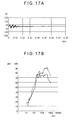
- Fig. 17A shows change in time in damping acceleration in Example 1.
- Fig. 17B shows results of the 1/3 octave-band analysis in Example 1.
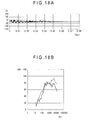
- Fig. 18A shows change in time in the damping acceleration in Example 2.
- Fig. 18B shows results of the 1/3 octave-band analysis in Example 2.
- Fig. 19A shows change in time in the damping acceleration in Example 3.
- Fig. 19B shows results of the 1/3 octave-band analysis in Example 3.
- Fig. 20A shows change in time in the damping acceleration in Example 4.
- Fig. 20B shows results in the 1/3 octave-band analysis in Example 4.
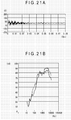
- Fig. 21A shows change in time in the damping acceleration in Example 5.
- FIG. 21B shows results in the 1/3 octave-band analysis in Example 5.
- Fig. 22A shows change in time in the damping acceleration in Example 4.
- Fig. 22B shows results in the 1/3 octave-band analysis in Example 4.
- the solid lines represent result data of Examples and the dotted lines represent 1/3 octave-band analysis data of Comparison l.
- Fig. 23A shows change in time in the damping acceleration in Comparison 1.
- Fig. 23B shows results of the 1/3 octave-band analysis in Comparison 1.
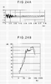
- Fig. 24A shows change in time in the damping acceleration in Comparison 2.
- Fig. 24B shows results of the 1/3 octave-band analysis in Comparison 2.
- An aspect of the invention can be applied to a crawler-belt-type traveling device used in a work machine such as a crawler dozer.
Landscapes
- Engineering & Computer Science (AREA)
- Chemical & Material Sciences (AREA)
- Combustion & Propulsion (AREA)
- Transportation (AREA)
- Mechanical Engineering (AREA)
- Vibration Dampers (AREA)
- Footwear And Its Accessory, Manufacturing Method And Apparatuses (AREA)
Abstract
Description
- The present invention relates to a crawler belt and a shoe plate for the crawler belt.
- Some work machines such as a crawler dozer include a crawler belt wound around a driving wheel and an idle wheel. The crawler belt includes a plurality of track links connected to each other in a looped manner, a shoe plate connected to the track links and the like. The crawler belt is driven by a rotation of the driving wheel to travel around an outer circumference of the driving wheel and the idle wheel, thereby moving the work machines.
When such work machines are moving, the crawler belt collides with the driving wheel and the idle wheel and with the ground, generating collision noise (acceleration noise) or wringing noise (noise caused by natural oscillation of the shoe plate and the like).
To solve the problem, a technology has been suggested (see, for example, Patent Document 1).
In the technology disclosed inPatent Document 1, a plurality of general steel plates are discretely laminated by plug welding on the opposite side of a grounded side of the shoe plate. In such an arrangement, when the crawler belt collides with the driving wheel or the idle wheel, oscillation energy of the shoe plate generated in the collision is dissipated through friction or collisions among the general steel plates, thereby reducing the noise. - [Patent Document 1]
JP-A-200-219168 - However, in the technology disclosed in
Patent Document 1, since the plurality of general steel plates are connected to the shoe plate by plug welding, a process for welding the general steel plates is necessary in manufacturing the shoe plate. Accordingly, it is difficult to satisfy a fundamental requirement of reducing manufacturing cost.
Additionally, when replacing the shoe plate due to wear and the like of the shoe plate, it is also difficult to re-use the general steel plates. Hence, new general steel plates are necessary for each replacement of the shoe plate, so that herein it is also difficult to reduce the manufacturing cost.
Further, in the technology disclosed inPatent Document 1, since the plurality of general steel plates are connected to the shoe plate by plug welding, the general steel plates are restrained to each other at the connecting portion, the friction effects which can be obtained by relative movements among the general steel plates are reduced, so that the oscillation energy cannot be effectively absorbed. - An object of the invention is to provide a crawler belt that allows re-use of components and improves noise reduction effects in damping.
- A crawler belt according to a first aspect of the invention includes: track links connected in a looped manner; and shoe plates connected to the track links. The crawler belt is wound around a driving wheel and an idle wheel of a traveling device. The shoe plates each include: a shoe plate main body formed in a plate shape that extends in a width direction orthogonal to a connecting direction of the track links, the shoe plate main body having a connecting surface on which substantially central portion the track links are connected; a damping member that includes laminated plates laminated on the connecting surface and a retainer plate provided on the laminated plates; and fastening members that fasten the shoe plate main body, the laminated plates and the retainer plate while holding the laminated plates in a mutually separatable state.
- The fastening members may be any arrangement as long as the laminated plates can be slid from each other and the oscillation energy from the shoe plate which accompanies the collision can be eliminated through the friction. For example, an arrangement in which holes are formed in advance in the laminated plates in accordance with positions of the fastening members and screw members such as bolts and nuts, riveting members such as a rivet and the like are inserted therethrough for the fastening. Another arrangement may be employed in which bosses are formed in advance on the shoe plate main body. The bosses are inserted in the holes formed in the laminated plates and tip ends of the bosses are welding-connected to the retainer plate.
- As a second aspect of the invention, in the crawler belt in the first aspect of the invention, the fastening member may be a screw member that includes an external thread penetrating the shoe plate main body, the laminated plates and the retainer plate and an internal thread screwed with the external thread; and the shoe plate main body, the laminated plates and the retainer plate may be provided with a through hole at a position in which the screw member penetrates, the through hole having a larger diameter than that of the external thread.
As a third aspect of the invention, in the crawler belt in the first or second aspect of the invention, the laminated plates and the retainer plate may each include a plate body that extends from a position near one end of the shoe plate main body in the width direction to a position near the other end, the laminated plates and the retainer plate being symmetric about a connecting position of the shoe plate main body to the track links. - As a fourth aspect of the invention, in the crawler belt according to the third aspect of the invention, the track links and the shoe plate main body may be connected by the screw member penetrating the track links and the shoe plate main body; and a spacer may be disposed on the shoe plate main body at the connecting position by the screw member, the spacer having a thickness diameter larger than that of the damping member.
As a fifth aspect of the invention, in the crawler belt according to the third or fourth aspect of the invention, the fastening members may be disposed on an axis line extending along a width direction end of the laminated plate and on axis lines extending so as to substantially equally partition the laminated plate in a width direction into three parts.
As a sixth aspect of the invention, in the crawler belt according to the fifth aspect of the invention, the fastening members may be disposed on a substantially central portion in the connecting direction of the shoe plate main body and on a center axis line extending in the width direction of the shoe plate main body. - As a seventh aspect of the invention, in the crawler belt according to the first or second aspect of the invention, the laminated plates and the retainer plate may each include plate bodies that extend from a position near an end of the shoe plate main body in the width direction to a position not interfering with the track link; and the plate bodies may be disposed on one end side and the other end side of the shoe plate main body, the plate bodies being symmetrical about a connecting position of the shoe plate main body to the track links.
As an eighth aspect of the invention, in the crawler belt according to the seventh aspect of the invention, the fastening members may be disposed on an axis line extending along a width direction end of the laminated plate. - As a ninth aspect of the invention, in the crawler belt according to the eighth aspect of the invention, the fastening members may be disposed on an axis line extending so as to partition the laminated plate in the width direction into two parts.
A tenth aspect of the invention, in the crawler belt according to any one of the seventh to ninth aspects of the invention, the fastening members may be disposed on a substantially central portion in the connecting direction of the shoe plate main body and on a center axis line extending in the width direction of the shoe plate main body. - The shoe plate according to any one of eleventh to eighteenth aspects can be implemented in combination with the first to tenth aspects and may be a part of the first to tenth aspects of the invention.
- According to the first aspect of the invention, since the laminated plates of the damping member are held by the fastening members in a mutually slidable manner, the oscillation energy generated in the shoe plate can be effectively dissipated by the friction or collisions in the relative movements of the laminated plates, thereby reducing noise. In addition, since the laminated plates are not connected by welding or the like, when the shoe plate is replaced due to wear of the shoe plate, the laminated plates can be easily removed and provided for re-use.
- According to the second aspect of the invention, since screw members are employed as the fastening members, the assembling of the damping member can be simplified and the mobility of the laminated plates can be freely adjusted by adjusting the fastening torque.
According to the third aspect of the invention, since the laminated plates and the retainer plate are each formed by a plate body having a length that extends from a position near one end in a width direction of the shoe plate main body to a position near the other end, the plate body being symmetric about a connecting position of the shoe plate main body to the track links; sufficient damping effects that large laminated plates can provide can be expected; and the number of fastening positions of the damping member to the shoe plate main body can be reduced, thereby simplifying the structure of the damping member. - According to the fourth aspect of the invention, since the spacers having a larger thickness than that of the damping member are provided on the connecting positions between the track links and the shoe plate main body, force applied on the track links is prevented from being applied on the damping member such that the laminated plates of the damping member are not restrained at the connecting positions, thereby reliably maintaining the damping effects of the laminated plates.
According to the fifth aspect of the invention, since the plurality of fastening members are disposed on an axis line along a width direction end of the laminated plate and on axis lines which substantially equally partitioning the width direction of the laminated plate into three parts, the damping member can be attached on the shoe plate main body by minimum fastening, thereby avoiding a reduction in the damping effects.
According to the sixth aspect of the invention, since the damping member is fixed by the fastening members substantially at the middle in the connecting direction of the shoe plate main body, flexibility in movement of the laminated plates of the damping member is improved, thereby further enhancing the damping effects. - According to the seventh aspect of the invention, since the laminated plates and the retainer plate are disposed so as to avoid the connecting positions of the shoe plate main body to the track links, the damping effects of the damping member are not reduced by the force applied on the track links.
According to the eighth to tenth aspects of the invention, the damping member is securely fixed on the shoe plate main body while the flexibility in movement of the laminated plates is ensured, thereby realizing the crawler belt having great noise reduction effects.
According to the eleventh to eighteenth aspects of the invention, even when the shoe plate main body needs to be replaced due to wear, the crawler belt can be easily restored to a state in which the crawler belt has original damping effects only by exchanging the whole shoe plate on which the damping member is provided. -
- Fig. 1 is a perspective view showing a structure of a crawler belt according to a first embodiment of the invention;
- Fig. 2 is an exploded perspective view showing an arrangement of the crawler belt of the first embodiment;
- Fig. 3 is a plan view showing a shoe plate of the first embodiment;
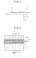
- Fig. 4 is a side view showing the shoe plate of the first embodiment;
- Fig. 5 is a cross section showing an arrangement of a damping member of the first embodiment;
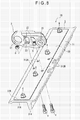
- Fig. 6 is a perspective view showing a structure of a crawler belt according to a second embodiment of the invention;
- Fig. 7 is a plan view showing a shoe plate of the second embodiment;
- Fig. 8 is an exploded perspective view showing a structure of a crawler belt according to a third embodiment of the invention;
- Fig. 9 is a plan view showing a modification according to the first embodiment;
- Fig. 10 is a plan view showing a dimension of a shoe plate main body used in examples;
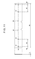
- Fig. 11 is a plan view showing a dimension of a laminated plate used in the examples;
- Fig. 12 is a plan view showing a dimension of a retainer plate used in examples;
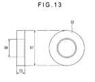
- Fig. 13 is a plan view and a side view showing a dimension of a spacer used in the examples;
- Fig. 14 is a plan view showing a dimension of a shoe plate main body and a damping member used in the examples;
- Fig. 15 is a plan view showing a dimension of a shoe plate main body and a damping member used in the examples;
- Fig. 16 is a side view schematically showing an arrangement of a damping noise testing device used in a damping measurement and a noise measurement;
- Fig. 17A is a graph showing change in time of a vibration acceleration according to a first example;
- Fig. 17B is a graph showing a result of 1/3 octave-band analysis in the first example;
- Fig. 18A is a graph showing change in time of a vibration acceleration according to a second example;
- Fig. 18B is a graph showing a result of 1/3 octave-band analysis in the second example;
- Fig. 19A is a graph showing change in time of a vibration acceleration according to a third example;
- Fig. 19B is a graph showing a result of 1/3 octave-band analysis in the third example;
- Fig. 20A is a graph showing change in time of a vibration acceleration according to a fourth example;
- Fig. 20B is a graph showing a result of 1/3 octave-band analysis in the fourth example;
- Fig. 21A is a graph showing change in time of a vibration acceleration according to a fifth example;
- Fig. 21B is a graph showing a result of 1/3 octave-band analysis in the fifth example;
- Fig. 22A is a graph showing change in time of a vibration acceleration according to a sixth example;
- Fig. 21B is a graph showing a result of 1/3 octave-band analysis in the sixth example;
- Fig. 23A is a graph showing change in time of a vibration acceleration according to a first comparison;
- Fig. 23B is a graph showing a result of 1/3 octave-band analysis in the first comparison;
- Fig. 24A is a graph showing change in time of a vibration acceleration according to a second comparison;
- Fig. 24B is a graph showing a result of 1/3 octave-band analysis in the second comparison;
- Fig. 25 is a graph showing a comparison in total noise level in frequency bands of the examples and the comparisons; and
- Fig. 26 is a graph showing a comparison in total noise level in frequency bands of the examples and the comparisons.
-
- 1: crawler belt
- 2: track link
- 3, 3A, 3B, 3C: shoe plate
- 6: fastening member
- 31: shoe plate main body
- 31B: connecting surface
- 32: abutting portion
- 33, 33A, 33B: damping member
- 330: opening
- 331: laminated plate
- 332: retainer plate
- A1, A2, A3, A4, CA, CB: axis line
- CA: center axis line
- P1, P2, P3, P4, P5, P6, P7, P1A, P2A, P3A, P4A, P5A, P6A, P7A: connecting position
- A first embodiment of the invention will be described below with reference to the drawings.
- Fig. 1 is a perspective view showing a structure of a crawler belt according to the first embodiment of the invention.
- Fig. 2 is an exploded perspective view showing an arrangement of the crawler belt.
- The pair of
track links 2 have a substantially rectangular parallelepiped shape extending in a traveling direction of the crawler belt 1 (the right - left direction in Figs. 1 and 2). The track links 2 are disposed so as to face each other in a width direction orthogonal to the traveling direction of the crawler belt 1 (the right - left direction in Figs. 1 and 2). As shown in Fig. 1, the pair oftrack links 2 is connected in a bendable manner with an adjacent pair oftrack links 2 aligned in the traveling direction of thecrawler belt 1 by a bushing and a connecting pin (both not shown). Pairs oftrack links 2 aligned in the traveling direction of thecrawler belt 1 are thus connected to each other to form a looped track chain.
As shown in Figs. 1 and 2, thetrack link 2 hascircular holes 21 in one end and the other end in a longitudinal direction of thetrack link 2, thecircular holes 21 being open in a direction orthogonal to the traveling direction. Two pairs oftrack links 2 next to each other are connected by the bushing and the connecting pin via the circular holes 21.
As shown in Figs. 1 and 2, substantially at the middle of thetrack link 2 in the longitudinal direction, twoopenings 22 are formed so as to be open in the same direction as thecircular holes 21, theopenings 22 aligned in the traveling direction of thecrawler belt 1 in parallel to each other. In each lower side surface of the openings 22 (i.e. in a surface on a connecting side with the shoe plate 3), a through hole 23 (Fig. 2) is formed so as to penetrate to a lower side end of thetrack link 2, the throughholes 23 displaced from each other in a direction orthogonal to the longitudinal direction. - The
shoe plate 3 is a member that is connected with the pair oftrack links 2 and engaged with ground when the work machine travels. As shown in Fig. 2, theshoe plate 3 includes a shoe platemain body 31, abuttingportions 32, a dampingmember 33 andfastening members 6.
As shown in Fig. 2, the shoe platemain body 31 is formed by a plate having a substantially rectangular shape in plan view in which, as compared with a length dimension in a connecting direction of the pairs oftrack links 2, a length dimension in a width direction orthogonal to the connecting direction is larger. Ends of the shoe platemain body 31 in the traveling direction bend upward and downward, respectively. When thecrawler belt 1 is assembled, theadjacent shoe plates 3 are disposed with bending portions of the shoe platemain bodies 31 overlapped.
As shown in Fig. 2, a lower side of the shoe platemain body 31 serves as aground engaging surface 31A and a flat portion on an upper side of the shoe platemain body 31 serves as a connectingsurface 31B for connection with thetrack link 2. - As shown in Fig. 2, on the
ground engaging surface 31A of the shoe platemain body 31, agrouser 311 is formed so as to project in an out-plane direction and extend in a direction orthogonal to the traveling direction of thecrawler belt 1. Thegrouser 311 is for avoiding a slip in traveling and thereby raising the traction force.
As shown in Fig. 2, in the connectingsurface 31B of the shoe platemain body 31, four throughholes 312 are formed substantially at the middle in the longitudinal width direction, the throughholes 312 respectively corresponding to the throughholes 23 of the pair oftrack links 2.Bolts 4 are inserted into the throughholes 312 from a lower side; and nuts 5 provided on theopenings 22 of thetrack links 2 are screwed on thebolts 4, thereby connecting the shoe platemain body 31 to thetrack links 2. - As shown in Fig. 2, connecting positions between the shoe plate
main body 31 and thetrack links 2 are provided withspacers 32. Thespacers 32 each have a cylindrical shape in which thebolt 4 can be inserted, thespacers 32 disposed on circumferential portions of the throughholes 312 of the connectingsurface 31B of the shoe platemain body 31. Thespacers 32 are formed to have a larger height dimension in an axial direction of the cylindrical shape than a thickness dimension of the later described dampingmember 33. When thecrawler belt 1 is assembled, thetrack links 2 only abut on thespacers 32. - The damping
member 33 is provided on the connectingsurface 31B of the shoe platemain body 31.
As shown in Fig. 3, the dampingmember 33 has a contour dimension substantially equal to or slightly smaller than that of the connectingsurface 31B of the shoe platemain body 31. The dampingmember 33 is fixed on the shoe platemain body 31 1 by thefastening members 6 provided on intersections of a center axis CA (extending in the width direction of the shoe platemain body 31 substantially at the middle in a connecting direction of the shoe plate main bodies 31) with axis lines A1, A2 (extending in parallel to the connecting direction of the shoe platemain bodies 31 near ends of the damping member 31) and axis lines A3, A4 (extending in parallel to the connecting direction and substantially equally partitioning the dampingmember 31 into three parts in the width direction).
As shown in Fig. 4, the dampingmember 33 is provided on an upper surface of the shoe platemain body 31, namely on an opposite surface of a ground engaging surface of theshoe plate 3. As shown in Fig. 5, the dampingmember 33 includes a plurality oflaminated plates 331 and aretainer plate 332 covering an upper portion of thelaminated plates 331. - The
laminated plates 331 are each formed by a general steel plate having a thickness of 0.6 mm. In the first embodiment, ninelaminated plates 331 are laminated to form the dampingmember 33.
Theretainer plate 332 is formed by a general steel plate having a thickness of 4.5 mm, theretainer plate 332 covering an uppermost portion of thelaminated plates 331. Note that such general steel plates are employed as thelaminated plates 331 and the retainer plate in the first embodiment, but the arrangement is not limited thereto. Aluminum alloy, stainless steel, FRP (Fiber Reinforced Plastics) and the like can be alternatively employed. - As shown in Fig. 5 (a cross section taken along line IV - IV in Fig. 3), the
fastening member 6 includes abolt 61 and anut 62. Thebolt 61 penetrates the dampingmember 33 and thenut 62 is screwed on a tip end of thebolt 61, thereby fixing the dampingmember 33 on the shoe platemain body 31.
Although omitted in Figs. 3 and 4, the above describedlaminated plates 331 and theretainer plate 332 are provided with holes into which the bolts are inserted at positions on which thefastening members 6 are disposed, the holes having a slightly larger diameter than that of thebolt 61. Accordingly, even when fastened by thefastening members 6, thelaminated plates 331 can be displaced from each other in a sliding direction on the shoe platemain body 31. - As shown in Fig. 3, the damping
member 33 is attached on the shoe platemain body 31 by thefastening members 6, thefastening members 6 being disposed on the center axis line CA extending in the width direction substantially at the middle of sides of the shoe platemain body 31 which extend along the connecting direction of thetrack links 2, thefastening members 6 being symmetrically disposed about a center axis line CO set substantially at the middle of the width direction of the crawler platemain body 3.
As shown in Figs. 2 and 3, the dampingmember 33 is provided with fouropenings 330 corresponding to the throughholes 312 formed in the connectingsurface 31B of the shoe platemain body 31. The above describedcylindrical spacers 32 are inserted into theopenings 330. - As stated above, in the first embodiment, since the plurality of
laminated plates 331 are bolted in a laminated manner on the connectingsurface 31B of the shoe platemain body 31, when thecrawler belt 1 collides with the driving wheel, the idle wheel or the like, oscillation energy of the shoe platemain body 31 generated by a shock of the collision is converted into heat energy through friction or collisions among the plurality oflaminated plates 331 to be dissipated. Accordingly, noise can be reduced.
Since theshoe plate 3 can be assembled only by bolt-fastening the plurality oflaminated plates 331 on the shoe platemain body 31, a related-art welding process of the plurality of laminated plates on the shoe plate main body can be omitted, thereby reducing manufacturing cost.
When theshoe plate 3 is replaced due to wear or the like of theground engaging surface 31A side, the plurality oflaminated plates 331 can be re-used only by removing thefastening members 6, thereby reducing operation cost. - Since the shoe plate
main body 31 and the plurality oflaminated plates 331 are adapted to have fastening positions P1, P2, P3, P4 that are set symmetric about the center axis line CO passing a middle position in the width direction of the shoe platemain body 31, the center axis line CO extending in parallel to the traveling direction, the connecting positions P1, P2 and the connecting positions P3, P4 become incident on outer sides in the width direction of the pair oftrack links 2, thereby simplifying the arrangement as compared with the related art.
Note that, when the fastening positions P1, P2, P3, P4 are respectively set on first, second, third and fourth axis lines A1, A2, A3, A4, the axis lines A3, A4 passing partitioning positions that substantially equally partition the width direction of the first and second axis lines A1, A2 into three parts, a connecting state of the shoe platemain body 31 with the dampingmember 33 can be appropriately maintained and the oscillation energy of the shoe platemain body 31 can be efficiently dissipated, thereby appropriately reducing noise. - Since the fastening positions P1, P2, P3, P4 are set only on the center axis line CA passing a substantially middle position in the connecting direction of the
track links 2 of the shoe platemain body 31 and extending in the width direction, the dampingmember 33 can be fastened with the shoe platemain body 31 only by four connecting points, thereby facilitating the attachment of the dampingmember 33 on the shoe platemain body 31.
Further, by providing four connecting points, the strength of the shoe platemain body 31 can be appropriately maintained and deterioration of or damage on theshoe plate 3 can be avoided, thereby increasing a life of theshoe plate 3. - Since the
spacers 32 are interposed between the shoe platemain body 31 and thetrack links 2, it is possible to provide a structure in which force from the track links 2 is not applied on the dampingmember 33 when the dampingmember 33 is connected with thetrack links 2, thereby avoiding deterioration of or damage on the plurality oflaminated plates 331 caused by thetrack links 2. Accordingly, the dampingmember 33 will not be disengaged from the shoe platemain body 31 or thefastening members 6 will not loosen so as not to press the dampingmember 33 at a predetermined suppress strength. Hence, noise reduction effect of the dampingmember 33 can be appropriately maintained. Since the strength of the dampingmember 33 needs not be so high, a general and low-cost steel plate or the like can be employed, thereby reducing cost of theshoe plate 3.
Such a structure enables the dampingmember 33 to have the substantially same contour dimension as that of the connectingsurface 31B only by providing theopenings 330 for allowing thespacers 32 to be inserted in the dampingmember 33. Hence, the dampingmember 33 can be disposed in the vicinity of the connecting positions between the shoe platemain body 31 and thetrack links 2, so that the oscillation energy in the vicinity of the connecting positions can be effectively dissipated, thereby further reducing the noise. - Further, since the damping
member 33 includes theretainer plate 332, the suppress strength by the bolt-fastening is not directly applied on the plurality of thelaminated plates 331. By providing theretainer plate 332, the suppress strength by the bolt-fastening can be uniformly applied on the plurality of thelaminated plates 331. Hence, it is possible to avoid deformation of the plurality oflaminated plates 331 or deterioration in a portion of thelaminated plates 331 which abuts to thebolt 6; and the oscillation energy of the shoe platemain body 31 can be effectively dissipated by the plurality oflaminated plates 331, thereby appropriately reducing the noise. By providing theretainer plate 332, it is also possible to avoid warpage or deformation of an uppermostlaminated plate 331 of the plurality oflaminated plates 331. - Next, a second embodiment of the invention will be described below with reference to the drawings.
In the description below, the same structures and components as those in the first embodiment will be given the same reference numerals to omit or simplify detailed explanation.
In the first embodiment, thelaminated plates 331 and theretainer plate 332 are each formed by a single piece plate having a dimension enough to reach both ends of the shoe platemain body 31 in the width direction; and the dampingmember 33 is interposed on the connecting positions between the shoe platemain body 31 and thetrack links 2.
In contrast, as shown in Fig. 6, the second embodiment differs in that a pair of dampingmembers main body 31 and thetrack links 2. Accordingly, the second embodiment is also different from the first embodiment in fastening positions by thefastening members 6. - As shown in Fig. 6, the damping
members 33A each have a rectangular shape in plan view; and when a crawler belt 1A is assembled, the dampingmembers 33A are disposed on the outer sides of the track links 2 (Fig. 1 or Fig. 2) in the width direction such that ends of the dampingmembers 33A do not interfere with thetrack links 2. As shown in Fig. 7, the dampingmembers shoe plate 3A.
In addition, in the second embodiment, since the dampingmembers 33A are not interposed between thetrack links 2 and the shoe platemain body 31, thespacers 32 described in the first embodiment are omitted. Hence, in the second embodiment, thetrack links 2 directly abut on the connectingsurface 31B of the shoe platemain body 31 when the crawler belt 1A is assembled.
Note that although the arrangement of the dampingmembers 33A is not specifically shown, the dampingmembers 33A each include the plurality oflaminated plates 331 and theretainer plate 332 similarly to the dampingmember 33 in the first embodiment. - As shown in Fig. 7, the damping
members 33A are each fastened by threefastening members 7.
Specifically, as shown in Fig. 7, the shoe platemain body 31 and the dampingmember 33A are fastened by the threefastening members 7 at three fastening positions P5, P6, P7 that are disposed on the center axis line CA passing a substantially middle position of ends of theshoe plate 3A, the ends extending in the connecting direction of thetrack links 2, and are disposed at positions equally spaced in the width direction of the dampingmember 33A. Also in the second embodiment, the fastening positions P5, P6, P7 are symmetric about the center axis line CO as in the first embodiment. - As stated above, in the second embodiment, since the damping
members 33A are disposed on the outer sides in the width direction of the track links 2 on the connectingsurface 31B of the shoe platemain body 31, it is possible to easily realize, without using an extra member such as the spacers, a structure in which force from the track links 2 is not applied on the dampingmembers 33A even when the shoe platemain body 31 is connected with thetrack links 2. Hence, as compared with the first embodiment, theshoe plate 3A can be more easily manufactured and the manufacturing cost can be reduced. - Next, a third embodiment of the invention will be described below.
In the first embodiment, thespacers 32 are interposed on inserting positions of thebolts 4 that connect thetrack links 2 with the shoe platemain body 31 such that force is not applied on the dampingmember 33.
In contract, as shown in Fig. 8, acrawler belt 1B of the third embodiment differs in that no spacer is provided.
Specifically, the dampingmember 33 is disposed on the connecting positions between the shoe platemain body 31 and thetrack links 2; and the dampingmember 33 is provided with fourholes 312B in which thebolts 4 are inserted to be screwed with thenuts 5, thereby connecting the shoe platemain body 31 and thetrack links 2. - The
holes 312B is formed to have a diameter slightly larger than that of thebolts 4 such that the laminated plates of the dampingmember 33 are slidable in this range even when thebolts 4 and thenuts 5 are fastened by a predetermined torque.
Thus, even in thecrawler belt 1B equipped with no spacer, the same effects and advantages can be obtained as in the first embodiment although not at the same level as that in the first embodiment.
The other features are the same as the first embodiment, so that description thereof is omitted herein. - Note that the invention is not limited to the above exemplified embodiments but also contains another arrangement or the like as long as an object of the invention can be obtained such as modifications described below.
Fig. 9 shows a modification of the first embodiment. The fastening positions between the shoe platemain body 31 and the dampingmember 33 in the first embodiment are not limited to the fastening positions P1, P2, P3, P4 described in the first embodiment. For example, the fastening may be conducted at fastening positions on ashoe plate 3B shown in Fig. 9.
Specifically as shown in Fig. 9, in theshoe plate 3B, the shoe platemain body 31 and the dampingmember 33 are fastened at the fastening positions P1, P2, P3, P4 and at fastening positions P1A, P2A, P3A, P4A on which the first, second, third and fourth axis lines A1, A2, A3, A4 intersect with an axis line CB that is in parallel to the center axis line CA and is disposed on one end side of theshoe plate 3B in the traveling direction. Also in such an arrangement, the fastening positions P1, P2, P3, P4, P1A, P2A, P3A, P4A are symmetric about the center axis line CO that passes a middle position in the width direction orthogonal to the traveling direction and extends in parallel to the traveling direction, as in the first embodiment. - As stated above, the fastening positions between the damping member and the shoe plate main body only need to be set symmetric about the center axis line that passes a middle position in the width direction orthogonal to the traveling direction of the shoe plate and extends in parallel to the traveling direction.
In the modification shown in Fig. 9, when the fastening positions are set on at least two axis lines orthogonal to the traveling direction of the shoe plate, it is possible to appropriately maintain a fastening state of the plurality oflaminated plates 331 to the shoe platemain body 31 and to avoid warpage or deformation of an uppermostlaminated plate 331, so that theretainer plate 332 may be omitted. - Additionally, although the best mode, method and the like for implementing an aspect of the invention are disclosed above, the scope of the invention is not limited thereto. Specifically, although the invention is illustrated and described by exemplifying a specific embodiment, a skilled person in the art can modify the above-described embodiments in shapes, numbers and quantities and other detail arrangements without departing from the scope of a technical idea and an object of the invention.
Therefore, the above-disclosed description including limitation on shapes, numbers and quantities and the like is one example for facilitating the understanding of the invention but not for narrowing the scope of the invention. Hence, description using the component names without a part of or the entire of the limitation on shapes, numbers and quantities and the like is also in the scope of the invention. - Results from experiments conducted under varied conditions will be described below to confirm advantages of the invention.
- In Examples 1 to 4, the arrangement of the damping member, which corresponds to that in the first and third embodiments, was modified in the fastening positions on which the fastening members are fastened to the shoe plate, the specification of the fastening members and the like.
- As shown in Fig. 10, the shoe plate
main body 31 had a width dimension W0 (= 910 mm) and a length dimension H0 (= 248 mm). As positions on which the damping member is fixed by the fastening members, two positions were set with a hole diameter D1, the positions respectively being apart by dimensions W1, W2 from the ends in the width direction of the shoe platemain body 31. The holes for fixing a connecting member were formed on the center axis CA passing at the middle of the shoe platemain body 31 in the connecting direction of the track links. As the connecting positions of the shoe platemain body 31 to the track links, holes having a hole diameter D2 were provided so as to be offset from the center axis CA by H1 (= 13.4 mm). - As shown in Fig. 11, the
laminated plates 331 were each made from a steel plate processed into a shape having a thickness dimension T1 (= 0.6 mm), a width dimension W3 and a length dimension H2, thelaminated plates 331 each including holes having a diameter D3 and formed at positions apart from the ends in the width direction of thelaminated plate 331 by a dimension W4, W5. - As shown in Fig. 12, the
retainer plate 332 was made from a steel plate processed into a shape having a thickness dimension T2 (= 4.5 mm), a width dimension W6 and a length dimension H3, theretainer plate 332 including holes having a diameter D4 and formed at positions apart from the ends in the width direction of theretainer plate 332 by a dimension W7, W8. - In Example 4, the
spacers 32 were interposed on the connecting positions between the track links and the shoe platemain body 31 as in the first embodiment. As shown in Fig. 13, thespacers 32 were each formed in a cylindrical shape having an outer diameter D7 (= 44 mm), an inner diameter D8 (= 22.5 mm) and a thickness diameter T3 (= 11 mm). The outer diameter D7 of thespacers 32 was slightly smaller than the hole diameter D4 of thelaminated plates 331 and than a hole diameter D5 of theretainer plate 332 as shown in Table 1 below. The thickness dimension T3 of thespacers 32 was larger than the total dimension of ninelaminated plates 331 each having the above-described thickness T1 (i.e. 0.6 x 9 = 5.4 mm) and the thickness dimension T2 of the retainer plate 332 (= 4.5 mm). When the track links and the shoe platemain body 31 are connected by the bolts and nuts, lower surfaces of the track links abut on thespacers 32.
Examples 1 to 4 were set by changing the dimension from the ends in the width direction, the hole diameter and the like of the above-described shoe platemain body 31, laminatedplates 331,retainer plate 332 andspacers 32. Table 1 shows the dimensions in Examples. -


- In each Example, the shoe plate
main body 31, thelaminated plates 331 and theretainer plate 332 were integrated by the fastening members. Note that in Examples 1 and 2, the integration was conducted with the bolts and nuts of M12 by fastening at a fastening torque of 11 kg·m. On the other hand, in Examples 3 and 4, the integration was conducted with the bolts and nuts of M22 which is larger than that in Examples 1 and 2 by fastening at a fastening torque of 70 kg·m. In Example 4, the bolts and nuts of the shoe platemain body 31 and the track links were fastened at a torque of 0.35 kg·m and then further fastened by rotating the bolt head at 120 deg. - Example 5 employed the same arrangement as Example 1 in which the damping
members 33A were provided on the shoe platemain body 31 at the ends of the shoe platemain body 31 as shown in Fig. 14.
The dampingmembers 33A were disposed symmetrically about the axis line CO partitioning the width dimension W0 of the shoe platemain body 31. The holes having the diameter D9 for inserting the fastening members were set on the center axis CA extending in the width direction of the shoe platemain body 31 so as to be symmetric about the axis line CO.
The thickness dimension of the laminated plates of the dampingmembers 33A and the number of the laminated plates were the same as those in Examples 1 to 4. The thickness dimension of the retainer plate was also the same as that in Examples 1 to 4. Note that the dimensions in Fig. 14 according to Example 5 were W9 = 25 mm, W10 = 115 mm and W11 = 115 mm. - As shown in Fig. 15, in Example 6, the fastening members were set apart by the same dimensions W0, W1 and W2 in the width direction of the shoe plate
main body 31. In Example 6, the fastening members were also set to be offset by the dimension H2 from the axis line CA extending at the middle of the length direction of the shoe platemain body 31 such that the fastening members were on the axis line CB. Note that the offset dimension was 80 mm and the dampingmember 33 was fastened at four positions on one side of the dampingmember 33. - In
Comparison 1, the shoe platemain body 31 described in the first embodiment was connected with the pair of track links, thereby assembling a part of thecrawler belt 1. In other words, thespacers 32 and the dampingmember 33 described in the first embodiment were omitted inComparison 1. - In
Comparison 2, the dampingmembers 33A used in Example 5 were used and fixed on the shoe platemain body 31 by plug welding. - A damping measurement and a noise measurement were conducted for a part of the
crawler belt 1 assembled in Examples 1 to 5 andComparisons
Fig. 16 is a side view schematically showing an arrangement of the damping noise testing device used in the damping measurement and the noise measurement.
As shown in Fig. 16, the dampingnoise testing device 10 included: a mountingbase 11; arotary supporting portion 12 mounted on the mountingbase 11 and rotatably supporting a part of thecrawler belt 1 via thecircular holes 21 formed on one end side in the length direction of the pair oftrack links 2; and atest specimen 13 colliding with the pair oftrack links 2 when the part of thecrawler belt 1 attached on the mountingbase 11 rotates due to its self weight. - As shown in Fig. 16, an acceleration sensor 20 (manufactured by PCB Piezotronics, Inc., 303A02) was attached in advance on the
ground engaging surface 31A side of the shoe platemain body 31 with the part of thecrawler belt 1 according to Examples 1 to 4 andComparisons noise testing device 10.
In this state, the damping measurement was conducted in which the part of thecrawler belt 1 was allowed to rotate due to its self weight from aposition 10 mm above thetest specimen 13 toward thetest specimen 13, thereby making the pair oftrack links 2 collide with thetest specimen 13. An acceleration in the collision was measured by theacceleration sensor 20.
In addition, the noise measurement was conducted at a position one meter above the shoe platemain body 31 using a noise level meter (not shown) (manufactured by LION CO., LTD., N-27) and a 1/3 octave-band analysis was conducted. - Table 2 shows results of maximum damping acceleration measurements measured by the
acceleration sensor 20 in Example 1 toComparison 2. -
[Table 2] Noise Level dB (A) Reduction Effect dB (A) Maximum Acceleration G Example 1 86.5 -11.6 61.4 Example 2 88.8 -9.3 60.9 Example 3 88.1 -10 73.2 Example 4 85.8 -12.3 62.6 Example 5 93.4 -4.7 84.9 Example 6 89.5 -11.6 75.5 Comparison 198.1 - 171.4 Comparison 292.4 -5.7 106.4 - Fig. 17A shows change in time in damping acceleration in Example 1. Fig. 17B shows results of the 1/3 octave-band analysis in Example 1. Fig. 18A shows change in time in the damping acceleration in Example 2. Fig. 18B shows results of the 1/3 octave-band analysis in Example 2. Fig. 19A shows change in time in the damping acceleration in Example 3. Fig. 19B shows results of the 1/3 octave-band analysis in Example 3. Fig. 20A shows change in time in the damping acceleration in Example 4. Fig. 20B shows results in the 1/3 octave-band analysis in Example 4. Fig. 21A shows change in time in the damping acceleration in Example 5. Fig. 21B shows results in the 1/3 octave-band analysis in Example 5. Fig. 22A shows change in time in the damping acceleration in Example 4. Fig. 22B shows results in the 1/3 octave-band analysis in Example 4. In the results of the 1/3 octave-band analyses in Figs. 17B to 22B, the solid lines represent result data of Examples and the dotted lines represent 1/3 octave-band analysis data of Comparison l.
Fig. 23A shows change in time in the damping acceleration inComparison 1. Fig. 23B shows results of the 1/3 octave-band analysis inComparison 1. Fig. 24A shows change in time in the damping acceleration inComparison 2. Fig. 24B shows results of the 1/3 octave-band analysis inComparison 2. - According to the 1/3 octave-band analysis results in Figs. 17B to 22B, a remarkable reduction in noise around 50 Hz to 100 Hz and in noise of high frequency of 200 Hz or higher was seen in Examples 1 to 6 as compared with the 1/3 octave-band analysis results in
Comparison 1 shown in Fig. 22B. In short, it was confirmed that noise generated from the shoe plate was effectively dissipated by providing the damping members to the shoe plate main body.
As is obvious from Table 2, the noise level and the maximum acceleration were also remarkably reduced in any of Examples 1 to 6 as compared with those inComparison 1, which sufficiently confirms the effects of the invention. - Next, in comparison with
Comparison 2, reduction amounts in the noise level and the maximum acceleration in Examples 1 to 4 and 6 were larger than those inComparison 2. From these values, it was confirmed that the damping members fixed by the fastening members such as the bolts and nuts could provide greater reduction effects than the damping members fixed by plug welding.
In Example 5, the noise level is higher than that inComparison 2 as seen from Table 2. However, noise is actually recognized by perceiving all noise at noise levels of frequency bands obtained from the 1/3 octave-band analysis. - Accordingly, as an expedient way, the mathematic expression below was used for a calculation based on frequency bands and noise levels of the frequency bands:

According to these results, not only in Examples 1 to 4 and 6 but also in Example 5, a greater reduction in the total level of 2500 Hz and higher bands can be seen as compared withComparison 2, which confirms that Example 5 is more advantageous thanComparison 2 in terms of noise damping. - An aspect of the invention can be applied to a crawler-belt-type traveling device used in a work machine such as a crawler dozer.
Claims (18)
- A crawler belt, comprising:track links connected in a looped manner; andshoe plates connected to the track links, whereinthe crawler belt is wound around a driving wheel and an idle wheel of a traveling device,the shoe plates each include: a shoe plate main body formed in a plate shape that extends in a width direction orthogonal to a connecting direction of the track links, the shoe plate main body having a connecting surface on which the track links are connected, the connecting surface located at a substantially central portion of the shoe plate main body; a damping member that includes laminated plates laminated on the connecting surface and a retainer plate provided on the laminated plates; and fastening members that fasten the shoe plate main body, the laminated plates and the retainer plate while holding the laminated plates in a mutually separatable state.
- The crawler belt according to claim 1, wherein
the fastening member is a screw member that includes an external thread penetrating the shoe plate main body, the laminated plates and the retainer plate and an internal thread screwed with the external thread, and
the shoe plate main body, the laminated plates and the retainer plate are provided with a through hole at a position in which the screw member penetrates, the through hole having a larger diameter than that of the external thread. - The crawler belt according to claim 1 or 2, wherein
the laminated plates and the retainer plate each include a plate body that extends from a position near one end of the shoe plate main body in the width direction to a position near the other end, the laminated plates and the retainer plate being symmetric about a connecting position of the shoe plate main body to the track links. - The crawler belt according to claim 3, wherein
the track links and the shoe plate main body are connected by the screw member penetrating the track links and the shoe plate main body, and
a spacer is disposed on the shoe plate main body at the connecting position by the screw member, the spacer having a thickness diameter larger than that of the damping member. - The crawler belt according to claim 3 or 4, wherein
the fastening members are disposed on an axis line extending along a width direction end of the laminated plate and on axis lines extending so as to substantially equally partition the laminated plate in a width direction into three parts. - The crawler belt according to claim 5, wherein
the fastening members are disposed on a substantially central portion in the connecting direction of the shoe plate main body and on a center axis line extending in the width direction of the shoe plate main body. - The crawler belt according to claim 1 or 2, wherein
the laminated plates and the retainer plate each include plate bodies that extend from a position near an end of the shoe plate main body in the width direction to a position not interfering with the track link, and
the plate bodies are disposed on one end side and the other end side of the shoe plate main body, the plate bodies being symmetrical about a connecting position of the shoe plate main body to the track links. - The crawler belt according to claim 7, wherein
the fastening members are disposed on an axis line extending along a width direction end of the laminated plate. - The crawler belt according to claim 8, wherein
the fastening members are disposed on an axis line extending so as to partition the laminated plate in the width direction into two parts. - The crawler belt according to any one of claims 7 to 9, wherein
the fastening members are disposed on a substantially central portion in the connecting direction of the shoe plate main body and on a center axis line extending in the width direction of the shoe plate main body. - A shoe plate of a crawler belt, the shoe plate being connected to track links connected with each other in a looped manner, the shoe plate including: a shoe plate main body formed in a plate shape that extends in a width direction orthogonal to a connecting direction of the track links, the shoe plate main body having a connecting surface on which the track links are connected, the connecting surface located at a substantially central portion of the shoe plate main body; a damping member that includes laminated plates laminated on the connecting surface and a retainer plate provided on the laminated plates; and fastening members that connect the shoe plate main body, the laminated plates and the retainer plate while holding the laminated plates in a mutually slidable state.
- The shoe plate according to claim 11, wherein
the fastening member is a screw member that includes an external thread penetrating the shoe plate main body, the laminated plates and the retainer plate and an internal thread screwed with the external thread, and
the shoe plate main body, the laminated plates and the retainer plate are provided with a through hole at a position in which the screw member penetrates, the through hole having a larger diameter than that of the external thread. - The shoe plate according to claim 11 or 12, wherein
the laminated plates and the retainer plate each include a plate body that extends from a position near one end of the shoe plate main body in the width direction to a position near the other end, the laminated plates and the retainer plate being symmetric about a connecting position of the shoe plate main body to the track links. - The shoe plate according to claim 13, wherein
the fastening members are disposed on an axis line extending along a width direction end of the laminated plate and on axis lines extending so as to substantially equally partition the laminated plate in a width direction into three parts. - The shoe plate according to claim 14, wherein
the fastening members are disposed on a substantially central portion in the connecting direction of the shoe plate main body and on a center axis line extending in the width direction of the shoe plate main body. - The crawler belt according to claim 11 or 12, wherein
the laminated plates and the retainer plate each include plate bodies that extend from a position near an end of the shoe plate main body in the width direction to a position not interfering with the track link, and
the plate bodies are disposed on one end side and the other end side of the shoe plate main body, the plate bodies being symmetrical about a connecting position of the shoe plate main body to the track links. - The shoe plate according to claim 16, wherein
the fastening members are disposed on an axis line extending along a width direction end of the laminated plate. - The shoe plate according to claim 17, wherein
the fastening members are disposed on a substantially central portion in the connecting direction of the shoe plate main body and on a center axis line extending in the width direction of the shoe plate main body.
Applications Claiming Priority (2)
| Application Number | Priority Date | Filing Date | Title |
|---|---|---|---|
| JP2004348900 | 2004-12-01 | ||
| PCT/JP2005/021958 WO2006059624A1 (en) | 2004-12-01 | 2005-11-30 | Crawler belt and tread plate for the crawler belt |
Publications (3)
| Publication Number | Publication Date |
|---|---|
| EP1829773A1 true EP1829773A1 (en) | 2007-09-05 |
| EP1829773A4 EP1829773A4 (en) | 2009-03-25 |
| EP1829773B1 EP1829773B1 (en) | 2013-04-03 |
Family
ID=36565058
Family Applications (1)
| Application Number | Title | Priority Date | Filing Date |
|---|---|---|---|
| EP05811348A Expired - Lifetime EP1829773B1 (en) | 2004-12-01 | 2005-11-30 | Crawler belt and assembly comprising a shoe plate and a pair of track links for such a crawler belt |
Country Status (3)
| Country | Link |
|---|---|
| EP (1) | EP1829773B1 (en) |
| JP (1) | JPWO2006059624A1 (en) |
| WO (1) | WO2006059624A1 (en) |
Cited By (1)
| Publication number | Priority date | Publication date | Assignee | Title |
|---|---|---|---|---|
| CN104554502A (en) * | 2015-01-11 | 2015-04-29 | 张榕新 | Swamp buggy sludge blocking prevention chain |
Families Citing this family (2)
| Publication number | Priority date | Publication date | Assignee | Title |
|---|---|---|---|---|
| TWI695944B (en) * | 2019-01-16 | 2020-06-11 | 兆強科技股份有限公司 | Track assembly method and molding equipment |
| US11820446B2 (en) | 2021-03-09 | 2023-11-21 | Caterpillar Inc. | Ground-engaging track shoe having raised-relief fixturing surfaces |
Family Cites Families (8)
| Publication number | Priority date | Publication date | Assignee | Title |
|---|---|---|---|---|
| US4014581A (en) * | 1975-10-14 | 1977-03-29 | Caterpillar Tractor Co. | Shoe assembly |
| US4099796A (en) * | 1976-12-01 | 1978-07-11 | Caterpillar Tractor Co. | Vibration damped shoe assembly |
| JPS53165446U (en) * | 1977-05-27 | 1978-12-25 | ||
| JP4215329B2 (en) * | 1999-01-29 | 2009-01-28 | 株式会社小松製作所 | Construction machine noise reduction device |
| JP2002321669A (en) * | 2001-04-27 | 2002-11-05 | Topy Ind Ltd | Crawler belt, and manufacturing method thereof |
| JP2002321670A (en) * | 2001-04-27 | 2002-11-05 | Mitsubishi Steel Mfg Co Ltd | Track shoes |
| JP2002337765A (en) * | 2001-05-22 | 2002-11-27 | Komatsu Ltd | Crawler track |
| JP2003011861A (en) * | 2001-07-04 | 2003-01-15 | Topy Ind Ltd | Steel crawler with elastic body for endless track |
-
2005
- 2005-11-30 WO PCT/JP2005/021958 patent/WO2006059624A1/en not_active Ceased
- 2005-11-30 JP JP2006547963A patent/JPWO2006059624A1/en not_active Withdrawn
- 2005-11-30 EP EP05811348A patent/EP1829773B1/en not_active Expired - Lifetime
Cited By (1)
| Publication number | Priority date | Publication date | Assignee | Title |
|---|---|---|---|---|
| CN104554502A (en) * | 2015-01-11 | 2015-04-29 | 张榕新 | Swamp buggy sludge blocking prevention chain |
Also Published As
| Publication number | Publication date |
|---|---|
| WO2006059624A1 (en) | 2006-06-08 |
| EP1829773A4 (en) | 2009-03-25 |
| EP1829773B1 (en) | 2013-04-03 |
| JPWO2006059624A1 (en) | 2008-06-05 |
Similar Documents
| Publication | Publication Date | Title |
|---|---|---|
| DE19833154C2 (en) | Caterpillar | |
| US7905559B2 (en) | Isolated center tread rim idler wheel | |
| KR102639343B1 (en) | Protective elements for battery packs of hybrid or electric vehicles and assembly process for reinforced battery packs | |
| EP1834863A1 (en) | Link structure bodies for track belt and link chain formed by connecting the link structure bodies | |
| EP1829773B1 (en) | Crawler belt and assembly comprising a shoe plate and a pair of track links for such a crawler belt | |
| BRPI0503823B1 (en) | belt end connection for attaching one end of a support strap to a lifting installation, securing a belt end connection, and checking a belt end connection | |
| US6460945B2 (en) | Endless track and a manufacturing method thereof | |
| CN119305406A (en) | Protective structure | |
| EP1726515A2 (en) | Tracked vehicle with undercarriage having shock absorption function | |
| EP1253070B1 (en) | Endless track and a manufacturing method thereof | |
| US20030122425A1 (en) | Track shoe isolator | |
| CN107097863B (en) | Wear-resistant pad, crawler belt and the building machinery of crawler belt for caterpillar | |
| FI12778Y1 (en) | Spring element | |
| CN108891438B (en) | Framework and process bogie | |
| CA1051067A (en) | Shoe assembly | |
| CN111965029B (en) | Pallet type axle box strength test device and method | |
| US20030122423A1 (en) | High stiffness track assembly for undercarriage noise reduction | |
| US4957180A (en) | Guard assembly for a vehicle | |
| JP7268536B2 (en) | Elastic crawler running test equipment | |
| KR102597578B1 (en) | Track for Vehicle | |
| WO2005090894A1 (en) | Separable rubber track of tank | |
| DE102009051043A1 (en) | Bucket conveyor has chain at which beakers are fastened in mutual distances, where each beaker is held at two chain links, between which another chain link is present | |
| JP7397551B1 (en) | Track equipment and carriers | |
| US20240218630A1 (en) | Vibratory ripper | |
| CN223821806U (en) | Front compartment assembly and vehicle |
Legal Events
| Date | Code | Title | Description |
|---|---|---|---|
| PUAI | Public reference made under article 153(3) epc to a published international application that has entered the european phase |
Free format text: ORIGINAL CODE: 0009012 |
|
| 17P | Request for examination filed |
Effective date: 20070621 |
|
| AK | Designated contracting states |
Kind code of ref document: A1 Designated state(s): DE FR IT |
|
| DAX | Request for extension of the european patent (deleted) | ||
| RBV | Designated contracting states (corrected) |
Designated state(s): DE FR IT |
|
| A4 | Supplementary search report drawn up and despatched |
Effective date: 20090224 |
|
| 17Q | First examination report despatched |
Effective date: 20090922 |
|
| GRAP | Despatch of communication of intention to grant a patent |
Free format text: ORIGINAL CODE: EPIDOSNIGR1 |
|
| GRAS | Grant fee paid |
Free format text: ORIGINAL CODE: EPIDOSNIGR3 |
|
| GRAA | (expected) grant |
Free format text: ORIGINAL CODE: 0009210 |
|
| AK | Designated contracting states |
Kind code of ref document: B1 Designated state(s): DE FR IT |
|
| REG | Reference to a national code |
Ref country code: DE Ref legal event code: R096 Ref document number: 602005038918 Country of ref document: DE Effective date: 20130529 |
|
| PLBE | No opposition filed within time limit |
Free format text: ORIGINAL CODE: 0009261 |
|
| STAA | Information on the status of an ep patent application or granted ep patent |
Free format text: STATUS: NO OPPOSITION FILED WITHIN TIME LIMIT |
|
| 26N | No opposition filed |
Effective date: 20140106 |
|
| REG | Reference to a national code |
Ref country code: DE Ref legal event code: R097 Ref document number: 602005038918 Country of ref document: DE Effective date: 20140106 |
|
| REG | Reference to a national code |
Ref country code: FR Ref legal event code: ST Effective date: 20140731 |
|
| PG25 | Lapsed in a contracting state [announced via postgrant information from national office to epo] |
Ref country code: IT Free format text: LAPSE BECAUSE OF NON-PAYMENT OF DUE FEES Effective date: 20131130 |
|
| PG25 | Lapsed in a contracting state [announced via postgrant information from national office to epo] |
Ref country code: FR Free format text: LAPSE BECAUSE OF NON-PAYMENT OF DUE FEES Effective date: 20131202 |
|
| PGFP | Annual fee paid to national office [announced via postgrant information from national office to epo] |
Ref country code: DE Payment date: 20141125 Year of fee payment: 10 |
|
| REG | Reference to a national code |
Ref country code: DE Ref legal event code: R119 Ref document number: 602005038918 Country of ref document: DE |
|
| PG25 | Lapsed in a contracting state [announced via postgrant information from national office to epo] |
Ref country code: DE Free format text: LAPSE BECAUSE OF NON-PAYMENT OF DUE FEES Effective date: 20160601 |