EP1829672A1 - Mould for moulding the profile of the tread of a vehicle pneumatic tyre and vehicle pneumatic tyre - Google Patents
Mould for moulding the profile of the tread of a vehicle pneumatic tyre and vehicle pneumatic tyre Download PDFInfo
- Publication number
- EP1829672A1 EP1829672A1 EP07101853A EP07101853A EP1829672A1 EP 1829672 A1 EP1829672 A1 EP 1829672A1 EP 07101853 A EP07101853 A EP 07101853A EP 07101853 A EP07101853 A EP 07101853A EP 1829672 A1 EP1829672 A1 EP 1829672A1
- Authority
- EP
- European Patent Office
- Prior art keywords
- sections
- folded
- mold according
- mold
- section
- Prior art date
- Legal status (The legal status is an assumption and is not a legal conclusion. Google has not performed a legal analysis and makes no representation as to the accuracy of the status listed.)
- Granted
Links
Images


Classifications
-
- B—PERFORMING OPERATIONS; TRANSPORTING
- B29—WORKING OF PLASTICS; WORKING OF SUBSTANCES IN A PLASTIC STATE IN GENERAL
- B29D—PRODUCING PARTICULAR ARTICLES FROM PLASTICS OR FROM SUBSTANCES IN A PLASTIC STATE
- B29D30/00—Producing pneumatic or solid tyres or parts thereof
- B29D30/06—Pneumatic tyres or parts thereof (e.g. produced by casting, moulding, compression moulding, injection moulding, centrifugal casting)
- B29D30/0601—Vulcanising tyres; Vulcanising presses for tyres
- B29D30/0606—Vulcanising moulds not integral with vulcanising presses
- B29D2030/0607—Constructional features of the moulds
- B29D2030/0613—Means, e.g. sipes or blade-like elements, for forming narrow recesses in the tyres, e.g. cuts or incisions for winter tyres
Definitions
- the invention relates to a mold with moldings for forming the profiling of the tread of a pneumatic vehicle tire with sipes, by means anchored in the moldings lamellar sheets.
- the invention further relates to a vehicle pneumatic tire vulcanized in such a form.
- Fine cuts in the tread pattern of pneumatic vehicle tires, in particular of tires, which should be suitable for use under wintry driving conditions, is of particular importance. Fine cuts, in particular, provide gripping edges which are important for good grip of the tire on snowy or icy road surfaces. It also comes in the execution of sipes on it to influence the flexural rigidity of the profile elements, such as blocks, and adjust so that the tire also good traction on wintry roads and a good braking ability on both winter and dry and wet Roadways has.
- Fine cuts are usually made by finning lamella sheets into the vulcanization mold or anchoring them in the vulcanization mold in specially milled slots so that the louver sheets extend from the mold surface into the space for receiving and forming the green tire.
- the green tire is usually used to shape the profile by means of a bladder against those equipped with laminations in this way Mold surface pressed, whereby the tread of the pneumatic vehicle tire is profiled according to the profiling of the mold surface.
- the lamellar plates produce narrow cuts in the tread pattern of the pneumatic vehicle tire.
- the invention has for its object to easily allow the production of sipes in treads of pneumatic vehicle tires, which cuts should allow a targeted influence on the flexural rigidity of the tread elements in the tread of the tire and which preferably have a varying incision width.
- lamella plates with at least two folded sheet metal sections, which have a matching radial extent to the inner side of the mold and are anchored with mounting portions at their free end portions in the mold.
- the sections folded onto one another preferably have surfaces of different sizes.
- the sections folded onto one another are congruent at least in sections, wherein preferably one of these sections with at least one further section projects beyond the surface of another section folded onto the first section.
- the cut produced in the tread of a tire with such a lamella plate can thus be made wider in a defined area or section than in other defined sections.
- the folded-together sections and the one or more protruding sections thereof Section (e) different radial and in particular also different axial extensions.
- the selected dimensions for these sections make it possible to influence the flexural rigidity of the tread elements in the tread in a very targeted manner.
- lamellar plates are provided with three or more folded sheet metal sections.
- the folded sheet metal sections can be produced in terms of their width very variable executed cuts in the tire. It is particularly advantageous to use lamination plates which have two or more areas with at least two folded sheet metal sections. In this way, cuts can be made having sections of varying widths.
- the still unfolded lamination plates have at least two fold lines for sheet metal sections. These fold lines preferably run parallel to one another. This facilitates a defined embodiment of the lamination sheet sections and their folding.
- the stiffness of the profile elements can also be selectively influenced with progressive tread abrasion, in particular by the fact that the lamella plates which produce these incisions, are carried out such that at least one of the folded portions before embossing by folding or punching is structured.
- embossing for example, at least one local depression, groove or the like can be formed, holes and / or recesses can be created by punching.
- the mutual arrangement of the recesses, grooves, holes and recesses in the folded portions is of importance for the effect of the incisions formed on the stiffness of the profile element at progressive abrasion.
- the mutual arrangement can be such that recesses or grooves between them include extensions that also result in extensions in the incisions formed.
- depressions or grooves in the two folded-together sections can together give indentations or bends in the course of the lamella plate.
- Laminated metal sheets according to the invention can additionally be embossed with sections folded onto one another, in particular laminating sheets with zigzag or wave-shaped elevations and depressions can be produced in this way, which result in wavy or zigzag-shaped cuts in the finished tire in the finished tire.
- the invention relates to a pneumatic vehicle tire which has been vulcanized in a mold and with lamella plates designed according to the invention.
- Laminated plates are used to produce fine cuts in the tread of a pneumatic vehicle tire and are used and fixed in milled slots of tread segments of a vulcanization mold for this purpose.
- the Drawing figures are components of the vulcanization mold not shown. With broken lines those portions of the lamellar sheets are indicated with which they are anchored in the vulcanization mold.
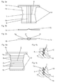
- FIGS. 1b and 1c respectively showing the finished lamination sheet 1 intended for insertion into the vulcanization mold.
- the lamination sheet 1 is made of a flat, stamped sheet 1, which is shown in Fig. 1a, by folding or bending around a fold line 2.
- the unfolded lamella plate 1 has on both sides of the fold line 2 two almost congruent sections 1a, 1b in the shape of isosceles trapezoids.
- the section 1a has at its outer end region two elongate rectangular projections 1c, wherein here one of the fastening portions 1d of the lamella plate 1 is connected.
- the lamella plate 1 is anchored with its fold line 2 opposite mounting portions 1d in the vulcanization mold, for example, inserted into the milled slot of the vulcanization mold and fixed or poured into molds.
- the distance a in Fig. 1b corresponds to the maximum depth of the resulting in the tread of the tire to be vulcanized incision.
- the side lugs 1c form in the tread of the tire shallow and narrow incision portions with which the relevant incision preferably opens into a groove or groove.
- the incision sections formed by the lateral lugs 1c are only half as wide as the middle section of the incision, which is formed by a double lamella plate.
- the Side sections 1c can be created at any height, in particular it can be provided that they form a uniform substantially rectangular or trapezoidal surface with the section 1a. In this case, even the narrow sections of the shaped incisions to reach the maximum provided incision depth.
- the folded slat plate 1 can be additionally embossed, so that, for example, alternately elevations and depressions are formed, which result in zig-zag running incisions in the tread in plan view.
- the drawing figures 2a, 2b, 3a, 3b, 4a to 4c, 5a, 5b, 6a to 6c, 7a, 7b and 8a and 8b show variants of the embodiment shown in Fig. 1a to 1c of a lamination sheet 1.
- Slat plate 1 in each case the basic form of Slat plate 1 is left the same and therefore it has each slat plate 1 congruent running and in contact trapezoidal sections 1a, 1b and two lateral sections 1c, which are provided on the one section 1a.
- the lamella plates 1 therefore form incisions which have their greatest width and their maximum depth in the middle region and are made narrow and shallow in the lateral regions.
- the fastening portions 1d for anchoring the finished bent laminations 1 in the vulcanization mold are each indicated by broken lines.
- Fig. 2a and 2b show an embodiment in which in each slat sheet portion 1a, 1b approximately centrally a recess 3, which is embodied here in the form of a hexagon, is embossed.
- the two recesses 3 are created in unfolded lamella plate 1 in the same direction, so that after folding along the fold line 2 and the joining of the two sheet sections 1a, 1b, the wells 3 together enclose an extension 4, as shown in Fig. 2b in longitudinal section.
- the outer contour of a tread block 10 of the tread of a tire is indicated, so that it can be seen that the outer surface of the lamella plate 1 form the inner boundary surfaces of the shaped incision.
- the lamination sheet 1 is pre-stamped in the unfolded state, here by a triangular groove 5 running continuously over both sections 1 a, 1 b of the still unfolded sheet metal 1.
- the plan view of the unfolded lamination sheet 1 in FIG Fig. 3c shows the groove 5 from above. After bending or folding of the lamella sheet 1, this has in plan view the shape shown in Fig. 3b.
- the sections 1 a and 1 b of the lamella plate 1 in the folded state include a plan view parallelogramm- or rombenförmigen extension 11 through which in the incision in the tire also an extension is generated, which extends to the periphery of the tread.
- FIGS. 4b and 4c show a further embodiment of the invention, in which the unfolded lamella sheet 1 is provided on each sheet metal section 1a, 1b at a small acute angle to the folding line 2, each with two recesses 6, produced by impressing.
- the depressions 6 in the one sheet metal section 1a are symmetrical to the recesses 6 in the other sheet metal section 1b, based on the folding line 2a, so that the finished, folded laminated sheet 1 has the mutual arrangement of extensions 7 shown in FIGS. 4b and 4c, for example.
- these depressions 6 or the extensions 7 that result from them form corresponding extensions in the shaped recess.
- Fig. 4b and 4c is illustrated in each case by the indicated profile block 10, that the outer contour of the respective lamella plate 1 corresponds to the wall contour of the formed incision.
- FIG. 5a and 5b of a sheet metal section 1b is centered and perpendicular to the fold line 2 except that over the course of the recess 8 of the section 1b is interrupted.
- FIG. 5b illustrates this with reference to a plan view of the folded lamella plate 1.
- FIGS. 6a to 6c show a variant in which a number of holes 9 are punched out in the one lamination sheet section 1a.
- the holes 9 may have different shapes and dimensions, in the illustrated embodiment, three circular holes 9 and an elongated hole 9 are provided.
- Fig. 6b shows a longitudinal section through the finished folded lamellar sheet 1 along the line AA of Fig. 6a
- Fig. 6c shows a section along the line BB of Fig. 6a, wherein in Fig. 6b and 6c in each case also a profile block 10 is indicated .
- the shaped incisions are narrower, since locally rubber material can enter here.
- the wider portions of the indent make the block 10 softer, in the areas with holes 9 the block 10 is stiffened.
- FIGS. 7a and 7b A combination of holes 9 and recesses 3 in both sections 1a, 1b of the lamella plate 1 are shown in FIGS. 7a and 7b.
- Each section 1a, 1b is in each case provided with a recess 3 and in each case a hole 9, the triangular-shaped hole 9 and the triangular recess 3 corresponding in the sections 1a, 1b, such that, as FIG. 7b shows, with the lamination plate folded together 1 the triangular depression 3 with the triangular hole 9 hits each other and creates a bend in the incision course.
- FIG. 8a and 8b Another way to influence the rigidity of a profile block by a special incision design, Fig. 8a and 8b.
- the unfolded lamella plate 1 has in the one lamella plate portion 1a two recesses 3, which are executed in the same direction, in the second lamella plate portion 1b are another equally oriented recess 3 and an oppositely executed recess 3 is provided.
- Fig. 8b shows the folded sheet metal plate 1 and an indicated profile block 10, wherein it can be seen here that two recesses 3 a local extension 4 in shaped incision, the two further recesses 3 in the vertical course of the incision yield a bend.
- the lamellar sheet 1 ' has two congruently executed trapezoidal sections 1'a, 1'b and two lateral constructions, which are congruent and are in contact with each other after folding Sections 1'a provided at section 1'a.
- the lamination sheet 1 ' centered on the portion 1'b, has a further portion 1'e whose trapezoidal base area is smaller than the base area of the portions 1'a and 1'b the illustrated embodiment is about one third of the area of the sections 1'a and 1'b.
- the dimension a of the trapezoidal section 1'e in the unfolded state is selected in the embodiment shown such that, after the folding (FIGS. 9e to 9g), the height of the section 1'e and with the heights of the sections 1'a and 1 ' b match.
- the sections 1'a and 1'b are foldable on one another about a fold line 2 ', the section 1'e is around a further fold line 2 "parallel to the fold line 2' and also along the free areas of the peripheral edge of the section 1'b 9b and 9c show the lamination sheet 1 'after the folding process has been carried out around the fold line 2', Fig. 9b in a side view, Fig. 9c in a plan view, Fig. 9d to 9g show this Lamination sheet 1 'after performing the second folding operation, the folding of the portion 1'e around the fold line 2''Fig. 9d and 9e show analogous to Fig. 9b and 9c views from one side, Fig.
- 9f and 9g views of 9f of the section 1'e which is folded onto the section 1'a and is in contact with it can be recognized by means of a lamella plate 1 'designed in this way in the finished tire, which incision is made on the other side of the lamella plate 1' has three sections of different width, twoitli edge portions, which are the narrowest portions, to these subsequent wider portions and one in the Incision center located portion which is widest, corresponding to the sheet thicknesses of the three sections 1'a, 1'b and 1'e.
- Figs. 10a to 10f show a modification of the embodiment shown in Figs. 9a to 9g.
- two sections 1'e are provided, which can be folded around the second fold line 2 "The two sections 1'e are of equal size in this embodiment variant and symmetrically attached to section 1'b.
- Figures 10b to 10f show views of the lamination sheet 1 'after completion of the folding operations, with Figures 10b and 10d being side views and Figures 10c and 10f being plan views having three different widths and in a certain arrangement, corresponding to the lamination sheet thicknesses as shown in Fig. 10c and 10f, has.
- the fastening sections for anchoring the finished folded lamellar sheets 1 'in the vulcanization mold are not shown, but can be designed analogously to the previous design variants-with interruptions in the sections 1'e.
- the lamella plates 1 'according to FIGS. 9d to 9g and 10a to 10f can be embossed subsequently to produce zigzag-shaped cuts in tires, for example in plan view.
- the simple thickness of the laminations is chosen between 0.1 mm and 1 mm, in particular between 0.3 mm and 0.6 mm.
- the cuts in the tire therefore have sections of this width and sections of twice the width.
Abstract
Description
Die Erfindung betrifft eine Form mit Formteilen zur Ausformung der Profilierung des Laufstreifens eines Fahrzeugluftreifens mit Feineinschnitten, mittels in den Formteilen verankerter Lamellenbleche. Die Erfindung betrifft ferner einen in einer derartigen Form vulkanisierten Fahrzeugluftreifen.The invention relates to a mold with moldings for forming the profiling of the tread of a pneumatic vehicle tire with sipes, by means anchored in the moldings lamellar sheets. The invention further relates to a vehicle pneumatic tire vulcanized in such a form.
Feineinschnitten im Laufflächenprofil von Fahrzeugluftreifen, insbesondere von Reifen, die für den Einsatz unter winterlichen Fahrbedingungen geeignet sein sollen, kommt eine besondere Bedeutung zu. Feineinschnitte stellen insbesondere Griffkanten zur Verfügung, die für einen guten Griff des Reifens auf schneeigen oder eisigen Fahrbahnen von Bedeutung sind. Dabei kommt es bei der Ausführung von Feineinschnitten auch darauf an, die Biegesteifigkeit der Profilelemente, beispielsweise der Blöcke, derart zu beeinflussen und einzustellen, dass der Reifen auch eine gute Traktion auf winterlichen Fahrbahnen und ein gutes Bremsvermögen sowohl auf winterlichen als auch auf trockenen und nassen Fahrbahnen aufweist.Fine cuts in the tread pattern of pneumatic vehicle tires, in particular of tires, which should be suitable for use under wintry driving conditions, is of particular importance. Fine cuts, in particular, provide gripping edges which are important for good grip of the tire on snowy or icy road surfaces. It also comes in the execution of sipes on it to influence the flexural rigidity of the profile elements, such as blocks, and adjust so that the tire also good traction on wintry roads and a good braking ability on both winter and dry and wet Roadways has.
Feineinschnitte werden üblicherweise dadurch erzeugt, dass Lamellenbleche in die Vulkanisationsform eingegossen oder in der Vulkanisationsform in speziell eingefrästen Schlitzen verankert werden, sodass sich die Lamellenbleche von der Formoberfläche in den Raum zur Aufnahme und Ausformung des Reifenrohlings hinein erstrecken. Der Reifenrohling wird üblicherweise zur Ausformung des Profils mittels eines Heizbalges gegen die mit Lamellenblechen auf diese Weise bestückte Formoberfläche gepresst, wodurch die Lauffläche des Fahrzeugluftreifens entsprechend der Profilierung der Formoberfläche profiliert wird. Die Lamellenbleche erzeugen hierbei schmale Einschnitte im Laufflächenprofil des Fahrzeugluftreifens.Fine cuts are usually made by finning lamella sheets into the vulcanization mold or anchoring them in the vulcanization mold in specially milled slots so that the louver sheets extend from the mold surface into the space for receiving and forming the green tire. The green tire is usually used to shape the profile by means of a bladder against those equipped with laminations in this way Mold surface pressed, whereby the tread of the pneumatic vehicle tire is profiled according to the profiling of the mold surface. The lamellar plates produce narrow cuts in the tread pattern of the pneumatic vehicle tire.
Die Erzeugung von sehr schmalen Einschnitten mit Lamellenblechen mit einer Dicke von weniger als 0,4 mm erfordert die Herstellung von entsprechend gefrästen schmalen Schlitzen in der Vulkanisationsform, ist daher mit einem höheren Aufwand verbunden und nur begrenzt möglich.The production of very narrow cuts with laminations with a thickness of less than 0.4 mm requires the production of appropriately milled narrow slits in the vulcanization mold, is therefore associated with a higher cost and limited.
Aus der
Aus der
Der Erfindung liegt die Aufgabe zugrunde, in einfacher Weise die Herstellung von Feineinschnitten in Laufflächen von Fahrzeugluftreifen zu ermöglichen, welche Einschnitte eine gezielte Beeinflussung der Biegesteifigkeit der Profilelemente im Laufstreifen des Reifens gestatten sollen und welche vorzugsweise eine variierende Einschnittbreite aufweisen.The invention has for its object to easily allow the production of sipes in treads of pneumatic vehicle tires, which cuts should allow a targeted influence on the flexural rigidity of the tread elements in the tread of the tire and which preferably have a varying incision width.
Gelöst wird die gestellte Aufgabe erfindungsgemäß durch Lamellenbleche mit zumindest zwei aufeinander gefalteten Blechabschnitten, welche eine übereinstimmende radiale Erstreckung bis zur Forminnenseite aufweisen und mit Befestigungsabschnitten an ihren freien Endbereichen in der Form verankert sind.The object is achieved according to the invention by lamella plates with at least two folded sheet metal sections, which have a matching radial extent to the inner side of the mold and are anchored with mounting portions at their free end portions in the mold.
Bevorzugt weisen dabei die aufeinander gefalteten Abschnitte unterschiedlich große Flächen auf.In this case, the sections folded onto one another preferably have surfaces of different sizes.
Durch einfaches Falten oder Biegen von Lamellenblechen bzw. Abschnitten derselben weisen diese im aufeinander gefalteten Bereich eine doppelte Blechdicke auf. In Bereich(en), wo kein doppeltes Lamellenblech vorliegt, wird bzw. werden im Laufstreifen des Reifens schmale Einschnittabschnitte erzeugt. Dabei ist es möglich, den Feineinschnitt im Reifen durch die entsprechende Gestaltung von Lamellenblechabschnitten sehr variabel hinsichtlich der Einschnittbreite zu gestalten. Dadurch lassen sich mit erfindungsgemäßen Lamellenblechen im Reifen Feineinschnitte herstellen, die in erwünschter Weise die Biegesteifigkeit der Profilelemente, insbesondere der Profilblöcke, beeinflussen. Beispielsweise sind Einschnitte erzeugbar, die an ihren Einmündungsbereichen zu Umfangsnuten schmäler oder dicker ausgeführt sind als in ihrem mittleren Abschnitt.By simply folding or bending of laminations or sections thereof, these have a double sheet thickness in the folded-together region. In area (s) where no double lamination sheet is present, narrow cut-in portions are created in the tread of the tire. It is possible to make the fine incision in the tire by the corresponding design of slat plate sections very variable in terms of the incision width. As a result, it is possible to produce fine incisions in the tire with lamella plates according to the invention, which in the desired manner influence the bending stiffness of the profile elements, in particular of the profile blocks. For example, incisions can be generated which are made narrower or thicker at their junction areas to circumferential grooves than in their middle section.
Bei einer bevorzugten, einfachen Ausführung der Erfindung sind die aufeinander gefalteten Abschnitte zumindest abschnittsweise deckungsgleich ausgeführt, wobei vorzugsweise der eine dieser Abschnitte mit zumindest einem weiteren Abschnitt die Fläche eines anderen, auf den ersten gefalteten Abschnittes überragt. Der mit einem derartigen Lamellenblech erzeugte Einschnitt im Laufstreifen eines Reifens kann somit in einem definierten Bereich bzw. Abschnitt breiter ausgeführt sein als in anderen definierten Abschnitten.In a preferred, simple embodiment of the invention, the sections folded onto one another are congruent at least in sections, wherein preferably one of these sections with at least one further section projects beyond the surface of another section folded onto the first section. The cut produced in the tread of a tire with such a lamella plate can thus be made wider in a defined area or section than in other defined sections.
Bei einer weiteren bevorzugten Ausführungsform der Erfindung weisen die aufeinander gefalteten Abschnitte und der bzw. die diese überragende(n) Abschnitt(e) unterschiedliche radiale und insbesondere auch unterschiedliche axiale Erstreckungen auf. Die gewählten Abmessungen für diese Abschnitte gestatten es, die Biegesteifigkeit der Profilelemente im Laufstreifen ganz gezielt zu beeinflussen.In a further preferred embodiment of the invention, the folded-together sections and the one or more protruding sections thereof Section (e) different radial and in particular also different axial extensions. The selected dimensions for these sections make it possible to influence the flexural rigidity of the tread elements in the tread in a very targeted manner.
Um Einschnitte im Reifen zu erzeugen, die gleichzeitig die Performance des Reifens auf Schnee und jene auf trockenen Fahrbahnen verbessern, werden Lamellenbleche mit drei oder mehr aufeinander gefalteten Blechabschnitten vorgesehen. Je nach Anordnung und Dimension der aufeinander gefalteten Blechabschnitte lassen sich hinsichtlich ihrer Breite sehr variabel ausgeführte Einschnitte im Reifen erzeugen. Besonders vorteilhaft ist es, Lamellenbleche zu verwenden, welche zwei oder mehr Bereiche mit zumindest zwei aufeinander gefalteten Blechabschnitten aufweisen. Auf diese Weise lassen sich Einschnitte erzeugen, die Abschnitte mit variierenden Breiten aufweisen.In order to produce cuts in the tire, which simultaneously improve the performance of the tire on snow and those on dry roads, lamellar plates are provided with three or more folded sheet metal sections. Depending on the arrangement and dimension of the folded sheet metal sections can be produced in terms of their width very variable executed cuts in the tire. It is particularly advantageous to use lamination plates which have two or more areas with at least two folded sheet metal sections. In this way, cuts can be made having sections of varying widths.
Um solche Einschnitte auszubilden, weisen die noch ungefalteten Lamellenbleche zumindest zwei Faltlinien für Blechabschnitte auf. Diese Faltlinien verlaufen bevorzugt parallel zueinander. Dies erleichtert eine definierte Ausführung der Lamellenblechabschnitte und deren Faltung.In order to form such incisions, the still unfolded lamination plates have at least two fold lines for sheet metal sections. These fold lines preferably run parallel to one another. This facilitates a defined embodiment of the lamination sheet sections and their folding.
Von besonderem Vorteil ist bei der Erfindung, dass sich die Steifigkeit der Profilelemente bei fortschreitendem Laufstreifenabrieb ebenfalls gezielt beeinflussen lässt, insbesondere dadurch, dass die Lamellenbleche, welche diese Einschnitte erzeugen, derart ausgeführt werden, dass zumindest einer der aufeinander gefalteten Abschnitte vor der Faltung durch Prägung oder Stanzung strukturiert wird. Durch eine Prägung kann beispielsweise zumindest eine örtliche Vertiefung, Nut oder dergleichen gebildet werden, durch Stanzung können Löcher und/oder Ausnehmungen erstellt werden.It is particularly advantageous in the invention that the stiffness of the profile elements can also be selectively influenced with progressive tread abrasion, in particular by the fact that the lamella plates which produce these incisions, are carried out such that at least one of the folded portions before embossing by folding or punching is structured. By embossing, for example, at least one local depression, groove or the like can be formed, holes and / or recesses can be created by punching.
Auch die gegenseitige Anordnung der Vertiefungen, Nuten, Löcher und Ausnehmungen in den zusammengefalteten Abschnitten ist von Bedeutung für die Wirkung der gebildeten Einschnitte auf die Steifigkeit des Profilelementes bei vorschreitendem Abrieb. So kann die gegenseitige Anordnung derart erfolgen, dass Vertiefungen oder Nuten zwischen sich Erweiterungen einschließen, die in den gebildeten Einschnitten ebenfalls Erweiterungen ergeben. Alternativ können Vertiefungen oder Nuten in den beiden aufeinander gefalteten Abschnitten gemeinsam Einbuchtungen oder Biegungen im Verlauf des Lamellenblechs ergeben.The mutual arrangement of the recesses, grooves, holes and recesses in the folded portions is of importance for the effect of the incisions formed on the stiffness of the profile element at progressive abrasion. Thus, the mutual arrangement can be such that recesses or grooves between them include extensions that also result in extensions in the incisions formed. Alternatively, depressions or grooves in the two folded-together sections can together give indentations or bends in the course of the lamella plate.
Erfindungsgemäße Lamellenbleche lassen sich bei aufeinander gefalteten Abschnitten zusätzlich prägen, insbesondere können auf diese Weise Lamellenbleche mit zick-zack- oder wellenförmigen Erhebungen und Vertiefungen erzeugt werden, die im fertigen Reifen in Draufsicht wellen- bzw. zick-zackförmig verlaufende Einschnitte ergeben.Laminated metal sheets according to the invention can additionally be embossed with sections folded onto one another, in particular laminating sheets with zigzag or wave-shaped elevations and depressions can be produced in this way, which result in wavy or zigzag-shaped cuts in the finished tire in the finished tire.
Die Erfindung betrifft schließlich einen Fahrzeugluftreifen, welcher in einer Form und mit erfindungsgemäß ausgeführten Lamellenblechen vulkanisiert worden ist.Finally, the invention relates to a pneumatic vehicle tire which has been vulcanized in a mold and with lamella plates designed according to the invention.
Weitere Merkmale, Vorteile und Einzelheiten der Erfindung werden anhand der Zeichnung, die schematisch mehrere Ausführungsbeispiele darstellt, näher beschrieben. Dabei zeigen
- Fig. 1a bis Fig. 1c eine Ausführungsform eines Lamellenblechs, Fig. 1a eine Ansicht des ungefalteten Lamellenblechs, Fig. 1b eine Ansicht des gefalteten Lamellenblechs, Fig. 1c eine Draufsicht auf das gefaltete Lamellenblech,
- Fig. 2a und Fig. 2b Ansichten einer weiteren Ausführungsform eines Lamellenblechs, Fig. 2a das ungefaltete Lamellenblech, Fig. 2b einen Längsschnitt des gefalteten Lamellenblechs,
- Fig. 3a bis Fig. 3c Ansichten einer weiteren Ausführungsform eines Lamellenblechs, Fig. 3a das ungefaltete Lamellenblech, Fig. 3b eine Draufsicht auf das ungefaltete Lamellenblech, Fig. 3c eine Draufsicht auf das gefaltete Lamellenblech,
- Fig. 4a bis Fig. 4c Ansichten einer weiteren Ausführungsform, Fig. 4a das ungefaltete Lamellenblech, Fig. 4b und Fig. 4c Längsschnitte durch das gefaltete Lamellenblech,
- Fig. 5a und Fig. 5b Ansichten einer anderen Ausführungsform, Fig. 5a das ungefaltete Lamellenblech, Fig. 5b eine Draufsicht auf das gefaltete Lamellenblech,
- Fig. 6a bis Fig. 6c Ansichten einer weiteren Ausführungsform eines Lamellenblechs, Fig. 6a das ungefaltete Lamellenblech, Fig. 6b und Fig. 6c Längsschnitte durch das gefaltete Lamellenblech,
- Fig. 7a und Fig. 7b eine weitere Ausführungsvariante eines Lamellenblechs, Fig. 7a das ungefaltete Lamellenblech, Fig. 7b einen Längsschnitt durch das gefaltete Lamellenblech,
- Fig. 8a und Fig. 8b eine andere Ausführungsvariante eines Lamellenblechs, Fig. 8a das ungefaltete Lamellenblech, Fig. 8b eine Längsschnitt durch das gefaltete Lamellenblech,
- Fig. 9a bis 9g Ansichten einer weiteren Ausführungsvariante eines Lamellenblechs, Fig. 9a das ungefaltete Lamellenblech, Fig. 9b und 9c Ansichten des Lamellenblechs nach Durchführung einer ersten Faltung, Fig. 9d bis 9g Ansichten des komplett gefalteten Lamellenblechs,
- Fig. 10a bis 10f ebenfalls Ansichten einer Ausführungsvariante eines Lamellenblechs, Fig. 10a das ungefaltete Lamellenblech und Fig. 10b bis 10c Ansichten des komplett gefalteten Lamellenblechs.
- 1a shows a view of the unfolded lamellar plate, FIG. 1b shows a view of the folded lamella plate, FIG. 1c shows a plan view of the folded lamella plate,
- 2 a and 2b show views of a further embodiment of a lamination plate, FIG. 2 a shows the unfolded lamination plate, FIG. 2 b shows a longitudinal section of the folded lamination plate,
- 3a to 3c show views of a further embodiment of a lamella plate, FIG. 3a the unfolded lamella plate, FIG. 3b a plan view of the unfolded lamella plate, FIG. 3c a plan view of the folded lamella plate,
- 4 a to 4 c show views of a further embodiment, FIG. 4 a shows the unfolded lamination sheet, FIGS. 4 b and 4 c show longitudinal sections through the folded lamination sheet,
- 5 a and 5b show views of another embodiment, FIG. 5 a shows the unfolded lamination sheet, FIG. 5 b shows a plan view of the folded lamination sheet,
- 6a to 6c are views of a further embodiment of a lamination sheet, FIG. 6a is the unfolded lamination sheet, FIG. 6b and FIG. 6c are longitudinal sections through the folded lamination sheet, FIG.
- 7a and FIG. 7b show a further embodiment of a lamella plate, FIG. 7a the unfolded lamella plate, FIG. 7b a longitudinal section through the folded lamella plate, FIG.
- 8a and FIG. 8b another variant of a lamella plate, FIG. 8a the unfolded lamella plate, FIG. 8b a longitudinal section through the folded lamella plate, FIG.
- 9a to 9g views of a further embodiment variant of a lamella plate, FIG. 9a the unfolded lamella plate, FIGS. 9b and 9c views of the lamella plate after carrying out a first folding, FIGS. 9d to 9g views of the completely folded lamella plate,
- FIGS. 10a to 10f likewise views of a variant embodiment of a lamella plate, FIGS. 10a the unfolded lamella plate and FIGS. 10b to 10c views of the completely folded lamella plate.
Lamellenbleche dienen zur Herstellung von Feineinschnitten in der Lauffläche eines Fahrzeugluftreifens und werden zu diesem Zweck in eingefrästen Schlitzen von Laufflächensegmenten einer Vulkanisationsform eingesetzt und befestigt. In den Zeichnungsfiguren sind Bestandteile der Vulkanisationsform nicht dargestellt. Mit unterbrochenen Linien sind jene Abschnitte der Lamellenbleche angedeutet, mit welchen diese in der Vulkanisationsform verankert werden.Laminated plates are used to produce fine cuts in the tread of a pneumatic vehicle tire and are used and fixed in milled slots of tread segments of a vulcanization mold for this purpose. In the Drawing figures are components of the vulcanization mold not shown. With broken lines those portions of the lamellar sheets are indicated with which they are anchored in the vulcanization mold.
Fig. 1a bis 1c zeigen eine Basisvariante eines erfindungsgemäßen Lamellenblechs 1, wobei Fig. 1b und 1c jeweils das fertige, zum Einsetzen in die Vulkanisationsform vorgesehene Lamellenblech 1 zeigen. Das Lamellenblech 1 wird aus einem ebenen, gestanzten Blech 1, welches in Fig. 1a gezeigt ist, durch Falten bzw. Biegen um eine Faltlinie 2 hergestellt. Das ungefaltete Lamellenblech 1 weist beidseitig der Faltlinie 2 zwei nahezu deckungsgleich ausgeführte Abschnitte 1a, 1b in der Gestalt von gleichschenkeligen Trapezen auf. Der Abschnitt 1a weist an seinem äußeren Endbereich zwei langgestreckt rechteckförmige Ansätze 1c auf, wobei hier einer der Befestigungsabschnitte 1d des Lamellenblechs 1 anschließt. Fig. 1b und 1c zeigen das gefaltete Lamellenblech 1, die beiden Abschnitte 1a, 1b sind deckungsgleich aufeinander gefaltet und in Kontakt miteinander. Das Lamellenblech 1 wird mit seinen der Faltlinie 2 gegenüber liegenden Befestigungsabschnitten 1d in der Vulkanisationsform verankert, beispielsweise in den gefrästen Schlitz der Vulkanisationsform eingesetzt und befestigt oder bei Gussformen eingegossen. Der Abstand a in Fig. 1b entspricht der maximalen Tiefe des in der Lauffläche des zu vulkanisierenden Reifens entstehenden Einschnittes. Zur Ausformung und Vulkanisation wird der noch rohe Reifen in die Vulkanisationsform eingesetzt und mittels eines Heizbalges in bekannter Weise radial expandiert und dabei gegen die Vulkanisationsform gepresst, so dass das Kautschukmaterial des Laufstreifens in die Lamellenbleche und die weiteren, nicht gezeigten Profilierungen der Vulkanisationsform gedrückt wird.1a to 1c show a basic variant of a
Die seitlichen Ansätze 1c bilden im Laufstreifen des Reifens seichte und schmale Einschnittabschnitte, mit welchen der betreffende Einschnitt bevorzugt in eine Rille oder Nut einmündet. Die von den seitlichen Ansätzen 1c gebildeten Einschnittabschnitte sind nur halb so breit wie der mittlere Abschnitt des Einschnittes, welcher durch ein doppeltes Lamellenblech gebildet wird. Die seitlichen Abschnitte 1c können in beliebiger Höhe erstellt sein, insbesondere kann vorgesehen sein, dass sie mit dem Abschnitt 1a eine einheitliche im Wesentlichen rechteckige bzw. trapezförmige Fläche bilden. In diesem Fall reichen auch die schmalen Abschnitte der ausgeformten Einschnitte bis auf die maximal vorgesehene Einschnitttiefe. Das gefaltete Lamellenblech 1 kann zusätzlich geprägt werden, sodass beispielweise abwechselnd Erhebungen und Vertiefungen gebildet werden, die im Laufstreifen in Draufsicht zick-zack-förmig verlaufende Einschnitte ergeben.The side lugs 1c form in the tread of the tire shallow and narrow incision portions with which the relevant incision preferably opens into a groove or groove. The incision sections formed by the lateral lugs 1c are only half as wide as the middle section of the incision, which is formed by a double lamella plate. The
Die Zeichnungsfiguren 2a, 2b, 3a, 3b, 4a bis 4c, 5a, 5b, 6a bis 6c, 7a, 7b sowie 8a und 8b zeigen Varianten der in Fig. 1a bis 1c gezeigten Ausführungsform eines Lamellenblechs 1. Dabei ist jeweils die Grundform des Lamellenblechs 1 gleich gelassen und es weist daher jedes Lamellenblech 1 deckungsgleich ausgeführte und in Kontakt stehende trapezförmige Abschnitte 1a, 1b und zwei seitliche Abschnitte 1c auf, die an dem einen Abschnitt 1a vorgesehen sind. Die Lamellenbleche 1 bilden daher Einschnitte, die im mittleren Bereich ihre größte Breite und ihre maximale Tiefe aufweisen und in den seitlichen Bereichen schmal und seicht ausgeführt sind. Die Befestigungsabschnitte 1d zum Verankern der fertig gebogenen Lamellenbleche 1 in der Vulkanisationsform sind jeweils mit unterbrochenen Linien angedeutet.The drawing figures 2a, 2b, 3a, 3b, 4a to 4c, 5a, 5b, 6a to 6c, 7a, 7b and 8a and 8b show variants of the embodiment shown in Fig. 1a to 1c of a
Fig. 2a und 2b zeigen eine Ausführungsform, bei der in jedem Lamellenblechabschnitt 1a, 1b etwa mittig eine Vertiefung 3, die hier in der Form eines Sechseckes ausgeführt ist, eingeprägt ist. Die beiden Vertiefungen 3 werden bei ungefaltetem Lamellenblech 1 in übereinstimmender Richtung erstellt, sodass nach dem Falten entlang der Faltlinie 2 und dem Aufeinanderfügen der beiden Blechabschnitte 1a, 1b die Vertiefungen 3 gemeinsam eine Erweiterung 4 umschließen, wie es Fig. 2b im Längsschnitt zeigt. In Fig. 2b ist auch die Außenkontur eines Profilblockes 10 der Lauffläche eines Reifens angedeutet, sodass ersichtlich ist, dass die Außenfläche des Lamellenblechs 1 die inneren Begrenzungsflächen des geformten Einschnittes bilden.Fig. 2a and 2b show an embodiment in which in each
Bei der in Fig. 3a bis 3c gezeigten Ausführungsvariante eines Lamellenblechs 1 ist das Lamellenblech 1 im ungefalteten Zustand vorgeprägt, hier durch eine über beide Abschnitte 1a, 1b des noch ungefalteten Blechs 1 durchgehend verlaufende dreieckförmige Nut 5. Die Draufsicht auf das ungefaltete Lamellenblech 1 in Fig. 3c zeigt die Nut 5 von oben. Nach dem Biegen bzw. Falten des Lamellenblechs 1 hat dieses in Draufsicht die in Fig. 3b gezeigte Form. Die Abschnitte 1a und 1b des Lamellenblechs 1 schließen im zusammengefalteten Zustand eine in Draufsicht parallelogramm- bzw. rombenförmigen Erweiterung 11 ein, durch welche im Einschnitt im Reifen ebenfalls eine Erweiterung erzeugt wird, die bis zur Peripherie des Laufstreifens verläuft.In the embodiment variant of a
Fig. 4a bis 4c zeigen eine weitere Ausführungsform der Erfindung, bei der das ungefaltete Lamellenblech 1 auf jedem Blechabschnitt 1a, 1b unter einem kleinen spitzen Winkel zur Faltlinie 2 jeweils mit zwei Vertiefungen 6, erzeugt durch Einprägen, versehen wird. Die Vertiefungen 6 in dem einen Blechabschnitt 1a sind, bezogen auf die Faltlinie 2a, symmetrisch zu den Vertiefungen 6 im anderen Blechabschnitt 1b erstellt, sodass das fertige, gefaltete Lamellenblech 1 die beispielweise in Fig. 4b und 4c gezeigte gegenseitige Anordnung von Erweiterungen 7 aufweist. Im fertigen Reifen bilden diese Vertiefungen 6 bzw. die durch sie entstehenden Erweiterungen 7 entsprechende Erweiterungen im geformten Einschnitt. In Fig. 4b und 4c wird in durch den jeweils angedeuteten Profilbock 10 veranschaulicht, dass die Außenkontur des jeweiligen Lamellenblechs 1 der Wandkontur des gebildeten Einschnittes entspricht.4a to 4c show a further embodiment of the invention, in which the unfolded
Bei der in Fig. 5a und 5b gezeigten Ausführungsvariante ist der eine Blechabschnitt 1b mittig und senkrecht zur Faltlinie 2 ausgenommen, sodass über den Verlauf der Ausnehmung 8 der Abschnitt 1b unterbrochen ist. Im gefalteten Zustand weist daher das Lamellenblech 1 an der Stelle der Ausnehmung 8 eine Unterbrechung der doppelten Blechstärke auf, sodass der geformte Einschnitt an dieser Stelle ebenfalls entsprechend schmäler ausgeführt ist. Fig. 5b verdeutlicht dies anhand einer Draufsicht auf das gefaltete Lamellenblech 1.In the embodiment shown in Fig. 5a and 5b of a
Fig. 6a bis Fig. 6c zeigen eine Ausführungsvariante, bei der in dem einen Lamellenblechabschnitt 1a eine Anzahl von Löchern 9 ausgestanzt ist. Die Löcher 9 können unterschiedliche Formen und Abmessungen aufweisen, bei der dargestellten Ausführungsform sind drei kreisrunde Löcher 9 und ein längliches Loch 9 vorgesehen. Fig. 6b zeigt einen Längsschnitt durch das fertig gefaltete Lamellenblech 1 entlang der Linie A-A der Fig. 6a, Fig. 6c zeigt einen Schnitt entlang der Linie B-B der Fig. 6a, wobei in Fig. 6b und 6c jeweils auch ein Profilblock 10 angedeutet ist. Im Bereich der Löcher 9 sind somit die geformten Einschnitte schmäler, da hier lokal Gummimaterial eintreten kann. Mit zunehmendem Abrieb des Profilblockes 10 bzw. Laufstreifens kommen daher unterschiedliche Charakteristiken des Einschnittes im Profilblock 10 zum Tragen. Die breiteren Abschnitte des Einschnittes machen den Block 10 weicher, in den Bereichen mit Löchern 9 wird der Block 10 versteift.FIGS. 6a to 6c show a variant in which a number of
Eine Kombination von Löchern 9 und Vertiefungen 3 in beiden Abschnitten 1a, 1b des Lamellenblechs 1 zeigen Fig. 7a und 7b. Jeder Abschnitt 1a, 1b ist jeweils mit einer Vertiefung 3 und jeweils einem Loch 9 versehen, wobei das dreieckförmige Loch 9 und die dreieckförmige Vertiefung 3 in den Abschnitten 1a, 1b korrespondieren, derart, dass, wie es Fig. 7b zeigt, bei zusammengefaltetem Lamellenblech 1 die dreieckförmige Vertiefung 3 mit dem dreieckförmigen Loch 9 aufeinander trifft und eine Biegung im Einschnittverlauf erzeugt.A combination of
Eine weitere Möglichkeit, die Steifigkeit eines Profilblocks durch eine besondere Einschnittgestaltung zu beeinflussen, zeigen Fig. 8a und 8b. Das ungefaltete Lamellenblech 1 weist in dem einen Lamellenblechabschnitt 1a zwei Vertiefungen 3 auf, die in übereinstimmender Richtung ausgeführt sind, im zweiten Lamellenblechabschnitt 1b sind eine weitere gleichermaßen orientierte Vertiefung 3 und eine entgegengesetzt ausgeführte Vertiefung 3 versehen. Fig. 8b zeigt das zusammengefaltete Lamellenblech 1 sowie einen angedeuteten Profilblock 10, wobei hier zu erkennen ist, dass zwei Vertiefungen 3 eine örtliche Erweiterung 4 im geformten Einschnitt, die beiden weiteren Vertiefungen 3 im Vertikalverlauf des Einschnittes eine Biegung ergeben.Another way to influence the rigidity of a profile block by a special incision design, Fig. 8a and 8b. The unfolded
Bei den in den Figuren 9a bis 9g und 10a bis 10f gezeigten Ausführungsvarianten der Erfindung weist das Lamellenblech 1' analog zu den vorhergehenden Ausführungsvarianten zwei deckungsgleich ausgeführte und nach dem Falten miteinander in Kontakt stehende trapezförmige Abschnitte 1'a, 1'b auf sowie zwei seitliche Abschnitte 1'a, die am Abschnitt 1'a vorgesehen sind, auf.In the embodiment variants of the invention shown in FIGS. 9a to 9g and 10a to 10f, the lamellar sheet 1 'has two congruently executed trapezoidal sections 1'a, 1'b and two lateral constructions, which are congruent and are in contact with each other after folding Sections 1'a provided at section 1'a.
Bei der in Fig. 9a bis 9g gezeigten Ausführungsvariante weist das Lamellenblech 1', am Abschnitt 1'b mittig angesetzt einen weiteren Abschnitt 1'e auf, dessen trapezförmige Grundfläche kleiner ist als die Grundfläche der Abschnitte 1'a und 1'b, bei der dargestellten Ausführungsform etwa ein Drittel der Fläche der Abschnitte 1'a und 1'b beträgt. Die Abmessung a des trapezförmigen Abschnittes 1'e im ungefalteten Zustand wird bei der gezeigten Ausführung so gewählt, dass nach der Faltung (Fig. 9e bis 9g) die Höhe des Abschnitts 1'e und mit den Höhen der Abschnitte 1'a und 1'b übereinstimmen. Die Abschnitte 1'a und 1'b sind um eine Faltlinie 2' aufeinander faltbar, der Abschnitt 1'e ist um eine weitere Faltlinie 2", die parallel zur Faltlinie 2'und auch entlang der freien Bereiche der Randkante des Abschnittes 1'b verläuft, auf den Abschnitt 1'a faltbar. Fig. 9b und 9c zeigen das Lamellenblech 1' nach dem Durchführen des Faltvorganges um die Faltlinie 2', Fig. 9b in Seitenansicht, Fig. 9c in Draufsicht. Fig. 9d bis 9g zeigen das Lamellenblech 1' nach dem Durchführen des zweiten Faltvorganges, dem Falten des Abschnittes 1'e um die Faltlinie 2''. Fig. 9d und 9e zeigen analog zu Fig. 9b und 9c Ansichten von der einen Seite, Fig. 9f und 9g Ansichten von der anderen Seite des Lamellenblechs 1', insbesondere ist in Fig. 9f der auf den Abschnitt 1'a gefaltete und mit diesem in Kontakt stehende Abschnitt 1'e erkennbar. Durch ein derart ausgeführtes Lamellenblech 1' wird im fertigen Reifen ein Einschnitt erzeugt, der drei Abschnitte unterschiedlicher Breite aufweist, zwei seitliche Randabschnitte, die die schmälsten Abschnitte sind, an diese anschließende breitere Abschnitte und einen in der Einschnittmitte befindlichen Abschnitt, welche am breitesten ist, entsprechend den Blechstärken der drei Abschnitte 1'a, 1'b und 1'e.In the embodiment variant shown in FIGS. 9a to 9g, the lamination sheet 1 ', centered on the portion 1'b, has a further portion 1'e whose trapezoidal base area is smaller than the base area of the portions 1'a and 1'b the illustrated embodiment is about one third of the area of the sections 1'a and 1'b. The dimension a of the trapezoidal section 1'e in the unfolded state is selected in the embodiment shown such that, after the folding (FIGS. 9e to 9g), the height of the section 1'e and with the heights of the sections 1'a and 1 ' b match. The sections 1'a and 1'b are foldable on one another about a fold line 2 ', the section 1'e is around a
Fig. 10a bis 10f zeigen eine Abwandlung der in Fig. 9a bis 9g gezeigten Ausführungsform. Anstelle eines einzigen Abschnittes 1'e sind bei dieser Ausführungsvariante zwei Abschnitte 1'e vorgesehen, die um die zweite Faltlinie 2" faltbar sind. Die beiden Abschnitte 1'e sind bei dieser Ausführungsvariante gleich groß ausgeführt und symmetrisch am Abschnitt 1'b angesetzt. Fig. 10b bis 10f zeigen Ansichten des Lamellenbleches 1' nach Komplettierung der Faltvorgänge, wobei Fig. 10b und 10d seitliche Ansichten und Fig. 10c und 10f Draufsichten sind. Durch ein derart ausgeführtes Lamellenblech 1' wird im fertigen Reifen ein Einschnitt erzeugt, welcher Abschnitte mit drei unterschiedlichen Breiten und in bestimmter Anordnung, entsprechend den Lamellenblechstärken wie sie in Fig. 10c und 10f ersichtlich sind, aufweist.Figs. 10a to 10f show a modification of the embodiment shown in Figs. 9a to 9g. Instead of a single section 1'e, in this embodiment variant, two sections 1'e are provided, which can be folded around the
Die Befestigungsabschnitte zum Verankern der fertig gefalteten Lamellenbleche 1' in der Vulkanisationsform sind nicht dargestellt, können jedoch analog zu den vorhergehenden Ausführungsvarianten - mit Unterbrechungen bei den Abschnitten 1'e - ausgebildet sein.The fastening sections for anchoring the finished folded lamellar sheets 1 'in the vulcanization mold are not shown, but can be designed analogously to the previous design variants-with interruptions in the sections 1'e.
Die Lamellenbleche 1' gemäß Fig. 9d bis 9g und 10a bis 10f können nachträglich geprägt werden, um beispielsweise in Draufsicht Zickzack-förmig verlaufende Einschnitte in Reifen zu erzeugen.The lamella plates 1 'according to FIGS. 9d to 9g and 10a to 10f can be embossed subsequently to produce zigzag-shaped cuts in tires, for example in plan view.
Auf analoge Weise ist es möglich, Lamellenbleche herzustellen, die mehr als drei aufeinander gefaltete Abschnitte aufweisen.In an analogous manner, it is possible to produce laminations having more than three sections folded on each other.
Die einfache Dicke der Lamellenbleche wird zwischen 0,1 mm und 1 mm, insbesondere zwischen 0,3 mm und 0,6 mm, gewählt. Die Einschnitte im Reifen weisen daher Abschnitte dieser Breite und Abschnitte der doppelten Breite auf.The simple thickness of the laminations is chosen between 0.1 mm and 1 mm, in particular between 0.3 mm and 0.6 mm. The cuts in the tire therefore have sections of this width and sections of twice the width.
Es ist eine Vielzahl von weiteren Variationen möglich. Insbesondere können Maßnahmen und Merkmale aus den beschriebenen und dargestellten Ausführungsformen auf vielfältige Weise miteinander kombiniert werden. Darüber hinaus können die Anzahl und die Form der Vertiefungen, Löcher, Nuten und dergleichen beliebig variiert werden.There is a variety of other variations possible. In particular, measures and features from the described and illustrated embodiments can be combined with each other in a variety of ways. In addition, the number and the shape of the recesses, holes, grooves and the like can be varied as desired.
- 11
- Lamellenblechlamination plate
- 1'1'
- Lamellenblechlamination plate
- 1a1a
- Abschnittsection
- 1'a1'a
- Abschnittsection
- 1b1b
- Abschnittsection
- 1'b1'b
- Abschnittsection
- 1c1c
- Ansatzapproach
- 1'c1'c
- Ansatzapproach
- 1'e1'E
- Abschnittsection
- 1d1d
- Befestigungsabschnittattachment section
- 22
- FaltfinieFaltfinie
- 2',2''2 ', 2' '
- Faltliniefold line
- 33
- Vertiefungdeepening
- 44
- Erweiterungextension
- 55
- Nutgroove
- 66
- Vertiefungdeepening
- 77
- Erweiterungenextensions
- 88th
- Ausnehmungrecess
- 99
- Lochhole
- 1010
- Profilblocktread block
- 1111
- Erweiterungextension
Claims (15)
gekennzeichnet durch
Lamellenbleche (1, 1') mit zumindest zwei aufeinander gefalteten Blechabschnitten (1a, 1b, 1'a, 1'b, 1'e), welche eine übereinstimmende radiale Erstreckung bis zur Forminnenseite aufweisen und mittels Befestigungsabschnitten (1d) an ihren freien Endbereichen in der Form verankert sind.Mold with molded parts for shaping the profiling of the tread of a pneumatic vehicle tire with sipes by means of lamella plates (1,1 ') anchored in the molded parts,
marked by
Slat plates (1, 1 ') with at least two folded sheet metal sections (1a, 1b, 1'a, 1'b, 1'e), which have a matching radial extent to the inner side of the mold and by means of fastening portions (1d) at their free end portions anchored in the mold.
Applications Claiming Priority (1)
| Application Number | Priority Date | Filing Date | Title |
|---|---|---|---|
| DE102006010050A DE102006010050A1 (en) | 2006-03-04 | 2006-03-04 | Mold for shaping the profile of the tread of a pneumatic vehicle tire and pneumatic vehicle tires |
Publications (2)
| Publication Number | Publication Date |
|---|---|
| EP1829672A1 true EP1829672A1 (en) | 2007-09-05 |
| EP1829672B1 EP1829672B1 (en) | 2008-12-03 |
Family
ID=38109978
Family Applications (1)
| Application Number | Title | Priority Date | Filing Date |
|---|---|---|---|
| EP07101853A Not-in-force EP1829672B1 (en) | 2006-03-04 | 2007-02-07 | Mould for moulding the profile of the tread of a vehicle pneumatic tyre and vehicle pneumatic tyre |
Country Status (3)
| Country | Link |
|---|---|
| EP (1) | EP1829672B1 (en) |
| AT (1) | ATE416080T1 (en) |
| DE (2) | DE102006010050A1 (en) |
Cited By (5)
| Publication number | Priority date | Publication date | Assignee | Title |
|---|---|---|---|---|
| US20090165911A1 (en) * | 2007-12-28 | 2009-07-02 | Toyo Tire & Rubber Co., Ltd | Pneumatic tire |
| US20100084062A1 (en) * | 2008-10-03 | 2010-04-08 | Toyo Tire & Rubber Co., Ltd. | Pneumatic Tire |
| US20100243119A1 (en) * | 2009-03-26 | 2010-09-30 | Toyo Tire & Rubber Co., Ltd. | Pneumatic Tire |
| JP2019209831A (en) * | 2018-06-04 | 2019-12-12 | 株式会社ブリヂストン | Tire and tire vulcanizing method and apparatus |
| EP3871905A1 (en) * | 2020-02-28 | 2021-09-01 | Bridgestone Americas Tire Operations, LLC | Reinforced tire sipe blade |
Families Citing this family (3)
| Publication number | Priority date | Publication date | Assignee | Title |
|---|---|---|---|---|
| BR112017006268A2 (en) * | 2014-09-30 | 2018-11-06 | Michelin & Cie | ribs for lamella molding elements |
| WO2017058224A1 (en) | 2015-09-30 | 2017-04-06 | Compagnie Generale Des Etablissements Michelin | Egg crate sidewall features for sipes |
| WO2017058226A1 (en) | 2015-09-30 | 2017-04-06 | Compagnie Generale Des Etablissements Michelin | Variable thickness sipes |
Citations (5)
| Publication number | Priority date | Publication date | Assignee | Title |
|---|---|---|---|---|
| US3067506A (en) * | 1959-07-01 | 1962-12-11 | Us Rubber Co | Method of making tire molds |
| JPH04215507A (en) * | 1990-12-14 | 1992-08-06 | Jinbo:Kk | Manufacture of tire blade to cope with frozen road surface |
| JPH0825367A (en) * | 1994-07-15 | 1996-01-30 | Bridgestone Corp | Tire vulcanizing mold and production of metal blade used therein |
| JPH0825365A (en) * | 1994-07-15 | 1996-01-30 | Ichikawa Giken:Kk | Production of tire blade forming fine groove to tire |
| JP2005212177A (en) * | 2004-01-28 | 2005-08-11 | Toyo Tire & Rubber Co Ltd | Sipe blade and mold for vulcanizing and molding tire |
-
2006
- 2006-03-04 DE DE102006010050A patent/DE102006010050A1/en not_active Withdrawn
-
2007
- 2007-02-07 AT AT07101853T patent/ATE416080T1/en active
- 2007-02-07 DE DE502007000257T patent/DE502007000257D1/en active Active
- 2007-02-07 EP EP07101853A patent/EP1829672B1/en not_active Not-in-force
Patent Citations (5)
| Publication number | Priority date | Publication date | Assignee | Title |
|---|---|---|---|---|
| US3067506A (en) * | 1959-07-01 | 1962-12-11 | Us Rubber Co | Method of making tire molds |
| JPH04215507A (en) * | 1990-12-14 | 1992-08-06 | Jinbo:Kk | Manufacture of tire blade to cope with frozen road surface |
| JPH0825367A (en) * | 1994-07-15 | 1996-01-30 | Bridgestone Corp | Tire vulcanizing mold and production of metal blade used therein |
| JPH0825365A (en) * | 1994-07-15 | 1996-01-30 | Ichikawa Giken:Kk | Production of tire blade forming fine groove to tire |
| JP2005212177A (en) * | 2004-01-28 | 2005-08-11 | Toyo Tire & Rubber Co Ltd | Sipe blade and mold for vulcanizing and molding tire |
Cited By (8)
| Publication number | Priority date | Publication date | Assignee | Title |
|---|---|---|---|---|
| US20090165911A1 (en) * | 2007-12-28 | 2009-07-02 | Toyo Tire & Rubber Co., Ltd | Pneumatic tire |
| US20100084062A1 (en) * | 2008-10-03 | 2010-04-08 | Toyo Tire & Rubber Co., Ltd. | Pneumatic Tire |
| US8307867B2 (en) * | 2008-10-03 | 2012-11-13 | Toyo Tire & Rubber Co., Ltd. | Pneumatic tire with tread including sipe having wide portions located alternately on both side walls |
| US20100243119A1 (en) * | 2009-03-26 | 2010-09-30 | Toyo Tire & Rubber Co., Ltd. | Pneumatic Tire |
| US8733412B2 (en) * | 2009-03-26 | 2014-05-27 | Toyo Tire & Rubber Co., Ltd. | Pneumatic tire with sipe having concave grooves |
| JP2019209831A (en) * | 2018-06-04 | 2019-12-12 | 株式会社ブリヂストン | Tire and tire vulcanizing method and apparatus |
| WO2019235397A1 (en) * | 2018-06-04 | 2019-12-12 | 株式会社ブリヂストン | Tire, and tire vulcanizing method and device |
| EP3871905A1 (en) * | 2020-02-28 | 2021-09-01 | Bridgestone Americas Tire Operations, LLC | Reinforced tire sipe blade |
Also Published As
| Publication number | Publication date |
|---|---|
| EP1829672B1 (en) | 2008-12-03 |
| DE102006010050A1 (en) | 2007-09-06 |
| ATE416080T1 (en) | 2008-12-15 |
| DE502007000257D1 (en) | 2009-01-15 |
Similar Documents
| Publication | Publication Date | Title |
|---|---|---|
| EP1829672B1 (en) | Mould for moulding the profile of the tread of a vehicle pneumatic tyre and vehicle pneumatic tyre | |
| AT401160B (en) | TIRES WITH A TREAD | |
| DE102006052740B4 (en) | tire | |
| EP1926609B1 (en) | Pneumatic vehicle tyre with micro sipes | |
| EP2133217B1 (en) | Pneumatic tyres for a vehicle | |
| EP2531361B1 (en) | Pneumatic tire | |
| DE102010012595A1 (en) | tire | |
| EP0949998B1 (en) | Tread profile for vehicle tyres | |
| DE102007054859A1 (en) | tire | |
| DE69822538T2 (en) | Pneumatic tire and vulcanizing mold for its manufacture | |
| EP3321077B1 (en) | Vulcanisation mould and pneumatic tyre for a vehicle | |
| DE60213445T2 (en) | TIRE TREAD | |
| EP0864448B1 (en) | Vehicle tyre with incisions in tread and blade for vulcanization mould and vulcanization mould with such blades | |
| EP1872974B1 (en) | Vehicle tyre with a profiled tread | |
| DE102009004477B4 (en) | tire | |
| DE10049936B4 (en) | vehicle tires | |
| EP3658391B1 (en) | Tread profile of a vehicle tyre | |
| DE102008029659A1 (en) | Vehicle tires | |
| EP0934836B1 (en) | Vehicle tyre and tyre vulcanization mould with blades | |
| EP2000329B1 (en) | Pneumatic tyres | |
| EP1667852B1 (en) | Pneumatic vehicle tire | |
| EP1190871A2 (en) | Vehicle tyre with sipes in the tread, vulcanization mould for the manufacture of such a tyre and blade suitable for being introduced into such a mould | |
| EP3612401B1 (en) | Vehicle tyres having a sipe in a profile block element | |
| EP2006124B1 (en) | Pneumatic tyres for a vehicle comprising three-dimensional sipes | |
| DE19612829A1 (en) | Tyre vulcanising mould and construction of segments forming the mould |
Legal Events
| Date | Code | Title | Description |
|---|---|---|---|
| PUAI | Public reference made under article 153(3) epc to a published international application that has entered the european phase |
Free format text: ORIGINAL CODE: 0009012 |
|
| AK | Designated contracting states |
Kind code of ref document: A1 Designated state(s): AT BE BG CH CY CZ DE DK EE ES FI FR GB GR HU IE IS IT LI LT LU LV MC NL PL PT RO SE SI SK TR |
|
| AX | Request for extension of the european patent |
Extension state: AL BA HR MK YU |
|
| 17P | Request for examination filed |
Effective date: 20080305 |
|
| 17Q | First examination report despatched |
Effective date: 20080403 |
|
| AKX | Designation fees paid |
Designated state(s): AT BE BG CH CY CZ DE DK EE ES FI FR GB GR HU IE IS IT LI LT LU LV MC NL PL PT RO SE SI SK TR |
|
| GRAP | Despatch of communication of intention to grant a patent |
Free format text: ORIGINAL CODE: EPIDOSNIGR1 |
|
| RIC1 | Information provided on ipc code assigned before grant |
Ipc: B60C 11/12 20060101ALI20080731BHEP Ipc: B29D 30/06 20060101AFI20080731BHEP Ipc: B29C 33/42 20060101ALI20080731BHEP |
|
| GRAS | Grant fee paid |
Free format text: ORIGINAL CODE: EPIDOSNIGR3 |
|
| GRAS | Grant fee paid |
Free format text: ORIGINAL CODE: EPIDOSNIGR3 |
|
| GRAA | (expected) grant |
Free format text: ORIGINAL CODE: 0009210 |
|
| AK | Designated contracting states |
Kind code of ref document: B1 Designated state(s): AT BE BG CH CY CZ DE DK EE ES FI FR GB GR HU IE IS IT LI LT LU LV MC NL PL PT RO SE SI SK TR |
|
| REG | Reference to a national code |
Ref country code: GB Ref legal event code: FG4D Free format text: NOT ENGLISH |
|
| REG | Reference to a national code |
Ref country code: CH Ref legal event code: EP |
|
| REG | Reference to a national code |
Ref country code: IE Ref legal event code: FG4D Free format text: LANGUAGE OF EP DOCUMENT: GERMAN |
|
| REF | Corresponds to: |
Ref document number: 502007000257 Country of ref document: DE Date of ref document: 20090115 Kind code of ref document: P |
|
| REG | Reference to a national code |
Ref country code: SE Ref legal event code: TRGR |
|
| PG25 | Lapsed in a contracting state [announced via postgrant information from national office to epo] |
Ref country code: LT Free format text: LAPSE BECAUSE OF FAILURE TO SUBMIT A TRANSLATION OF THE DESCRIPTION OR TO PAY THE FEE WITHIN THE PRESCRIBED TIME-LIMIT Effective date: 20081203 Ref country code: ES Free format text: LAPSE BECAUSE OF FAILURE TO SUBMIT A TRANSLATION OF THE DESCRIPTION OR TO PAY THE FEE WITHIN THE PRESCRIBED TIME-LIMIT Effective date: 20090314 |
|
| NLV1 | Nl: lapsed or annulled due to failure to fulfill the requirements of art. 29p and 29m of the patents act | ||
| PG25 | Lapsed in a contracting state [announced via postgrant information from national office to epo] |
Ref country code: SI Free format text: LAPSE BECAUSE OF FAILURE TO SUBMIT A TRANSLATION OF THE DESCRIPTION OR TO PAY THE FEE WITHIN THE PRESCRIBED TIME-LIMIT Effective date: 20081203 Ref country code: PL Free format text: LAPSE BECAUSE OF FAILURE TO SUBMIT A TRANSLATION OF THE DESCRIPTION OR TO PAY THE FEE WITHIN THE PRESCRIBED TIME-LIMIT Effective date: 20081203 Ref country code: LV Free format text: LAPSE BECAUSE OF FAILURE TO SUBMIT A TRANSLATION OF THE DESCRIPTION OR TO PAY THE FEE WITHIN THE PRESCRIBED TIME-LIMIT Effective date: 20081203 Ref country code: NL Free format text: LAPSE BECAUSE OF FAILURE TO SUBMIT A TRANSLATION OF THE DESCRIPTION OR TO PAY THE FEE WITHIN THE PRESCRIBED TIME-LIMIT Effective date: 20081203 |
|
| REG | Reference to a national code |
Ref country code: IE Ref legal event code: FD4D |
|
| PG25 | Lapsed in a contracting state [announced via postgrant information from national office to epo] |
Ref country code: EE Free format text: LAPSE BECAUSE OF FAILURE TO SUBMIT A TRANSLATION OF THE DESCRIPTION OR TO PAY THE FEE WITHIN THE PRESCRIBED TIME-LIMIT Effective date: 20081203 Ref country code: BG Free format text: LAPSE BECAUSE OF FAILURE TO SUBMIT A TRANSLATION OF THE DESCRIPTION OR TO PAY THE FEE WITHIN THE PRESCRIBED TIME-LIMIT Effective date: 20090303 Ref country code: RO Free format text: LAPSE BECAUSE OF FAILURE TO SUBMIT A TRANSLATION OF THE DESCRIPTION OR TO PAY THE FEE WITHIN THE PRESCRIBED TIME-LIMIT Effective date: 20081203 Ref country code: IE Free format text: LAPSE BECAUSE OF FAILURE TO SUBMIT A TRANSLATION OF THE DESCRIPTION OR TO PAY THE FEE WITHIN THE PRESCRIBED TIME-LIMIT Effective date: 20081203 |
|
| BERE | Be: lapsed |
Owner name: CONTINENTAL A.G. Effective date: 20090228 |
|
| PG25 | Lapsed in a contracting state [announced via postgrant information from national office to epo] |
Ref country code: PT Free format text: LAPSE BECAUSE OF FAILURE TO SUBMIT A TRANSLATION OF THE DESCRIPTION OR TO PAY THE FEE WITHIN THE PRESCRIBED TIME-LIMIT Effective date: 20090504 Ref country code: IS Free format text: LAPSE BECAUSE OF FAILURE TO SUBMIT A TRANSLATION OF THE DESCRIPTION OR TO PAY THE FEE WITHIN THE PRESCRIBED TIME-LIMIT Effective date: 20090403 Ref country code: CZ Free format text: LAPSE BECAUSE OF FAILURE TO SUBMIT A TRANSLATION OF THE DESCRIPTION OR TO PAY THE FEE WITHIN THE PRESCRIBED TIME-LIMIT Effective date: 20081203 |
|
| PG25 | Lapsed in a contracting state [announced via postgrant information from national office to epo] |
Ref country code: SK Free format text: LAPSE BECAUSE OF FAILURE TO SUBMIT A TRANSLATION OF THE DESCRIPTION OR TO PAY THE FEE WITHIN THE PRESCRIBED TIME-LIMIT Effective date: 20081203 Ref country code: MC Free format text: LAPSE BECAUSE OF NON-PAYMENT OF DUE FEES Effective date: 20090228 |
|
| PLBE | No opposition filed within time limit |
Free format text: ORIGINAL CODE: 0009261 |
|
| STAA | Information on the status of an ep patent application or granted ep patent |
Free format text: STATUS: NO OPPOSITION FILED WITHIN TIME LIMIT |
|
| PG25 | Lapsed in a contracting state [announced via postgrant information from national office to epo] |
Ref country code: DK Free format text: LAPSE BECAUSE OF FAILURE TO SUBMIT A TRANSLATION OF THE DESCRIPTION OR TO PAY THE FEE WITHIN THE PRESCRIBED TIME-LIMIT Effective date: 20081203 |
|
| 26N | No opposition filed |
Effective date: 20090904 |
|
| REG | Reference to a national code |
Ref country code: FR Ref legal event code: ST Effective date: 20091030 |
|
| PG25 | Lapsed in a contracting state [announced via postgrant information from national office to epo] |
Ref country code: BE Free format text: LAPSE BECAUSE OF NON-PAYMENT OF DUE FEES Effective date: 20090228 |
|
| PG25 | Lapsed in a contracting state [announced via postgrant information from national office to epo] |
Ref country code: FR Free format text: LAPSE BECAUSE OF NON-PAYMENT OF DUE FEES Effective date: 20090302 |
|
| PG25 | Lapsed in a contracting state [announced via postgrant information from national office to epo] |
Ref country code: GR Free format text: LAPSE BECAUSE OF FAILURE TO SUBMIT A TRANSLATION OF THE DESCRIPTION OR TO PAY THE FEE WITHIN THE PRESCRIBED TIME-LIMIT Effective date: 20090304 |
|
| PG25 | Lapsed in a contracting state [announced via postgrant information from national office to epo] |
Ref country code: IT Free format text: LAPSE BECAUSE OF FAILURE TO SUBMIT A TRANSLATION OF THE DESCRIPTION OR TO PAY THE FEE WITHIN THE PRESCRIBED TIME-LIMIT Effective date: 20081203 |
|
| REG | Reference to a national code |
Ref country code: CH Ref legal event code: PUE Owner name: CONTINENTAL REIFEN DEUTSCHLAND GMBH Free format text: CONTINENTAL AKTIENGESELLSCHAFT#VAHRENWALDER STRASSE 9#30165 HANNOVER (DE) -TRANSFER TO- CONTINENTAL REIFEN DEUTSCHLAND GMBH#VAHRENWALDERSTRASSE 9#30165 HANNOVER (DE) |
|
| PG25 | Lapsed in a contracting state [announced via postgrant information from national office to epo] |
Ref country code: LU Free format text: LAPSE BECAUSE OF NON-PAYMENT OF DUE FEES Effective date: 20090207 |
|
| PG25 | Lapsed in a contracting state [announced via postgrant information from national office to epo] |
Ref country code: HU Free format text: LAPSE BECAUSE OF FAILURE TO SUBMIT A TRANSLATION OF THE DESCRIPTION OR TO PAY THE FEE WITHIN THE PRESCRIBED TIME-LIMIT Effective date: 20090604 |
|
| PG25 | Lapsed in a contracting state [announced via postgrant information from national office to epo] |
Ref country code: TR Free format text: LAPSE BECAUSE OF FAILURE TO SUBMIT A TRANSLATION OF THE DESCRIPTION OR TO PAY THE FEE WITHIN THE PRESCRIBED TIME-LIMIT Effective date: 20081203 |
|
| PG25 | Lapsed in a contracting state [announced via postgrant information from national office to epo] |
Ref country code: CY Free format text: LAPSE BECAUSE OF FAILURE TO SUBMIT A TRANSLATION OF THE DESCRIPTION OR TO PAY THE FEE WITHIN THE PRESCRIBED TIME-LIMIT Effective date: 20081203 |
|
| GBPC | Gb: european patent ceased through non-payment of renewal fee |
Effective date: 20110207 |
|
| PG25 | Lapsed in a contracting state [announced via postgrant information from national office to epo] |
Ref country code: GB Free format text: LAPSE BECAUSE OF NON-PAYMENT OF DUE FEES Effective date: 20110207 |
|
| PGFP | Annual fee paid to national office [announced via postgrant information from national office to epo] |
Ref country code: SE Payment date: 20140218 Year of fee payment: 8 |
|
| PGFP | Annual fee paid to national office [announced via postgrant information from national office to epo] |
Ref country code: AT Payment date: 20140212 Year of fee payment: 8 |
|
| REG | Reference to a national code |
Ref country code: SE Ref legal event code: EUG |
|
| REG | Reference to a national code |
Ref country code: AT Ref legal event code: MM01 Ref document number: 416080 Country of ref document: AT Kind code of ref document: T Effective date: 20150207 |
|
| PG25 | Lapsed in a contracting state [announced via postgrant information from national office to epo] |
Ref country code: SE Free format text: LAPSE BECAUSE OF NON-PAYMENT OF DUE FEES Effective date: 20150208 Ref country code: AT Free format text: LAPSE BECAUSE OF NON-PAYMENT OF DUE FEES Effective date: 20150207 |
|
| PGFP | Annual fee paid to national office [announced via postgrant information from national office to epo] |
Ref country code: DE Payment date: 20190228 Year of fee payment: 13 Ref country code: CH Payment date: 20190218 Year of fee payment: 13 Ref country code: FI Payment date: 20190219 Year of fee payment: 13 |
|
| PGFP | Annual fee paid to national office [announced via postgrant information from national office to epo] |
Ref country code: DE Payment date: 20190228 Year of fee payment: 13 |
|
| REG | Reference to a national code |
Ref country code: DE Ref legal event code: R119 Ref document number: 502007000257 Country of ref document: DE |
|
| REG | Reference to a national code |
Ref country code: FI Ref legal event code: MAE |
|
| REG | Reference to a national code |
Ref country code: CH Ref legal event code: PL |
|
| PG25 | Lapsed in a contracting state [announced via postgrant information from national office to epo] |
Ref country code: FI Free format text: LAPSE BECAUSE OF NON-PAYMENT OF DUE FEES Effective date: 20200207 |
|
| PG25 | Lapsed in a contracting state [announced via postgrant information from national office to epo] |
Ref country code: LI Free format text: LAPSE BECAUSE OF NON-PAYMENT OF DUE FEES Effective date: 20200229 Ref country code: CH Free format text: LAPSE BECAUSE OF NON-PAYMENT OF DUE FEES Effective date: 20200229 |
|
| PG25 | Lapsed in a contracting state [announced via postgrant information from national office to epo] |
Ref country code: DE Free format text: LAPSE BECAUSE OF NON-PAYMENT OF DUE FEES Effective date: 20200901 |