EP1829634A1 - Metal composite material - Google Patents
Metal composite material Download PDFInfo
- Publication number
- EP1829634A1 EP1829634A1 EP05803955A EP05803955A EP1829634A1 EP 1829634 A1 EP1829634 A1 EP 1829634A1 EP 05803955 A EP05803955 A EP 05803955A EP 05803955 A EP05803955 A EP 05803955A EP 1829634 A1 EP1829634 A1 EP 1829634A1
- Authority
- EP
- European Patent Office
- Prior art keywords
- metal
- composite material
- sintered body
- metallic composite
- metallic
- Prior art date
- Legal status (The legal status is an assumption and is not a legal conclusion. Google has not performed a legal analysis and makes no representation as to the accuracy of the status listed.)
- Withdrawn
Links
- 239000002905 metal composite material Substances 0.000 title 1
- 229910052751 metal Inorganic materials 0.000 claims abstract description 113
- 239000002184 metal Substances 0.000 claims abstract description 113
- 239000000463 material Substances 0.000 claims abstract description 105
- 239000002131 composite material Substances 0.000 claims abstract description 101
- 239000000843 powder Substances 0.000 claims abstract description 60
- XEEYBQQBJWHFJM-UHFFFAOYSA-N Iron Chemical group [Fe] XEEYBQQBJWHFJM-UHFFFAOYSA-N 0.000 claims abstract description 53
- 238000005245 sintering Methods 0.000 claims abstract description 39
- 239000011148 porous material Substances 0.000 claims abstract description 27
- 229910052742 iron Inorganic materials 0.000 claims abstract description 24
- 239000010949 copper Substances 0.000 claims abstract description 18
- 229910052802 copper Inorganic materials 0.000 claims abstract description 14
- RYGMFSIKBFXOCR-UHFFFAOYSA-N Copper Chemical group [Cu] RYGMFSIKBFXOCR-UHFFFAOYSA-N 0.000 claims abstract description 13
- 238000005275 alloying Methods 0.000 claims abstract description 13
- 229910045601 alloy Inorganic materials 0.000 claims abstract description 12
- 239000000956 alloy Substances 0.000 claims abstract description 12
- 238000002844 melting Methods 0.000 claims abstract description 10
- 230000008018 melting Effects 0.000 claims abstract description 10
- 229910000838 Al alloy Inorganic materials 0.000 claims description 19
- 230000002093 peripheral effect Effects 0.000 claims description 11
- 238000010276 construction Methods 0.000 abstract description 5
- 238000010586 diagram Methods 0.000 description 11
- 239000002994 raw material Substances 0.000 description 11
- 238000000034 method Methods 0.000 description 10
- 238000005266 casting Methods 0.000 description 8
- 150000002739 metals Chemical class 0.000 description 8
- 238000004519 manufacturing process Methods 0.000 description 7
- 230000000052 comparative effect Effects 0.000 description 6
- 238000007689 inspection Methods 0.000 description 6
- OKTJSMMVPCPJKN-UHFFFAOYSA-N Carbon Chemical compound [C] OKTJSMMVPCPJKN-UHFFFAOYSA-N 0.000 description 4
- 229910001018 Cast iron Inorganic materials 0.000 description 4
- 239000011777 magnesium Substances 0.000 description 4
- 229910000861 Mg alloy Inorganic materials 0.000 description 3
- PXHVJJICTQNCMI-UHFFFAOYSA-N Nickel Chemical compound [Ni] PXHVJJICTQNCMI-UHFFFAOYSA-N 0.000 description 3
- 229910052782 aluminium Inorganic materials 0.000 description 3
- 238000007542 hardness measurement Methods 0.000 description 3
- 229910052749 magnesium Inorganic materials 0.000 description 3
- 229910001562 pearlite Inorganic materials 0.000 description 3
- FYYHWMGAXLPEAU-UHFFFAOYSA-N Magnesium Chemical compound [Mg] FYYHWMGAXLPEAU-UHFFFAOYSA-N 0.000 description 2
- 239000000654 additive Substances 0.000 description 2
- 230000000996 additive effect Effects 0.000 description 2
- XAGFODPZIPBFFR-UHFFFAOYSA-N aluminium Chemical compound [Al] XAGFODPZIPBFFR-UHFFFAOYSA-N 0.000 description 2
- 229910052799 carbon Inorganic materials 0.000 description 2
- 239000011651 chromium Substances 0.000 description 2
- 239000000470 constituent Substances 0.000 description 2
- 238000001816 cooling Methods 0.000 description 2
- 238000005520 cutting process Methods 0.000 description 2
- 229910002804 graphite Inorganic materials 0.000 description 2
- 239000010439 graphite Substances 0.000 description 2
- 238000009499 grossing Methods 0.000 description 2
- HGPXWXLYXNVULB-UHFFFAOYSA-M lithium stearate Chemical compound [Li+].CCCCCCCCCCCCCCCCCC([O-])=O HGPXWXLYXNVULB-UHFFFAOYSA-M 0.000 description 2
- 229910052748 manganese Inorganic materials 0.000 description 2
- 239000000203 mixture Substances 0.000 description 2
- 238000009716 squeeze casting Methods 0.000 description 2
- 238000007669 thermal treatment Methods 0.000 description 2
- 229910052725 zinc Inorganic materials 0.000 description 2
- 229910000859 α-Fe Inorganic materials 0.000 description 2
- 229910000851 Alloy steel Inorganic materials 0.000 description 1
- ZOXJGFHDIHLPTG-UHFFFAOYSA-N Boron Chemical compound [B] ZOXJGFHDIHLPTG-UHFFFAOYSA-N 0.000 description 1
- 229910000975 Carbon steel Inorganic materials 0.000 description 1
- VYZAMTAEIAYCRO-UHFFFAOYSA-N Chromium Chemical compound [Cr] VYZAMTAEIAYCRO-UHFFFAOYSA-N 0.000 description 1
- ZOKXTWBITQBERF-UHFFFAOYSA-N Molybdenum Chemical compound [Mo] ZOKXTWBITQBERF-UHFFFAOYSA-N 0.000 description 1
- 229910052776 Thorium Inorganic materials 0.000 description 1
- 239000012300 argon atmosphere Substances 0.000 description 1
- 230000015572 biosynthetic process Effects 0.000 description 1
- 229910052796 boron Inorganic materials 0.000 description 1
- 239000010962 carbon steel Substances 0.000 description 1
- 239000000919 ceramic Substances 0.000 description 1
- 229910052804 chromium Inorganic materials 0.000 description 1
- 150000001875 compounds Chemical class 0.000 description 1
- 238000005336 cracking Methods 0.000 description 1
- 230000000694 effects Effects 0.000 description 1
- 238000005530 etching Methods 0.000 description 1
- 238000011156 evaluation Methods 0.000 description 1
- 238000010438 heat treatment Methods 0.000 description 1
- 239000012770 industrial material Substances 0.000 description 1
- 230000008595 infiltration Effects 0.000 description 1
- 238000001764 infiltration Methods 0.000 description 1
- 239000007788 liquid Substances 0.000 description 1
- 229910001338 liquidmetal Inorganic materials 0.000 description 1
- 239000000314 lubricant Substances 0.000 description 1
- 239000000155 melt Substances 0.000 description 1
- 238000002156 mixing Methods 0.000 description 1
- 238000012986 modification Methods 0.000 description 1
- 230000004048 modification Effects 0.000 description 1
- 229910052750 molybdenum Inorganic materials 0.000 description 1
- 239000011733 molybdenum Substances 0.000 description 1
- 238000000465 moulding Methods 0.000 description 1
- 229910052759 nickel Inorganic materials 0.000 description 1
- 239000002245 particle Substances 0.000 description 1
- 238000012545 processing Methods 0.000 description 1
- 238000010298 pulverizing process Methods 0.000 description 1
- 229910052761 rare earth metal Inorganic materials 0.000 description 1
- 239000011347 resin Substances 0.000 description 1
- 229920005989 resin Polymers 0.000 description 1
- 229910052710 silicon Inorganic materials 0.000 description 1
- 239000007787 solid Substances 0.000 description 1
- 229910001220 stainless steel Inorganic materials 0.000 description 1
- 239000010935 stainless steel Substances 0.000 description 1
- UONOETXJSWQNOL-UHFFFAOYSA-N tungsten carbide Chemical compound [W+]#[C-] UONOETXJSWQNOL-UHFFFAOYSA-N 0.000 description 1
- LEONUFNNVUYDNQ-UHFFFAOYSA-N vanadium atom Chemical compound [V] LEONUFNNVUYDNQ-UHFFFAOYSA-N 0.000 description 1
- 239000002023 wood Substances 0.000 description 1
- 239000011701 zinc Substances 0.000 description 1
- 229910052726 zirconium Inorganic materials 0.000 description 1
Images




Classifications
-
- B—PERFORMING OPERATIONS; TRANSPORTING
- B22—CASTING; POWDER METALLURGY
- B22F—WORKING METALLIC POWDER; MANUFACTURE OF ARTICLES FROM METALLIC POWDER; MAKING METALLIC POWDER; APPARATUS OR DEVICES SPECIALLY ADAPTED FOR METALLIC POWDER
- B22F5/00—Manufacture of workpieces or articles from metallic powder characterised by the special shape of the product
- B22F5/10—Manufacture of workpieces or articles from metallic powder characterised by the special shape of the product of articles with cavities or holes, not otherwise provided for in the preceding subgroups
- B22F5/106—Tube or ring forms
-
- B—PERFORMING OPERATIONS; TRANSPORTING
- B22—CASTING; POWDER METALLURGY
- B22F—WORKING METALLIC POWDER; MANUFACTURE OF ARTICLES FROM METALLIC POWDER; MAKING METALLIC POWDER; APPARATUS OR DEVICES SPECIALLY ADAPTED FOR METALLIC POWDER
- B22F7/00—Manufacture of composite layers, workpieces, or articles, comprising metallic powder, by sintering the powder, with or without compacting wherein at least one part is obtained by sintering or compression
- B22F7/002—Manufacture of composite layers, workpieces, or articles, comprising metallic powder, by sintering the powder, with or without compacting wherein at least one part is obtained by sintering or compression of porous nature
- B22F7/004—Manufacture of composite layers, workpieces, or articles, comprising metallic powder, by sintering the powder, with or without compacting wherein at least one part is obtained by sintering or compression of porous nature comprising at least one non-porous part
-
- B—PERFORMING OPERATIONS; TRANSPORTING
- B22—CASTING; POWDER METALLURGY
- B22F—WORKING METALLIC POWDER; MANUFACTURE OF ARTICLES FROM METALLIC POWDER; MAKING METALLIC POWDER; APPARATUS OR DEVICES SPECIALLY ADAPTED FOR METALLIC POWDER
- B22F7/00—Manufacture of composite layers, workpieces, or articles, comprising metallic powder, by sintering the powder, with or without compacting wherein at least one part is obtained by sintering or compression
- B22F7/06—Manufacture of composite layers, workpieces, or articles, comprising metallic powder, by sintering the powder, with or without compacting wherein at least one part is obtained by sintering or compression of composite workpieces or articles from parts, e.g. to form tipped tools
-
- B—PERFORMING OPERATIONS; TRANSPORTING
- B22—CASTING; POWDER METALLURGY
- B22F—WORKING METALLIC POWDER; MANUFACTURE OF ARTICLES FROM METALLIC POWDER; MAKING METALLIC POWDER; APPARATUS OR DEVICES SPECIALLY ADAPTED FOR METALLIC POWDER
- B22F2998/00—Supplementary information concerning processes or compositions relating to powder metallurgy
- B22F2998/10—Processes characterised by the sequence of their steps
-
- B—PERFORMING OPERATIONS; TRANSPORTING
- B22—CASTING; POWDER METALLURGY
- B22F—WORKING METALLIC POWDER; MANUFACTURE OF ARTICLES FROM METALLIC POWDER; MAKING METALLIC POWDER; APPARATUS OR DEVICES SPECIALLY ADAPTED FOR METALLIC POWDER
- B22F2999/00—Aspects linked to processes or compositions used in powder metallurgy
-
- Y—GENERAL TAGGING OF NEW TECHNOLOGICAL DEVELOPMENTS; GENERAL TAGGING OF CROSS-SECTIONAL TECHNOLOGIES SPANNING OVER SEVERAL SECTIONS OF THE IPC; TECHNICAL SUBJECTS COVERED BY FORMER USPC CROSS-REFERENCE ART COLLECTIONS [XRACs] AND DIGESTS
- Y10—TECHNICAL SUBJECTS COVERED BY FORMER USPC
- Y10T—TECHNICAL SUBJECTS COVERED BY FORMER US CLASSIFICATION
- Y10T428/00—Stock material or miscellaneous articles
- Y10T428/12—All metal or with adjacent metals
- Y10T428/12014—All metal or with adjacent metals having metal particles
- Y10T428/12028—Composite; i.e., plural, adjacent, spatially distinct metal components [e.g., layers, etc.]
Definitions
- the present invention relates to a metallic composite material, which comprises metals of different types.
- composite materials which are made by combining different species of constituent raw materials, turn into materials, which have various characteristics being not achievable with conventional materials, by means of changing the types or volumetric proportions of constituent raw materials, they are extremely useful in many fields of industrial materials.
- a metallic composite material is available in which a metal is cast around a sintered body so that the metal is disposed on the superficial portion of the sintered body.
- metallic composite materials possessing such a construction cracks might occur at the interface between both of them (in the surface of sintered body) in environments with violent temperature changes, such as upon cooling after heat treating the composite materials, for instance. This occurrence of cracks results from the thermal expansion difference between sintered body and metal.
- metallic composite materials which comprise an iron-based sintered body and a light metal such as an aluminum alloy, have been used in various fields, they have a problem that, because the thermal expansion difference between iron-based metal and light metal is great, cracks are likely occur in the surface involving the sintered body.
- a metallic composite material which comprises: a composited portion made of an iron-based sintered body and an aluminum alloy infiltrating into the pore sections thereof and being solidified therein; and a parent-material portion made of an aluminum alloy, wherein the thermal expansion difference is made 5 ⁇ 10 -6 /K or less at the interface between the composited portion and the parent-material portion.
- the sintered body which is positioned on the side of the interface between the parent-material portion and the composited portion, is formed of a powder of stainless steel; and the thermal expansion difference is made 5 ⁇ 10 -6 /K or less at the interface, thereby securing an anti-cracking property.
- a component part for pulverizer is disclosed, component part in which a hard alloy made of tungsten carbide and a binding material is cast wrapped with a cast-iron material having the same component as that of the binding material.
- the surface of the hard alloy is coated with the cast-iron material having the same component as that of the binding material, and thereby the adhesiveness between the hard alloy and the cast-iron material, which is cast around it, is improved.
- the present invention in view of the aforementioned problematic points, is such that it is an object to provide a metallic composite material, which comprises a novel construction and can suppress the occurrence of cracks and peeling.
- a metallic composite material according to the present invention is a metallic composite material, which comprises: a composited portion comprising a sintered body being completed by sintering a metallic powder of a first metal, and a second metal infiltrating into the pores of the superficial-layer portion of the sintered body at least; and a parent-material portion comprising the second metal covering the composited potion, the metallic composite material being characterized in that: said sintered body is completed by sintering said metallic powder together with a melt-disappearing material, which possesses a melting point being the sintering temperature of the metallic powder or less, or a burn-disappearing material, which burns to disappear at the sintering temperature or less; and the metallic composite material is equipped with a fitting portion at the interface between said composited portion and said parent-material portion, fitting portion which is formed by infiltrating said second metal into said pores and additionally getting said second metal into parts where the melt-disappearing material has been melted to disappear or the burn-disappearing
- the sintered body is one which is completed by sintering the metallic powder, and the melt-disappearing material, which possesses a melting point being the sintering temperature of the metallic powder or less, or the burn-disappearing material, which burns to disappear at the sintering temperature or less, all together, the pores open satisfactorily in parts where the melt-disappearing material has been melted to disappear or the burn-disappearing material has been burned to disappear, that is, in the sintered-body-side (composited-portion-side) surface of the fitting portion. Accordingly, the metallic composite material according to the present invention is good in terms of the infiltratability during the production; and moreover is also good in terms of the adhesion between the composited portion and the parent-material portion at the fitting portion.
- said fitting portion can be constituted of a dented portion, which is formed in said sintered body when said melt-disappearing material has been melted to disappear or said burn-disappearing material has been burned to disappear, and a protruded portion, which is formed on the side of the parent-material portion when said second metal has got into the dented portion.
- first and second are designating terms for distinguishing between the members, and the like, for convenience. Therefore, as far as the first metal and the second metal are metals with different compositions, it is satisfactory.
- said melt-disappearing material can preferably include an alloying component element, which forms an alloy with a major component element of said metallic powder.
- the maj or component element can preferably be iron
- the alloying component element can preferably be copper. Since copper, the component of the melt-disappearing material, is solved into iron by means of sintering, the strength of the fitting portion improves.
- the metallic composite material according to the present invention is such that it is possible to grasp it as a metallic composite material being a metallic composite material, which comprises: a composited portion comprising a sintered body being completed by sintering a metallic powder of a first metal, and a second metal infiltrating into the pores of the superficial-layer portion of the sintered body at least; and a parent-material portion comprising the second metal covering the composited potion, the metallic composite material being characterized in that: it further possesses a fitting portion at the interface between said composited portion and said parent-material portion; and an alloy, which comprises a major component element of said metallic powder and an alloying component element forming the alloy with the major component element, is formed at the fitting portion on the side of the composited portion.
- the sintered body can preferably be completed by sintering said metallic powder together with a melt-disappearing material, which possesses a melting point being the sintering temperature of the metallic powder or less, or a burn-disappearing material, which burns to disappear at the sintering temperature or less; and the fitting portion can preferably be formed by infiltrating said second metal into said pores and additionally getting said second metal into parts where said melt-disappearing material has been melted to disappear or said burn-disappearing material has been burned to disappear.
- said first metal can be an iron-based metal, which includes iron; and that said second metal can be a light metal.
- a light metal By using a light metal, it turns into a metallic composite material, which is lightweight and is of high strength.
- said light metal can be an aluminum alloy.
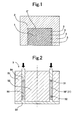
- Fig. 1 is a cross-sectional view for schematically showing an example of a metallic composite material according the present invention.
- Fig. 2 is an explanatory diagram for explaining a production process for a sintered body, which is used for a metallic composite material according to an embodiment, and is an axial cross-sectional view of a forming mold and a green compact.
- Fig. 3 is a cross-sectional view of a sintered body, which is used for a metallic composite material according to an embodiment.
- Fig. 4 is a plan view (upper diagram) of a sintered body, which is used for a metallic composite material according to an embodiment, and a side view (lower diagram) thereof.
- Fig. 5 is an axial cross-sectional view of a metallic composite material according to an embodiment.
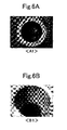
- Fig. 6A is a photograph, a substitute for a diagram for showing the result of a color checking inspection on a metallic composite material according to an embodiment, and is a photograph in which the lower end surface (being equivalent to the position designated with "A1" in Fig. 5) of the metallic composite material was photographed.
- Fig. 6B is a photograph, a substitute for a diagram for showing the result of a color checking inspection on a metallic composite material according to an embodiment, and is a photograph in which the inner surface (being equivalent to the position designated with "B1" in Fig. 5) of the metallic composite material was photographed.
- Fig. 7A is a photograph, a substitute for a diagram for showing the result of a color checking inspection on a metallic composite material according to a comparative example, and is a photograph in which the lower end surface of the metallic composite material was photographed.
- Fig. 7B is a photograph, a substitute for a diagram for showing the result of a color checking inspection on a metallic composite material according to a comparative example, and is a photograph in which the inner surface of the metallic composite material was photographed.
- Fig. 8 is a photomicrograph of a metallic composite material according to an embodiment, and is a photomicrograph of the cross section at the position designated with "C1" in Fig. 5.
- Fig. 9 is a photomicrograph of a metallic composite material according to an embodiment, and is a photomicrograph of the cross section at the position designated with "D1" in Fig. 5.
- Fig. 10 is a graph for showing the Vickers hardness of the respective portions of a metallic composite material according to an embodiment.
- a metallic composite material according to the present invention comprises a composited portion comprising a sintered body being completed by sintering a metallic powder of a first metal, and a second metal infiltrating into the pores of the superficial-layer portion of the sintered body at least; and a parent-material portion comprising the second metal covering a part of the composited potion at least.
- the second metal can be disposed in the superficial-layer portion of the sintered body at least; and it is acceptable that, depending on the parts and configurations in which the metallic composite material is employed, the disposition between the composited portion, which comprises the sintered body and the second metal, and the parent-material portion, which comprises the second metal, can be selected appropriately.
- the composited portion can be positioned so as to be surrounded with the parent-material portion by means of cast wrapping the second metal 2 around the sintered body 1 with a rectangular-parallelepiped configuration other than the bottom surface, for instance, as illustrated in Fig. 1.
- the second metal is present in the pores of the superficial-layer portion thereof (the second metal 2' in Fig. 1, for instance) at least.
- the second metal can be infiltrated into a part or the entirety of the pores, which the sintered body possesses, and can be solidified therein. Therefore, the metallic composite material according to the present invention can desirably be produced by cast wrapping the second metal around the sintered body by means of casting.
- casting methods such as a squeeze casting method and a liquid metal infiltration method, are suitable.
- the sintered body is such that, as far as it has a part such as the dented portion which constitutes a later-described fitting portion, there is not any limitation on the configuration and material quality thereof. It is acceptable that they can be selected appropriately depending on the configurations of the metallic composite material and the parts in which the metallic composite material is employed.
- the metallic powder can be powders which have been used for sintered bodies conventionally, and configurations, whose particle diameter is 1-250 ⁇ m and which are a spherical shape or close to a spherical shape, can be used. These powders can be obtained by means of various atomizing methods and pulverizing methods, and the like, for instance.
- iron-based metallic powders which include iron (Fe) are preferable as the metallic powder of the first metal; for example, it is possible to use various alloy steel powders (SKD-based ones (JIS G4404), SKH-based ones (JIS G4403), and so forth), cast iron powders, carbon steel powders, and so on.
- metallic powders can even be a mixture powder, which includes a lubricant or an additive, and the like.
- it can be various powders of alloying elements other than metals, such as carbon (C) and boron (B), or powders containing them; further, it can even include various compound powders like ceramic powders.
- the sintered body can be those which have such an extent of porosity (the volumetric proportion [%] of the pores that account for the volume of the sintered body: hereinafter, being labeled "Vp") and pore diameter that the second metal can infiltrate into the pores thereof.
- Vp volumetric proportion of the pores that account for the volume of the sintered body
- the second metal is such that there is not any limitation on the type thereof in particular, the present invention demonstrates good effects under the condition of combining metals so that the first metal and the second metal exhibit a great thermal expansion difference.
- the second metal as described above, is such that a part thereof infiltrates into the pores of the sintered body and is solidifies therein, there is not any limitation on the type of the second metal as far as the sintered body does not melt or degrade upon infiltrating a molten metal of the second metal into the sintered body.
- the first metal is an iron-based metal
- the second metal can preferably be an aluminum alloy or a magnesium alloy
- the first metal is a copper-based metal
- the second metal can preferably be an aluminum alloy or a magnesium alloy.
- the metallic composite material according to the present invention can preferably be such that the first metal is an iron-based metal, which includes iron (Fe), and the second metal is a light metal.
- the metallic composite member which is lightweight and is of high strength, is obtainable.
- the light metal it can preferably be aluminum-based metals, such as pure aluminum (Al) and aluminum alloys including Mg, Cu, Zn, Si, Mn, and the like; and it can preferably be magnesium-based metals, such as pure magnesium (Mg) and magnesium alloys including Zn, Al, Zr, Mn, Th, rare-earth elements, and so forth.
- the metallic composite material according to the present invention is equipped with the fitting portion at the interface between the composited portion and the parent-material portion.
- the fitting portion can desirably be constituted of dented portions 3, which are formed in a sintered body 1, and protruded portions, which are formed on the parent-material portion side when a second metal 2 has got into the dented portions 3.
- the second metal exists in the superficial-layer portion of the sintered body 1 at least. Therefore, it is the protruded portions of the second metal 2 as the parent-material portion that fit with the dented portions 3 of the sintered body 1.
- the protruded portions are formed of itself by means of burying the internal spaces of the dented portions with a molten metal of the second metal when the second metal has infiltrated into the pores and additionally the second metal has got into parts where the burn-disappearing member has been burned to disappear or the melt-disappearing member has been melted to disappear.
- the protruded portions and dented portions 3 are such that, not limited to the squared shapes like those in Fig.
- their cross-sectional configurations can be triangles; or can be polygons or key patterns; and moreover their configurations can be solid cylindrical shapes or semi-sphere shapes, which can fit between the sintered body 1 and second metal 2', the composited portion, and the second metal 2, the parent-material portion.
- a dented portion (fitting portion) at locations in the metallic composite material where cracks are likely to occur, that is, in the superficial-layer portion of the sintered body, it is possible to reduce cracks, which occur in metallic composite materials resulting from the thermal expansion difference between the composited portion and the parent-material portion, during services in environments where the heat treatments or temperature changes are fierce.
- the sintered body has a hollow cylindrical configuration, it is acceptable to form a dented portion at one or more locations of either one of an outer peripheral portion, inner peripheral portion, end portion and another end portion thereof.
- the interface between the composited portion and the parent-material portion it is effective when it is formed in a plane, which involves a section being exposed linearly in the surface of the metallic composite material.
- the metallic composite material in Fig. 1 is such that the interface is exposed on the lower side of the diagram. This exposed interface can be observed linearly.
- the fitting portion, along a plane, which involves this exposed section cracks become unlikely to occur.
- the quantity of dented portion there is no limitation on the quantity of dented portion, and it is acceptable to form it in a plurality of pieces as shown in Fig. 1. By means of suitably selecting the forming position and forming quantity of dented portion, it is possible to effectively reduce the occurrence of cracks.
- the dented portions 3 or protruded portions, the fitting portion are not limited to such a construction that they continue as a grooved shape. It is satisfactory that a fitting portion can be disposed discontinuously to such an extent that cracks do not occur; or it is acceptable that it can be disposed partially.
- a dented portion can preferably be formed as a cross-sectionally letter-U shape.
- the fitting portion on the side of the composited portion is a part where the sintered body is formed by sintering the metallic powder together with a melt-disappearing material, which possesses a melting point being the sintering temperature of the metallic powder or less, or a burn-disappearing material, which burns to disappear at the sintering temperature or less; and where the melt-disappearing material has been melted to disappear or the burn-disappearing material has been burned to disappear.
- the fitting portion is formed by getting the second metal into that part upon producing the metallic composite material by carrying out casting.
- the melt-disappearing material or burn-disappearing material is not limited in particular as far as it comprises a material which melts to disappear or burns to disappear at the sintering temperature of the metallic powder or less. Therefore, in addition to metals and resins, it can be paper or wood, and so the material quality thereof does not matter.
- the melting point of the melt-disappearing material can preferably be closer to the sintering temperature.
- the gap between the sintering temperature of the metallic powder and the melting point of the melt-disappearing material is too great, there is a fear that the melt-disappearing material might vaporize to contaminate furnace casings during the sintering step.
- the melt-disappearing material can preferably be copper (Cu).
- Cu copper
- a material quality of the melt-disappearing material can suitably be those including an alloying component element, which forms an alloy with a major component element of the metallic powder (first metal).
- an alloying component element which forms an alloy with a major component element of the metallic powder (first metal).
- the configuration of the melt-disappearing material and burn-disappearing material becomes the same configuration as that of the internal space of a dented portion in the sintered body which is obtainable after sintering, it can suitably be selected depending on the configuration of a dented portion; and accordingly it is possible to use plate-shaped, rod-shaped or linear melt-disappearing materials.
- the sintered body has a hollow cylindrical configuration, it is possible to form a ring-shaped groove in the sintered body by allocating an annular melt-disappearing material so as to be coaxial therewith upon forming the metallic powder.
- the melt-disappearing material is diffused into the surface of the metallic powder, which has been sintered, via the pores, which exist around the melt-disappearing material, by means of sintering.
- the melt-disappearing material after it has melted, hardly closes the pores again when it has solidified, and the like, and accordingly the pores open in the surfaces of parts (dented portions) where it has melted to disappear.
- the metallic composite material according to the present invention since a molten metal of the second metal is likely to infiltrate thereinto through the dented portions as well; moreover, since the second metal, which exists in the pores opening in the surfaces, and the second metal of the protruded portions are disposed one after another successively to be integral, the adhesiveness between the protruded portions on the side of the parent-material portion and the dented portions on the side of the composited portion improves.
- a dented portion of the sintered body is formed by sintering one which is made by molding using a mold having a protruded portion, which corresponds to the dented portion, or by cutting, and the like, the sintered body.
- a mold having a protruded portion which corresponds to the dented portion, or by cutting, and the like
- the sintered body is formed by sintering one which is made by molding using a mold having a protruded portion, which corresponds to the dented portion, or by cutting, and the like, the sintered body.
- the pores which open in the surfaces of the dented portion, are likely to be clogged by means of friction, and so forth.
- Such a sintered body is not preferable, because it is less likely to infiltrate a molten metal into the pores and is poor in terms of the adhesiveness.
- the metallic powder is molded and is then sintered together with a melt-disappearing material or a burn-disappearing material.
- a melt-disappearing material or a burn-disappearing material is placed so as to bring it into contact with an inner surface of the cavity or the end surface of a punch; and then a green compact is formed by pressurizing.
- dented portion for the formation of dented portion, it is possible to use existing facilities (forming molds). Moreover, a dented portion is formed simultaneously with sintering a green compact. Accordingly, without requiring special production steps, it is possible to readily form a dented portion.
- the metallic composite material according to the present invention in compliance with the types of the first metal and second metal, can be used for component parts for various apparatuses.
- the metallic composite material which comprises the sintered body made of an iron-based member, and a light metal, can be suitably used for the front housing or cylinder block, and the like, of compressors. Above all, it is effective to allocate the sintered body at parts, which are likely to be subjected to high pressures.
- the embodiment modes of the metallic composite material according to the present invention have been explained, however, the metallic composite material according to the present invention is not limited to the aforementioned embodiment modes, and can be conducted in various modes to which modifications, improvements, and the like, which one of ordinary skill in the art can carry out, are performed, within a range not departing from the scope of the present invention.
- FIG. 2 is a diagram for explaining a production process for a sintered body, which is used for the present example, and illustrates an apparatus for forming a green compact.
- a forming mold 5 comprises: a hollow-cylinder-configured die 51; a solid-cylinder-configured core 52, which is allocated in the inner space of the die 51 coaxially therewith; a bottom member 53, which is positioned below the die 51 and core 52; and an upper punch 54, which is positioned above the die 51.
- the bottom member 53 is fixed to the bottom portions of the die 51 and core 52.
- the upper punch 54 is formed as a hollow cylindrical configuration, and is allocated at a position slidably in the axial directions (the up/down directions of the drawing) between the die 51 and the core 52.
- a cavity 50 is demarcated by the die 51, the core 52 and the bottom member 53.
- this forming mold 5 it is possible to form a hollow-cylinder-shaped green compact by means of forming the outer peripheral surface by the die 51, the inner peripheral surface by the core 52, the lower end surface by the bottom member 53, and the upper end surface by the upper punch 54, respectively.
- a green compact was formed using the aforementioned apparatus.
- an iron-based metallic powder KIP300A made by KAWASAKI SEITETSU
- an additive which comprised graphite and lithium stearate
- a raw-material powder 1' was obtained by mixing these so as to make a proportion of graphite: 0.7% by mass; and lithium stearate; 1% by mass.
- copper-plate rings whose dimensions differed (outside diameter: ⁇ 96 mm; inside diameter: ⁇ 93 mm; and thickness: 3 mm; hereinafter labeled "copper-plate ring 31 for end surface”; and outside diameter: ⁇ 99.4 mm; inside diameter: ⁇ 94 mm; and thickness: 3 mm; hereinafter labeled "copper-plate ring 32 for side surface”).
- the copper-plate ring 32 for side surface was placed on its surface.
- the outer peripheral surface of the copper-ring plate 32 for side surface was brought into contact with the inner wall surface of the cavity 50 (die 51), as shown in Fig. 2.
- the raw-material powder 1' was further filled.
- the copper-plate ring 31 for end surface was furthermore placed coaxially with the cavity 50.
- the raw-material powder 1' was filled so as to be flush with one of the end surfaces of the copper-plate ring 31 for end surface. That is, the one of the end surfaces of the copper-plate ring 31 for end surface was brought into contact with the end surface of the upper punch 54, upon forming by pressurizing.
- the raw-material powder 1' which was filled in the cavity 50, and the copper-plate rings 31, 32 were subjected to forming by pressurizing, and were thereby turned into a green compact 10'; and was then subjected to mold releasing to remove it from the cavity 50.
- Fig. 3 and Fig. 4 are diagrams for illustrating a sintered body 10, which was obtained by sintering the green compact 10'.
- the sintered body 10 was such that, since the copper-plate rings 31, 32 had been melted to disappear, cross-sectionally letter-U-shaped ring-shaped grooves (end-portion ring-shaped groove 11, and side-portion ring-shaped groove 12) were formed at the upper end portion and outer peripheral portion of the hollow-cylinder-shaped sintered body 10.
- a hollow-cylindrical metallic composite material was manufactured.
- the sintered body 10 was allocated at a predetermined position in the cavity of a squeeze casting mold, and was preheated to 300 °C in an argon atmosphere.
- an aluminum-alloy molten metal (ADC12, and 800-°C molten-metal temperature) was poured into the cavity, and was pressurized with 100-MPa casting pressure.
- ADC12 aluminum-alloy molten metal
- 800-°C molten-metal temperature was poured into the cavity, and was pressurized with 100-MPa casting pressure.
- the section, which was made of the aluminum alloy being formed on the surface of the sintered body 10 (being labeled aluminum alloy 20 in Fig. 5) alone, is referred to as a parent-material portion
- the section, which was made of the sintered body 10 and the aluminum alloy being infiltrated into the porous sections thereof and being solidified therein is referred to as a composited portion.
- the interface, which was exposed in the surfaces of the composite material could be observed linearly in the hollow-cylinder lower surface, which is designated with A1 in Fig. 5, and in the hollow-cylinder inner surface, which is designated with B1 in Fig. 5.
- the end-portion ring-shaped groove 11 and side-portion ring-shaped groove 12; and the protruded portions that fitted with these; the fitting portions, were formed along the planes, which involved these exposed sections.
- a metallic composite material was made ready as a comparative example, metallic composite material which was manufactured in the same manner as the example except that a sintered body, which did not possess any dented portion (which was manufactured without using the copper-plate rings during the sintering), was used.
- a thermal treatment (holding them at 500 °C for 10 hours and thereafter cooling them slowly) was carried out, and then they were inspected for whether cracks occurred or not in the metallic composite materials after the thermal treatment by means of liquid penetrant inspection (color checking inspection).
- the results are shown in Fig. 6A, Fig. 6B, Fig. 7A and Fig. 7B.
- Fig. 6A ⁇ Al> is a photograph in which the lower end surface of the metallic composite material according to the example was photographed, and is equivalent to the position designated with A1 in Fig. 5.
- FIG. 6B ⁇ B1> is a photograph in which the inner surface of the metallic composite material according to the example was photographed, and is equivalent to the position designated with B1 in Fig. 5.
- Fig. 7A ⁇ AO> and Fig. 7B ⁇ B0> relate to the metallic composite material according to the comparative example, they are photographs in which parts, being equivalent to the positions designated with A1 and B1 in Fig. 5, are photographed.
- Fig. 8 is a photograph in which the cross-section of the composited portion, being surrounded with C1 designated in Fig. 5, was observed; and Fig. 9 is a photograph in which the cross-section of the composited portion, being surrounded with D1 designated in Fig. 5, was observed.
- the sections, which were corroded lamellarly, are pearlite (being represented with P).
- the sections, whose color is pale, are ferrite (being represented with F), and the sections, whose color is deep, are the aluminum alloy (being represented with M).
- the sections, which are represented with M occupy 25% of the entire cross section approximately.
- the black sections (being represented with Fc) are sections in which copper solved into iron.
- the sintered body 10 which was made by sintering the iron-based metallic powder, was such that most of it was ferrite; and turned into pearlite partially. And, the aluminum alloy was infiltrated into the porous sections of the sintered body 10, and was solidified therein. Moreover, in the composited portion, which is positioned at D1, most of it was pearlite, and copper solved into iron. And, sections in which the aluminum alloy was solidified in the porous sections of the sintered body 10 could be confirmed. Namely, in the sintered body 10, the copper-plate rings 31, 32 were diffused into iron so that they had melted to disappear during the sintering process, and consequently the pores were not clogged with copper.
- a Vickers hardness measurement was carried out.
- the Vickers hardness measurement was carried out, in the outer peripheral surface (parent-material portion) of the metallic composite material and in the composited portions C1 and D1 which were subjected to the cross-sectional observation, with a measuring load of 10 kgf using a Vickers hardness meter.
- the measured results are shown in Fig. 10.
- the Vickers hardness of the composited portions was greater than the Vickers hardness of the parent-material portion (the section made of the aluminum alloy alone). Moreover, the composited portion (in which copper solved into the sintered body 10), which is positioned at D1, was such that the Vickers hardness was much greater than that of the composited portion, which is positioned at C1. Namely, the metallic composite material according to the present example is good in terms of the strength and wear resistance in the vicinity around the ring-shaped grooves 11, 12.
Landscapes
- Engineering & Computer Science (AREA)
- Manufacturing & Machinery (AREA)
- Mechanical Engineering (AREA)
- Chemical & Material Sciences (AREA)
- Composite Materials (AREA)
- Materials Engineering (AREA)
- Powder Metallurgy (AREA)
Abstract
A metallic composite material according to the present invention is a metallic composite material, which comprises: a composited portion having a sintered body 1 being completed by sintering a metallic powder of a first metal, and a second metal 2' infiltrating into the pores of the superficial-layer portion of the sintered body 1 at least; and a parent-material portion having the second metal 2 covering the composited potion, and is characterized in that the sintered body 1 is completed by sintering the metallic powder together with a melt-disappearing material, which possesses a melting point being the sintering temperature of the metallic powder or less, or a burn-disappearing material, which burns to disappear at the sintering temperature or less; and the metallic composite material is equipped with a fitting portion at the interface between the composited portion and the parent-material portion, fitting portion which is formed by infiltrating the second metal 2' into the pores and additionally getting the second metal 2' into parts 3 where the melt-disappearing material has been melted to disappear or the burn-disappearing material has been burned to disappear. By means of this novel construction, it is possible to suppress the occurrence of cracks and peeling, which occurs in metallic composite material.
In the present invention, the melt-disappearing material can preferably include an alloying component element, which forms an alloy with a major component element of the metallic powder. When major component element is iron and the alloying component element is copper, the strength of the fitting portion improves.
Description
- The present invention relates to a metallic composite material, which comprises metals of different types.
- Since composite materials, which are made by combining different species of constituent raw materials, turn into materials, which have various characteristics being not achievable with conventional materials, by means of changing the types or volumetric proportions of constituent raw materials, they are extremely useful in many fields of industrial materials.
- As one of metal-based composite materials whose parent materials are metals, a metallic composite material is available in which a metal is cast around a sintered body so that the metal is disposed on the superficial portion of the sintered body. In metallic composite materials possessing such a construction, cracks might occur at the interface between both of them (in the surface of sintered body) in environments with violent temperature changes, such as upon cooling after heat treating the composite materials, for instance. This occurrence of cracks results from the thermal expansion difference between sintered body and metal. In particular, although metallic composite materials, which comprise an iron-based sintered body and a light metal such as an aluminum alloy, have been used in various fields, they have a problem that, because the thermal expansion difference between iron-based metal and light metal is great, cracks are likely occur in the surface involving the sintered body.
- Hence, in Japanese Unexamined Patent Publication (KOKAI) Gazette
No. 8-229, 663 - Moreover, in Japanese Unexamined Patent Publication (KOKAI) Gazette
No. 9-206, 915 - However, since these metallic composite materials are such that, since other raw-material powders have been necessary or the number of processing steps has increased and are therefore accompanied by the enlargement of working times and the increment of costs, they cannot be a simple and easy technique.
- The present invention, in view of the aforementioned problematic points, is such that it is an object to provide a metallic composite material, which comprises a novel construction and can suppress the occurrence of cracks and peeling.
- A metallic composite material according to the present invention is a metallic composite material, which comprises: a composited portion comprising a sintered body being completed by sintering a metallic powder of a first metal, and a second metal infiltrating into the pores of the superficial-layer portion of the sintered body at least; and a parent-material portion comprising the second metal covering the composited potion,
the metallic composite material being characterized in that: said sintered body is completed by sintering said metallic powder together with a melt-disappearing material, which possesses a melting point being the sintering temperature of the metallic powder or less, or a burn-disappearing material, which burns to disappear at the sintering temperature or less; and the metallic composite material is equipped with a fitting portion at the interface between said composited portion and said parent-material portion, fitting portion which is formed by infiltrating said second metal into said pores and additionally getting said second metal into parts where the melt-disappearing material has been melted to disappear or the burn-disappearing material has been burned to disappear. - Since the sintered body is one which is completed by sintering the metallic powder, and the melt-disappearing material, which possesses a melting point being the sintering temperature of the metallic powder or less, or the burn-disappearing material, which burns to disappear at the sintering temperature or less, all together, the pores open satisfactorily in parts where the melt-disappearing material has been melted to disappear or the burn-disappearing material has been burned to disappear, that is, in the sintered-body-side (composited-portion-side) surface of the fitting portion. Accordingly, the metallic composite material according to the present invention is good in terms of the infiltratability during the production; and moreover is also good in terms of the adhesion between the composited portion and the parent-material portion at the fitting portion.
- And, by means of the fact that it possesses the fitting portion at the interface between the composited portion and the parent-material portion, it is possible to reduce cracks, which result from the thermal expansion difference between the composited portion and the parent-material portion to occur. On this occasion, it is desirable that said fitting portion can be constituted of a dented portion, which is formed in said sintered body when said melt-disappearing material has been melted to disappear or said burn-disappearing material has been burned to disappear, and a protruded portion, which is formed on the side of the parent-material portion when said second metal has got into the dented portion.
- Moreover, the designating terms such as "first" and "second" are designating terms for distinguishing between the members, and the like, for convenience. Therefore, as far as the first metal and the second metal are metals with different compositions, it is satisfactory.
- In the present invention, said melt-disappearing material can preferably include an alloying component element, which forms an alloy with a major component element of said metallic powder. On this occasion, the maj or component element can preferably be iron, and the alloying component element can preferably be copper. Since copper, the component of the melt-disappearing material, is solved into iron by means of sintering, the strength of the fitting portion improves.
- To put it differently, the metallic composite material according to the present invention is such that it is possible to grasp it as a metallic composite material being a metallic composite material, which comprises: a composited portion comprising a sintered body being completed by sintering a metallic powder of a first metal, and a second metal infiltrating into the pores of the superficial-layer portion of the sintered body at least; and a parent-material portion comprising the second metal covering the composited potion,
the metallic composite material being characterized in that: it further possesses a fitting portion at the interface between said composited portion and said parent-material portion; and an alloy, which comprises a major component element of said metallic powder and an alloying component element forming the alloy with the major component element, is formed at the fitting portion on the side of the composited portion. - As for the fitting portion, the sintered body can preferably be completed by sintering said metallic powder together with a melt-disappearing material, which possesses a melting point being the sintering temperature of the metallic powder or less, or a burn-disappearing material, which burns to disappear at the sintering temperature or less; and the fitting portion can preferably be formed by infiltrating said second metal into said pores and additionally getting said second metal into parts where said melt-disappearing material has been melted to disappear or said burn-disappearing material has been burned to disappear.
- Moreover, it is preferable that said first metal can be an iron-based metal, which includes iron; and that said second metal can be a light metal. By using a light metal, it turns into a metallic composite material, which is lightweight and is of high strength. On this occasion, it is preferable that said light metal can be an aluminum alloy.
- With reference to the following detailed description and the accompanying drawings, the present invention can be understood more profoundly. Hereinafter, the brief description of the drawings is done.
- Fig. 1 is a cross-sectional view for schematically showing an example of a metallic composite material according the present invention.
- Fig. 2 is an explanatory diagram for explaining a production process for a sintered body, which is used for a metallic composite material according to an embodiment, and is an axial cross-sectional view of a forming mold and a green compact.
- Fig. 3 is a cross-sectional view of a sintered body, which is used for a metallic composite material according to an embodiment.
- Fig. 4 is a plan view (upper diagram) of a sintered body, which is used for a metallic composite material according to an embodiment, and a side view (lower diagram) thereof.
- Fig. 5 is an axial cross-sectional view of a metallic composite material according to an embodiment.
- Fig. 6A is a photograph, a substitute for a diagram for showing the result of a color checking inspection on a metallic composite material according to an embodiment, and is a photograph in which the lower end surface (being equivalent to the position designated with "A1" in Fig. 5) of the metallic composite material was photographed. Fig. 6B is a photograph, a substitute for a diagram for showing the result of a color checking inspection on a metallic composite material according to an embodiment, and is a photograph in which the inner surface (being equivalent to the position designated with "B1" in Fig. 5) of the metallic composite material was photographed.
- Fig. 7A is a photograph, a substitute for a diagram for showing the result of a color checking inspection on a metallic composite material according to a comparative example, and is a photograph in which the lower end surface of the metallic composite material was photographed. Fig. 7B is a photograph, a substitute for a diagram for showing the result of a color checking inspection on a metallic composite material according to a comparative example, and is a photograph in which the inner surface of the metallic composite material was photographed.
- Fig. 8 is a photomicrograph of a metallic composite material according to an embodiment, and is a photomicrograph of the cross section at the position designated with "C1" in Fig. 5.
- Fig. 9 is a photomicrograph of a metallic composite material according to an embodiment, and is a photomicrograph of the cross section at the position designated with "D1" in Fig. 5.
- Fig. 10 is a graph for showing the Vickers hardness of the respective portions of a metallic composite material according to an embodiment.
- In order to explain and describe the present invention in more detail, hereinafter, the best mode for carrying out a metallic composite material according to the present invention will be explained using Fig. 1.
- A metallic composite material according to the present invention comprises a composited portion comprising a sintered body being completed by sintering a metallic powder of a first metal, and a second metal infiltrating into the pores of the superficial-layer portion of the sintered body at least; and a parent-material portion comprising the second metal covering a part of the composited potion at least.
- Specifically, in the metallic composite material according to the present invention, it is satisfactory that the second metal can be disposed in the superficial-layer portion of the sintered body at least; and it is acceptable that, depending on the parts and configurations in which the metallic composite material is employed, the disposition between the composited portion, which comprises the sintered body and the second metal, and the parent-material portion, which comprises the second metal, can be selected appropriately. For example, in addition to being a laminated body in which the composited portion and the parent-material portion are laminated to each other in such a state that the second metal infiltrates into one of the surfaces of the sintered body with a flat-plate shape to cover it, it is acceptable that the composited portion can be positioned so as to be surrounded with the parent-material portion by means of cast wrapping the
second metal 2 around thesintered body 1 with a rectangular-parallelepiped configuration other than the bottom surface, for instance, as illustrated in Fig. 1. - Moreover, in the composited portion, the second metal is present in the pores of the superficial-layer portion thereof (the second metal 2' in Fig. 1, for instance) at least. Note that the second metal can be infiltrated into a part or the entirety of the pores, which the sintered body possesses, and can be solidified therein. Therefore, the metallic composite material according to the present invention can desirably be produced by cast wrapping the second metal around the sintered body by means of casting. Especially, casting methods, such as a squeeze casting method and a liquid metal infiltration method, are suitable. In these casting methods, since it is possible to infiltrate the second metal not only into the superficial-layer portion of the sintered body but also into the inside thereof because casting is done while carrying out pressurizing, a metallic composite material, which is close to being nonporous, is obtainable.
- The sintered body is such that, as far as it has a part such as the dented portion which constitutes a later-described fitting portion, there is not any limitation on the configuration and material quality thereof. It is acceptable that they can be selected appropriately depending on the configurations of the metallic composite material and the parts in which the metallic composite material is employed. The metallic powder can be powders which have been used for sintered bodies conventionally, and configurations, whose particle diameter is 1-250 µm and which are a spherical shape or close to a spherical shape, can be used. These powders can be obtained by means of various atomizing methods and pulverizing methods, and the like, for instance. And, although there is not any limitation on the type of the first metal in particular, iron-based metallic powders, which include iron (Fe), are preferable as the metallic powder of the first metal; for example, it is possible to use various alloy steel powders (SKD-based ones (JIS G4404), SKH-based ones (JIS G4403), and so forth), cast iron powders, carbon steel powders, and so on.
- Further, not limited to the cases of being comprised of the aforementioned metallic powders alone, it can even be a mixture powder, which includes a lubricant or an additive, and the like. Moreover, it can be various powders of alloying elements other than metals, such as carbon (C) and boron (B), or powders containing them; further, it can even include various compound powders like ceramic powders.
- Moreover, the sintered body can be those which have such an extent of porosity (the volumetric proportion [%] of the pores that account for the volume of the sintered body: hereinafter, being labeled "Vp") and pore diameter that the second metal can infiltrate into the pores thereof. Note, however, that it is not preferable to use a sintered body which has high porosity or coarse pores, because the strength of the sintered body lowers; moreover because the sintered body might be damaged depending on the method of infiltrating the second metal into the sintered body. Therefore, the sintered body can preferably be such that the volumetric fraction thereof ("Vf" = 100 -"Vp" [%]) is 45% or more, and can further preferably be such that it is 55-85%.
- Although the second metal is such that there is not any limitation on the type thereof in particular, the present invention demonstrates good effects under the condition of combining metals so that the first metal and the second metal exhibit a great thermal expansion difference. Moreover, the second metal, as described above, is such that a part thereof infiltrates into the pores of the sintered body and is solidifies therein, there is not any limitation on the type of the second metal as far as the sintered body does not melt or degrade upon infiltrating a molten metal of the second metal into the sintered body. For example, when it is a metal whose melting point is lower than that of the first metal constituting the sintered body, it is possible to readily produce the metallic composite material. Specifically, when the first metal is an iron-based metal, the second metal can preferably be an aluminum alloy or a magnesium alloy; when the first metal is a copper-based metal, the second metal can preferably be an aluminum alloy or a magnesium alloy.
- Moreover, the metallic composite material according to the present invention can preferably be such that the first metal is an iron-based metal, which includes iron (Fe), and the second metal is a light metal. By means of combining an iron-based metal, which is of high strength, and a light metal, the metallic composite member, which is lightweight and is of high strength, is obtainable. As for the light metal, it can preferably be aluminum-based metals, such as pure aluminum (Al) and aluminum alloys including Mg, Cu, Zn, Si, Mn, and the like; and it can preferably be magnesium-based metals, such as pure magnesium (Mg) and magnesium alloys including Zn, Al, Zr, Mn, Th, rare-earth elements, and so forth.
- And, the metallic composite material according to the present invention is equipped with the fitting portion at the interface between the composited portion and the parent-material portion. For example, as illustrated in Fig. 1, the fitting portion can desirably be constituted of dented
portions 3, which are formed in asintered body 1, and protruded portions, which are formed on the parent-material portion side when asecond metal 2 has got into the dentedportions 3. As described above, the second metal exists in the superficial-layer portion of thesintered body 1 at least. Therefore, it is the protruded portions of thesecond metal 2 as the parent-material portion that fit with the dentedportions 3 of thesintered body 1. When the metallic composite material is produced by the above-described casting methods using a sintered body having dented portions like those aforementioned, the protruded portions are formed of itself by means of burying the internal spaces of the dented portions with a molten metal of the second metal when the second metal has infiltrated into the pores and additionally the second metal has got into parts where the burn-disappearing member has been burned to disappear or the melt-disappearing member has been melted to disappear. Note that it is satisfactory that the protruded portions and dentedportions 3 are such that, not limited to the squared shapes like those in Fig. 1, their cross-sectional configurations can be triangles; or can be polygons or key patterns; and moreover their configurations can be solid cylindrical shapes or semi-sphere shapes, which can fit between thesintered body 1 and second metal 2', the composited portion, and thesecond metal 2, the parent-material portion. - And, by means of forming a dented portion (fitting portion) at locations in the metallic composite material where cracks are likely to occur, that is, in the superficial-layer portion of the sintered body, it is possible to reduce cracks, which occur in metallic composite materials resulting from the thermal expansion difference between the composited portion and the parent-material portion, during services in environments where the heat treatments or temperature changes are fierce. For example, when the sintered body has a hollow cylindrical configuration, it is acceptable to form a dented portion at one or more locations of either one of an outer peripheral portion, inner peripheral portion, end portion and another end portion thereof. Moreover, of the interface between the composited portion and the parent-material portion, it is effective when it is formed in a plane, which involves a section being exposed linearly in the surface of the metallic composite material. For example, the metallic composite material in Fig. 1 is such that the interface is exposed on the lower side of the diagram. This exposed interface can be observed linearly. By forming the dented
portions 3 or protruded portions, the fitting portion, along a plane, which involves this exposed section, cracks become unlikely to occur. Moreover, there is no limitation on the quantity of dented portion, and it is acceptable to form it in a plurality of pieces as shown in Fig. 1. By means of suitably selecting the forming position and forming quantity of dented portion, it is possible to effectively reduce the occurrence of cracks. Moreover, the dentedportions 3 or protruded portions, the fitting portion, are not limited to such a construction that they continue as a grooved shape. It is satisfactory that a fitting portion can be disposed discontinuously to such an extent that cracks do not occur; or it is acceptable that it can be disposed partially. - Moreover, since the superficial area of the sintered body is increased by means of forming dented portions, the thermal conductivity improves. Here, in general, it is said that, in the interface between different materials, heat is likely to transmit in the direction parallel to the interface. Namely, when forming a dented portion, which possesses a perpendicular plane with respect to the interface, the thermal conductivity improves furthermore. Therefore, a dented portion can preferably be formed as a cross-sectionally letter-U shape.
- The fitting portion on the side of the composited portion, such as the dented portions, is a part where the sintered body is formed by sintering the metallic powder together with a melt-disappearing material, which possesses a melting point being the sintering temperature of the metallic powder or less, or a burn-disappearing material, which burns to disappear at the sintering temperature or less; and where the melt-disappearing material has been melted to disappear or the burn-disappearing material has been burned to disappear. As described above, the fitting portion is formed by getting the second metal into that part upon producing the metallic composite material by carrying out casting. The melt-disappearing material or burn-disappearing material is not limited in particular as far as it comprises a material which melts to disappear or burns to disappear at the sintering temperature of the metallic powder or less. Therefore, in addition to metals and resins, it can be paper or wood, and so the material quality thereof does not matter.
- The melting point of the melt-disappearing material can preferably be closer to the sintering temperature. When the gap between the sintering temperature of the metallic powder and the melting point of the melt-disappearing material is too great, there is a fear that the melt-disappearing material might vaporize to contaminate furnace casings during the sintering step. For example, when the metallic powder is an iron-based metallic powder, the melt-disappearing material can preferably be copper (Cu). Specifically, when letting the sintering temperature of the iron-based metallic powder be 1,100 °C, it is acceptable to make copper (melting point: 1,083°C) a material for the melt-disappearing material.
- Moreover, a material quality of the melt-disappearing material can suitably be those including an alloying component element, which forms an alloy with a major component element of the metallic powder (first metal). By means of appropriate combinations, it is possible to intend the improvement of the sintered body's strength, thermal conductivity, sliding property, and the like. For example, when a major component element of the metallic powder is iron (Fe), if the alloying component element is copper (Cu), Cu is solved into Fe so that the sintered body' s strength and thermal conductivity can be improved. Other than this, it is possible to think of the following various combinations of the major component element and alloying component element: when making Fe the major component element, in addition to aforementioned Cu, it is possible to think of carbon (C), chromium (Cr), molybdenum (Mo), nickel (Ni), vanadium (V), and so forth, as the alloying component element.
- Moreover, since the configuration of the melt-disappearing material and burn-disappearing material becomes the same configuration as that of the internal space of a dented portion in the sintered body which is obtainable after sintering, it can suitably be selected depending on the configuration of a dented portion; and accordingly it is possible to use plate-shaped, rod-shaped or linear melt-disappearing materials. Specifically, when the sintered body has a hollow cylindrical configuration, it is possible to form a ring-shaped groove in the sintered body by allocating an annular melt-disappearing material so as to be coaxial therewith upon forming the metallic powder.
- By the way, the melt-disappearing material is diffused into the surface of the metallic powder, which has been sintered, via the pores, which exist around the melt-disappearing material, by means of sintering. Moreover, depending on a material quality of the melt-disappearing material, there might be the case that it has disappeared. That is, the melt-disappearing material, after it has melted, hardly closes the pores again when it has solidified, and the like, and accordingly the pores open in the surfaces of parts (dented portions) where it has melted to disappear. As a result thereof, in the metallic composite material according to the present invention, since a molten metal of the second metal is likely to infiltrate thereinto through the dented portions as well; moreover, since the second metal, which exists in the pores opening in the surfaces, and the second metal of the protruded portions are disposed one after another successively to be integral, the adhesiveness between the protruded portions on the side of the parent-material portion and the dented portions on the side of the composited portion improves.
- Note that it is general that a dented portion of the sintered body is formed by sintering one which is made by molding using a mold having a protruded portion, which corresponds to the dented portion, or by cutting, and the like, the sintered body. However, depending on the configuration and forming position of a dented portion, there might be cases where the construction of the mold gets complicated or the production thereof is difficult. Moreover, when forming a dented portion by cutting, the pores, which open in the surfaces of the dented portion, are likely to be clogged by means of friction, and so forth. Such a sintered body is not preferable, because it is less likely to infiltrate a molten metal into the pores and is poor in terms of the adhesiveness.
- Upon producing the aforementioned sintered body, the metallic powder is molded and is then sintered together with a melt-disappearing material or a burn-disappearing material. For example, using a general forming mold, the metallic powder is filled within a cavity of the forming mold; and additionally a melt-disappearing material or a burn-disappearing material is placed so as to bring it into contact with an inner surface of the cavity or the end surface of a punch; and then a green compact is formed by pressurizing. By sintering the obtained green compact, a sintered body, which has a dented portion formed in the superficial portion when the melt-disappearing material has melted to disappear or the burn-disappearing material has burned to disappear, is obtainable.
- As aforementioned, for the formation of dented portion, it is possible to use existing facilities (forming molds). Moreover, a dented portion is formed simultaneously with sintering a green compact. Accordingly, without requiring special production steps, it is possible to readily form a dented portion.
- The metallic composite material according to the present invention, in compliance with the types of the first metal and second metal, can be used for component parts for various apparatuses. Especially, the metallic composite material, which comprises the sintered body made of an iron-based member, and a light metal, can be suitably used for the front housing or cylinder block, and the like, of compressors. Above all, it is effective to allocate the sintered body at parts, which are likely to be subjected to high pressures.
- So far, the embodiment modes of the metallic composite material according to the present invention have been explained, however, the metallic composite material according to the present invention is not limited to the aforementioned embodiment modes, and can be conducted in various modes to which modifications, improvements, and the like, which one of ordinary skill in the art can carry out, are performed, within a range not departing from the scope of the present invention.
- Based on the aforementioned embodiment modes, metallic composite materials were prepared. Hereinafter, examples of the metallic composite material according to the present invention will be explained using Fig. 2-Fig. 10.
- [Manufacture of Sintered Body Having Dented Portions]
- Fig. 2 is a diagram for explaining a production process for a sintered body, which is used for the present example, and illustrates an apparatus for forming a green compact. A forming
mold 5 comprises: a hollow-cylinder-configureddie 51; a solid-cylinder-configuredcore 52, which is allocated in the inner space of thedie 51 coaxially therewith; abottom member 53, which is positioned below thedie 51 andcore 52; and anupper punch 54, which is positioned above thedie 51. Thebottom member 53 is fixed to the bottom portions of thedie 51 andcore 52. Theupper punch 54 is formed as a hollow cylindrical configuration, and is allocated at a position slidably in the axial directions (the up/down directions of the drawing) between the die 51 and thecore 52. And, acavity 50 is demarcated by thedie 51, thecore 52 and thebottom member 53. Note that, in accordance with this formingmold 5, it is possible to form a hollow-cylinder-shaped green compact by means of forming the outer peripheral surface by thedie 51, the inner peripheral surface by thecore 52, the lower end surface by thebottom member 53, and the upper end surface by theupper punch 54, respectively. - A green compact was formed using the aforementioned apparatus. First of all, an iron-based metallic powder (KIP300A made by KAWASAKI SEITETSU), and an additive, which comprised graphite and lithium stearate, were prepared. A raw-material powder 1' was obtained by mixing these so as to make a proportion of graphite: 0.7% by mass; and lithium stearate; 1% by mass. Moreover, two copper-plate rings were made ready, copper-plate rings whose dimensions differed (outside diameter: φ 96 mm; inside diameter: φ 93 mm; and thickness: 3 mm; hereinafter labeled "copper-
plate ring 31 for end surface"; and outside diameter: φ 99.4 mm; inside diameter: φ 94 mm; and thickness: 3 mm; hereinafter labeled "copper-plate ring 32 for side surface"). - And, a predetermined amount of the raw-material powder 1' was filled into the lower portion of the
cavity 50. After smoothing the surface of the filled raw-material powder 1' so as to be the 10-mm position from thebottom member 53, the copper-plate ring 32 for side surface was placed on its surface. On this occasion, the outer peripheral surface of the copper-ring plate 32 for side surface was brought into contact with the inner wall surface of the cavity 50 (die 51), as shown in Fig. 2. On the raw-material powder 1', which had been filled in advance, and on the copper-plate ring 32 for side surface, the raw-material powder 1' was further filled. After smoothing the surface of the filled raw-material powder 1' the copper-plate ring 31 for end surface was furthermore placed coaxially with thecavity 50. And, the raw-material powder 1' was filled so as to be flush with one of the end surfaces of the copper-plate ring 31 for end surface. That is, the one of the end surfaces of the copper-plate ring 31 for end surface was brought into contact with the end surface of theupper punch 54, upon forming by pressurizing. - Thereafter, by descending the
upper punch 54, the raw-material powder 1', which was filled in thecavity 50, and the copper-plate rings 31, 32 were subjected to forming by pressurizing, and were thereby turned into a green compact 10'; and was then subjected to mold releasing to remove it from thecavity 50. The obtained green compact 10' was such that the outside diameter was φ100 mm; the inside diameter was φ 89 mm; the height was 60 mm; and the volumetric fraction was Vf = 75 [%]. - Next, the green compact 10' was sintered at 1,150 °C for 1 hour in vacuum. Fig. 3 and Fig. 4 are diagrams for illustrating a
sintered body 10, which was obtained by sintering the green compact 10'. Thesintered body 10 was such that, since the copper-plate rings 31, 32 had been melted to disappear, cross-sectionally letter-U-shaped ring-shaped grooves (end-portion ring-shapedgroove 11, and side-portion ring-shaped groove 12) were formed at the upper end portion and outer peripheral portion of the hollow-cylinder-shapedsintered body 10. - [Manufacture of Metallic Composite Member]
- Using the
sintered body 10 obtained in the aforementioned process, a hollow-cylindrical metallic composite material was manufactured. Thesintered body 10 was allocated at a predetermined position in the cavity of a squeeze casting mold, and was preheated to 300 °C in an argon atmosphere. In such a state, an aluminum-alloy molten metal (ADC12, and 800-°C molten-metal temperature) was poured into the cavity, and was pressurized with 100-MPa casting pressure. Thus, a metallic composite material, which possessed the aluminum alloy on the surface and the porous sections of thesintered body 10, was obtained. The axial cross-sectional diagram of the obtained metallic composite material is illustrated in Fig. 5. In the end-portion ring-shapedgroove 11 and side-portion ring-shapedgroove 12 of thesintered body 10, protruded portions, which were made of the aluminum alloy, were formed by means of casting, and the grooves and protruded portions fitted to each other. Moreover, at the locations designated with theend portion 16 andside portion 17 in Fig. 3 and Fig. 4, it was possible to visually observe the fact that copper was diffused in widths of 10-20 mm approximately over the entire circumference of thesintered body 10. - Note that the section, which was made of the aluminum alloy being formed on the surface of the sintered body 10 (being labeled
aluminum alloy 20 in Fig. 5) alone, is referred to as a parent-material portion, and the section, which was made of thesintered body 10 and the aluminum alloy being infiltrated into the porous sections thereof and being solidified therein (being labeled aluminum alloy 20' therein), is referred to as a composited portion. Of this interface between the parent-material portion and the composited portion, the interface, which was exposed in the surfaces of the composite material, could be observed linearly in the hollow-cylinder lower surface, which is designated with A1 in Fig. 5, and in the hollow-cylinder inner surface, which is designated with B1 in Fig. 5. The end-portion ring-shapedgroove 11 and side-portion ring-shapedgroove 12; and the protruded portions that fitted with these; the fitting portions, were formed along the planes, which involved these exposed sections. - Moreover, a metallic composite material was made ready as a comparative example, metallic composite material which was manufactured in the same manner as the example except that a sintered body, which did not possess any dented portion (which was manufactured without using the copper-plate rings during the sintering), was used.
- [Evaluation]
- [Existence and Nonexistence of Cracks]
- Regarding the metallic composite materials according to the example and comparative example, a thermal treatment (holding them at 500 °C for 10 hours and thereafter cooling them slowly) was carried out, and then they were inspected for whether cracks occurred or not in the metallic composite materials after the thermal treatment by means of liquid penetrant inspection (color checking inspection). The results are shown in Fig. 6A, Fig. 6B, Fig. 7A and Fig. 7B. Note that Fig. 6A <Al> is a photograph in which the lower end surface of the metallic composite material according to the example was photographed, and is equivalent to the position designated with A1 in Fig. 5. Fig. 6B <B1> is a photograph in which the inner surface of the metallic composite material according to the example was photographed, and is equivalent to the position designated with B1 in Fig. 5. Moreover, although Fig. 7A <AO> and Fig. 7B <B0> relate to the metallic composite material according to the comparative example, they are photographs in which parts, being equivalent to the positions designated with A1 and B1 in Fig. 5, are photographed.
- In the metallic composite material according to the example, the occurrence of cracks was hardly appreciated. However, in the metallic composite material according to the comparative example in which no dented portion was formed, cracks occurred in a part of the inner surface and in the entire circumference of the lower end surface (see the arrowheaded sections in Fig. 7A and Fig. 7B). Namely, by means of the dented portions formed in the sintered body, the occurrence of cracks, which would have occurred in the outer peripheral surface and upper end surface of the sintered body, was suppressed.
- Note that, in regard to the inner peripheral surface which is the blind spot in <B1> and <B0>, the situation was the same as described above.
- [Cross-sectional Surface Observation]
- Regarding the metallic composite material according to the example, the cross-sectional structure was observed by means of a metallurgical microscope. The cross-sectional observation was carried out with respect to the composited portion of the metallic composite material, and the cut cross-section was observed after etching it with nital etchant (3% by weight) for 30 seconds. The results are shown in Fig. 8 and Fig. 9. Note that Fig. 8 is a photograph in which the cross-section of the composited portion, being surrounded with C1 designated in Fig. 5, was observed; and Fig. 9 is a photograph in which the cross-section of the composited portion, being surrounded with D1 designated in Fig. 5, was observed.
- In Fig. 8 and Fig. 9, the sections, which were corroded lamellarly, are pearlite (being represented with P). In Fig. 8, the sections, whose color is pale, are ferrite (being represented with F), and the sections, whose color is deep, are the aluminum alloy (being represented with M). In Fig. 8, the sections, which are represented with M, occupy 25% of the entire cross section approximately. Moreover, in Fig. 9, the black sections (being represented with Fc) are sections in which copper solved into iron.
- In the composited portion, which is positioned at C1, the
sintered body 10, which was made by sintering the iron-based metallic powder, was such that most of it was ferrite; and turned into pearlite partially. And, the aluminum alloy was infiltrated into the porous sections of thesintered body 10, and was solidified therein. Moreover, in the composited portion, which is positioned at D1, most of it was pearlite, and copper solved into iron. And, sections in which the aluminum alloy was solidified in the porous sections of thesintered body 10 could be confirmed. Namely, in thesintered body 10, the copper-plate rings 31, 32 were diffused into iron so that they had melted to disappear during the sintering process, and consequently the pores were not clogged with copper. - [Vickers Hardness Measurement]
- Regarding the metallic composite material according to the example, a Vickers hardness measurement was carried out. The Vickers hardness measurement was carried out, in the outer peripheral surface (parent-material portion) of the metallic composite material and in the composited portions C1 and D1 which were subjected to the cross-sectional observation, with a measuring load of 10 kgf using a Vickers hardness meter. The measured results are shown in Fig. 10.
- The Vickers hardness of the composited portions was greater than the Vickers hardness of the parent-material portion (the section made of the aluminum alloy alone). Moreover, the composited portion (in which copper solved into the sintered body 10), which is positioned at D1, was such that the Vickers hardness was much greater than that of the composited portion, which is positioned at C1. Namely, the metallic composite material according to the present example is good in terms of the strength and wear resistance in the vicinity around the ring-shaped
grooves
Claims (11)
- A metallic composite material being a metallic composite material, which comprises: a composited portion having a sintered body being completed by sintering a metallic powder of a first metal, and a second metal infiltrating into the pores of the superficial-layer portion of the sintered body at least; and a parent-material portion having the second metal covering the composited potion,
the metallic composite material being characterized in that: said sintered body is completed by sintering said metallic powder together with a melt-disappearing material, which possesses a melting point being the sintering temperature of the metallic powder or less, or a burn-disappearing material, which burns to disappear at the sintering temperature or less; and the metallic composite material is equipped with a fitting portion at the interface between said composited portion and said parent-material portion, fitting portion which is formed by infiltrating said second metal into said pores and additionally getting said second metal into parts where the melt-disappearing material has been melted to disappear or the burn-disappearing material has been burned to disappear. - The metallic composite material set forth in claim 1, wherein said fitting portion is constituted of a dented portion, which is formed in said sintered body when said melt-disappearing material has been melted to disappear or said burn-disappearing material has been burned to disappear, and a protruded portion, which is formed on the side of the parent-material portion when said second metal has got into the dented portion.
- The metallic composite material set forth in claim 1, wherein said melt-disappearing material includes an alloying component element, which forms an alloy with a major component element of said metallic powder, and the alloy is formed at parts of said sintered body, parts where the melt-disappearing material has been melted to disappear.
- The metallic composite material set forth in claim 3, wherein said major component element is iron, and said alloying component element is copper.
- The metallic composite material set forth in claim 1, wherein said first metal is an iron-based metal, which includes iron, and said second metal is a light metal.
- The metallic composite material set forth in claim 5, wherein said light metal is an aluminum alloy.
- The metallic composite material set forth in claim 2, wherein said sintered body is a hollow cylindrical configuration, and has said dented portion at either one of an outer peripheral portion, inner peripheral portion, end portion and another end portion thereof at least.
- The metallic composite material set forth in claim 7, wherein said dented portion is an annular ring-shaped groove, which is positioned coaxially with said sintered body being formed as a hollow cylindrical configuration.
- The metallic composite material set forth in claim 8, wherein said ring-shaped groove is a cross-sectionally letter-U shape.
- The metallic composite material set forth in claim 1, wherein said fitting portion is formed in a plane of the interface between said composited portion and said parent-material portion, plane which involves a section being exposed linearly in a surface thereof.
- A metallic composite material being a metallic composite material, which comprises: a composited portion having a sintered body being completed by sintering a metallic powder of a first metal, and a second metal infiltrating into the pores of the superficial-layer portion of the sintered body at least; and a parent-material portion having the second metal covering the composited potion,
the metallic composite material being characterized in that: it further possesses a fitting portion at the interface between said composited portion and said parent-material portion; and an alloy, which comprises a major component element of said metallic powder and an alloying component element forming the alloy with the major component element, is formed at the fitting portion on the side of the composited portion.
Applications Claiming Priority (2)
| Application Number | Priority Date | Filing Date | Title |
|---|---|---|---|
| JP2004350316A JP2006161069A (en) | 2004-12-02 | 2004-12-02 | Metal composite material |
| PCT/JP2005/021184 WO2006059494A1 (en) | 2004-12-02 | 2005-11-11 | Metal composite material |
Publications (1)
| Publication Number | Publication Date |
|---|---|
| EP1829634A1 true EP1829634A1 (en) | 2007-09-05 |
Family
ID=36564929
Family Applications (1)
| Application Number | Title | Priority Date | Filing Date |
|---|---|---|---|
| EP05803955A Withdrawn EP1829634A1 (en) | 2004-12-02 | 2005-11-11 | Metal composite material |
Country Status (4)
| Country | Link |
|---|---|
| US (1) | US20080261067A1 (en) |
| EP (1) | EP1829634A1 (en) |
| JP (1) | JP2006161069A (en) |
| WO (1) | WO2006059494A1 (en) |
Families Citing this family (1)
| Publication number | Priority date | Publication date | Assignee | Title |
|---|---|---|---|---|
| JP2024542397A (en) * | 2021-11-22 | 2024-11-15 | モット・コーポレーション | Porous flow restrictor and method of manufacture thereof |
Family Cites Families (4)
| Publication number | Priority date | Publication date | Assignee | Title |
|---|---|---|---|---|
| JPS56147329U (en) * | 1980-04-07 | 1981-11-06 | ||
| JPS6049521B2 (en) * | 1982-04-06 | 1985-11-02 | 森川産業株式会社 | Manufacturing method of cylinder liner for internal combustion engine |
| JP3800510B2 (en) * | 2001-11-22 | 2006-07-26 | 株式会社豊田自動織機 | Powder compact, method for producing the same, and method for producing a porous sintered body |
| JP2003171703A (en) * | 2001-12-03 | 2003-06-20 | Toyota Industries Corp | Porous sintered compact and its manufacturing method |
-
2004
- 2004-12-02 JP JP2004350316A patent/JP2006161069A/en active Pending
-
2005
- 2005-11-11 EP EP05803955A patent/EP1829634A1/en not_active Withdrawn
- 2005-11-11 US US11/792,117 patent/US20080261067A1/en not_active Abandoned
- 2005-11-11 WO PCT/JP2005/021184 patent/WO2006059494A1/en not_active Ceased
Non-Patent Citations (1)
| Title |
|---|
| See references of WO2006059494A1 * |
Also Published As
| Publication number | Publication date |
|---|---|
| US20080261067A1 (en) | 2008-10-23 |
| JP2006161069A (en) | 2006-06-22 |
| WO2006059494A1 (en) | 2006-06-08 |
Similar Documents
| Publication | Publication Date | Title |
|---|---|---|
| EP0143330B1 (en) | Reinforced pistons | |
| US5299620A (en) | Metal casting surface modification by powder impregnation | |
| US3786552A (en) | Method of manufacturing a composite bimetallic sleeve for a die-casting machine | |
| US8926896B2 (en) | Method of compacting a first powder material and a second powder material | |
| JPH08504886A (en) | Sintered article | |
| US20050153156A1 (en) | Composited cast member, iron-based porous substance for composited cast members, and pressure casing processes for producing the same, constituent member of compressors provided with composited cast members and the compressors | |
| US5341866A (en) | Method for the incorporation of a component into a piston | |
| US20100116240A1 (en) | Multi-piece thin walled powder metal cylinder liners | |
| JP3850357B2 (en) | Porous metal structure | |
| JP2010274315A (en) | Valve seat for cast-in insert of light metal alloy | |
| US20080261067A1 (en) | Metallic Composite Material | |
| JP5525995B2 (en) | Sintered member for casting, method for producing the same, and method for casting light alloy composite member using the sintered member for casting | |
| US5989729A (en) | Wear resistant metal composite | |
| US20090277415A1 (en) | Cylinder crankcase for a motor vehicle | |
| JP2010133029A (en) | Metal composite material and method for producing the same | |
| JP2005163145A (en) | Composite casting, iron based porous body for casting, and their production method | |
| JP6563494B2 (en) | Wear-resistant ring composite with excellent thermal conductivity | |
| JP2021504580A (en) | Powder metal alloy composition of sintered powder metal inserts for aluminum castings | |
| JP4524591B2 (en) | Composite material and manufacturing method thereof | |
| JP4223817B2 (en) | Valve seat for light metal alloy casting | |
| Capus | Advances in Powder Metallurgy Processing. | |
| JP6867255B2 (en) | Complex with low coefficient of thermal expansion and high adhesion | |
| JP2003171703A (en) | Porous sintered compact and its manufacturing method | |
| JP2003073755A (en) | Porous metal-sintered compact for strengthening light alloy member, and manufacturing method therefor | |
| JP4638138B2 (en) | PRESSURE CONTAINER, MANUFACTURING METHOD THEREOF, COMPRESSOR AND ITS COMPONENT |
Legal Events
| Date | Code | Title | Description |
|---|---|---|---|
| PUAI | Public reference made under article 153(3) epc to a published international application that has entered the european phase |
Free format text: ORIGINAL CODE: 0009012 |
|
| 17P | Request for examination filed |
Effective date: 20070530 |
|
| AK | Designated contracting states |
Kind code of ref document: A1 Designated state(s): DE FR |
|
| DAX | Request for extension of the european patent (deleted) | ||
| RBV | Designated contracting states (corrected) |
Designated state(s): DE FR |
|
| STAA | Information on the status of an ep patent application or granted ep patent |
Free format text: STATUS: THE APPLICATION HAS BEEN WITHDRAWN |
|
| 18W | Application withdrawn |
Effective date: 20121109 |