EP1828752B1 - A method and apparatus for analysing a dynamic sample - Google Patents
A method and apparatus for analysing a dynamic sample Download PDFInfo
- Publication number
- EP1828752B1 EP1828752B1 EP05820422A EP05820422A EP1828752B1 EP 1828752 B1 EP1828752 B1 EP 1828752B1 EP 05820422 A EP05820422 A EP 05820422A EP 05820422 A EP05820422 A EP 05820422A EP 1828752 B1 EP1828752 B1 EP 1828752B1
- Authority
- EP
- European Patent Office
- Prior art keywords
- region
- sample
- component
- light beam
- labels
- Prior art date
- Legal status (The legal status is an assumption and is not a legal conclusion. Google has not performed a legal analysis and makes no representation as to the accuracy of the status listed.)
- Expired - Lifetime
Links
Images

Classifications
-
- G—PHYSICS
- G01—MEASURING; TESTING
- G01N—INVESTIGATING OR ANALYSING MATERIALS BY DETERMINING THEIR CHEMICAL OR PHYSICAL PROPERTIES
- G01N21/00—Investigating or analysing materials by the use of optical means, i.e. using sub-millimetre waves, infrared, visible or ultraviolet light
- G01N21/62—Systems in which the material investigated is excited whereby it emits light or causes a change in wavelength of the incident light
- G01N21/63—Systems in which the material investigated is excited whereby it emits light or causes a change in wavelength of the incident light optically excited
- G01N21/64—Fluorescence; Phosphorescence
- G01N21/645—Specially adapted constructive features of fluorimeters
- G01N21/6456—Spatial resolved fluorescence measurements; Imaging
-
- G—PHYSICS
- G01—MEASURING; TESTING
- G01N—INVESTIGATING OR ANALYSING MATERIALS BY DETERMINING THEIR CHEMICAL OR PHYSICAL PROPERTIES
- G01N15/00—Investigating characteristics of particles; Investigating permeability, pore-volume or surface-area of porous materials
- G01N15/10—Investigating individual particles
- G01N15/14—Optical investigation techniques, e.g. flow cytometry
-
- G—PHYSICS
- G01—MEASURING; TESTING
- G01N—INVESTIGATING OR ANALYSING MATERIALS BY DETERMINING THEIR CHEMICAL OR PHYSICAL PROPERTIES
- G01N15/00—Investigating characteristics of particles; Investigating permeability, pore-volume or surface-area of porous materials
-
- G—PHYSICS
- G01—MEASURING; TESTING
- G01N—INVESTIGATING OR ANALYSING MATERIALS BY DETERMINING THEIR CHEMICAL OR PHYSICAL PROPERTIES
- G01N21/00—Investigating or analysing materials by the use of optical means, i.e. using sub-millimetre waves, infrared, visible or ultraviolet light
- G01N21/62—Systems in which the material investigated is excited whereby it emits light or causes a change in wavelength of the incident light
- G01N21/63—Systems in which the material investigated is excited whereby it emits light or causes a change in wavelength of the incident light optically excited
- G01N21/64—Fluorescence; Phosphorescence
- G01N21/6428—Measuring fluorescence of fluorescent products of reactions or of fluorochrome labelled reactive substances, e.g. measuring quenching effects, using measuring "optrodes"
Definitions
- the present invention relates to a method and apparatus for analysing a sample of biological material which includes moving components.
- a conventional approach to tracking moving components in a sample is to determine changes relative to the background in order to identify regions which may be mobile components of interest.
- the components of interest may be tagged by fluorescent labels or probes, making the task of distinguishing them from the background relatively straightforward.
- Fluorescent molecules employed as labels typically have a specific excitation spectrum, being more strongly excited at some wavelengths and less strongly excited at others. They also have a specific emission spectrum, emitting more intensely at some wavelengths, and less intensely at others.
- the excitation and emission spectra may range from the ultraviolet to the infrared.
- a wide range of fluorescent probes have been developed from chemical molecules, such as Rhodamine and Fluoroscein. Further fluorescent probes have been developed from molecules found in luminescent organisms, for example the Aequorea Jellyfish which has provided the Green Fluorescent Protein (GFP), and various corals providing DsRed and HcRed. These have been termed AFPs (Aequorea Fluorescent Proteins) and are described for example in J. Zhang, et al, Nature Reviews: Molecular Cell Biol., Vol 3, Dec 2002, pp906-918 ; Y.A. Labas, Proc. Natl. Acad. Sci., 2002, Vol 99, pp4256-4261 ; and M.V. Matz, Bioassay, Vol 24, pp953-959 .
- the fluorescent probes may be associated with specific molecules of interest (DNA, RNA, proteins, carbohydrates, antibodies, etc). Alternatively they may be made to be sensitive to certain characteristics (ionic concentration, pH, voltage potential, temperature, the presence of a specific enzyme, the presence of specific enzyme substrates, force), altering their fluorescent properties according to these characteristics. These labels may be introduced into cells by passing through the cell membrane or by injection. Alternatively they may be formed internally as part of the normal functioning of the cell, in the case of the genetically encoded probes such as the AFPs.
- a fluorescence microscope ( Figures. 1 ) is fitted with an excitation light source which is capable of exciting one or more fluorescent probes at specific wavebands.
- the microscope is also fitted with suitable optical filters so that the light emitted from the probes may be observed at other wavebands. Examining the spatial and temporal distribution of light emitted provides information on the structure and dynamics of the sample.
- the fluorescence microscope is often fitted with an image acquisition system, comprising a light sensitive detector (sensitive from the ultraviolet to the infrared) such as a CCD camera or a combination of a scanner and a photomultiplier tube, and recording means such as a video recorder or computer system with a memory device, so that dynamic behaviour of the sample may be captured and analysed offline.
- a light sensitive detector sensitive from the ultraviolet to the infrared
- CCD camera a combination of a scanner and a photomultiplier tube
- recording means such as a video recorder or computer system with a memory device
- the system may employ a focus drive mechanism for altering the position of the imaging focus plane, thus allowing volumetric (XYZ) and volumetric time series (XYZT) data to be acquired.
- volumetric (XYZ) and volumetric time series (XYZT) data may be acquired.
- the microscope may also be fitted with additional apparatus to control the temperature, gas content and flow, introduce liquids, etc.
- an additional activating light beam may be provided (in many cases based on the excitation light source).
- the activating light beam may be directed to portions of the sample containing labels in such a manner that the intense light from this beam bleaches the label and reduces its fluorescence.
- information can be obtained on mechanisms of interaction and exchange of various labelled components (for example, as described in AxelRod, Biophys. J., 1977, Vol 18, pp129-131 ; and Phair et al, Nature, 2000, Vol 404, pp604-609 ).
- Moving components may often be distinguishable by their size, shape or trajectory, for example. However, this can be problematic if the components concerned are very similar in shape and size, or vary considerably in shape and size over time, or have unpredictable trajectories.
- US 5215883 discloses rapid measurement of the electrophoretic mobility of fluorescently labelled DNA fragments in gels using crossed laser beams to produce a static photobleached interference pattern on the gel and then measuring movements of unbleached fluorescently labelled DNA fragments through the photobleached pattern on electrophoretic separation by low intensity illumination in the same interference pattern, producing a periodic interaction between the photobleached pattern and the fluorescent pattern.
- GFP green fluorescent protein
- Nichols et al describe the use of photobleaching to monitor the transfer of labelled components to and from the Golgi complex of a cell. Initially, all fluorescence outside the Golgi region is eliminated by photobleaching.
- the present invention is directed at a method of analysing a sample of biological material including moving components tagged with respective fluorescent labels, the method comprising the steps of identifying a specific labelled component to be monitored, and irradiating with a light beam at least one region of the sample which substantially surrounds said specific component so as to photobleach labels in the region such that they are distinguishable from the label associated with said specific component.
- the method includes the steps of monitoring the at least one irradiated region, and triggering a further irradiation step in response to detection of additional labelled components entering the at least one region. This serves to assist the tracking of said specific component. Further irradiation may ensure that said specific component continues to be distinguishable from other adjacent labelled components in a dynamic sample.
- the imaging apparatus is configured to monitor the one or more irradiated regions and trigger a further irradiation in response to detection of additional labelled components entering the one or more regions.
- irradiation may be controlled so as to only occur when necessary, minimising the amount of radiation incident on the sample.
- the light beam may irradiate two or more regions which in combination substantially surround said specific component.
- the one or more regions may substantially surround said specific component in two or three dimensions. They may define a complete or substantially complete geometric shape, such as an annulus (in two dimensions) or a hollow sphere (in three dimensions) for example.
- the one or more regions define an enclosed area or volume which is elongate. In particular, it may be elongate in the direction of travel of said specific component.
- the invention is further directed at apparatus for analysing a sample including moving components tagged with respective fluorescent labels, the apparatus including means for irradiating at least one region of the sample with a light beam so as to photobleach labels in the region, a support for holding the sample, and control means adapted to move the light beam and the sample support relative to each other, so that said movement causes the irradiating means to irradiate with the light beam at least one region of the sample which substantially surrounds the location of a specific labelled component so as to photobleach labels in the region, such that they are distinguishable from the label associated with said specific component.
- the apparatus includes means for monitoring the at least one irradiated region and triggering a further irradiation in response to detection of additional labelled components entering the at least one region.
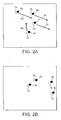
- Figure 2A shows four components 2a to 2d in a sample, each tagged with a respective fluorescent label, 4a to 4d. The direction of travel of each component is indicated by a respective arrow, 6a to 6d.
- Figure 2B shows the same view as 2A, after a period of time has elapsed. It can be seen that an observer following component 2d may risk confusing it with component 2a which passes close to it.
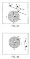
- an annular region 8 surrounding the component of interest 2d is irradiated with an energy beam, as shown in Figure 3A .
- an energy beam may be used, having an intensity in the annular region 8 sufficient to bleach any fluorescent label on which it is incident.
- the more bleached region is monitored, and bleaching only applied if any object is observed to be entering the region. This has the advantage of minimizing the amount of light allowed to reach the sample.
- the desired result is achieved by optically modifying (bleaching) the neighbouring components but to leave the component of interest unmodified.
- the bleached region may be of a doughnut shape, that is, a ring of bleached material.
- a central, less bleached area of unmodified material is surrounded by a more bleached region which is optically modified and the region beyond the more bleached area which is also unmodified.
- the central, less bleached area is preferably somewhat larger than the component of interest, to take into account uncertainty in the position and motion of the component of interest.
- the more bleached area is preferably large enough to optically modify all the components likely to be confused with the component of interest, but small enough to permit the instrument to deliver a light dose sufficient to optically modify the neighbouring components without causing damage to the sample (cell).
- the more bleached area may for example be scanned in a linear (raster) format, or any vector or dot pattern.
- the beam itself may be formed into the desired shape, such as an annular shape, for example.
- the shape of the irradiated region may be fixed, or may be modified at each time point, based on the information extracted from the image in the view, by instruction from the user, from some other source, or a combination of the three. In this manner neighbouring and potentially interfering components will be bleached and removed from consideration, making continued tracking of the component of interest possible.
- a more bleached area substantially encloses a central, less bleached area, which includes the component of interest.
- the central less bleached area is disc-shaped, and the more bleached area is a ring around the less bleached area.
- the central less bleached area may be a square, rectangle, arc segment, oblong, or other regular or irregular enclosed shape.
- the more bleached area may be a square, rectangle, or other regular or irregular enclosed shape, the whole sample or the whole imaging window.
- the component of interest may be a cell, part of a cell, or an assembly of cells in one or more fields of view, for example.
- More than one less bleached area may be defined, and more than one more bleached region may be formed.
- the bleached region may be defined based on the trajectory, route or expected trajectory of the component of interest, thus creating an exclusion zone around the path of the component of interest.
- the region may be based upon the structure of the sample, and may be defined by the shape of the structure, for example, a cell wall, organelle, tubule, and so on.
- the time profile of the scanning of the irradiating beam may be non-linear, for example, defining a spiral, with the margin of the irradiated region close to the less bleached area being scanned more slowly and thus receiving an increased light dose.
- a hexagonal scan may be used, which may be easier to implement.
- the system may facilitate a simultaneous bleach-and-view process, by the appropriate use of wavelengths and light filtering components.
- the system may operate by alternating view-then-bleach steps.
- the bleaching light and the viewing light may be of different wavelengths and/or different power levels.
- Components in a sample may be labelled with one or more fluorescent probes, such as GFP for example, by small molecules such as Fluoroscein, or photoswitching proteins such as KFP1 (described in D.M. Chudakov et al, J. Biol. Chem., 2003, Vol. 278(9), pp. 7215-7219 ), Kaede (see R. Ando, H. Hama, M. Yamamoto-Hino, H. Mizuno and A. Miyawaki, An optical marker based on the UV-induced green-to-red photoconversion of a fluorescent protein, PNAS, October 1, 2002, vol. 99, no. 20, pp. 12651-12656 ), and PA-GFP (see J. Lippincott-Schwartz et al, Nature Supp. Imaging in Cell Biol., Sept 2003, S7-S14 ).
- the sample may be scanned in the Z-direction (that is, perpendicular to the plane of view) to acquire volumetric information.
- the more bleached region may extend into a different Z-plane than the less bleached region.
- the more bleached region may be defined above and/or below the component of interest. In particular, this could be used to extend an annular shape to create a weakly enclosed sphere.
- the region above/below could be formed by modifying the optical path of the bleaching beam and/or using an off-axis path, and/or modulating the beam.
- the more bleached region could be part of a sphere. This bleached region could be monitored and bleached according to the actual or predicted trajectory of the component, or other components.
- Irradiation of a sample at different positions along the Z-axis could be carried out using the well-established 2-photon (or multi-photon) mechanism.
- the fluorescent molecules at this location receive 2 photons almost simultaneously, providing the equivalent energy of 1 photon of half the wavelength, thus bleaching the molecules. Molecules above and below this plane are much less likely to receive two photons so are not affected.
- This beam may be steered around the particle of interest by moving the sample and/or beam to create the substantially surrounding region.
Landscapes
- Health & Medical Sciences (AREA)
- Chemical & Material Sciences (AREA)
- Immunology (AREA)
- Physics & Mathematics (AREA)
- Life Sciences & Earth Sciences (AREA)
- Analytical Chemistry (AREA)
- Biochemistry (AREA)
- General Health & Medical Sciences (AREA)
- General Physics & Mathematics (AREA)
- Pathology (AREA)
- Dispersion Chemistry (AREA)
- Nuclear Medicine, Radiotherapy & Molecular Imaging (AREA)
- Chemical Kinetics & Catalysis (AREA)
- Optics & Photonics (AREA)
- Investigating, Analyzing Materials By Fluorescence Or Luminescence (AREA)
Description
- The present invention relates to a method and apparatus for analysing a sample of biological material which includes moving components.
- A conventional approach to tracking moving components in a sample is to determine changes relative to the background in order to identify regions which may be mobile components of interest. In fluorescence microscopy, the components of interest may be tagged by fluorescent labels or probes, making the task of distinguishing them from the background relatively straightforward.
- Fluorescent molecules employed as labels typically have a specific excitation spectrum, being more strongly excited at some wavelengths and less strongly excited at others. They also have a specific emission spectrum, emitting more intensely at some wavelengths, and less intensely at others. The excitation and emission spectra may range from the ultraviolet to the infrared.
- A wide range of fluorescent probes have been developed from chemical molecules, such as Rhodamine and Fluoroscein. Further fluorescent probes have been developed from molecules found in luminescent organisms, for example the Aequorea Jellyfish which has provided the Green Fluorescent Protein (GFP), and various corals providing DsRed and HcRed. These have been termed AFPs (Aequorea Fluorescent Proteins) and are described for example in J. Zhang, et al, Nature Reviews: Molecular Cell Biol., Vol 3, Dec 2002, pp906-918; Y.A. Labas, Proc. Natl. Acad. Sci., 2002, Vol 99, pp4256-4261; and M.V. Matz, Bioassay, Vol 24, pp953-959.
- The fluorescent probes may be associated with specific molecules of interest (DNA, RNA, proteins, carbohydrates, antibodies, etc). Alternatively they may be made to be sensitive to certain characteristics (ionic concentration, pH, voltage potential, temperature, the presence of a specific enzyme, the presence of specific enzyme substrates, force), altering their fluorescent properties according to these characteristics. These labels may be introduced into cells by passing through the cell membrane or by injection. Alternatively they may be formed internally as part of the normal functioning of the cell, in the case of the genetically encoded probes such as the AFPs.
- In a known apparatus for imaging samples including fluorescent labels, a fluorescence microscope (
Figures. 1 ) is fitted with an excitation light source which is capable of exciting one or more fluorescent probes at specific wavebands. The microscope is also fitted with suitable optical filters so that the light emitted from the probes may be observed at other wavebands. Examining the spatial and temporal distribution of light emitted provides information on the structure and dynamics of the sample. - The use of multiple labels provides information on the coincident localisation of labelled components, revealing, for example, the organization of the cytoskeleton of a cell. The fluorescence microscope is often fitted with an image acquisition system, comprising a light sensitive detector (sensitive from the ultraviolet to the infrared) such as a CCD camera or a combination of a scanner and a photomultiplier tube, and recording means such as a video recorder or computer system with a memory device, so that dynamic behaviour of the sample may be captured and analysed offline.
- The system may employ a focus drive mechanism for altering the position of the imaging focus plane, thus allowing volumetric (XYZ) and volumetric time series (XYZT) data to be acquired. By selecting suitable excitation and/or emission wavebands and/or selecting suitable optical filter sets, volumetric multi-wavelength (XYWZ) and volumetric multi-wavelength time series (XYWZT) data may be acquired.
- The microscope may also be fitted with additional apparatus to control the temperature, gas content and flow, introduce liquids, etc.
- In order to gain a deeper understanding of the dynamic processes in a sample such as a living cell, an additional activating light beam may be provided (in many cases based on the excitation light source). The activating light beam may be directed to portions of the sample containing labels in such a manner that the intense light from this beam bleaches the label and reduces its fluorescence. By observing the subsequent development of fluorescence in this region, and elsewhere in the sample, information can be obtained on mechanisms of interaction and exchange of various labelled components (for example, as described in AxelRod, Biophys. J., 1977, Vol 18, pp129-131; and Phair et al, Nature, 2000, Vol 404, pp604-609).
- Methods and apparatus for analysis of samples including fluorescent labels are disclosed in
W02006/024819 . - Moving components may often be distinguishable by their size, shape or trajectory, for example. However, this can be problematic if the components concerned are very similar in shape and size, or vary considerably in shape and size over time, or have unpredictable trajectories.
- Existing approaches to addressing this problem include locating candidate particles and estimating the matches between frames. Examples are described in J.L. Barron, Fleet, D.J., and Beauchemin, S. (1994) Performance of optical flow techniques, International Journal of Computer Vision, 12(1):43-77; Nagel, H.-H. 1977, Analysing Sequences of TV-Frames: System Design Considerations, In Proc. Intern. Joint Conference on Artificial Intelligence, Cambridge, MA, 626; Nagel, H.-H. 2000, Image Sequence Evaluation: 30 Years and Still Going Strong, In Proc. 15th Intern. Conf. Pattern Recognition, A. Sanfeliu, J.J. Villanueva, M. Vanrell, R. Alqu'ezar, J.-O. Eklundh, and Y. Aloimonos (Eds.), Vol. 1, 149-158. Los Alamitos, CA: IEEE Computer Society; M. Isard and A. Blake, Condensation - conditional density propagation for visual tracking, International Journal of Computer Vision 29(1), pp. 5-28, 1998; D. Comaniciu, V. Ramesh, and P. Meer, Kernel-Based Object Tracking, IEEE PAMI, vol. 25, no. 5, May 2003; Raffel M., Willert C., Kompenhans J (1998) Particle Image Velocimetry. Springer, Berlin; Stanislas, M., Kompenhans, J., Westerweel, J., Particle Image Velocimetry - Progress towards Industrial Application, Kluwer Academic Publishers, 2000.
- Separate bleach and imaging scanning techniques are described in
UK Patent Specification No. 2369739 - Hell et al in Current Opinion in Neurobiology 2004 14:599-609 discloses stimulated emission depletion (STED) microscopy for high resolution imaging of fluorescently stained static samples.
-
US 5215883 discloses rapid measurement of the electrophoretic mobility of fluorescently labelled DNA fragments in gels using crossed laser beams to produce a static photobleached interference pattern on the gel and then measuring movements of unbleached fluorescently labelled DNA fragments through the photobleached pattern on electrophoretic separation by low intensity illumination in the same interference pattern, producing a periodic interaction between the photobleached pattern and the fluorescent pattern. - Hirschfield in The Journal of Histochemistry and Cytochemistry Vol. 27 No. 1 p.96-101, 1979 discloses photochemical bleaching of fluorescent dyes to time discriminate between diverse fluorescent molecules.
- Roberts et al in Journal of Fluorescence Vol. 13, No. 6, November 2003, p513-517, discusses photobleaching of background fluorescence.
- Kutbitschek et al in Biophysical Journal Vol. 78, April 2000, p2170-2179, discloses tracking of green fluorescent protein (GFP) molecole by fluorescence microscopy.
- In "Rapid Cycling of Lipid Raft Markers between the Cell Surface and Golgi Complex", Nichols et al describe the use of photobleaching to monitor the transfer of labelled components to and from the Golgi complex of a cell. Initially, all fluorescence outside the Golgi region is eliminated by photobleaching.
- The present invention is directed at a method of analysing a sample of biological material including moving components tagged with respective fluorescent labels, the method comprising the steps of identifying a specific labelled component to be monitored, and irradiating with a light beam at least one region of the sample which substantially surrounds said specific component so as to photobleach labels in the region such that they are distinguishable from the label associated with said specific component.
- According to the invention, the method includes the steps of monitoring the at least one irradiated region, and triggering a further irradiation step in response to detection of additional labelled components entering the at least one region. This serves to assist the tracking of said specific component. Further irradiation may ensure that said specific component continues to be distinguishable from other adjacent labelled components in a dynamic sample.
- Advantageously the imaging apparatus is configured to monitor the one or more irradiated regions and trigger a further irradiation in response to detection of additional labelled components entering the one or more regions. In this way, irradiation may be controlled so as to only occur when necessary, minimising the amount of radiation incident on the sample.
- In embodiments of the invention, the light beam may irradiate two or more regions which in combination substantially surround said specific component.
- The one or more regions may substantially surround said specific component in two or three dimensions. They may define a complete or substantially complete geometric shape, such as an annulus (in two dimensions) or a hollow sphere (in three dimensions) for example.
- In a preferred embodiment, the one or more regions define an enclosed area or volume which is elongate. In particular, it may be elongate in the direction of travel of said specific component.
- The invention is further directed at apparatus for analysing a sample including moving components tagged with respective fluorescent labels, the apparatus including means for irradiating at least one region of the sample with a light beam so as to photobleach labels in the region, a support for holding the sample, and control means adapted to move the light beam and the sample support relative to each other, so that said movement causes the irradiating means to irradiate with the light beam at least one region of the sample which substantially surrounds the location of a specific labelled component so as to photobleach labels in the region, such that they are distinguishable from the label associated with said specific component.
- According to the invention, the apparatus includes means for monitoring the at least one irradiated region and triggering a further irradiation in response to detection of additional labelled components entering the at least one region.
- Prior art and embodiments of the invention will now be described by way of example and with reference to the accompanying schematic drawings, wherein:
-
Figure 1 shows a block diagram of a known apparatus for investigating biological samples; -
Figures 2A and 2B show images of part of a sample at two points in time; and -
Figures 3A and 3B show images of part of a sample at two points in time and bleaching of a selected region according to an embodiment of the invention. -
Figure 2A shows fourcomponents 2a to 2d in a sample, each tagged with a respective fluorescent label, 4a to 4d. The direction of travel of each component is indicated by a respective arrow, 6a to 6d. -
Figure 2B shows the same view as 2A, after a period of time has elapsed. It can be seen that anobserver following component 2d may risk confusing it withcomponent 2a which passes close to it. - To address this issue, according to an embodiment of the invention, an
annular region 8 surrounding the component ofinterest 2d is irradiated with an energy beam, as shown inFigure 3A . For example, a light beam may be used, having an intensity in theannular region 8 sufficient to bleach any fluorescent label on which it is incident. - The configurations of particles at two instances of time shown in
Figures 3A and 3B correspond to those ofFigures 2A and 2B . However, it can be seen that inFigure 3B ,component 2a and its associatedlabel 4a fall within theregion 8 surrounding the component ofinterest 2d, and itslabel 4d. Irradiation ofregion 8 inFigure 3B bleacheslabel 4a, making thelabel 4d optically distinguishable therefrom. - According to the invention, the more bleached region is monitored, and bleaching only applied if any object is observed to be entering the region. This has the advantage of minimizing the amount of light allowed to reach the sample.
- Thus the desired result is achieved by optically modifying (bleaching) the neighbouring components but to leave the component of interest unmodified.
- The bleached region may be of a doughnut shape, that is, a ring of bleached material. A central, less bleached area of unmodified material, is surrounded by a more bleached region which is optically modified and the region beyond the more bleached area which is also unmodified. The central, less bleached area is preferably somewhat larger than the component of interest, to take into account uncertainty in the position and motion of the component of interest.
- The more bleached area is preferably large enough to optically modify all the components likely to be confused with the component of interest, but small enough to permit the instrument to deliver a light dose sufficient to optically modify the neighbouring components without causing damage to the sample (cell).
- The more bleached area may for example be scanned in a linear (raster) format, or any vector or dot pattern. Alternatively, the beam itself may be formed into the desired shape, such as an annular shape, for example.
- Formation of a laser beam having an annular (or "doughnut") cross-section is described for example in K. S. Youngworth and T. G. Brown, "Focusing of high numerical aperture cylindrical-vector beams," Opt. Express 7, 77-87 (2000); and Gao, C., "New Donut Mode for Optical Tweezers and Spanners, "SPIE 4244, pgs86-89, 2000.
- The shape of the irradiated region may be fixed, or may be modified at each time point, based on the information extracted from the image in the view, by instruction from the user, from some other source, or a combination of the three. In this manner neighbouring and potentially interfering components will be bleached and removed from consideration, making continued tracking of the component of interest possible.
- Typically, a more bleached area substantially encloses a central, less bleached area, which includes the component of interest. In a preferred embodiment, the central less bleached area is disc-shaped, and the more bleached area is a ring around the less bleached area.
- Alternatively, the central less bleached area may be a square, rectangle, arc segment, oblong, or other regular or irregular enclosed shape. Furthermore, the more bleached area may be a square, rectangle, or other regular or irregular enclosed shape, the whole sample or the whole imaging window.
- The component of interest may be a cell, part of a cell, or an assembly of cells in one or more fields of view, for example.
- More than one less bleached area may be defined, and more than one more bleached region may be formed.
- The bleached region may be defined based on the trajectory, route or expected trajectory of the component of interest, thus creating an exclusion zone around the path of the component of interest. In some cases, the region may be based upon the structure of the sample, and may be defined by the shape of the structure, for example, a cell wall, organelle, tubule, and so on.
- The time profile of the scanning of the irradiating beam may be non-linear, for example, defining a spiral, with the margin of the irradiated region close to the less bleached area being scanned more slowly and thus receiving an increased light dose. Alternatively a hexagonal scan may be used, which may be easier to implement.
- The system may facilitate a simultaneous bleach-and-view process, by the appropriate use of wavelengths and light filtering components. Alternatively, the system may operate by alternating view-then-bleach steps.
- The bleaching light and the viewing light may be of different wavelengths and/or different power levels.
- Components in a sample may be labelled with one or more fluorescent probes, such as GFP for example, by small molecules such as Fluoroscein, or photoswitching proteins such as KFP1 (described in D.M. Chudakov et al, J. Biol. Chem., 2003, Vol. 278(9), pp. 7215-7219), Kaede (see R. Ando, H. Hama, M. Yamamoto-Hino, H. Mizuno and A. Miyawaki, An optical marker based on the UV-induced green-to-red photoconversion of a fluorescent protein, PNAS, October 1, 2002, vol. 99, no. 20, pp. 12651-12656), and PA-GFP (see J. Lippincott-Schwartz et al, Nature Supp. Imaging in Cell Biol., Sept 2003, S7-S14).
- The sample may be scanned in the Z-direction (that is, perpendicular to the plane of view) to acquire volumetric information. Furthermore, the more bleached region may extend into a different Z-plane than the less bleached region. The more bleached region may be defined above and/or below the component of interest. In particular, this could be used to extend an annular shape to create a weakly enclosed sphere. The region above/below could be formed by modifying the optical path of the bleaching beam and/or using an off-axis path, and/or modulating the beam.
- The more bleached region could be part of a sphere. This bleached region could be monitored and bleached according to the actual or predicted trajectory of the component, or other components.
- Irradiation of a sample at different positions along the Z-axis could be carried out using the well-established 2-photon (or multi-photon) mechanism. This requires a high power pulsed laser of longer wavelength (typically 800-1000nm) which emits very short intense pulses which are focussed at specific Z planes. The fluorescent molecules at this location receive 2 photons almost simultaneously, providing the equivalent energy of 1 photon of half the wavelength, thus bleaching the molecules. Molecules above and below this plane are much less likely to receive two photons so are not affected. This beam may be steered around the particle of interest by moving the sample and/or beam to create the substantially surrounding region.
Claims (9)
- A method of analysing a sample of biological material including moving components (2a,2b,2c,2d) tagged with respective fluorescent labels (4a,4b,4c,4d), wherein the method comprises the steps of:identifying a specific labelled component (2d) to be monitored; andirradiating with a light beam at least one region (8) of the sample which substantially surrounds said specific component so as to photobleach labels in the region such that they are distinguishable from the label associated with said specific component,and the method is characterized by the steps of:monitoring the at least one irradiated region; andtriggering a further irradiation step in response to detection of additional labelled components (2a) entering the at least one region.
- A method of claim 1, wherein the at least one region (8) is defined based on the trajectory, path or expected trajectory of the component to be monitored.
- A method of claim 1 or claim 2 wherein the light beam may irradiate two or more regions (8) which in combination substantially surround said specific component (2d).
- A method of any preceding claim wherein the at least one-region (8) may substantially surround said specific component (2d) in two or three dimensions.
- A method of any preceding claim wherein the at least one region (8) defines an enclosed area or volume which is elongate.
- A method of claim 5 wherein the enclosed area or volume is elongate in the direction of travel of said specific component (2d).
- A method of any preceding claim, further comprising moving the light beam and sample relative to each other.
- Apparatus for analysing a sample of biological material including moving components (2a,2b,2c,2d) tagged with respective fluorescent labels (4a,4b,4c,4d), the apparatus including:means for irradiating at least one region (8) of the sample with a light beam so as to photobleach labels in the region;a support for holding the sample; andcontrol means adapted to move the light beam and the sample support relative to each other, so that said movement causes the irradiating means to irradiate with the light beam at least one region of the sample which substantially surrounds the location of a specific labelled component so as to photobleach labels in the region, such that they are distinguishable from the label associated with said specific component,characterised in that the apparatus includes means for monitoring the at least one irradiated region and triggering a further irradiation in response to detection of additional labelled components (2a) entering the at least one region.
- Apparatus of claim 8, wherein the at least one region (8) is defined based on the trajectory, path or expected trajectory of the component to be monitored.
Applications Claiming Priority (3)
| Application Number | Priority Date | Filing Date | Title |
|---|---|---|---|
| GBGB0428044.2A GB0428044D0 (en) | 2004-12-22 | 2004-12-22 | A method and apparatus for analysing a dynamic sample |
| GB0515845A GB2421569B (en) | 2004-12-22 | 2005-08-02 | A method and apparatus for analysing a dynamic sample |
| PCT/GB2005/004954 WO2006067426A1 (en) | 2004-12-22 | 2005-12-21 | A method and apparatus for analysing a dynamic sample |
Publications (2)
| Publication Number | Publication Date |
|---|---|
| EP1828752A1 EP1828752A1 (en) | 2007-09-05 |
| EP1828752B1 true EP1828752B1 (en) | 2012-09-12 |
Family
ID=35950987
Family Applications (1)
| Application Number | Title | Priority Date | Filing Date |
|---|---|---|---|
| EP05820422A Expired - Lifetime EP1828752B1 (en) | 2004-12-22 | 2005-12-21 | A method and apparatus for analysing a dynamic sample |
Country Status (5)
| Country | Link |
|---|---|
| EP (1) | EP1828752B1 (en) |
| KR (1) | KR101234143B1 (en) |
| AU (1) | AU2005317850B2 (en) |
| CA (1) | CA2585608C (en) |
| WO (1) | WO2006067426A1 (en) |
Family Cites Families (7)
| Publication number | Priority date | Publication date | Assignee | Title |
|---|---|---|---|---|
| US646234A (en) * | 1899-12-30 | 1900-03-27 | Paar Double Cushion Horse Shoe Company | Rubber-cushion horseshoe. |
| JPS59134808A (en) * | 1983-01-22 | 1984-08-02 | Hitachi Ltd | On-load tap-changing transformer |
| US5215883A (en) * | 1990-07-09 | 1993-06-01 | The Research Foundation | Electrophoretic mobility of fluorophore labeled particles in gels by fluorophore movement after photobleaching |
| DE19829981C2 (en) * | 1998-07-04 | 2002-10-17 | Zeiss Carl Jena Gmbh | Method and arrangement for confocal microscopy |
| PT1146480E (en) * | 2000-04-06 | 2004-01-30 | European Molecular Biology Lab Embl | COMPUTER CONTROLLED MICROSCOPE |
| DE10050529B4 (en) | 2000-10-11 | 2016-06-09 | Leica Microsystems Cms Gmbh | Method for beam control in a scanning microscope, arrangement for beam control in a scanning microscope and scanning microscope |
| JP4480976B2 (en) | 2003-01-28 | 2010-06-16 | オリンパス株式会社 | Scanning optical microscope apparatus, control method therefor, and program |
-
2005
- 2005-12-21 AU AU2005317850A patent/AU2005317850B2/en not_active Expired
- 2005-12-21 CA CA2585608A patent/CA2585608C/en not_active Expired - Lifetime
- 2005-12-21 EP EP05820422A patent/EP1828752B1/en not_active Expired - Lifetime
- 2005-12-21 KR KR1020077016558A patent/KR101234143B1/en not_active Expired - Fee Related
- 2005-12-21 WO PCT/GB2005/004954 patent/WO2006067426A1/en not_active Ceased
Non-Patent Citations (2)
| Title |
|---|
| KUBITSCHECK U. ET AL: "Imaging and Tracking of Single GFP Molecules in Solution", BIOPHYSICAL JOURNAL, NEW YORK, US, US, vol. 78, 1 April 2000 (2000-04-01), pages 2170 - 2179, XP002985267, ISSN: 0006-3495 * |
| NICHOLS BENJAMIN J. ET AL: "Rapid cycling of lipid raft markers between the cell surface and Golgi complex", JOURNAL OF CELL BIOLOGY, vol. 153, no. 3, 30 April 2001 (2001-04-30), pages 529 - 541, ISSN: 0021-9525 * |
Also Published As
| Publication number | Publication date |
|---|---|
| KR101234143B1 (en) | 2013-02-22 |
| KR20070092289A (en) | 2007-09-12 |
| WO2006067426A1 (en) | 2006-06-29 |
| EP1828752A1 (en) | 2007-09-05 |
| CA2585608A1 (en) | 2006-06-29 |
| AU2005317850A1 (en) | 2006-06-29 |
| AU2005317850B2 (en) | 2011-05-12 |
| CA2585608C (en) | 2014-05-13 |
Similar Documents
| Publication | Publication Date | Title |
|---|---|---|
| Gould et al. | Imaging biological structures with fluorescence photoactivation localization microscopy | |
| EP2325684B1 (en) | Microscope device and fluorescent observing method using same | |
| Nienhaus et al. | Where do we stand with super-resolution optical microscopy? | |
| Fernández-Suárez et al. | Fluorescent probes for super-resolution imaging in living cells | |
| Lippincott-Schwartz et al. | Monitoring the dynamics and mobility of membrane proteins tagged with green fluorescent protein | |
| US20070196815A1 (en) | Positive Selection Procedure for Optically Directed Selection of Cells | |
| Hess et al. | Ultrahigh resolution imaging of biomolecules by fluorescence photoactivation localization microscopy | |
| EP2375240B1 (en) | A method of analysing a sample and apparatus therefor | |
| US7521696B2 (en) | Method and apparatus for analyzing a dynamic sample | |
| EP1784633B1 (en) | A method of analysing a sample and apparatus therefor | |
| CA2585608C (en) | A method and apparatus for analysing a dynamic sample | |
| WO2006061640A2 (en) | Method of, and apparatus and computer software for imaging biological objects | |
| Gould et al. | Nanoscale biological fluorescence imaging: Breaking the diffraction barrier | |
| JP2008096155A (en) | Fine particle detector | |
| Zou et al. | The advantage of MINFLUX nanoscopy in single molecular tracking within living cells. | |
| WO2025228413A1 (en) | Optically detected magnetic resonance with light-sheet microscopy | |
| Chu et al. | Multiplexed single-molecule fluorescence measurements enabled by multi-parameter spectroscopic detection of nanostructured FRET labels | |
| Frost et al. | Live-cell PALM of intracellular proteins in neurons | |
| JULLIEN | Spatiotemporal Light Modulation for Optical Sectioning, Diffusion Measurement and Parallelized Experiments with a Dual-DMD Microscope | |
| Gudheti et al. | Fluorescence Photoactivation Localization Microscopy | |
| Mancebo et al. | Calibrated, spatially informed illumination for precise conventional fluorescence and PALM imaging applications | |
| Ross | John R. Allen and Michael W. Davidson |
Legal Events
| Date | Code | Title | Description |
|---|---|---|---|
| PUAI | Public reference made under article 153(3) epc to a published international application that has entered the european phase |
Free format text: ORIGINAL CODE: 0009012 |
|
| 17P | Request for examination filed |
Effective date: 20070526 |
|
| AK | Designated contracting states |
Kind code of ref document: A1 Designated state(s): AT BE BG CH CY CZ DE DK EE ES FI FR GB GR HU IE IS IT LI LT LU LV MC NL PL PT RO SE SI SK TR |
|
| DAX | Request for extension of the european patent (deleted) | ||
| 17Q | First examination report despatched |
Effective date: 20080619 |
|
| GRAP | Despatch of communication of intention to grant a patent |
Free format text: ORIGINAL CODE: EPIDOSNIGR1 |
|
| RIN1 | Information on inventor provided before grant (corrected) |
Inventor name: LADHA, SHAB,PERKINELMER LIFE SCIENCES Inventor name: BUSH, STEVE,PERKINELMER LIFE SCIENCES Inventor name: HOULT,ROBERTPERKINELMER LIFE SCIENCES Inventor name: FITCH, ALISTAIR,PERKINELMER LIFE SCIENCES Inventor name: BLACKMORE, COLIN,PERKINELMER LIFE SCIENCES Inventor name: COURTNEY,PATRICKPERKINELMER LIFE SCIENCES |
|
| GRAJ | Information related to disapproval of communication of intention to grant by the applicant or resumption of examination proceedings by the epo deleted |
Free format text: ORIGINAL CODE: EPIDOSDIGR1 |
|
| GRAP | Despatch of communication of intention to grant a patent |
Free format text: ORIGINAL CODE: EPIDOSNIGR1 |
|
| GRAS | Grant fee paid |
Free format text: ORIGINAL CODE: EPIDOSNIGR3 |
|
| GRAA | (expected) grant |
Free format text: ORIGINAL CODE: 0009210 |
|
| AK | Designated contracting states |
Kind code of ref document: B1 Designated state(s): AT BE BG CH CY CZ DE DK EE ES FI FR GB GR HU IE IS IT LI LT LU LV MC NL PL PT RO SE SI SK TR |
|
| REG | Reference to a national code |
Ref country code: GB Ref legal event code: FG4D |
|
| REG | Reference to a national code |
Ref country code: CH Ref legal event code: EP |
|
| REG | Reference to a national code |
Ref country code: AT Ref legal event code: REF Ref document number: 575307 Country of ref document: AT Kind code of ref document: T Effective date: 20120915 |
|
| REG | Reference to a national code |
Ref country code: IE Ref legal event code: FG4D |
|
| REG | Reference to a national code |
Ref country code: DE Ref legal event code: R096 Ref document number: 602005036136 Country of ref document: DE Effective date: 20121108 |
|
| PG25 | Lapsed in a contracting state [announced via postgrant information from national office to epo] |
Ref country code: FI Free format text: LAPSE BECAUSE OF FAILURE TO SUBMIT A TRANSLATION OF THE DESCRIPTION OR TO PAY THE FEE WITHIN THE PRESCRIBED TIME-LIMIT Effective date: 20120912 Ref country code: CY Free format text: LAPSE BECAUSE OF FAILURE TO SUBMIT A TRANSLATION OF THE DESCRIPTION OR TO PAY THE FEE WITHIN THE PRESCRIBED TIME-LIMIT Effective date: 20120912 Ref country code: LT Free format text: LAPSE BECAUSE OF FAILURE TO SUBMIT A TRANSLATION OF THE DESCRIPTION OR TO PAY THE FEE WITHIN THE PRESCRIBED TIME-LIMIT Effective date: 20120912 |
|
| REG | Reference to a national code |
Ref country code: NL Ref legal event code: VDEP Effective date: 20120912 |
|
| REG | Reference to a national code |
Ref country code: AT Ref legal event code: MK05 Ref document number: 575307 Country of ref document: AT Kind code of ref document: T Effective date: 20120912 |
|
| REG | Reference to a national code |
Ref country code: LT Ref legal event code: MG4D Effective date: 20120912 |
|
| PG25 | Lapsed in a contracting state [announced via postgrant information from national office to epo] |
Ref country code: SE Free format text: LAPSE BECAUSE OF FAILURE TO SUBMIT A TRANSLATION OF THE DESCRIPTION OR TO PAY THE FEE WITHIN THE PRESCRIBED TIME-LIMIT Effective date: 20120912 Ref country code: SI Free format text: LAPSE BECAUSE OF FAILURE TO SUBMIT A TRANSLATION OF THE DESCRIPTION OR TO PAY THE FEE WITHIN THE PRESCRIBED TIME-LIMIT Effective date: 20120912 Ref country code: GR Free format text: LAPSE BECAUSE OF FAILURE TO SUBMIT A TRANSLATION OF THE DESCRIPTION OR TO PAY THE FEE WITHIN THE PRESCRIBED TIME-LIMIT Effective date: 20121213 Ref country code: LV Free format text: LAPSE BECAUSE OF FAILURE TO SUBMIT A TRANSLATION OF THE DESCRIPTION OR TO PAY THE FEE WITHIN THE PRESCRIBED TIME-LIMIT Effective date: 20120912 |
|
| PG25 | Lapsed in a contracting state [announced via postgrant information from national office to epo] |
Ref country code: EE Free format text: LAPSE BECAUSE OF FAILURE TO SUBMIT A TRANSLATION OF THE DESCRIPTION OR TO PAY THE FEE WITHIN THE PRESCRIBED TIME-LIMIT Effective date: 20120912 Ref country code: ES Free format text: LAPSE BECAUSE OF FAILURE TO SUBMIT A TRANSLATION OF THE DESCRIPTION OR TO PAY THE FEE WITHIN THE PRESCRIBED TIME-LIMIT Effective date: 20121223 Ref country code: CZ Free format text: LAPSE BECAUSE OF FAILURE TO SUBMIT A TRANSLATION OF THE DESCRIPTION OR TO PAY THE FEE WITHIN THE PRESCRIBED TIME-LIMIT Effective date: 20120912 Ref country code: BE Free format text: LAPSE BECAUSE OF FAILURE TO SUBMIT A TRANSLATION OF THE DESCRIPTION OR TO PAY THE FEE WITHIN THE PRESCRIBED TIME-LIMIT Effective date: 20120912 Ref country code: RO Free format text: LAPSE BECAUSE OF FAILURE TO SUBMIT A TRANSLATION OF THE DESCRIPTION OR TO PAY THE FEE WITHIN THE PRESCRIBED TIME-LIMIT Effective date: 20120912 Ref country code: NL Free format text: LAPSE BECAUSE OF FAILURE TO SUBMIT A TRANSLATION OF THE DESCRIPTION OR TO PAY THE FEE WITHIN THE PRESCRIBED TIME-LIMIT Effective date: 20120912 Ref country code: IS Free format text: LAPSE BECAUSE OF FAILURE TO SUBMIT A TRANSLATION OF THE DESCRIPTION OR TO PAY THE FEE WITHIN THE PRESCRIBED TIME-LIMIT Effective date: 20130112 |
|
| PG25 | Lapsed in a contracting state [announced via postgrant information from national office to epo] |
Ref country code: PT Free format text: LAPSE BECAUSE OF FAILURE TO SUBMIT A TRANSLATION OF THE DESCRIPTION OR TO PAY THE FEE WITHIN THE PRESCRIBED TIME-LIMIT Effective date: 20130114 Ref country code: PL Free format text: LAPSE BECAUSE OF FAILURE TO SUBMIT A TRANSLATION OF THE DESCRIPTION OR TO PAY THE FEE WITHIN THE PRESCRIBED TIME-LIMIT Effective date: 20120912 Ref country code: SK Free format text: LAPSE BECAUSE OF FAILURE TO SUBMIT A TRANSLATION OF THE DESCRIPTION OR TO PAY THE FEE WITHIN THE PRESCRIBED TIME-LIMIT Effective date: 20120912 |
|
| PG25 | Lapsed in a contracting state [announced via postgrant information from national office to epo] |
Ref country code: AT Free format text: LAPSE BECAUSE OF FAILURE TO SUBMIT A TRANSLATION OF THE DESCRIPTION OR TO PAY THE FEE WITHIN THE PRESCRIBED TIME-LIMIT Effective date: 20120912 |
|
| PLBE | No opposition filed within time limit |
Free format text: ORIGINAL CODE: 0009261 |
|
| STAA | Information on the status of an ep patent application or granted ep patent |
Free format text: STATUS: NO OPPOSITION FILED WITHIN TIME LIMIT |
|
| PG25 | Lapsed in a contracting state [announced via postgrant information from national office to epo] |
Ref country code: DK Free format text: LAPSE BECAUSE OF FAILURE TO SUBMIT A TRANSLATION OF THE DESCRIPTION OR TO PAY THE FEE WITHIN THE PRESCRIBED TIME-LIMIT Effective date: 20120912 Ref country code: MC Free format text: LAPSE BECAUSE OF NON-PAYMENT OF DUE FEES Effective date: 20121231 Ref country code: BG Free format text: LAPSE BECAUSE OF FAILURE TO SUBMIT A TRANSLATION OF THE DESCRIPTION OR TO PAY THE FEE WITHIN THE PRESCRIBED TIME-LIMIT Effective date: 20121212 |
|
| REG | Reference to a national code |
Ref country code: CH Ref legal event code: PL |
|
| 26N | No opposition filed |
Effective date: 20130613 |
|
| PG25 | Lapsed in a contracting state [announced via postgrant information from national office to epo] |
Ref country code: IT Free format text: LAPSE BECAUSE OF FAILURE TO SUBMIT A TRANSLATION OF THE DESCRIPTION OR TO PAY THE FEE WITHIN THE PRESCRIBED TIME-LIMIT Effective date: 20120912 |
|
| REG | Reference to a national code |
Ref country code: IE Ref legal event code: MM4A |
|
| REG | Reference to a national code |
Ref country code: FR Ref legal event code: ST Effective date: 20130830 |
|
| REG | Reference to a national code |
Ref country code: DE Ref legal event code: R097 Ref document number: 602005036136 Country of ref document: DE Effective date: 20130613 |
|
| PG25 | Lapsed in a contracting state [announced via postgrant information from national office to epo] |
Ref country code: IE Free format text: LAPSE BECAUSE OF NON-PAYMENT OF DUE FEES Effective date: 20121221 Ref country code: CH Free format text: LAPSE BECAUSE OF NON-PAYMENT OF DUE FEES Effective date: 20121231 Ref country code: LI Free format text: LAPSE BECAUSE OF NON-PAYMENT OF DUE FEES Effective date: 20121231 |
|
| PG25 | Lapsed in a contracting state [announced via postgrant information from national office to epo] |
Ref country code: FR Free format text: LAPSE BECAUSE OF NON-PAYMENT OF DUE FEES Effective date: 20130102 |
|
| PG25 | Lapsed in a contracting state [announced via postgrant information from national office to epo] |
Ref country code: TR Free format text: LAPSE BECAUSE OF FAILURE TO SUBMIT A TRANSLATION OF THE DESCRIPTION OR TO PAY THE FEE WITHIN THE PRESCRIBED TIME-LIMIT Effective date: 20120912 |
|
| PG25 | Lapsed in a contracting state [announced via postgrant information from national office to epo] |
Ref country code: LU Free format text: LAPSE BECAUSE OF NON-PAYMENT OF DUE FEES Effective date: 20121221 |
|
| PG25 | Lapsed in a contracting state [announced via postgrant information from national office to epo] |
Ref country code: HU Free format text: LAPSE BECAUSE OF FAILURE TO SUBMIT A TRANSLATION OF THE DESCRIPTION OR TO PAY THE FEE WITHIN THE PRESCRIBED TIME-LIMIT Effective date: 20051221 |
|
| PGFP | Annual fee paid to national office [announced via postgrant information from national office to epo] |
Ref country code: DE Payment date: 20241029 Year of fee payment: 20 |
|
| PGFP | Annual fee paid to national office [announced via postgrant information from national office to epo] |
Ref country code: GB Payment date: 20241104 Year of fee payment: 20 |
|
| REG | Reference to a national code |
Ref country code: DE Ref legal event code: R071 Ref document number: 602005036136 Country of ref document: DE |
|
| REG | Reference to a national code |
Ref country code: GB Ref legal event code: PE20 Expiry date: 20251220 |