EP1828069B1 - Mounting mats and pollution control devices using same - Google Patents
Mounting mats and pollution control devices using same Download PDFInfo
- Publication number
- EP1828069B1 EP1828069B1 EP05852490.1A EP05852490A EP1828069B1 EP 1828069 B1 EP1828069 B1 EP 1828069B1 EP 05852490 A EP05852490 A EP 05852490A EP 1828069 B1 EP1828069 B1 EP 1828069B1
- Authority
- EP
- European Patent Office
- Prior art keywords
- fibers
- pollution control
- mat
- compositions
- heat treatment
- Prior art date
- Legal status (The legal status is an assumption and is not a legal conclusion. Google has not performed a legal analysis and makes no representation as to the accuracy of the status listed.)
- Not-in-force
Links
Images
Classifications
-
- F—MECHANICAL ENGINEERING; LIGHTING; HEATING; WEAPONS; BLASTING
- F01—MACHINES OR ENGINES IN GENERAL; ENGINE PLANTS IN GENERAL; STEAM ENGINES
- F01N—GAS-FLOW SILENCERS OR EXHAUST APPARATUS FOR MACHINES OR ENGINES IN GENERAL; GAS-FLOW SILENCERS OR EXHAUST APPARATUS FOR INTERNAL COMBUSTION ENGINES
- F01N3/00—Exhaust or silencing apparatus having means for purifying, rendering innocuous, or otherwise treating exhaust
- F01N3/08—Exhaust or silencing apparatus having means for purifying, rendering innocuous, or otherwise treating exhaust for rendering innocuous
- F01N3/10—Exhaust or silencing apparatus having means for purifying, rendering innocuous, or otherwise treating exhaust for rendering innocuous by thermal or catalytic conversion of noxious components of exhaust
- F01N3/24—Exhaust or silencing apparatus having means for purifying, rendering innocuous, or otherwise treating exhaust for rendering innocuous by thermal or catalytic conversion of noxious components of exhaust characterised by constructional aspects of converting apparatus
- F01N3/28—Construction of catalytic reactors
-
- C—CHEMISTRY; METALLURGY
- C03—GLASS; MINERAL OR SLAG WOOL
- C03C—CHEMICAL COMPOSITION OF GLASSES, GLAZES OR VITREOUS ENAMELS; SURFACE TREATMENT OF GLASS; SURFACE TREATMENT OF FIBRES OR FILAMENTS MADE FROM GLASS, MINERALS OR SLAGS; JOINING GLASS TO GLASS OR OTHER MATERIALS
- C03C25/00—Surface treatment of fibres or filaments made from glass, minerals or slags
- C03C25/10—Coating
- C03C25/24—Coatings containing organic materials
- C03C25/26—Macromolecular compounds or prepolymers
- C03C25/32—Macromolecular compounds or prepolymers obtained otherwise than by reactions involving only carbon-to-carbon unsaturated bonds
-
- A—HUMAN NECESSITIES
- A61—MEDICAL OR VETERINARY SCIENCE; HYGIENE
- A61M—DEVICES FOR INTRODUCING MEDIA INTO, OR ONTO, THE BODY; DEVICES FOR TRANSDUCING BODY MEDIA OR FOR TAKING MEDIA FROM THE BODY; DEVICES FOR PRODUCING OR ENDING SLEEP OR STUPOR
- A61M39/00—Tubes, tube connectors, tube couplings, valves, access sites or the like, specially adapted for medical use
- A61M39/22—Valves or arrangement of valves
- A61M39/24—Check- or non-return valves
-
- A—HUMAN NECESSITIES
- A61—MEDICAL OR VETERINARY SCIENCE; HYGIENE
- A61M—DEVICES FOR INTRODUCING MEDIA INTO, OR ONTO, THE BODY; DEVICES FOR TRANSDUCING BODY MEDIA OR FOR TAKING MEDIA FROM THE BODY; DEVICES FOR PRODUCING OR ENDING SLEEP OR STUPOR
- A61M5/00—Devices for bringing media into the body in a subcutaneous, intra-vascular or intramuscular way; Accessories therefor, e.g. filling or cleaning devices, arm-rests
- A61M5/007—Devices for bringing media into the body in a subcutaneous, intra-vascular or intramuscular way; Accessories therefor, e.g. filling or cleaning devices, arm-rests for contrast media
-
- A—HUMAN NECESSITIES
- A61—MEDICAL OR VETERINARY SCIENCE; HYGIENE
- A61M—DEVICES FOR INTRODUCING MEDIA INTO, OR ONTO, THE BODY; DEVICES FOR TRANSDUCING BODY MEDIA OR FOR TAKING MEDIA FROM THE BODY; DEVICES FOR PRODUCING OR ENDING SLEEP OR STUPOR
- A61M5/00—Devices for bringing media into the body in a subcutaneous, intra-vascular or intramuscular way; Accessories therefor, e.g. filling or cleaning devices, arm-rests
- A61M5/14—Infusion devices, e.g. infusing by gravity; Blood infusion; Accessories therefor
- A61M5/142—Pressure infusion, e.g. using pumps
- A61M5/145—Pressure infusion, e.g. using pumps using pressurised reservoirs, e.g. pressurised by means of pistons
- A61M5/1452—Pressure infusion, e.g. using pumps using pressurised reservoirs, e.g. pressurised by means of pistons pressurised by means of pistons
- A61M5/14546—Front-loading type injectors
-
- C—CHEMISTRY; METALLURGY
- C03—GLASS; MINERAL OR SLAG WOOL
- C03C—CHEMICAL COMPOSITION OF GLASSES, GLAZES OR VITREOUS ENAMELS; SURFACE TREATMENT OF GLASS; SURFACE TREATMENT OF FIBRES OR FILAMENTS MADE FROM GLASS, MINERALS OR SLAGS; JOINING GLASS TO GLASS OR OTHER MATERIALS
- C03C13/00—Fibre or filament compositions
-
- C—CHEMISTRY; METALLURGY
- C04—CEMENTS; CONCRETE; ARTIFICIAL STONE; CERAMICS; REFRACTORIES
- C04B—LIME, MAGNESIA; SLAG; CEMENTS; COMPOSITIONS THEREOF, e.g. MORTARS, CONCRETE OR LIKE BUILDING MATERIALS; ARTIFICIAL STONE; CERAMICS; REFRACTORIES; TREATMENT OF NATURAL STONE
- C04B14/00—Use of inorganic materials as fillers, e.g. pigments, for mortars, concrete or artificial stone; Treatment of inorganic materials specially adapted to enhance their filling properties in mortars, concrete or artificial stone
- C04B14/38—Fibrous materials; Whiskers
-
- A—HUMAN NECESSITIES
- A61—MEDICAL OR VETERINARY SCIENCE; HYGIENE
- A61M—DEVICES FOR INTRODUCING MEDIA INTO, OR ONTO, THE BODY; DEVICES FOR TRANSDUCING BODY MEDIA OR FOR TAKING MEDIA FROM THE BODY; DEVICES FOR PRODUCING OR ENDING SLEEP OR STUPOR
- A61M5/00—Devices for bringing media into the body in a subcutaneous, intra-vascular or intramuscular way; Accessories therefor, e.g. filling or cleaning devices, arm-rests
- A61M5/14—Infusion devices, e.g. infusing by gravity; Blood infusion; Accessories therefor
- A61M2005/1401—Functional features
- A61M2005/1403—Flushing or purging
-
- A—HUMAN NECESSITIES
- A61—MEDICAL OR VETERINARY SCIENCE; HYGIENE
- A61M—DEVICES FOR INTRODUCING MEDIA INTO, OR ONTO, THE BODY; DEVICES FOR TRANSDUCING BODY MEDIA OR FOR TAKING MEDIA FROM THE BODY; DEVICES FOR PRODUCING OR ENDING SLEEP OR STUPOR
- A61M5/00—Devices for bringing media into the body in a subcutaneous, intra-vascular or intramuscular way; Accessories therefor, e.g. filling or cleaning devices, arm-rests
- A61M5/14—Infusion devices, e.g. infusing by gravity; Blood infusion; Accessories therefor
- A61M5/142—Pressure infusion, e.g. using pumps
- A61M5/145—Pressure infusion, e.g. using pumps using pressurised reservoirs, e.g. pressurised by means of pistons
- A61M5/1452—Pressure infusion, e.g. using pumps using pressurised reservoirs, e.g. pressurised by means of pistons pressurised by means of pistons
- A61M5/14546—Front-loading type injectors
- A61M2005/14553—Front-loading type injectors comprising a pressure jacket
-
- A—HUMAN NECESSITIES
- A61—MEDICAL OR VETERINARY SCIENCE; HYGIENE
- A61M—DEVICES FOR INTRODUCING MEDIA INTO, OR ONTO, THE BODY; DEVICES FOR TRANSDUCING BODY MEDIA OR FOR TAKING MEDIA FROM THE BODY; DEVICES FOR PRODUCING OR ENDING SLEEP OR STUPOR
- A61M39/00—Tubes, tube connectors, tube couplings, valves, access sites or the like, specially adapted for medical use
- A61M39/22—Valves or arrangement of valves
- A61M39/24—Check- or non-return valves
- A61M2039/2406—Check- or non-return valves designed to quickly shut upon the presence of back-pressure
-
- A—HUMAN NECESSITIES
- A61—MEDICAL OR VETERINARY SCIENCE; HYGIENE
- A61M—DEVICES FOR INTRODUCING MEDIA INTO, OR ONTO, THE BODY; DEVICES FOR TRANSDUCING BODY MEDIA OR FOR TAKING MEDIA FROM THE BODY; DEVICES FOR PRODUCING OR ENDING SLEEP OR STUPOR
- A61M39/00—Tubes, tube connectors, tube couplings, valves, access sites or the like, specially adapted for medical use
- A61M39/22—Valves or arrangement of valves
- A61M39/24—Check- or non-return valves
- A61M2039/2473—Valve comprising a non-deformable, movable element, e.g. ball-valve, valve with movable stopper or reciprocating element
- A61M2039/2486—Guided stem, e.g. reciprocating stopper
-
- A—HUMAN NECESSITIES
- A61—MEDICAL OR VETERINARY SCIENCE; HYGIENE
- A61M—DEVICES FOR INTRODUCING MEDIA INTO, OR ONTO, THE BODY; DEVICES FOR TRANSDUCING BODY MEDIA OR FOR TAKING MEDIA FROM THE BODY; DEVICES FOR PRODUCING OR ENDING SLEEP OR STUPOR
- A61M39/00—Tubes, tube connectors, tube couplings, valves, access sites or the like, specially adapted for medical use
- A61M39/22—Valves or arrangement of valves
- A61M39/24—Check- or non-return valves
- A61M2039/2493—Check valve with complex design, e.g. several inlets and outlets and several check valves in one body
-
- A—HUMAN NECESSITIES
- A61—MEDICAL OR VETERINARY SCIENCE; HYGIENE
- A61M—DEVICES FOR INTRODUCING MEDIA INTO, OR ONTO, THE BODY; DEVICES FOR TRANSDUCING BODY MEDIA OR FOR TAKING MEDIA FROM THE BODY; DEVICES FOR PRODUCING OR ENDING SLEEP OR STUPOR
- A61M2205/00—General characteristics of the apparatus
- A61M2205/33—Controlling, regulating or measuring
- A61M2205/3306—Optical measuring means
-
- A—HUMAN NECESSITIES
- A61—MEDICAL OR VETERINARY SCIENCE; HYGIENE
- A61M—DEVICES FOR INTRODUCING MEDIA INTO, OR ONTO, THE BODY; DEVICES FOR TRANSDUCING BODY MEDIA OR FOR TAKING MEDIA FROM THE BODY; DEVICES FOR PRODUCING OR ENDING SLEEP OR STUPOR
- A61M2205/00—General characteristics of the apparatus
- A61M2205/58—Means for facilitating use, e.g. by people with impaired vision
- A61M2205/581—Means for facilitating use, e.g. by people with impaired vision by audible feedback
-
- A—HUMAN NECESSITIES
- A61—MEDICAL OR VETERINARY SCIENCE; HYGIENE
- A61M—DEVICES FOR INTRODUCING MEDIA INTO, OR ONTO, THE BODY; DEVICES FOR TRANSDUCING BODY MEDIA OR FOR TAKING MEDIA FROM THE BODY; DEVICES FOR PRODUCING OR ENDING SLEEP OR STUPOR
- A61M2205/00—General characteristics of the apparatus
- A61M2205/58—Means for facilitating use, e.g. by people with impaired vision
- A61M2205/583—Means for facilitating use, e.g. by people with impaired vision by visual feedback
-
- A—HUMAN NECESSITIES
- A61—MEDICAL OR VETERINARY SCIENCE; HYGIENE
- A61M—DEVICES FOR INTRODUCING MEDIA INTO, OR ONTO, THE BODY; DEVICES FOR TRANSDUCING BODY MEDIA OR FOR TAKING MEDIA FROM THE BODY; DEVICES FOR PRODUCING OR ENDING SLEEP OR STUPOR
- A61M5/00—Devices for bringing media into the body in a subcutaneous, intra-vascular or intramuscular way; Accessories therefor, e.g. filling or cleaning devices, arm-rests
- A61M5/14—Infusion devices, e.g. infusing by gravity; Blood infusion; Accessories therefor
- A61M5/1407—Infusion of two or more substances
- A61M5/1408—Infusion of two or more substances in parallel, e.g. manifolds, sequencing valves
-
- A—HUMAN NECESSITIES
- A61—MEDICAL OR VETERINARY SCIENCE; HYGIENE
- A61M—DEVICES FOR INTRODUCING MEDIA INTO, OR ONTO, THE BODY; DEVICES FOR TRANSDUCING BODY MEDIA OR FOR TAKING MEDIA FROM THE BODY; DEVICES FOR PRODUCING OR ENDING SLEEP OR STUPOR
- A61M5/00—Devices for bringing media into the body in a subcutaneous, intra-vascular or intramuscular way; Accessories therefor, e.g. filling or cleaning devices, arm-rests
- A61M5/14—Infusion devices, e.g. infusing by gravity; Blood infusion; Accessories therefor
- A61M5/168—Means for controlling media flow to the body or for metering media to the body, e.g. drip meters, counters ; Monitoring media flow to the body
- A61M5/16804—Flow controllers
- A61M5/16827—Flow controllers controlling delivery of multiple fluids, e.g. sequencing, mixing or via separate flow-paths
-
- A—HUMAN NECESSITIES
- A61—MEDICAL OR VETERINARY SCIENCE; HYGIENE
- A61M—DEVICES FOR INTRODUCING MEDIA INTO, OR ONTO, THE BODY; DEVICES FOR TRANSDUCING BODY MEDIA OR FOR TAKING MEDIA FROM THE BODY; DEVICES FOR PRODUCING OR ENDING SLEEP OR STUPOR
- A61M5/00—Devices for bringing media into the body in a subcutaneous, intra-vascular or intramuscular way; Accessories therefor, e.g. filling or cleaning devices, arm-rests
- A61M5/14—Infusion devices, e.g. infusing by gravity; Blood infusion; Accessories therefor
- A61M5/168—Means for controlling media flow to the body or for metering media to the body, e.g. drip meters, counters ; Monitoring media flow to the body
- A61M5/16831—Monitoring, detecting, signalling or eliminating infusion flow anomalies
- A61M5/1684—Monitoring, detecting, signalling or eliminating infusion flow anomalies by detecting the amount of infusate remaining, e.g. signalling end of infusion
-
- A—HUMAN NECESSITIES
- A61—MEDICAL OR VETERINARY SCIENCE; HYGIENE
- A61M—DEVICES FOR INTRODUCING MEDIA INTO, OR ONTO, THE BODY; DEVICES FOR TRANSDUCING BODY MEDIA OR FOR TAKING MEDIA FROM THE BODY; DEVICES FOR PRODUCING OR ENDING SLEEP OR STUPOR
- A61M5/00—Devices for bringing media into the body in a subcutaneous, intra-vascular or intramuscular way; Accessories therefor, e.g. filling or cleaning devices, arm-rests
- A61M5/36—Devices for bringing media into the body in a subcutaneous, intra-vascular or intramuscular way; Accessories therefor, e.g. filling or cleaning devices, arm-rests with means for eliminating or preventing injection or infusion of air into body
- A61M5/365—Air detectors
-
- C—CHEMISTRY; METALLURGY
- C03—GLASS; MINERAL OR SLAG WOOL
- C03C—CHEMICAL COMPOSITION OF GLASSES, GLAZES OR VITREOUS ENAMELS; SURFACE TREATMENT OF GLASS; SURFACE TREATMENT OF FIBRES OR FILAMENTS MADE FROM GLASS, MINERALS OR SLAGS; JOINING GLASS TO GLASS OR OTHER MATERIALS
- C03C2213/00—Glass fibres or filaments
- C03C2213/02—Biodegradable glass fibres
-
- F—MECHANICAL ENGINEERING; LIGHTING; HEATING; WEAPONS; BLASTING
- F01—MACHINES OR ENGINES IN GENERAL; ENGINE PLANTS IN GENERAL; STEAM ENGINES
- F01N—GAS-FLOW SILENCERS OR EXHAUST APPARATUS FOR MACHINES OR ENGINES IN GENERAL; GAS-FLOW SILENCERS OR EXHAUST APPARATUS FOR INTERNAL COMBUSTION ENGINES
- F01N3/00—Exhaust or silencing apparatus having means for purifying, rendering innocuous, or otherwise treating exhaust
- F01N3/08—Exhaust or silencing apparatus having means for purifying, rendering innocuous, or otherwise treating exhaust for rendering innocuous
- F01N3/10—Exhaust or silencing apparatus having means for purifying, rendering innocuous, or otherwise treating exhaust for rendering innocuous by thermal or catalytic conversion of noxious components of exhaust
- F01N3/24—Exhaust or silencing apparatus having means for purifying, rendering innocuous, or otherwise treating exhaust for rendering innocuous by thermal or catalytic conversion of noxious components of exhaust characterised by constructional aspects of converting apparatus
- F01N3/28—Construction of catalytic reactors
- F01N3/2839—Arrangements for mounting catalyst support in housing, e.g. with means for compensating thermal expansion or vibration
- F01N3/2853—Arrangements for mounting catalyst support in housing, e.g. with means for compensating thermal expansion or vibration using mats or gaskets between catalyst body and housing
- F01N3/2857—Arrangements for mounting catalyst support in housing, e.g. with means for compensating thermal expansion or vibration using mats or gaskets between catalyst body and housing the mats or gaskets being at least partially made of intumescent material, e.g. unexpanded vermiculite
-
- Y—GENERAL TAGGING OF NEW TECHNOLOGICAL DEVELOPMENTS; GENERAL TAGGING OF CROSS-SECTIONAL TECHNOLOGIES SPANNING OVER SEVERAL SECTIONS OF THE IPC; TECHNICAL SUBJECTS COVERED BY FORMER USPC CROSS-REFERENCE ART COLLECTIONS [XRACs] AND DIGESTS
- Y10—TECHNICAL SUBJECTS COVERED BY FORMER USPC
- Y10T—TECHNICAL SUBJECTS COVERED BY FORMER US CLASSIFICATION
- Y10T428/00—Stock material or miscellaneous articles
- Y10T428/249921—Web or sheet containing structurally defined element or component
Definitions
- the present invention relates to materials suitable for use in pollution control devices, in particular, to mats for mounting a pollution control element in a pollution control device and, more particularly, pollution control devices containing such materials.
- Pollution control devices are used on motor vehicles to reduce atmospheric pollution.
- pollution control devices include one or more pollution control elements mounted within a housing.
- Two types of devices are currently in widespread use: catalytic converters and diesel particulate filters or traps.
- Catalytic converters contain one or more catalysts, which are coated onto a substrate typically in the form of a monolithic structure.
- the monolithic structures are typically ceramic, although metal monoliths have been used.
- the catalyst(s) oxidize carbon monoxide and hydrocarbons, reduce the oxides of nitrogen in exhaust gases, or a combination thereof.
- Diesel particulate filters or traps typically include a wall flow filter element in the form of a honeycombed monolithic structure made from porous crystalline ceramic materials. In the current state-of-the-art construction of these pollution control devices, the monolithic structure of each type is enclosed within a housing.
- a typical monolithic pollution control element generally has relatively thin walls to provide a large amount of surface area. Consequently, the structure is relatively fragile and susceptible to breakage.
- the typical monolithic pollution control element formed from ceramic material tends to have a coefficient of thermal expansion that is an order of magnitude less than the metal (usually stainless steel) housing or can in which it is contained.
- Protective packing or mounting materials such as intumescent or non-intumescent mats are typically packed between the ceramic monolith and the metal housing to avoid damage to the monolith from, for example, road shock and vibration, to compensate for the thermal expansion difference, and to prevent exhaust gases from passing between the monolith and the metal housing.
- the process of placing or inserting the mounting material is referred to as "canning” and includes such processes as injecting a paste into a gap between the monolith and the metal housing, or wrapping a sheet material (i.e., mounting mat) around the monolith and inserting the wrapped monolith into the housing.
- compositions used to form conventional mounting materials have included refractory ceramic fibers that can provide properties such as high temperature durability, good handling, resiliency, flexibility, and strength. Intumescent materials have also been used that volumetrically expand at elevated temperatures. Such expansion can help to hold the monolith in place during use at high temperatures.
- Materials that have been used for mounting pollution control elements in the housing of a pollution control device are described in, for example, Published German Patent Application No. DE 19858025 (Asglawo ); and U. S. Patents Nos. 3,916,057 (Hatch et al. ); 4,305,992 (Langer et al. ); 4,385,135 (Langer et al. ); 5,254,410 (Langer et al. ); and 5,242,871 (Hashimoto et al. ).
- Relatively small refractory ceramic fibers i.e., those having a diameter of less than about 5 to 6 micrometers, have been an important component of mat compositions.
- small fibers may be troublesome in some instances.
- Small fibers are deemed to be respirable and are usually durable in physiological fluids, in particular, lung fluids.
- mounting mat compositions in which the use of durable, respirable refractory fibers could be avoided. It has been a significant engineering challenge, however, to make an acceptable mounting mat without this component.
- Fibers that are non-durable in physiological fluids have been described in various references including U.S. Patent No. 5,874,375 and described references therein. When such a fiber is inhaled, it decomposes in body fluids.
- soluble inorganic fibers by themselves are not a practical substitute for refractory fibers. This lack of interchangeability can be attributed to faults that burden soluble inorganic fibers.
- Such fibers tend to exhibit excessive shrinkage when subjected to the temperature extremes encountered in a typical catalytic converter. Mat shrinkage can allow a fragile catalytic converter element to be loosely held inside its housing resulting in potential damage to the monolith and thus the pollution control device.
- US 2004/0234436 A1 discloses a composition comprising a micaceous binder in an amount of about 5 to about 80 weight percent on a dry weight basis and biosoluble inorganic fibers in an amount of about 5 to about 90 weight percent on a dry weight basis.
- DE 198 58 025 A1 discloses a mat for holding a vehicle exhaust gas purification catalyst in a metal housing, which consists of a composite of comminuted silica filaments, binder and embedded particles of material (partly graphite) undergoing temperature-dependent expansion, the silica filaments being thermally pretreated so that they have no temperature-dependent shrinkage at the operating temperature of the mat.
- the present invention provides such improved compositions.
- mounting materials only exhibit desirable mounting properties at relatively high operating temperatures (i.e., from about 700°C to about 950°C). These same mounting materials exhibit less than desirable mounting properties at relatively intermediate operating temperatures (i.e., from about 400°C to about 600°C) and/or at relatively low operating temperatures (i.e., less than about 400°C).
- relatively intermediate operating temperatures i.e., from about 400°C to about 600°C
- relatively low operating temperatures i.e., less than about 400°C.
- the present inventors have uncovered a synergistic combination of mounting materials that together can exhibit desirable mounting properties at not only such relatively high operating temperatures, but also at relatively intermediate operating temperatures, and/or relatively low operating temperatures.
- the present invention addresses the need for a more universal mounting material.
- the present invention can also address the need for such a mounting material that avoids the use of respirable, non-decomposable refractory fibers.
- compositions that may be used as mounting materials in pollution control devices.
- the compositions include biosoluble fibers, heat treated silica fibers having a silica content of greater than about 67 percent by weight (pbw) based on a total weight of the fibers, and intumescent material, and one or more optional binders.
- the compositions can be, for example, in the form of a paste but are preferably in the form of a sheet material.
- the mounting material compositions can be used, for example, between the fragile monolith structure of a pollution control element and the housing of a pollution control device. That is, the compositions can be disposed in the gap between the pollution control element and the housing of a pollution control device.
- the compositions can be, for example, in the form of a paste or a sheet material.
- the sheet material is in the form of a mounting mat that is wrapped around at least a portion of the pollution control element.
- the wrapped pollution control element is placed in the housing of the pollution control device.
- the compositions are in the form of a paste.
- Such a paste may be injected or otherwise inserted into a gap in the pollution control device between at least a portion of the pollution control element and the housing.
- the paste may be preformed (e.g., molded) into a shape desired for the gap and then inserted into the gap.
- compositions of the present invention may also be useful in pollution control devices as an insulating material.
- the compositions may be positioned in the inlet or outlet regions (i.e., the end cone regions) of a pollution control device.
- the inlet and/or outlet regions may each be defined by an inner end cone housing and an outer end cone housing, with the present composition disposed between the inner and outer end cone housings.
- the compositions may also be used to insulate the rest of the exhaust system as well as the engine from the temperatures encountered while in use.
- one or more sections of the exhaust pipe may have a double-walled construction (i.e., an inner and outer wall), with the present composition disposed between the two walls.
- the sheet material can be cut or otherwise shaped to form the desired mounting mat, or insulating component (e.g., end cone), for the pollution control device.
- the composition may be molded into a desired intermediate or final shape.
- the present composition may be molded into a flat sheet material having the desired final dimensions and then deformed into the desired final shape.
- a molded flat mounting mat could be wrapped around the pollution control element before being installed into the pollution control device.
- a molded flat end cone insulation sheet could be wrapped around the inner end cone housing and then disposed within the outer end cone housing.
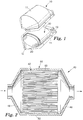
- the catalytic converter 10 generally includes a housing 11 surrounding a catalytic converter element 20.
- the housing 11 has inlet 12 and outlet 13 through which a flow of exhaust gases flows into and out of catalytic converter 10, respectively.
- the housing 11, which is also referred to as a can or a casing, can be made from suitable materials known in the art for such use.
- housing 11 includes one or more metals, metal alloys, and/or intermetallic compositions (hereinafter collectively "metals").
- the housing 11 can be stainless steel.
- Suitable catalytic converter elements also referred to as monoliths, are known in the art and include those made of metal, metal oxides, ceramic, or other materials.
- a variety of ceramic catalytic converter elements are commercially available from a variety of sources. For example, a honeycomb ceramic catalytic converter element is marketed under the trade designation "CELCOR” by Corning Inc., and another is marketed under the trade designation "HONEYCERAM” by NGK Insulated Ltd.
- Metal catalytic converter elements are commercially available from Emitec GmbH and Co. of Lohmar, Germany.
- One or more catalyst materials can be coated onto catalytic converter element 20 in accordance with conventional practices.
- the catalysts used in the catalytic converter element 20 are typically one or more metals (e.g., ruthenium, osmium, rhodium, iridium, nickel, palladium, and platinum) and/or metal oxides (e.g., vanadium pentoxide and titanium dioxide). Most commonly, these catalysts function to oxidize or otherwise eliminate exhaust contaminants such as carbon monoxide and hydrocarbons. Such catalysts also can function to help reduce the amount of oxides of nitrogen in engine exhaust.
- metals e.g., ruthenium, osmium, rhodium, iridium, nickel, palladium, and platinum
- metal oxides e.g., vanadium pentoxide and titanium dioxide.
- these catalysts function to oxidize or otherwise eliminate exhaust contaminants such as carbon monoxide and hydrocarbons.
- Such catalysts also can function to help reduce the amount of oxides
- embodiments of catalytic converter element 20 generally have very thin walls.
- the thin walls can cause the catalytic converter element 20 to be fragile and susceptible to breakage.
- the catalytic converter element 20 can have a coefficient of thermal expansion about an order of magnitude less than that of housing 11. This is particularly the case when housing 11 includes a metal (usually stainless steel) and element 20 is a ceramic.
- the difference in thermal properties can subject catalytic converter element 20 to a risk of damage with changes in temperature.
- Mounting mat or sheet material 30, disposed between housing 11 and element 20, helps protect element 20 from damage due to, for example, road shock and vibration and/or the thermal expansion difference.
- Mounting mat or sheet material 30 also helps prevent exhaust gasses from passing between the element 20 and the metal housing 11.
- FIG 2 shows a representative example of a pollution control device in the form of diesel particulate filter 40.
- the diesel particulate filter or trap 40 is a wall flow filter that includes a honeycombed filter element 42 having a monolithic structure with a bundle of tubes or passageways.
- Such diesel particulate filter elements are commercially available from a number of sources including, for example, Coming Inc. of Coming, NY, and NGK Insulator Ltd. of Nagoya, Japan.
- Useful diesel particulate filter elements are discussed in " Cellular Ceramic Diesel Particulate Filter,” Howitt et al., Paper No. 810114, SAE Technical Paper Series, 1981 .
- a catalyst may be coated onto the filter structure 42 mounted in the diesel particulate filter 40.
- the diesel particulate filter 40 includes a housing 44 having inlet 46 and outlet 48. Housing 44 surrounds particulate filter element 42 (also referred to as a monolith or monolithic structure).
- Mounting mat or sheet material 50 is disposed between the filter element 42 and the metal housing 44 and provides the same benefits as mounting sheet 30 of Figure 1 .
- Relatively small refractory ceramic fibers i.e., those having an average diameter of less than about 5 to 6 micrometers and length greater than about 5 micrometers, have been an important component of known mounting mat compositions for pollution control devices.
- fibers in this size range can be respirable and are often durable in physiological fluids, in particular, lung fluids.
- mounting material compositions lacking durable, respirable, refractory ceramic fibers can be desired. It has been a significant engineering challenge, however, to make acceptable sheet materials, such as mounting mats for pollution control devices, without the durable, respirable, refractory ceramic fibers.
- ceramic fiber compositions alone, while having good temperature resistance can have unsuitable resiliency and can have difficulty in providing acceptable durability at temperatures below which a sufficient holding force is generated by an intumescent component.
- the term "fiber” refers to materials having a length that is greater than its width or diameter. In some embodiments, the length is at least 10 times, at least 100 times, or at least 1000 times the width or diameter.
- respirable refers to fibers that can be inhaled by an animal into the lungs of the animal. Typically, respirable fibers have an average diameter less than about 5 micrometers. In some embodiments, respirable fibers have an average diameter less than about 3 micrometers. Conversely, as used herein, the term “non-respirable” refers to fibers that cannot be inhaled by an animal into the lungs of the animal. Typically, non-respirable fibers have an average diameter of at least about 3 micrometers. In some embodiments, non-respirable fibers have an average diameter of at least about 5 micrometers.
- compositions of the present invention comprise a number of components, which provide desired characteristics to the resulting product. Further, the compositions of the present invention have a structural configuration, which further provide desired characteristics to the resulting product. A description of composition components and structural configuration is given below.
- composition Components A. Composition Components
- compositions of the present invention include an intumescent material, biosoluble fibers, heat treated silica fibers and may also include one or more optional fibers, binders and other additives.
- intumescent material biosoluble fibers
- heat treated silica fibers may also include one or more optional fibers, binders and other additives.
- compositions of the present invention comprise one or more intumescent materials.
- a composition containing one or more intumescent materials can expand when heated and can typically exert sufficient pressure between a pollution control element and the housing of the pollution control device to form a supportive, protective seal when used as a mounting material.
- such a composition can remain resiliently compressible such that the pollution control element is cushioned against physical shocks.
- suitable intumescent materials can include unexpanded vermiculite, vermiculite ore, hydrobiotite, water-swellable synthetic tetrasilicic fluorine type mica described in U.S. Patent No. 3,001,571 (Hatch ), alkali metal silicate granules as described in U.S. Patent No. 4,521,333 (Graham et al. ), expandable graphite, combinations of these, and the like.
- suitable intumescent materials include, for example, granules sold by 3M (St. Paul, MN) under the trade designation "EXPANTROL 4BW". Some of these intumescent materials can exhibit more than 10 percent free expansion in thickness when heated to temperatures above about 200°C or about 300°C. Additionally, some of these intumescent materials can exhibit more than about 50 percent free expansion when heated.
- the intumescent materials used in the present invention desirably have an average particle size greater than about 300 micrometers ( ⁇ m). In some embodiments, a portion of the intumescent material may have a particle size less than 300 ⁇ m, but greater than 150 ⁇ m (i.e., the particles do not pass through a 100 mesh screen). Typically, the intumescent materials have an average particle size ranging from greater than about 300 ⁇ m to about 2000 ⁇ m. In one desired embodiment, the intumescent materials used in the present invention have an average particle size ranging from greater than about 300 ⁇ m to about 800 ⁇ m.
- intumescent material included in the compositions can vary over a wide range. Typically, intumescent material is present in the composition in an amount of up to about 80 percent by weight (pbw) (or up to about 70, 60, 50, 40, 30, 20, or 10 pbw), based on a total dry weight of the composition. In one exemplary embodiment, the composition includes from greater than 0 to about 80 pbw, about 10 to about 70 pbw, about 25 to about 60 pbw, or about 35 to about 50 pbw of one or more intumescent materials based on the total dry weight of the composition.
- compositions of the present invention comprise one or more types of fibers as described below.
- compositions of the present invention comprise biosoluble fibers.
- biosoluble fibers refers to fibers that are decomposable in a physiological medium or a simulated physiological medium.
- Physiological medium includes, but is not limited to, those bodily fluids typically found in the respiratory tract such as, for example, the lungs of animals or humans.
- durable refers to fibers that are not biosoluble.
- Biosolubility can be estimated by observing the effects of direct implantation of the fibers in test animals or by examination of animals or humans that have been exposed to fibers. Biosolubility can also be estimated by measuring the solubility of the fibers as a function of time in simulated physiological medium such as saline solutions, buffered saline solutions, or the like. One such method of determining solubility is described in U. S. Patent No. 5,874, 375 (Zoitas et al. ).
- biosoluble fibers are soluble or substantially soluble in a physiological medium within about 1 year.
- substantially soluble refers to fibers that are at least about 75 weight percent dissolved.
- at least about 50 percent of the fibers are soluble in a physiological medium within about six months.
- at least about 50 percent of the fibers are soluble in a physiological fluid within about three months.
- at least about 50 percent of the biosoluble fibers are soluble in a physiological fluid within at least about 40 days.
- the fibers can be certified by the Fraunhofer Institut as passing the tests for the biopersistence of high temperature insulation fibers in rats after intratracheal instillation (i.e., the fibers have a halftime less than 40 days).
- KI value is calculated by a summation of the weight percentages of alkaline and alkaline-earth oxides and subtraction of two times the weight percent of aluminum oxide in inorganic oxide fibers.
- Inorganic fibers that are biosoluble typically have a KI value of about 40 or greater.
- the biosoluble fibers comprise biosoluble inorganic fibers.
- Biosoluble inorganic fibers suitable for use in the present invention typically include, but are not limited to, inorganic oxides such as, for example, Na 2 O, K 2 O, CaO, MgO, P 2 O 5 , Li 2 O, BaO, or combinations thereof with silica.
- Other metal oxides or other ceramic constituents can be included in the biosoluble inorganic fibers even though these constituents, by themselves, lack the desired solubility but are present in low enough quantities such that the fibers, as a whole, are still decomposable in a physiological medium.
- Such metal oxides include, for example, Al 2 O 3 , TiO 2 , ZrO 2 , B 2 O 3 , and iron oxides.
- the biosoluble inorganic fibers can also include metallic components in amounts such that the fibers are decomposable in a physiological medium or simulated physiological medium.
- the biosoluble inorganic fibers include oxides of silica, magnesium, and calcium. These types of fibers are typically referred to as calcium magnesium silicate fibers.
- the calcium magnesium silicate fibers usually contain less than about 10 weight percent aluminum oxide.
- the fibers include from about 45 to about 90 weight percent SiO 2 , up to about 45 weight percent CaO, up to about 35 weight percent MgO, and less than about 10 weight percent Al 2 O 3 .
- the fibers can contain about 55 to about 75 weight percent SiO 2 , about 25 to about 45 weight percent CaO, about 1 to about 10 weight percent MgO, and less than about 5 weight percent Al 2 O 3 .
- the biosoluble inorganic fibers include oxides of silica and magnesia. These types of fibers are typically referred to as magnesium silicate fibers.
- the magnesium silicate fibers usually contain from about 60 to about 90 weight percent SiO 2 , up to about 35 weight percent MgO (typically, from about 15 to about 30 weight percent MgO), and less than about 5 weight percent Al 2 O 3 .
- the fibers can contain about 70 to about 80 weight percent SiO 2 , about 18 to about 27 weight percent MgO, and less than about 4 weight percent of other trace elements.
- biosoluble inorganic oxides fibers are described in U.S. Patent Nos. 5,332,699 (Olds et al. ); 5,585,312 (Ten Eyck et al. ); 5,714,421 (Olds et al. ); 5,874,375 (Zoitas et al. ); and European Patent Application 02078103.5 filed on July 31, 2002 .
- Various methods can be used to form biosoluble inorganic fibers including, but not limited to, sol gel formation, crystal growing processes, and melt forming techniques such as spinning or blowing.
- Biosoluble fibers are commercially available from Unifrax Corporation (Niagara Falls, NY) under the trade designations "ISOFRAX” and “INSULFRAX.” Other biosoluble fibers are sold by Thermal Ceramics (located in Augusta, GA) under the trade designation "SUPERWOOL.”
- SUPERWOOL 607 contains 60 to 70 weight percent SiO 2 , 25 to 35 weight percent CaO, 4 to 7 weight percent MgO, and a trace amount of Al 2 O 3 .
- SUPERWOOL 607 MAX can be used at a slightly higher temperature and contains 60 to 70 weight percent SiO 2 , 16 to 22 weight percent CaO, 12 to 19 weight percent MgO, and a trace amount of Al 2 O 3 .
- Biosoluble inorganic fibers for use in the present invention can have a wide range of average diameters and average lengths.
- Biosoluble inorganic fibers are commercially available that have an average fiber diameter in the range of about 0.05 micrometers to about 15 micrometers.
- the biosoluble inorganic fibers have average fiber diameters in the range of about 0.1 micrometers to about 5 micrometers (i.e., the fibers are respirable fibers).
- the average diameter of the biosoluble inorganic fibers decreases, an increased amount of the fiber can be incorporated into a given volume of the sheet material. Sheet materials prepared having a higher density of fibers tend to have better resiliency and flexibility.
- the biosoluble inorganic fibers have average fiber diameters greater than about 3.0 micrometers, or greater than about 5 micrometers (i.e., the fibers are non-respirable fibers).
- the biosoluble inorganic fibers used to form a given composition comprise a mixture of non-respirable and respirable fibers.
- the biosoluble inorganic fibers typically have an average fiber length in the range of about 0.1 centimeters to about 3 centimeters. Generally, the length of the biosoluble inorganic fibers is not critical as any selected fiber(s) can be broken down into smaller lengths during the manufacturing process, if desired.
- compositions of the present invention desirably comprise at least about 10 wt% and as much as 90 wt% biosoluble fibers based on a total dry weight of the composition.
- the compositions of the present invention comprise from about 16 to about 80 wt% (or from about 20 to about 80 wt%, from about 30 to about 60 wt%, from about 40 to about 50 wt%) of biosoluble fibers based on a total dry weight of the composition.
- the compositions of the present invention comprise from about 20 to about 60 wt% of biosoluble fibers based on a total dry weight of the composition.
- compositions of the present invention also comprise heat treated silica fibers.
- heat treated silica fibers refers to silica fibers (i) having a silica content of greater than about 67 percent by weight (pbw) based on a total weight of the fibers, and (ii) having been exposed to a heat treatment comprising exposing the fibers to a heat treatment temperature of at least about 400°C for a heat treatment period of at least about 5 minutes.
- Heat treated silica fibers used in the present invention may comprise greater than about 67 pbw up to as much as 99.9 pbw silica based on a total weight of the fibers.
- the heat treated silica fibers comprise greater than about 67 pbw up to as much as 95.0 pbw silica based on a total weight of the fibers.
- heat treated silica fibers of the present invention comprise from about 92.0 pbw to about 95.0 pbw silica, and from about 8.0 pbw to about 5.0 pbw alumina based on a total weight of the fibers.
- the heat treated silica fibers used in the present invention may be heat treated by exposing the fibers to a heat treatment temperature of at least about 400°C or 500°C (or 600°C, 700°C, 800°C, 900°C or 1000°C, or even higher) for a heat treatment period of at least about 5 minutes (10 minutes, 15 minutes, 20 minutes, 25 minutes, 30 minutes, or any 5 minute increment up to about 60 minutes, or longer).
- a heat treatment temperature of at least about 400°C or 500°C (or 600°C, 700°C, 800°C, 900°C or 1000°C, or even higher) for a heat treatment period of at least about 5 minutes (10 minutes, 15 minutes, 20 minutes, 25 minutes, 30 minutes, or any 5 minute increment up to about 60 minutes, or longer).
- heat treated silica fibers used in the present invention are heat treated by (i) heating the fibers from room temperature to a maximum heat treatment temperature ranging from about 600°C to about 1100°C, (ii) maintaining the maximum heat treatment temperature for a heat treatment period of about 5 to about 60 minutes (more typically about 60 minutes), and (iii) allowing the fibers to cool to room temperature.
- heat treated silica fibers used in the present invention are heat treated by (i) heating the fibers from room temperature to a maximum heat treatment temperature of at least about 850°C (desirably from about 850°C to about 1050°C), (ii) maintaining the maximum heat treatment temperature for a heat treatment period of at least about 60 minutes (typically about 60 minutes), and (iii) allowing the fibers to cool to room temperature.
- compositions containing an intumescent material and the above-described biosoluble fibers alone when used as mounting materials, can exhibit desirable mounting properties at high temperatures (i.e., from about 600°C to about 950°C); however, the compositions do not perform as well at intermediate temperatures (i.e., from about 400°C to about 600°C) and at low temperatures (i.e., less than about 400°C).
- intermediate temperatures i.e., from about 400°C to about 600°C
- low temperatures i.e., less than about 400°C.
- the addition of heat treated silica fibers has been discovered to improve the ability of the compositions to hold the pollution control element in position within the pollution control device at intermediate and low temperatures as shown in the Examples below.
- heat treated silica fibers including, but not limited to, leaching processes disclosed in U.S. Patent No. 2,624,658 , U.S. Patent No. 2,718,461 , and U.S. Patent No. 6,468,932 ; and heat treating processes disclosed in U.S. Patent No. 3,498,774 , and U.S. Patent No 4,038,214 .
- Exemplary heat treated high silica content fibers are commercially available from Hitco Carbon Composites, Inc. (Gardena, CA) under the trade designation REFRASIL®, and belChem Fiber Materials GmbH (Freiberg, GERMANY) under the trade designation BELCOTEX®.
- REFRASIL® F100 fiber contains about 96 to 99 wt% SiO 2
- BELCOTEX® fiber contains about 94.5 wt% SiO 2 .
- Suitable heat treated silica fibers for use in the present invention can have a wide range of average diameters and average lengths.
- Heat treated silica fibers are commercially available that have an average fiber diameter in the range of about 0.05 micrometers to about 15 micrometers.
- the heat treated silica fibers have average fiber diameters in the range of about 5.0 micrometers to about 10.0 micrometers (i.e., the fibers are non-respirable fibers).
- the heat treated silica fibers have average fiber diameters in the range of less than about 5.0 micrometers (i.e., the fibers are respirable fibers).
- the heat treated silica fibers used to form a given composition comprise a mixture of non-respirable and respirable fibers.
- the heat treated silica fibers typically have an average fiber length in the range of about 0.1 centimeters to about 3 centimeters. Generally, the length of the heat treated silica fibers is not critical as any selected fiber(s) can be broken down into smaller lengths during the manufacturing process, if desired.
- compositions of the present invention comprise from greater than 0 wt% up to 99 wt% heat treated silica fibers based on a total dry weight of the composition.
- the compositions comprise at least about 4.0 wt% and as much as 90 wt% (or from about 10 to about 90 wt%, from about 20 to about 80 wt%, from about 30 to about 60 wt%, from about 40 to about 50 wt%) of heat treated silica fibers based on a total dry weight of the composition.
- the compositions of the present invention desirably comprise from about 5.0 to about 40 wt%, more desirably from about 8.0 to about 20 wt%, of heat treated silica fibers based on a total dry weight of the composition.
- compositions may optionally include other inorganic fibers in addition to the above-described fibers.
- additional inorganic fibers are desirably non-respirable fibers although additional respirable fibers may also be used.
- Suitable additional fibers include, but are not limited to, fibers formed from ceramic materials such as ceramic oxides, ceramic nitrides, glass materials, or a combination thereof.
- glass refers to an amorphous, inorganic material such as an oxide having a diffuse x-ray diffraction pattern at least substantially without definite lines or other indicia of a crystalline phase.
- compositions of the present invention can include up to about 15 weight percent additional inorganic fibers based on a total dry weight of the composition. In some embodiments, the compositions contain up to about 10 weight percent, up to about 5 weight percent, or up to about 3 weight percent of additional inorganic fibers based on a total dry weight of the composition.
- the additional inorganic fibers may have a fiber length similar to the above-described fiber length of the biosoluble fibers and the heat treated silica fibers. If the additional inorganic fibers are longer than desired when obtained from a desired source, the fibers can be chopped, cut, or otherwise processed to reduce the fiber length to a desired length.
- the additional inorganic fibers typically have an average length in the range of about 0.1 cm to about 1 cm.
- compositions of the present invention may comprise one or more binders.
- Suitable binders include organic binders and may include inorganic binders or a combination thereof.
- the compositions include one or more polymeric or organic binders.
- binders can be used to provide added resiliency and flexibility during formation and during handling of the compositions.
- the composition when the composition is in the form of sheet material, such as a mounting mat for a pollution control device, the mounting mat can be wrapped more easily around the pollution control element.
- the operating temperatures encountered in such a device typically decompose, burn-off or otherwise eliminate the organic constituents.
- the organic constituents are typically transient rather than permanent components of the compositions.
- Polymeric and other organic binders are particularly useful when a mounting mat is made using a wet-laid or modified papermaking process; however, a mat made using a dry-laid process may also benefit from the incorporation of such binders.
- One or more organic binders may be incorporated into the body of the mat and/or used as a coating for the mat.
- the mat may contain very small amounts of organic binder (below 1 wt%) or contain no organic binder.
- Suitable polymeric binders can be thermoplastic or thermoset and can be provided as a solid in various forms or as a liquid comprising a 100 percent solids composition, a solution, dispersion, a latex, an emulsion, combinations of these, and the like.
- the polymeric binder is an elastomer.
- Suitable polymers include, but are not limited to, natural rubber, copolymers of two or more copolymerizable species including styrene and butadiene, copolymers of two or more copolymerizable species including butadiene and acrylonitrile, (meth)acrylate polymers and copolymers, polyurethanes, silicones, polyesters, polyamides, cellulosic polymers, other elastomer polymers, or combinations of these.
- compositions can include about 0.1 to about 15 weight percent, about 0.5 to about 12 weight percent, or about 1 to about 10 weight percent of the organic binder on a dry weight basis.
- the polymer binders are acrylic- and/or methacrylate-containing latex compositions.
- Such latex compositions tend to burn cleanly without producing undesirable amounts of toxic or corrosive by-products.
- suitable acrylic emulsions include, but are not limited to, those commercially available under the trade designations "RHOPLEX HA-8" (a 44.5% by weight solids aqueous emulsion of acrylic copolymers) from Rohm and Haas (Philadelphia, PA) and under the trade designation "AIRFLEX 600BP" (a 55% solids ethylene vinyl acetate copolymer) from Air Products (Allentown, PA).
- the amount of force necessary to move a mounted pollution control element is directly related to the holding force exerted by the mounting mat on the pollution control element.
- a mounted pollution control element e.g., a monolithic catalytic element or carrier
- the longitudinal axis of the pollution control device e.g., a catalytic converter
- the present mounting mat formulation it has been found that by using a binder (e.g., a silicone latex binder) that does not easily burn at the elevated operating temperatures of the pollution control device, instead of a binder (e.g., acrylic latex binders) that does, the holding force exerted by the mounting mat can be significantly increased. In this way, the amount of force needed to axially move the element can be significantly increased.
- silicone binders While not intending to necessarily be bound by any theory, it is believed that this difference in behavior is at least partially the result of there being a lower weight loss when using silicone binders, because the silicone can form solid SiO 2 when exposed to elevated temperatures, rather than being mostly burned off like with the latex binders. It also typically takes higher temperatures to burn the silicone binders.
- silicone latex binders are generally stable up to about 200 °C and acrylic latex binders are generally stable up to about 150 °C. With less mounting material loss, there is typically less of a drop in the pressure exerted by the mounting material, after the pollution control device has been operated.
- a Dow Corning DC85 silicone binder burns out much later than an Airflex 600BP acrylic latex binder, whether exposed to elevated temperatures in an air or N 2 gas environment.
- the mounting mat binder is typically exposed to operating temperatures in the range of from about 200°C to about 300°C. At such relatively low temperatures, the burning/degradation of the organic binder, especially silicone binders, is rather slow. It has been found that up to at least about 30% of the silicone binder remains in the mounting material (i.e., does not burn out), thus reducing the volume loss due to lost binder.
- Polymeric fibers may also be used as a binder component in the compositions to improve the handling, flexibility, the resiliency, or a combination thereof.
- polymeric fibers tend to enhance processing and improve the wet strength of the sheet material.
- polymeric fibers tend to burn out (i.e., to decompose or be eliminated) after one or more heating cycles if the compositions are used in a pollution control device.
- the polymer fibers can be formed from any of the above-mentioned polymers with respect to the polymeric binder.
- the compositions can include up to about 5 weight percent polymeric fibers on a dry weight basis. In some embodiments, the compositions includes up to about 2 or up to about 1 weight percent polymeric fiber. For example, the compositions can include about 0.1 to about 2 weight percent or about 0.2 to about 1.0 weight percent of polymeric fibers on a dry weight basis.
- the polymeric fibers may be staple fibers or fibrillated fibers. In one embodiment, the polymeric fibers are staple fibers in the range of about 0.5 to about 5 denier.
- Suitable polymeric binders may be used alone or may be combined with additional components. Additional components may include, but are not limited to, monomers, plasticizers, fillers, tackifiers, surfactants or other modifiers.
- Suitable inorganic binder materials may include, but are not limited to, colloidal particles; inorganic micaceous binders as disclosed in WO03/031368 , assigned to 3M Innovative Properties Company (St. Paul, MN); and DIXIE CLAY® products commercially available from R.T. Vanderbilt Company, Inc. (Norwalk, CT).
- the micaceous binder as described in WO03/031368 is present in an amount of less than about 5.0 wt% based on a total dry weight of the mat.
- the micaceous binder is present in an amount of less than about 2.0 wt% or 1.0 wt% based on a total dry weight of the mat.
- the composition does not contain any micaceous binder material.
- the mats of the present invention may contain one or more additives to provide a desired characteristic to the resulting product.
- Suitable additives include, but are not limited to, plasticizers, wetting agents, defoaming agents, latex coagulants, clays, lightweight fillers, refractory fillers, metallic fibers, or combinations of these.
- the compositions are in the form of sheet materials, and the sheet materials include an edge protector to minimize erosion to the edges of the sheet material.
- Such erosion can be caused, for example, by the exhaust gas when the sheet material is used in a pollution control device.
- Suitable edge protectors can include, for example, a metal mesh placed on the edges of the sheet or a mixture of a binder and glass as disclosed in U.S. Patent No. 6,245,301 (Stroom et al. ). Other edge protectors know in the art can be used.
- composition components used in the present invention may be configured into a single sheet or may form one or more layers of a multi-layered article.
- the composition is in the form of a single sheet material containing one or more of the above-described composition components.
- the composition typically has an average sheet thickness of up to about 10 cm (4 in), more typically, up to about 4 cm (1.57 in).
- the composition can be in the form of a multilayered construction comprising two or more distinct layers. Each layer may be independently in the form of a sheet material having a similar or different sheet composition than other layers, a coating, a film, or any other layer.
- the multi-layered article comprises a first sheet material containing one or more or all of the above-described composition components, and a second sheet material attached to the first sheet material, wherein the second sheet material comprises a nonwoven mat or layer of ceramic fibers (e.g., polycrystalline ceramic fibers, etc.) or glass fibers (e.g., S2 glass fibers, R glass fibers, E glass fibers, etc.).
- a layer of ceramic fibers can be positioned between the pollution control element (e.g., catalytic element) and the first sheet material, especially when the first sheet material is exposed to hot temperatures (e.g., when the temperature of the gas going into the pollution control device is above about 900 °C).
- the layer of ceramic fibers can insulate and protect the first sheet material from exposure to detrimentally high temperatures (e.g., temperatures that destroy the ability of the intumescent material to expand repeatedly).
- a layer of the glass and/or ceramic fibers can be positioned between the first sheet material and the housing of the pollution control device, especially when the first sheet material is exposed to relatively cold temperatures (e.g., when the temperature of the gas going into the pollution control device is less than about 600 °C).
- the layer of glass and/or ceramic fibers can function to keep the temperature of the first sheet material hot enough so that the intumescent material in the first sheet material is at least partially activated (i.e., expanded).
- a ceramic fiber layer can be positioned between the pollution control element (e.g., catalytic element) and the first sheet material and a layer of glass and/or ceramic fibers can be positioned between the first sheet material and the housing of the pollution control device.
- a sandwiched construction could be desirable when the first sheet material is exposed to relatively intermediate temperatures (e.g., when the temperature of the gas going into the pollution control device is in the range of from about 600 °C to about 900 °C).
- the composition may be formed into objects having a three dimensional shape.
- Suitable objects having a three dimensional shape include, but are not limited to, extruded articles, die casted articles and molded articles.
- compositions can be formed using any of a variety of conventional fabrication techniques.
- One representative fabrication approach involves forming individual sheets of the above-described compositions. Multiple layers of sheet material may be laminated to one another if desired using an adhesive material (or the polymeric binder material when present). Multilayer sheet materials can also be formed as described in U.S. Patent No. 5,853,675 (Howorth ). Alternatively, the layers can be formed one on top of the other as described in U.S. Patent No. 6,051,193 (Langer et al. ).
- the sheet materials prepared from the compositions of the present invention can be formed using any of a variety of suitable techniques such as, for example, a papermaking process.
- an inorganic or polymeric binder is prepared by adding the binder material to water.
- the concentration and temperature can both vary over a wide range.
- warm water such as water at a temperature of about 30°C to about 75°C, can be used to prepare the slurry.
- the water can be at a temperature of about 35°C to about 45°C.
- a dilute slurry can be prepared by adding water to the binder material.
- Biosoluble fibers and heat treated silica fibers can be added to the slurry. Any amount of shear that disperses the binder material and fibers can be used. In some embodiments, low to moderate shear for a relatively brief time, e.g., 1 second to 10 minutes or about 3 to 80 seconds, can be used to disperse the fibers.
- the slurry can be mixed at moderate speed to keep the solid ingredients suspended. Other ingredients such as a defoaming agent and polymeric binders can be added.
- a suitable coagulating agent such as an acidifying agent can also be added.
- Other coagulating agents such as one that can cause coagulation via basic means, can also be used in accordance with conventional practices.
- larger particles of the polymeric binder when present, typically form. Any particulate matter present in the composition tends to bind to the binder and become trapped in the fiber matrix. That is, the particulate matter does not cause clogging of screens used for filtering. Binding the particulate matter to the fiber matrix facilities draining the water from the slurry and can decrease the processing time needed to prepare sheet material.
- the intumescent material desirably having an average particle size greater than about 300 micrometers, is typically added after coagulation. This particular order of addition can also facilitate dispersing the solids in the slurry and removing the water from the slurry. However, the order of addition is not critical and other orders of addition are acceptable.
- the resultant slurry composition can be cast onto a suitable screen, drained, and pressed.
- the plies can be formed by vacuum casting the slurry onto a wire mesh or screen.
- the resultant pressed sheet material can be dried in any suitable manner, e.g., air dried or oven dried.
- the sheet material can be cut into a desired shape such as a shape suitable for use as a mounting mat or for use as a heat barrier (i.e., insulating material) in the end-cone region of a pollution control device. Cutting can be accomplished, for example, by using a die stamping process.
- the sheet materials prepared from the compositions of the invention can be reproducibly cut to satisfy stringent size tolerances.
- the sheet materials can exhibit suitable handling properties and are not so brittle as to crumble in one's hand.
- the sheet materials can be easily and flexibly fitted around a pollution control element without breaking apart to form a resilient, protective, supportive seal in a pollution control device.
- compositions of the present invention can also be prepared in the form of a paste.
- the total solids are typically higher than about 30 percent. In some embodiments, the solids are about 30 to about 60 percent.
- the paste typically has a consistency and viscosity that can be injected, for example, into the gap between a pollution control element and the housing of a pollution control device.
- U.S. Patent No. 5,736,109 (Howorth ) describes a suitable process for making a paste.
- a paste can also be formed by initially forming a slurry and then removing some of the water to increase the percent solids.
- the paste can be used to form a sheet material or a three-dimensional object. To form a sheet material or a three-dimensional object, the composition can be cast in a three-dimensional die, molded, or extruded through a die.
- compositions are dry-laid along with the above-mentioned intumescent materials.
- One or more single layers of composition in the form of a sheet material may be combined with other identical, similar or different layers to form multi-layered articles using known techniques. For example, additional layers may be coated onto an outer surface of the sheet material. Further, as described above, multiple layers of sheet material or other layers may be laminated to one another using an optional adhesive. Other mechanical methods of combining multiple layers of material to form multi-layered articles include, but are not limited to, needlepunching, stitching, etc.
- the durability and performance of a mounting mat in a pollution control device such as, for example, a catalytic converter assembly, under simulated operating conditions, can be measured, for example, according to the test described in the SAE Paper 2004-01-0146 titled “Catalytic Converter Hot Vibration Test Methods at 3M Company", Nathan Brunner .
- a mounting mat is wrapped around a cylindrical cordierite monolith having an approximate diameter of 4.7 inches (about 119.4 mm), a length of about 3 inches (about 76.2 mm), and a weight of about 260 grams.
- the wrapped monolith is canned in a catalytic converter housing to the mount density specified in the examples, and is subjected to hot vibration testing with a gas inlet temperature of 500°C.
- the converter assembly is thermally conditioned for 5 cycles of heating for 2 hours with hot inlet gas and cooling for 1 hour.
- the test begins with a 4-hour cycle of 3 hours of heating, using hot inlet gas at a temperature of 500°C while vibrating at 2.7 grms -12 dB (decibels). The cycle ends with cooling for 1 hour, which cools the assembly to about ambient temperature.
- the second 4-hour cycle starts at -9 dB, the third starts at -6 dB, etc. until 0 dB is reached. If the assembly is still intact, the test continues with 4-hour cycles at 0 dB until failure or until a designated time is reached, typically 72 hours or 96 hours.
- Chopped silica fibers (7 micron diameter, 6 mm length BELCOTEX® fiber, available from belChem fiber materials Gmbh, Freiburg, Germany) were heat treated by placing the fibers in a furnace at ambient temperature. The furnace was turned on with the controller set at 950°C. When the temperature in the furnace reached 950°C, the fibers were allowed to soak for 1 hour, and then the furnace was turned off. When the furnace cooled to ambient temperature, the fibers were removed for making into sheets.
- a mat was prepared having a dry composition of 27 wt% heat treated silica fiber described above, 27 wt% biosoluble fiber (SUPERWOOL 607 available from Thermal Ceramic, Augusta, GA), 8 wt% vinyl acetate latex solids (AIRFLEX 600BP vinyl acetate latex having a solids of about 55% available from Air Products Polymers L.P., Allentown, PA) and 38 wt% unexpanded vermiculite.
- SUPERWOOL 607 available from Thermal Ceramic, Augusta, GA
- 8 wt% vinyl acetate latex solids having a solids of about 55% available from Air Products Polymers L.P., Allentown, PA
- 38 wt% unexpanded vermiculite 38 wt% unexpanded vermiculite.
- a slurry was prepared by adding 3000 ml of tap water heated to 40°C to a blender, adding the heat treated silica fibers, and mixing for 10 seconds. The biosoluble fibers were added and mixed on low speed for 5 seconds. The slurry was transferred to large mixing container; fibers from the blender were rinsed using 1000 ml of 40°C tap water and added to the slurry in the container. The slurry was mixed with a propeller blade mixer at medium speed while adding three drops of defoamer (FOAMASTER 111 defoamer) and the vinyl acetate latex. When dispersed, 11.4 grams of a 50 wt% Alum solution (General Chemicals) was added and mixed for about 2 minutes.
- the resulting mat was canned to a mount density of 0.76 g/cc and subjected to hot vibration testing as described above. The test reached the 0 dB level, and after 72 hours the test was discontinued. No failure was observed in the mat or the canned assembly.
- Biosoluble fibers (ISOFRAX available from Unifrax) were pulped twice for 60 seconds in water heated to about 40°C at about 1.05 percent solids by weight. The slurry was pumped to a holding tank and diluted to about 0.84 % solids. The diluted slurry was pumped through a cyclone separator to a second holding tank to reduce the shot by about 20%. Silica fibers (BELCOTEX®), heat treated as described above, were pulped for 3 minutes at about 0.37 wt% solids and transferred to the tank with the biosoluble fibers and the slurry was further diluted to about 0.35 wt% by solids.
- Silica fibers BELCOTEX®
- the diluted slurry was heated to 40°C, and latex (AIRFLEX 600 BP) and sodium aluminate (1.18% of the weight of the fibers) were added while mixing to keep the slurry in suspension. After about 3 minutes, a 50 wt% alum solution in water (0.18 wt% alum based on the total slurry weight) was added to precipitate the latex and fibers. The slurry was then continuously pumped into a tank and mixed with unexpanded vermiculite that was metered into the slurry. The resulting slurry was pumped through a manifold onto a mesh belt. A vacuum was used to dewater the slurry and form a mat having about 30-40 wt% water.
- the mat was pressed with a roller and passed through a series of rotating steam heated cans to dry and form a mat having a dry composition of 31.1 wt% biosoluble fiber, 20.7 wt% heat treated silica fiber, 8.2 wt% latex solids, and 40 wt% unexpanded vermiculite.
- the mat was canned to a mount density of about 0.70 g/cc and subjected to hot vibration testing as described above with an inlet gas temperature of 500°C. The test reached the 0 dB level, and after 96 hours (24 full cycles) the test was discontinued. No failure in the mat or the canned assembly was observed.
- a mat was prepared according to Example 2 except as noted.
- the biosoluble fibers (ISOFRAX) were pulped at 1.68 wt% solids. After the first dilution with water for shot removal, the slurry was about 1.05 wt% solids.
- the heat-treated silica fiber was pulped at 0.32 wt% solids, and the final slurry contained about 0.629 wt% solids.
- Sodium aluminate was added at a level of 1.15 wt% of the total dry fiber weight.
- the resulting mat had a dry composition of 39.6 wt% biosoluble fibers, 9.9 wt% heat-treated silica fibers, 10.3 wt% latex solids, and 40.2 wt% unexpanded vermiculite.
- the mat was canned at a mount density of 0.70 g/cc and subjected to hot vibration testing using a hot gas inlet temperature of 500°C. The test reached the 0 dB level, and the test was discontinued after 96 hours. No failure was observed in the mat or canned assembly.
- a mat was prepared according to Example 3 except as noted.
- BELCOTEX® high silica content fibers were heat treated @ 900°C.
- the resulting mounting mat had a dry composition of about 10.2 % by weight (wt.) of BELCOTEX® high silica content fibers, about 40.8 % by wt. of ISOFRAX 1260 biosoluble fibers, about 40 % by wt. of unexpanded vermiculite from Cometals, located at One Penn Plaza, New York, NY, and about 9 % by wt. of AIRFLEX 600BP acrylic latex binder.
- An alternative mounting mat material can also be constructed as described in, and using the same components, in the above Example 4, with the exception that the acrylic latex binder is replaced with the same amount of DOW CORNING DC85 silicone binder.
- the organic binder used in the present inventive mounting material may comprise, consist of, or consist essentially of, for example, an acrylic latex binder, a silicone binder or a combination of both.
- the dry weight composition of the present inventive mounting material may be varied as much as the following: (a) in the range of from about 2% to about 80% by wt. of heat treated high silica content fiber, (b) at least some up to about 75% by wt. of biosoluble ceramic fiber, (c) in the range of from about 10% to about 75% by wt. of intumescent material (e.g., unexpanded vermiculite), and (d) in the range of from about 1% to about 15% by wt. of organic binder.
- the total fiber content i.e., the combination of the silica and bio-soluble fiber
- the dry weight composition of desirable mounting materials according to the present invention can vary as follows: (a) in the range of from about 5% to about 50% by wt. of heat treated high silica content fiber, (b) in the range of from about 10% to about 60% by wt. of biosoluble ceramic fiber, (c) in the range of from about 20% to about 70% by wt. of intumescent material (e.g., unexpanded vermiculite), and (d) in the range of from about 2% to about 12% by wt. of organic binder.
- the total fiber content i.e., the combination of the silica and bio-soluble fiber
- the total fiber content i.e., the combination of the silica and bio-soluble fiber
- the preferred dry weight composition of the present inventive mounting material can vary as follows: (a) in the range of from about 5% to about 25% by wt. of heat treated high silica content fiber, (b) in the range of from about 20% to about 50% by wt. of biosoluble ceramic fiber, (c) in the range of from about 25% to about 60% by wt. of intumescent material (e.g., unexpanded vermiculite), and (d) in the range of from about 4% to about 11% by wt. of organic binder.
- the total fiber content i.e., the combination of the silica and bio-soluble fiber
- compositions of the present invention may also be useful as heat barriers (i.e., insulating materials), fire barriers or stops, or a combination thereof.
- heat barriers i.e., insulating materials
- fire barriers or stops or a combination thereof.
- it may be useful to wrap or otherwise place the present compositions around pipes, heating devices, or structural elements such as building supports.
- the compositions of the present invention may also be useful around the monolithic structure of a fuel cell.
Description
- The present invention relates to materials suitable for use in pollution control devices, in particular, to mats for mounting a pollution control element in a pollution control device and, more particularly, pollution control devices containing such materials.
- Pollution control devices are used on motor vehicles to reduce atmospheric pollution. Such pollution control devices include one or more pollution control elements mounted within a housing. Two types of devices are currently in widespread use: catalytic converters and diesel particulate filters or traps. Catalytic converters contain one or more catalysts, which are coated onto a substrate typically in the form of a monolithic structure. The monolithic structures are typically ceramic, although metal monoliths have been used. The catalyst(s) oxidize carbon monoxide and hydrocarbons, reduce the oxides of nitrogen in exhaust gases, or a combination thereof. Diesel particulate filters or traps typically include a wall flow filter element in the form of a honeycombed monolithic structure made from porous crystalline ceramic materials. In the current state-of-the-art construction of these pollution control devices, the monolithic structure of each type is enclosed within a housing.
- A typical monolithic pollution control element generally has relatively thin walls to provide a large amount of surface area. Consequently, the structure is relatively fragile and susceptible to breakage. The typical monolithic pollution control element formed from ceramic material tends to have a coefficient of thermal expansion that is an order of magnitude less than the metal (usually stainless steel) housing or can in which it is contained. Protective packing or mounting materials such as intumescent or non-intumescent mats are typically packed between the ceramic monolith and the metal housing to avoid damage to the monolith from, for example, road shock and vibration, to compensate for the thermal expansion difference, and to prevent exhaust gases from passing between the monolith and the metal housing. The process of placing or inserting the mounting material is referred to as "canning" and includes such processes as injecting a paste into a gap between the monolith and the metal housing, or wrapping a sheet material (i.e., mounting mat) around the monolith and inserting the wrapped monolith into the housing.
- Compositions used to form conventional mounting materials have included refractory ceramic fibers that can provide properties such as high temperature durability, good handling, resiliency, flexibility, and strength. Intumescent materials have also been used that volumetrically expand at elevated temperatures. Such expansion can help to hold the monolith in place during use at high temperatures. Materials that have been used for mounting pollution control elements in the housing of a pollution control device are described in, for example, Published German Patent Application No.
DE 19858025 (Asglawo ); andU. S. Patents Nos. 3,916,057 (Hatch et al. );4,305,992 (Langer et al. );4,385,135 (Langer et al. );5,254,410 (Langer et al. ); and5,242,871 (Hashimoto et al. ). - Relatively small refractory ceramic fibers, i.e., those having a diameter of less than about 5 to 6 micrometers, have been an important component of mat compositions. However, small fibers may be troublesome in some instances. Small fibers are deemed to be respirable and are usually durable in physiological fluids, in particular, lung fluids. Thus, there is a desire for mounting mat compositions in which the use of durable, respirable refractory fibers could be avoided. It has been a significant engineering challenge, however, to make an acceptable mounting mat without this component.
- Fibers that are non-durable in physiological fluids have been described in various references including
U.S. Patent No. 5,874,375 and described references therein. When such a fiber is inhaled, it decomposes in body fluids. Unfortunately, soluble inorganic fibers by themselves are not a practical substitute for refractory fibers. This lack of interchangeability can be attributed to faults that burden soluble inorganic fibers. Such fibers tend to exhibit excessive shrinkage when subjected to the temperature extremes encountered in a typical catalytic converter. Mat shrinkage can allow a fragile catalytic converter element to be loosely held inside its housing resulting in potential damage to the monolith and thus the pollution control device. -
US 2004/0234436 A1 discloses a composition comprising a micaceous binder in an amount of about 5 to about 80 weight percent on a dry weight basis and biosoluble inorganic fibers in an amount of about 5 to about 90 weight percent on a dry weight basis. -
DE 198 58 025 A1 discloses a mat for holding a vehicle exhaust gas purification catalyst in a metal housing, which consists of a composite of comminuted silica filaments, binder and embedded particles of material (partly graphite) undergoing temperature-dependent expansion, the silica filaments being thermally pretreated so that they have no temperature-dependent shrinkage at the operating temperature of the mat. - There is a continuing need for improvements to such mounting mat compositions. The present invention provides such improved compositions.
- It has been found that some known mounting materials only exhibit desirable mounting properties at relatively high operating temperatures (i.e., from about 700°C to about 950°C). These same mounting materials exhibit less than desirable mounting properties at relatively intermediate operating temperatures (i.e., from about 400°C to about 600°C) and/or at relatively low operating temperatures (i.e., less than about 400°C). The present inventors have uncovered a synergistic combination of mounting materials that together can exhibit desirable mounting properties at not only such relatively high operating temperatures, but also at relatively intermediate operating temperatures, and/or relatively low operating temperatures. Thus, the present invention addresses the need for a more universal mounting material. The present invention can also address the need for such a mounting material that avoids the use of respirable, non-decomposable refractory fibers.
- The present invention is defined by independent claim 1, the dependent claims being directed to preferred embodiments.
- The present invention may be more completely understood in consideration of the following detailed description of various embodiments of the invention in connection with the accompanying drawings, in which:
-
Figure 1 is a perspective view of a catalytic converter incorporating an embodiment of the present invention and shown in disassembled relation; and -
Figure 2 is a longitudinal central section through a diesel particulate filter incorporating an embodiment of the present invention. - The present invention is directed to compositions that may be used as mounting materials in pollution control devices. In particular, the compositions include biosoluble fibers, heat treated silica fibers having a silica content of greater than about 67 percent by weight (pbw) based on a total weight of the fibers, and intumescent material, and one or more optional binders. The compositions can be, for example, in the form of a paste but are preferably in the form of a sheet material.
- The mounting material compositions can be used, for example, between the fragile monolith structure of a pollution control element and the housing of a pollution control device. That is, the compositions can be disposed in the gap between the pollution control element and the housing of a pollution control device. The compositions can be, for example, in the form of a paste or a sheet material. In one embodiment, the sheet material is in the form of a mounting mat that is wrapped around at least a portion of the pollution control element. The wrapped pollution control element is placed in the housing of the pollution control device. In another embodiment, the compositions are in the form of a paste. Such a paste may be injected or otherwise inserted into a gap in the pollution control device between at least a portion of the pollution control element and the housing. For example, the paste may be preformed (e.g., molded) into a shape desired for the gap and then inserted into the gap.
- The compositions of the present invention may also be useful in pollution control devices as an insulating material. For example, the compositions may be positioned in the inlet or outlet regions (i.e., the end cone regions) of a pollution control device. For example, the inlet and/or outlet regions may each be defined by an inner end cone housing and an outer end cone housing, with the present composition disposed between the inner and outer end cone housings. The compositions may also be used to insulate the rest of the exhaust system as well as the engine from the temperatures encountered while in use. For example, one or more sections of the exhaust pipe may have a double-walled construction (i.e., an inner and outer wall), with the present composition disposed between the two walls.
- When the composition is in the form of a sheet material, the sheet material can be cut or otherwise shaped to form the desired mounting mat, or insulating component (e.g., end cone), for the pollution control device. Alternatively, the composition may be molded into a desired intermediate or final shape. For example, the present composition may be molded into a flat sheet material having the desired final dimensions and then deformed into the desired final shape. For example, a molded flat mounting mat could be wrapped around the pollution control element before being installed into the pollution control device. In addition, a molded flat end cone insulation sheet could be wrapped around the inner end cone housing and then disposed within the outer end cone housing.
- An illustrative example of a pollution control device in the form of
catalytic converter 10 is shown inFigure 1 . Thecatalytic converter 10 generally includes ahousing 11 surrounding acatalytic converter element 20. Thehousing 11 hasinlet 12 andoutlet 13 through which a flow of exhaust gases flows into and out ofcatalytic converter 10, respectively. Thehousing 11, which is also referred to as a can or a casing, can be made from suitable materials known in the art for such use. Typically,housing 11 includes one or more metals, metal alloys, and/or intermetallic compositions (hereinafter collectively "metals"). For example, thehousing 11 can be stainless steel. - Suitable catalytic converter elements, also referred to as monoliths, are known in the art and include those made of metal, metal oxides, ceramic, or other materials. A variety of ceramic catalytic converter elements are commercially available from a variety of sources. For example, a honeycomb ceramic catalytic converter element is marketed under the trade designation "CELCOR" by Corning Inc., and another is marketed under the trade designation "HONEYCERAM" by NGK Insulated Ltd. Metal catalytic converter elements are commercially available from Emitec GmbH and Co. of Lohmar, Germany.
- One or more catalyst materials can be coated onto
catalytic converter element 20 in accordance with conventional practices. The catalysts used in thecatalytic converter element 20 are typically one or more metals (e.g., ruthenium, osmium, rhodium, iridium, nickel, palladium, and platinum) and/or metal oxides (e.g., vanadium pentoxide and titanium dioxide). Most commonly, these catalysts function to oxidize or otherwise eliminate exhaust contaminants such as carbon monoxide and hydrocarbons. Such catalysts also can function to help reduce the amount of oxides of nitrogen in engine exhaust. - To provide a large amount of surface area, embodiments of
catalytic converter element 20 generally have very thin walls. The thin walls can cause thecatalytic converter element 20 to be fragile and susceptible to breakage. Additionally, in some embodiments, thecatalytic converter element 20 can have a coefficient of thermal expansion about an order of magnitude less than that ofhousing 11. This is particularly the case whenhousing 11 includes a metal (usually stainless steel) andelement 20 is a ceramic. The difference in thermal properties can subjectcatalytic converter element 20 to a risk of damage with changes in temperature. Mounting mat orsheet material 30, disposed betweenhousing 11 andelement 20, helps protectelement 20 from damage due to, for example, road shock and vibration and/or the thermal expansion difference. Mounting mat orsheet material 30 also helps prevent exhaust gasses from passing between theelement 20 and themetal housing 11. -
Figure 2 shows a representative example of a pollution control device in the form ofdiesel particulate filter 40. The diesel particulate filter ortrap 40 is a wall flow filter that includes ahoneycombed filter element 42 having a monolithic structure with a bundle of tubes or passageways. Such diesel particulate filter elements are commercially available from a number of sources including, for example, Coming Inc. of Coming, NY, and NGK Insulator Ltd. of Nagoya, Japan. Useful diesel particulate filter elements are discussed in "Cellular Ceramic Diesel Particulate Filter," Howitt et al., Paper No. 810114, SAE Technical Paper Series, 1981. - A catalyst may be coated onto the
filter structure 42 mounted in thediesel particulate filter 40. Thediesel particulate filter 40 includes ahousing 44 havinginlet 46 andoutlet 48.Housing 44 surrounds particulate filter element 42 (also referred to as a monolith or monolithic structure). Mounting mat orsheet material 50 is disposed between thefilter element 42 and themetal housing 44 and provides the same benefits as mountingsheet 30 ofFigure 1 . - Relatively small refractory ceramic fibers, i.e., those having an average diameter of less than about 5 to 6 micrometers and length greater than about 5 micrometers, have been an important component of known mounting mat compositions for pollution control devices. However, fibers in this size range can be respirable and are often durable in physiological fluids, in particular, lung fluids. Thus, mounting material compositions lacking durable, respirable, refractory ceramic fibers can be desired. It has been a significant engineering challenge, however, to make acceptable sheet materials, such as mounting mats for pollution control devices, without the durable, respirable, refractory ceramic fibers. Additionally, ceramic fiber compositions alone, while having good temperature resistance, can have unsuitable resiliency and can have difficulty in providing acceptable durability at temperatures below which a sufficient holding force is generated by an intumescent component.
- As used herein, the term "fiber" refers to materials having a length that is greater than its width or diameter. In some embodiments, the length is at least 10 times, at least 100 times, or at least 1000 times the width or diameter.
- As used herein, the term "respirable" refers to fibers that can be inhaled by an animal into the lungs of the animal. Typically, respirable fibers have an average diameter less than about 5 micrometers. In some embodiments, respirable fibers have an average diameter less than about 3 micrometers. Conversely, as used herein, the term "non-respirable" refers to fibers that cannot be inhaled by an animal into the lungs of the animal. Typically, non-respirable fibers have an average diameter of at least about 3 micrometers. In some embodiments, non-respirable fibers have an average diameter of at least about 5 micrometers.
- The compositions of the present invention comprise a number of components, which provide desired characteristics to the resulting product. Further, the compositions of the present invention have a structural configuration, which further provide desired characteristics to the resulting product. A description of composition components and structural configuration is given below.
- The compositions of the present invention include an intumescent material, biosoluble fibers, heat treated silica fibers and may also include one or more optional fibers, binders and other additives. A description of each class of components is given below.
- The compositions of the present invention comprise one or more intumescent materials. A composition containing one or more intumescent materials can expand when heated and can typically exert sufficient pressure between a pollution control element and the housing of the pollution control device to form a supportive, protective seal when used as a mounting material. In some embodiments, such a composition can remain resiliently compressible such that the pollution control element is cushioned against physical shocks.
- Examples of suitable intumescent materials can include unexpanded vermiculite, vermiculite ore, hydrobiotite, water-swellable synthetic tetrasilicic fluorine type mica described in
U.S. Patent No. 3,001,571 (Hatch ), alkali metal silicate granules as described inU.S. Patent No. 4,521,333 (Graham et al. ), expandable graphite, combinations of these, and the like. Other suitable intumescent materials include, for example, granules sold by 3M (St. Paul, MN) under the trade designation "EXPANTROL 4BW". Some of these intumescent materials can exhibit more than 10 percent free expansion in thickness when heated to temperatures above about 200°C or about 300°C. Additionally, some of these intumescent materials can exhibit more than about 50 percent free expansion when heated. - The intumescent materials used in the present invention desirably have an average particle size greater than about 300 micrometers (µm). In some embodiments, a portion of the intumescent material may have a particle size less than 300 µm, but greater than 150 µm (i.e., the particles do not pass through a 100 mesh screen). Typically, the intumescent materials have an average particle size ranging from greater than about 300 µm to about 2000 µm. In one desired embodiment, the intumescent materials used in the present invention have an average particle size ranging from greater than about 300 µm to about 800 µm.
- The amount of intumescent material included in the compositions can vary over a wide range. Typically, intumescent material is present in the composition in an amount of up to about 80 percent by weight (pbw) (or up to about 70, 60, 50, 40, 30, 20, or 10 pbw), based on a total dry weight of the composition. In one exemplary embodiment, the composition includes from greater than 0 to about 80 pbw, about 10 to about 70 pbw, about 25 to about 60 pbw, or about 35 to about 50 pbw of one or more intumescent materials based on the total dry weight of the composition.
- The compositions of the present invention comprise one or more types of fibers as described below.
- The compositions of the present invention comprise biosoluble fibers. As used herein, "biosoluble fibers" refers to fibers that are decomposable in a physiological medium or a simulated physiological medium. Physiological medium includes, but is not limited to, those bodily fluids typically found in the respiratory tract such as, for example, the lungs of animals or humans. As used herein, "durable" refers to fibers that are not biosoluble.
- Biosolubility can be estimated by observing the effects of direct implantation of the fibers in test animals or by examination of animals or humans that have been exposed to fibers. Biosolubility can also be estimated by measuring the solubility of the fibers as a function of time in simulated physiological medium such as saline solutions, buffered saline solutions, or the like. One such method of determining solubility is described in U. S. Patent No.
5,874, 375 (Zoitas et al. ). - Typically, biosoluble fibers are soluble or substantially soluble in a physiological medium within about 1 year. As used herein, the term "substantially soluble" refers to fibers that are at least about 75 weight percent dissolved. In some embodiments, at least about 50 percent of the fibers are soluble in a physiological medium within about six months. In other embodiments, at least about 50 percent of the fibers are soluble in a physiological fluid within about three months. In still other embodiments, at least about 50 percent of the biosoluble fibers are soluble in a physiological fluid within at least about 40 days. For example, the fibers can be certified by the Fraunhofer Institut as passing the tests for the biopersistence of high temperature insulation fibers in rats after intratracheal instillation (i.e., the fibers have a halftime less than 40 days).
- Yet another approach to estimating the biosolubility of fibers is based on the composition of the fibers. For example, Germany classifies respirable inorganic oxide fibers based on a carcingenicity index (KI value). The KI value is calculated by a summation of the weight percentages of alkaline and alkaline-earth oxides and subtraction of two times the weight percent of aluminum oxide in inorganic oxide fibers. Inorganic fibers that are biosoluble typically have a KI value of about 40 or greater.
- In one desired embodiment of the present invention, the biosoluble fibers comprise biosoluble inorganic fibers. Biosoluble inorganic fibers suitable for use in the present invention typically include, but are not limited to, inorganic oxides such as, for example, Na2O, K2O, CaO, MgO, P2O5, Li2O, BaO, or combinations thereof with silica. Other metal oxides or other ceramic constituents can be included in the biosoluble inorganic fibers even though these constituents, by themselves, lack the desired solubility but are present in low enough quantities such that the fibers, as a whole, are still decomposable in a physiological medium. Such metal oxides include, for example, Al2O3, TiO2, ZrO2, B2O3, and iron oxides. The biosoluble inorganic fibers can also include metallic components in amounts such that the fibers are decomposable in a physiological medium or simulated physiological medium.
- In one embodiment, the biosoluble inorganic fibers include oxides of silica, magnesium, and calcium. These types of fibers are typically referred to as calcium magnesium silicate fibers. The calcium magnesium silicate fibers usually contain less than about 10 weight percent aluminum oxide. In some embodiments, the fibers include from about 45 to about 90 weight percent SiO2, up to about 45 weight percent CaO, up to about 35 weight percent MgO, and less than about 10 weight percent Al2O3. For example, the fibers can contain about 55 to about 75 weight percent SiO2, about 25 to about 45 weight percent CaO, about 1 to about 10 weight percent MgO, and less than about 5 weight percent Al2O3.
- In a further embodiment, the biosoluble inorganic fibers include oxides of silica and magnesia. These types of fibers are typically referred to as magnesium silicate fibers. The magnesium silicate fibers usually contain from about 60 to about 90 weight percent SiO2, up to about 35 weight percent MgO (typically, from about 15 to about 30 weight percent MgO), and less than about 5 weight percent Al2O3. For example, the fibers can contain about 70 to about 80 weight percent SiO2, about 18 to about 27 weight percent MgO, and less than about 4 weight percent of other trace elements.
- Suitable biosoluble inorganic oxides fibers are described in
U.S. Patent Nos. 5,332,699 (Olds et al. );5,585,312 (Ten Eyck et al. );5,714,421 (Olds et al. );5,874,375 (Zoitas et al. ); and European Patent Application02078103.5 filed on July 31, 2002 - Biosoluble fibers are commercially available from Unifrax Corporation (Niagara Falls, NY) under the trade designations "ISOFRAX" and "INSULFRAX." Other biosoluble fibers are sold by Thermal Ceramics (located in Augusta, GA) under the trade designation "SUPERWOOL." For example, SUPERWOOL 607 contains 60 to 70 weight percent SiO2, 25 to 35 weight percent CaO, 4 to 7 weight percent MgO, and a trace amount of Al2O3. SUPERWOOL 607 MAX can be used at a slightly higher temperature and contains 60 to 70 weight percent SiO2, 16 to 22 weight percent CaO, 12 to 19 weight percent MgO, and a trace amount of Al2O3.
- Suitable biosoluble inorganic fibers for use in the present invention can have a wide range of average diameters and average lengths. Biosoluble inorganic fibers are commercially available that have an average fiber diameter in the range of about 0.05 micrometers to about 15 micrometers. In some embodiments, the biosoluble inorganic fibers have average fiber diameters in the range of about 0.1 micrometers to about 5 micrometers (i.e., the fibers are respirable fibers). As the average diameter of the biosoluble inorganic fibers decreases, an increased amount of the fiber can be incorporated into a given volume of the sheet material. Sheet materials prepared having a higher density of fibers tend to have better resiliency and flexibility. In other embodiments, the biosoluble inorganic fibers have average fiber diameters greater than about 3.0 micrometers, or greater than about 5 micrometers (i.e., the fibers are non-respirable fibers). In still other embodiments, the biosoluble inorganic fibers used to form a given composition comprise a mixture of non-respirable and respirable fibers.
- The biosoluble inorganic fibers typically have an average fiber length in the range of about 0.1 centimeters to about 3 centimeters. Generally, the length of the biosoluble inorganic fibers is not critical as any selected fiber(s) can be broken down into smaller lengths during the manufacturing process, if desired.
- The compositions of the present invention desirably comprise at least about 10 wt% and as much as 90 wt% biosoluble fibers based on a total dry weight of the composition. Typically, the compositions of the present invention comprise from about 16 to about 80 wt% (or from about 20 to about 80 wt%, from about 30 to about 60 wt%, from about 40 to about 50 wt%) of biosoluble fibers based on a total dry weight of the composition. In one desired embodiment, the compositions of the present invention comprise from about 20 to about 60 wt% of biosoluble fibers based on a total dry weight of the composition.
- The compositions of the present invention also comprise heat treated silica fibers. As used herein, the term "heat treated silica fibers" refers to silica fibers (i) having a silica content of greater than about 67 percent by weight (pbw) based on a total weight of the fibers, and (ii) having been exposed to a heat treatment comprising exposing the fibers to a heat treatment temperature of at least about 400°C for a heat treatment period of at least about 5 minutes. Heat treated silica fibers used in the present invention may comprise greater than about 67 pbw up to as much as 99.9 pbw silica based on a total weight of the fibers. Typically, the heat treated silica fibers comprise greater than about 67 pbw up to as much as 95.0 pbw silica based on a total weight of the fibers. In one desired embodiment, heat treated silica fibers of the present invention comprise from about 92.0 pbw to about 95.0 pbw silica, and from about 8.0 pbw to about 5.0 pbw alumina based on a total weight of the fibers.
- Further, the heat treated silica fibers used in the present invention may be heat treated by exposing the fibers to a heat treatment temperature of at least about 400°C or 500°C (or 600°C, 700°C, 800°C, 900°C or 1000°C, or even higher) for a heat treatment period of at least about 5 minutes (10 minutes, 15 minutes, 20 minutes, 25 minutes, 30 minutes, or any 5 minute increment up to about 60 minutes, or longer). In one exemplary embodiment, heat treated silica fibers used in the present invention are heat treated by (i) heating the fibers from room temperature to a maximum heat treatment temperature ranging from about 600°C to about 1100°C, (ii) maintaining the maximum heat treatment temperature for a heat treatment period of about 5 to about 60 minutes (more typically about 60 minutes), and (iii) allowing the fibers to cool to room temperature. In one desired embodiment, heat treated silica fibers used in the present invention are heat treated by (i) heating the fibers from room temperature to a maximum heat treatment temperature of at least about 850°C (desirably from about 850°C to about 1050°C), (ii) maintaining the maximum heat treatment temperature for a heat treatment period of at least about 60 minutes (typically about 60 minutes), and (iii) allowing the fibers to cool to room temperature.
- It has been discovered that compositions containing an intumescent material and the above-described biosoluble fibers alone (i.e., without heat treated silica fibers), when used as mounting materials, can exhibit desirable mounting properties at high temperatures (i.e., from about 600°C to about 950°C); however, the compositions do not perform as well at intermediate temperatures (i.e., from about 400°C to about 600°C) and at low temperatures (i.e., less than about 400°C). The addition of heat treated silica fibers has been discovered to improve the ability of the compositions to hold the pollution control element in position within the pollution control device at intermediate and low temperatures as shown in the Examples below.
- Various methods can be used to form heat treated silica fibers including, but not limited to, leaching processes disclosed in
U.S. Patent No. 2,624,658 ,U.S. Patent No. 2,718,461 , andU.S. Patent No. 6,468,932 ; and heat treating processes disclosed inU.S. Patent No. 3,498,774 , andU.S. Patent No 4,038,214 . - Exemplary heat treated high silica content fibers are commercially available from Hitco Carbon Composites, Inc. (Gardena, CA) under the trade designation REFRASIL®, and belChem Fiber Materials GmbH (Freiberg, GERMANY) under the trade designation BELCOTEX®. For example, the REFRASIL® F100 fiber contains about 96 to 99 wt% SiO2, while the BELCOTEX® fiber contains about 94.5 wt% SiO2.
- Suitable heat treated silica fibers for use in the present invention can have a wide range of average diameters and average lengths. Heat treated silica fibers are commercially available that have an average fiber diameter in the range of about 0.05 micrometers to about 15 micrometers. In some embodiments, the heat treated silica fibers have average fiber diameters in the range of about 5.0 micrometers to about 10.0 micrometers (i.e., the fibers are non-respirable fibers). However, in other embodiments, the heat treated silica fibers have average fiber diameters in the range of less than about 5.0 micrometers (i.e., the fibers are respirable fibers). As the average diameter of the heat treated silica fibers decreases, an increased amount of the fiber can be incorporated into a given volume of the sheet material. Sheet materials prepared having a higher density of fibers tend to have better resiliency and flexibility. In still other embodiments, the heat treated silica fibers used to form a given composition comprise a mixture of non-respirable and respirable fibers.
- The heat treated silica fibers typically have an average fiber length in the range of about 0.1 centimeters to about 3 centimeters. Generally, the length of the heat treated silica fibers is not critical as any selected fiber(s) can be broken down into smaller lengths during the manufacturing process, if desired.
- The compositions of the present invention comprise from greater than 0 wt% up to 99 wt% heat treated silica fibers based on a total dry weight of the composition. Typically, the compositions comprise at least about 4.0 wt% and as much as 90 wt% (or from about 10 to about 90 wt%, from about 20 to about 80 wt%, from about 30 to about 60 wt%, from about 40 to about 50 wt%) of heat treated silica fibers based on a total dry weight of the composition. The compositions of the present invention desirably comprise from about 5.0 to about 40 wt%, more desirably from about 8.0 to about 20 wt%, of heat treated silica fibers based on a total dry weight of the composition.
- The compositions may optionally include other inorganic fibers in addition to the above-described fibers. When present, the additional inorganic fibers are desirably non-respirable fibers although additional respirable fibers may also be used. Suitable additional fibers include, but are not limited to, fibers formed from ceramic materials such as ceramic oxides, ceramic nitrides, glass materials, or a combination thereof. The term "glass" as used herein refers to an amorphous, inorganic material such as an oxide having a diffuse x-ray diffraction pattern at least substantially without definite lines or other indicia of a crystalline phase.
- The amount of additional inorganic fibers incorporated into the composition, when present, may vary over a wide range. Typically, compositions of the present invention can include up to about 15 weight percent additional inorganic fibers based on a total dry weight of the composition. In some embodiments, the compositions contain up to about 10 weight percent, up to about 5 weight percent, or up to about 3 weight percent of additional inorganic fibers based on a total dry weight of the composition.
- The additional inorganic fibers may have a fiber length similar to the above-described fiber length of the biosoluble fibers and the heat treated silica fibers. If the additional inorganic fibers are longer than desired when obtained from a desired source, the fibers can be chopped, cut, or otherwise processed to reduce the fiber length to a desired length. The additional inorganic fibers typically have an average length in the range of about 0.1 cm to about 1 cm.
- The compositions of the present invention may comprise one or more binders. Suitable binders include organic binders and may include inorganic binders or a combination thereof.
- In one exemplary embodiment of the present invention, the compositions include one or more polymeric or organic binders. Such binders can be used to provide added resiliency and flexibility during formation and during handling of the compositions. For example, when the composition is in the form of sheet material, such as a mounting mat for a pollution control device, the mounting mat can be wrapped more easily around the pollution control element. The operating temperatures encountered in such a device typically decompose, burn-off or otherwise eliminate the organic constituents. Thus, the organic constituents are typically transient rather than permanent components of the compositions.
- Polymeric and other organic binders are particularly useful when a mounting mat is made using a wet-laid or modified papermaking process; however, a mat made using a dry-laid process may also benefit from the incorporation of such binders. One or more organic binders may be incorporated into the body of the mat and/or used as a coating for the mat. The mat may contain very small amounts of organic binder (below 1 wt%) or contain no organic binder.
- Suitable polymeric binders can be thermoplastic or thermoset and can be provided as a solid in various forms or as a liquid comprising a 100 percent solids composition, a solution, dispersion, a latex, an emulsion, combinations of these, and the like. In some embodiments, the polymeric binder is an elastomer. Suitable polymers include, but are not limited to, natural rubber, copolymers of two or more copolymerizable species including styrene and butadiene, copolymers of two or more copolymerizable species including butadiene and acrylonitrile, (meth)acrylate polymers and copolymers, polyurethanes, silicones, polyesters, polyamides, cellulosic polymers, other elastomer polymers, or combinations of these.
- The compositions can include about 0.1 to about 15 weight percent, about 0.5 to about 12 weight percent, or about 1 to about 10 weight percent of the organic binder on a dry weight basis.
- In some embodiments, the polymer binders are acrylic- and/or methacrylate-containing latex compositions. Such latex compositions tend to burn cleanly without producing undesirable amounts of toxic or corrosive by-products. Examples of suitable acrylic emulsions include, but are not limited to, those commercially available under the trade designations "RHOPLEX HA-8" (a 44.5% by weight solids aqueous emulsion of acrylic copolymers) from Rohm and Haas (Philadelphia, PA) and under the trade designation "AIRFLEX 600BP" (a 55% solids ethylene vinyl acetate copolymer) from Air Products (Allentown, PA).
- The amount of force necessary to move a mounted pollution control element (e.g., a monolithic catalytic element or carrier), along the longitudinal axis of the pollution control device (e.g., a catalytic converter) is directly related to the holding force exerted by the mounting mat on the pollution control element. With the present mounting mat formulation, it has been found that by using a binder (e.g., a silicone latex binder) that does not easily burn at the elevated operating temperatures of the pollution control device, instead of a binder (e.g., acrylic latex binders) that does, the holding force exerted by the mounting mat can be significantly increased. In this way, the amount of force needed to axially move the element can be significantly increased.
- While not intending to necessarily be bound by any theory, it is believed that this difference in behavior is at least partially the result of there being a lower weight loss when using silicone binders, because the silicone can form solid SiO2 when exposed to elevated temperatures, rather than being mostly burned off like with the latex binders. It also typically takes higher temperatures to burn the silicone binders. For example, silicone latex binders are generally stable up to about 200 °C and acrylic latex binders are generally stable up to about 150 °C. With less mounting material loss, there is typically less of a drop in the pressure exerted by the mounting material, after the pollution control device has been operated.
- For example, it has been found that a Dow Corning DC85 silicone binder burns out much later than an Airflex 600BP acrylic latex binder, whether exposed to elevated temperatures in an air or N2 gas environment. For diesel engine applications, and some direct injection gasoline engine applications, the mounting mat binder is typically exposed to operating temperatures in the range of from about 200°C to about 300°C. At such relatively low temperatures, the burning/degradation of the organic binder, especially silicone binders, is rather slow. It has been found that up to at least about 30% of the silicone binder remains in the mounting material (i.e., does not burn out), thus reducing the volume loss due to lost binder.
- Polymeric fibers may also be used as a binder component in the compositions to improve the handling, flexibility, the resiliency, or a combination thereof. When the compositions are in the form of a sheet material, polymeric fibers tend to enhance processing and improve the wet strength of the sheet material. As with the polymeric binder, polymeric fibers tend to burn out (i.e., to decompose or be eliminated) after one or more heating cycles if the compositions are used in a pollution control device.
- The polymer fibers can be formed from any of the above-mentioned polymers with respect to the polymeric binder. The compositions can include up to about 5 weight percent polymeric fibers on a dry weight basis. In some embodiments, the compositions includes up to about 2 or up to about 1 weight percent polymeric fiber. For example, the compositions can include about 0.1 to about 2 weight percent or about 0.2 to about 1.0 weight percent of polymeric fibers on a dry weight basis. The polymeric fibers may be staple fibers or fibrillated fibers. In one embodiment, the polymeric fibers are staple fibers in the range of about 0.5 to about 5 denier.
- Suitable polymeric binders may be used alone or may be combined with additional components. Additional components may include, but are not limited to, monomers, plasticizers, fillers, tackifiers, surfactants or other modifiers.
- Suitable inorganic binder materials may include, but are not limited to, colloidal particles; inorganic micaceous binders as disclosed in
WO03/031368 WO03/031368 - The mats of the present invention may contain one or more additives to provide a desired characteristic to the resulting product. Suitable additives include, but are not limited to, plasticizers, wetting agents, defoaming agents, latex coagulants, clays, lightweight fillers, refractory fillers, metallic fibers, or combinations of these.
- In some embodiments, the compositions are in the form of sheet materials, and the sheet materials include an edge protector to minimize erosion to the edges of the sheet material. Such erosion can be caused, for example, by the exhaust gas when the sheet material is used in a pollution control device. Suitable edge protectors can include, for example, a metal mesh placed on the edges of the sheet or a mixture of a binder and glass as disclosed in
U.S. Patent No. 6,245,301 (Stroom et al. ). Other edge protectors know in the art can be used. - The above-described composition components used in the present invention may be configured into a single sheet or may form one or more layers of a multi-layered article. In one desired embodiment of the present invention, the composition is in the form of a single sheet material containing one or more of the above-described composition components. When present as a single sheet material, the composition typically has an average sheet thickness of up to about 10 cm (4 in), more typically, up to about 4 cm (1.57 in).
- In other embodiments of the present invention, the composition can be in the form of a multilayered construction comprising two or more distinct layers. Each layer may be independently in the form of a sheet material having a similar or different sheet composition than other layers, a coating, a film, or any other layer. In one exemplary embodiment, the multi-layered article comprises a first sheet material containing one or more or all of the above-described composition components, and a second sheet material attached to the first sheet material, wherein the second sheet material comprises a nonwoven mat or layer of ceramic fibers (e.g., polycrystalline ceramic fibers, etc.) or glass fibers (e.g., S2 glass fibers, R glass fibers, E glass fibers, etc.). It can be desirable for a layer of ceramic fibers to be positioned between the pollution control element (e.g., catalytic element) and the first sheet material, especially when the first sheet material is exposed to hot temperatures (e.g., when the temperature of the gas going into the pollution control device is above about 900 °C). In this way, the layer of ceramic fibers can insulate and protect the first sheet material from exposure to detrimentally high temperatures (e.g., temperatures that destroy the ability of the intumescent material to expand repeatedly). It can also be desirable for a layer of the glass and/or ceramic fibers to be positioned between the first sheet material and the housing of the pollution control device, especially when the first sheet material is exposed to relatively cold temperatures (e.g., when the temperature of the gas going into the pollution control device is less than about 600 °C). In this way, the layer of glass and/or ceramic fibers can function to keep the temperature of the first sheet material hot enough so that the intumescent material in the first sheet material is at least partially activated (i.e., expanded). Alternatively, it may also be desirable for the first sheet material to be sandwiched between two layers of second sheet material. For example, a ceramic fiber layer can be positioned between the pollution control element (e.g., catalytic element) and the first sheet material and a layer of glass and/or ceramic fibers can be positioned between the first sheet material and the housing of the pollution control device. Such a sandwiched construction could be desirable when the first sheet material is exposed to relatively intermediate temperatures (e.g., when the temperature of the gas going into the pollution control device is in the range of from about 600 °C to about 900 °C)..
- In other embodiments of the present invention, the composition may be formed into objects having a three dimensional shape. Suitable objects having a three dimensional shape include, but are not limited to, extruded articles, die casted articles and molded articles.
- Disclosed are methods for making the above-described compositions. The compositions can be formed using any of a variety of conventional fabrication techniques. One representative fabrication approach involves forming individual sheets of the above-described compositions. Multiple layers of sheet material may be laminated to one another if desired using an adhesive material (or the polymeric binder material when present). Multilayer sheet materials can also be formed as described in
U.S. Patent No. 5,853,675 (Howorth ). Alternatively, the layers can be formed one on top of the other as described inU.S. Patent No. 6,051,193 (Langer et al. ). - The sheet materials prepared from the compositions of the present invention can be formed using any of a variety of suitable techniques such as, for example, a papermaking process. In one embodiment of a papermaking approach, an inorganic or polymeric binder is prepared by adding the binder material to water. The concentration and temperature can both vary over a wide range. In some embodiments, warm water, such as water at a temperature of about 30°C to about 75°C, can be used to prepare the slurry. For example, the water can be at a temperature of about 35°C to about 45°C.
- A dilute slurry can be prepared by adding water to the binder material. Biosoluble fibers and heat treated silica fibers can be added to the slurry. Any amount of shear that disperses the binder material and fibers can be used. In some embodiments, low to moderate shear for a relatively brief time, e.g., 1 second to 10 minutes or about 3 to 80 seconds, can be used to disperse the fibers. The slurry can be mixed at moderate speed to keep the solid ingredients suspended. Other ingredients such as a defoaming agent and polymeric binders can be added.
- A suitable coagulating agent such as an acidifying agent can also be added. Other coagulating agents, such as one that can cause coagulation via basic means, can also be used in accordance with conventional practices. During coagulation, larger particles of the polymeric binder, when present, typically form. Any particulate matter present in the composition tends to bind to the binder and become trapped in the fiber matrix. That is, the particulate matter does not cause clogging of screens used for filtering. Binding the particulate matter to the fiber matrix facilities draining the water from the slurry and can decrease the processing time needed to prepare sheet material.
- The intumescent material, desirably having an average particle size greater than about 300 micrometers, is typically added after coagulation. This particular order of addition can also facilitate dispersing the solids in the slurry and removing the water from the slurry. However, the order of addition is not critical and other orders of addition are acceptable.
- The resultant slurry composition can be cast onto a suitable screen, drained, and pressed. Alternatively, the plies can be formed by vacuum casting the slurry onto a wire mesh or screen. The resultant pressed sheet material can be dried in any suitable manner, e.g., air dried or oven dried. For a more detailed description of the standard papermaking techniques employed, see, for example,
U.S. Patent No. 3,458,329 (Owens et al. ). - The sheet material can be cut into a desired shape such as a shape suitable for use as a mounting mat or for use as a heat barrier (i.e., insulating material) in the end-cone region of a pollution control device. Cutting can be accomplished, for example, by using a die stamping process. The sheet materials prepared from the compositions of the invention can be reproducibly cut to satisfy stringent size tolerances. The sheet materials can exhibit suitable handling properties and are not so brittle as to crumble in one's hand. For example, the sheet materials can be easily and flexibly fitted around a pollution control element without breaking apart to form a resilient, protective, supportive seal in a pollution control device.
- The compositions of the present invention can also be prepared in the form of a paste. To prepare a paste, the total solids are typically higher than about 30 percent. In some embodiments, the solids are about 30 to about 60 percent. The paste typically has a consistency and viscosity that can be injected, for example, into the gap between a pollution control element and the housing of a pollution control device.
U.S. Patent No. 5,736,109 (Howorth ) describes a suitable process for making a paste. A paste can also be formed by initially forming a slurry and then removing some of the water to increase the percent solids. Further, the paste can be used to form a sheet material or a three-dimensional object. To form a sheet material or a three-dimensional object, the composition can be cast in a three-dimensional die, molded, or extruded through a die. - In yet a further embodiment of the present invention, the compositions are dry-laid along with the above-mentioned intumescent materials.
- One or more single layers of composition in the form of a sheet material may be combined with other identical, similar or different layers to form multi-layered articles using known techniques. For example, additional layers may be coated onto an outer surface of the sheet material. Further, as described above, multiple layers of sheet material or other layers may be laminated to one another using an optional adhesive. Other mechanical methods of combining multiple layers of material to form multi-layered articles include, but are not limited to, needlepunching, stitching, etc.
- The present invention is further illustrated by the following examples, which are not to be construed in any way as imposing limitations upon the scope thereof.
- The durability and performance of a mounting mat in a pollution control device such as, for example, a catalytic converter assembly, under simulated operating conditions, can be measured, for example, according to the test described in the SAE Paper 2004-01-0146 titled "Catalytic Converter Hot Vibration Test Methods at 3M Company", Nathan Brunner.
- In accordance with such testing, a mounting mat, according to each of Examples 1 to 3, is wrapped around a cylindrical cordierite monolith having an approximate diameter of 4.7 inches (about 119.4 mm), a length of about 3 inches (about 76.2 mm), and a weight of about 260 grams. The wrapped monolith is canned in a catalytic converter housing to the mount density specified in the examples, and is subjected to hot vibration testing with a gas inlet temperature of 500°C. The converter assembly is thermally conditioned for 5 cycles of heating for 2 hours with hot inlet gas and cooling for 1 hour. After conditioning, the test begins with a 4-hour cycle of 3 hours of heating, using hot inlet gas at a temperature of 500°C while vibrating at 2.7 grms -12 dB (decibels). The cycle ends with cooling for 1 hour, which cools the assembly to about ambient temperature. The second 4-hour cycle starts at -9 dB, the third starts at -6 dB, etc. until 0 dB is reached. If the assembly is still intact, the test continues with 4-hour cycles at 0 dB until failure or until a designated time is reached, typically 72 hours or 96 hours.
- Chopped silica fibers (7 micron diameter, 6 mm length BELCOTEX® fiber, available from belChem fiber materials Gmbh, Freiburg, Germany) were heat treated by placing the fibers in a furnace at ambient temperature. The furnace was turned on with the controller set at 950°C. When the temperature in the furnace reached 950°C, the fibers were allowed to soak for 1 hour, and then the furnace was turned off. When the furnace cooled to ambient temperature, the fibers were removed for making into sheets.
- A mat was prepared having a dry composition of 27 wt% heat treated silica fiber described above, 27 wt% biosoluble fiber (SUPERWOOL 607 available from Thermal Ceramic, Augusta, GA), 8 wt% vinyl acetate latex solids (AIRFLEX 600BP vinyl acetate latex having a solids of about 55% available from Air Products Polymers L.P., Allentown, PA) and 38 wt% unexpanded vermiculite.
- A slurry was prepared by adding 3000 ml of tap water heated to 40°C to a blender, adding the heat treated silica fibers, and mixing for 10 seconds. The biosoluble fibers were added and mixed on low speed for 5 seconds. The slurry was transferred to large mixing container; fibers from the blender were rinsed using 1000 ml of 40°C tap water and added to the slurry in the container. The slurry was mixed with a propeller blade mixer at medium speed while adding three drops of defoamer (FOAMASTER 111 defoamer) and the vinyl acetate latex. When dispersed, 11.4 grams of a 50 wt% Alum solution (General Chemicals) was added and mixed for about 2 minutes. Then unexpanded vermiculite was added and mixed for 2 minutes. The slurry was poured rapidly into a sheet mold measuring 20.3 mm by 20.3 mm having an 80 mesh screen, and dewatered. The mold was opened and blotter paper was placed over the dewatered sheet and rolled eight times with a rolling pin. Fresh blotter paper was placed on each side of the sheet which was positioned between two course screens and pressed between about 414 kPa to 552 kPa for five minutes. The sheet was removed and placed in an oven at 110°C and dried for about 60 minutes. The sheet was removed from the oven and conditioned at ambient temperature and humidity overnight.
- The resulting mat was canned to a mount density of 0.76 g/cc and subjected to hot vibration testing as described above. The test reached the 0 dB level, and after 72 hours the test was discontinued. No failure was observed in the mat or the canned assembly.
- A mat prepared in the same manner consisting of 54 wt% biosoluble fiber (SUPERWOOL 607), 8 wt% dried latex solids (AIRFLEX 600BP), and 38 wt% unexpanded vermiculite was canned to a mount density of 1.01 g/cc. The canned assembly was tested for robustness and failure was noted at the -6 dB level after 6.72 hours.
- Biosoluble fibers (ISOFRAX available from Unifrax) were pulped twice for 60 seconds in water heated to about 40°C at about 1.05 percent solids by weight. The slurry was pumped to a holding tank and diluted to about 0.84 % solids. The diluted slurry was pumped through a cyclone separator to a second holding tank to reduce the shot by about 20%. Silica fibers (BELCOTEX®), heat treated as described above, were pulped for 3 minutes at about 0.37 wt% solids and transferred to the tank with the biosoluble fibers and the slurry was further diluted to about 0.35 wt% by solids. The diluted slurry was heated to 40°C, and latex (AIRFLEX 600 BP) and sodium aluminate (1.18% of the weight of the fibers) were added while mixing to keep the slurry in suspension. After about 3 minutes, a 50 wt% alum solution in water (0.18 wt% alum based on the total slurry weight) was added to precipitate the latex and fibers. The slurry was then continuously pumped into a tank and mixed with unexpanded vermiculite that was metered into the slurry. The resulting slurry was pumped through a manifold onto a mesh belt. A vacuum was used to dewater the slurry and form a mat having about 30-40 wt% water. The mat was pressed with a roller and passed through a series of rotating steam heated cans to dry and form a mat having a dry composition of 31.1 wt% biosoluble fiber, 20.7 wt% heat treated silica fiber, 8.2 wt% latex solids, and 40 wt% unexpanded vermiculite.
- The mat was canned to a mount density of about 0.70 g/cc and subjected to hot vibration testing as described above with an inlet gas temperature of 500°C. The test reached the 0 dB level, and after 96 hours (24 full cycles) the test was discontinued. No failure in the mat or the canned assembly was observed.
- A mat was prepared according to Example 2 except as noted. The biosoluble fibers (ISOFRAX) were pulped at 1.68 wt% solids. After the first dilution with water for shot removal, the slurry was about 1.05 wt% solids. The heat-treated silica fiber was pulped at 0.32 wt% solids, and the final slurry contained about 0.629 wt% solids. Sodium aluminate was added at a level of 1.15 wt% of the total dry fiber weight.
- The resulting mat had a dry composition of 39.6 wt% biosoluble fibers, 9.9 wt% heat-treated silica fibers, 10.3 wt% latex solids, and 40.2 wt% unexpanded vermiculite. The mat was canned at a mount density of 0.70 g/cc and subjected to hot vibration testing using a hot gas inlet temperature of 500°C. The test reached the 0 dB level, and the test was discontinued after 96 hours. No failure was observed in the mat or canned assembly.
- A mat was prepared according to Example 3 except as noted. BELCOTEX® high silica content fibers were heat treated @ 900°C. The resulting mounting mat had a dry composition of about 10.2 % by weight (wt.) of BELCOTEX® high silica content fibers, about 40.8 % by wt. of ISOFRAX 1260 biosoluble fibers, about 40 % by wt. of unexpanded vermiculite from Cometals, located at One Penn Plaza, New York, NY, and about 9 % by wt. of AIRFLEX 600BP acrylic latex binder.
- An alternative mounting mat material can also be constructed as described in, and using the same components, in the above Example 4, with the exception that the acrylic latex binder is replaced with the same amount of DOW CORNING DC85 silicone binder.
- It is believed that various modifications can be made to this exemplary mounting material. For example, , in general, the organic binder used in the present inventive mounting material may comprise, consist of, or consist essentially of, for example, an acrylic latex binder, a silicone binder or a combination of both.
- It is believed that the dry weight composition of the present inventive mounting material may be varied as much as the following: (a) in the range of from about 2% to about 80% by wt. of heat treated high silica content fiber, (b) at least some up to about 75% by wt. of biosoluble ceramic fiber, (c) in the range of from about 10% to about 75% by wt. of intumescent material (e.g., unexpanded vermiculite), and (d) in the range of from about 1% to about 15% by wt. of organic binder. The total fiber content (i.e., the combination of the silica and bio-soluble fiber) should be at least about 10% by wt.
- It is believed that the dry weight composition of desirable mounting materials according to the present invention can vary as follows: (a) in the range of from about 5% to about 50% by wt. of heat treated high silica content fiber, (b) in the range of from about 10% to about 60% by wt. of biosoluble ceramic fiber, (c) in the range of from about 20% to about 70% by wt. of intumescent material (e.g., unexpanded vermiculite), and (d) in the range of from about 2% to about 12% by wt. of organic binder. The total fiber content (i.e., the combination of the silica and bio-soluble fiber) can be at least about 15% by wt.
- The preferred dry weight composition of the present inventive mounting material can vary as follows: (a) in the range of from about 5% to about 25% by wt. of heat treated high silica content fiber, (b) in the range of from about 20% to about 50% by wt. of biosoluble ceramic fiber, (c) in the range of from about 25% to about 60% by wt. of intumescent material (e.g., unexpanded vermiculite), and (d) in the range of from about 4% to about 11% by wt. of organic binder. The total fiber content (i.e., the combination of the silica and bio-soluble fiber) can be at least about 30% by wt.
- For example, the compositions of the present invention may also be useful as heat barriers (i.e., insulating materials), fire barriers or stops, or a combination thereof. For example, it may be useful to wrap or otherwise place the present compositions around pipes, heating devices, or structural elements such as building supports. The compositions of the present invention may also be useful around the monolithic structure of a fuel cell.
Claims (16)
- A mounting mat comprising:(a) from 16 to 80 wt% of biosoluble fibers;(b) at least 4 wt% of heat treated silica fibers having a silica content of greater than 67 percent by weight (pbw), based on a total weight of the fibers and having been exposed to a heat treatment comprising exposing the fibers to a heat treatment temperature of at least 400°C for a heat treatment period of at least 5 minutes; and(c) from 10 to 80 wt% of intumescent material, based on a total dry weight of the mat,wherein the intumescent material comprises unexpanded vermiculite, expandable graphite, or a combination thereof.
- The mat according to claim 1, wherein the biosoluble fibers comprise Na2O, K2O, CaO, MgO, P2O5, Li2O, BaO, or a combination thereof.
- The mat according to claim 1 or 2, wherein the heat treated silica fibers have been exposed to a heat treatment comprising exposing the fibers to a heat treatment temperature ranging from 600°C to 1100°C for a heat treatment period of 5 to 60 minutes.
- The mat according to claim 1 or 2, wherein the heat treated silica fibers have been exposed to a heat treatment comprising exposing the fibers to a heat treatment temperature of at least 850°C for a heat treatment period of at least 60 minutes.
- The mat according to any one of claims 1 to 4, wherein the heat treated silica fibers have a silica content ranging from 67 pbw to 99.9 pbw based on a total weight of the fibers.
- The mat according to any one of claims 1 to 4, wherein the heat treated silica fibers comprise from 92.0 pbw to 95.0 pbw silica and from 8.0 pbw to 5.0 pbw alumina based on a total weight of the fibers.
- The mat according to any one of claims 1 to 6, wherein the intumescent material comprises unexpanded vermiculite.
- The mat according to any one of claims 1 to 7, further comprising an organic binder.
- The mat according to claim 8, wherein the organic binder comprises an acrylic latex binder.
- The mat according to any one of claims 1 to 9, wherein the heat treated silica fibers are non-respirable fibers.
- The mat according to any one of claims 1 to 10 in the form of a sheet material or a paste.
- A pollution control device comprising the mat according to any one of claims 1 to 11.
- The pollution control device according to claim 12, wherein the mat is positioned between a housing and a pollution control element positioned within the housing.
- The pollution control device according to claim 12 or 13, wherein the pollution control element comprises a catalytic converter.
- The pollution control device according to claim 12 or 13, wherein the pollution control element comprises a filter element.
- The pollution control device according to any one of claims 12 to 15 further comprising:a first layer positioned between the pollution control element and the mat, or a second layer positioned between the mat and the housing, or both,wherein the first layer comprises ceramic fibers and the second layer comprises ceramic fibers, glass fibers or both ceramic and glass fibers.
Applications Claiming Priority (3)
| Application Number | Priority Date | Filing Date | Title |
|---|---|---|---|
| US63560404P | 2004-12-13 | 2004-12-13 | |
| US69782105P | 2005-07-08 | 2005-07-08 | |
| PCT/US2005/043265 WO2006065534A1 (en) | 2004-12-13 | 2005-11-30 | Mounting mats and pollution control devices using same |
Publications (2)
| Publication Number | Publication Date |
|---|---|
| EP1828069A1 EP1828069A1 (en) | 2007-09-05 |
| EP1828069B1 true EP1828069B1 (en) | 2019-09-04 |
Family
ID=36090893
Family Applications (1)
| Application Number | Title | Priority Date | Filing Date |
|---|---|---|---|
| EP05852490.1A Not-in-force EP1828069B1 (en) | 2004-12-13 | 2005-11-30 | Mounting mats and pollution control devices using same |
Country Status (8)
| Country | Link |
|---|---|
| US (1) | US8124022B2 (en) |
| EP (1) | EP1828069B1 (en) |
| JP (1) | JP5122975B2 (en) |
| KR (1) | KR101352705B1 (en) |
| CN (1) | CN101115688B (en) |
| BR (1) | BRPI0518991B1 (en) |
| WO (1) | WO2006065534A1 (en) |
| ZA (1) | ZA200705749B (en) |
Families Citing this family (48)
| Publication number | Priority date | Publication date | Assignee | Title |
|---|---|---|---|---|
| JP4268182B2 (en) | 2006-09-29 | 2009-05-27 | イビデン株式会社 | Exhaust gas treatment device and manufacturing method thereof |
| GB0622652D0 (en) * | 2006-11-14 | 2006-12-20 | Saffil Automotive Ltd | Mats |
| JP5014113B2 (en) * | 2007-01-26 | 2012-08-29 | イビデン株式会社 | Sheet material, method for manufacturing the same, exhaust gas treatment device, and silencer |
| CN101617082B (en) * | 2007-02-19 | 2012-12-12 | 3M创新有限公司 | Flexible fibrous material, pollution control device, and methods of making the same |
| GB2447959A (en) | 2007-03-30 | 2008-10-01 | 3M Innovative Properties Co | Fiber mat containing an organosilicon compound and pollution control device using it |
| KR101502641B1 (en) | 2007-06-13 | 2015-03-13 | 쓰리엠 이노베이티브 프로퍼티즈 컴파니 | Repositionable mounting material, pollution control device, and methods of making the same |
| US8460611B2 (en) * | 2007-07-10 | 2013-06-11 | 3M Innovative Properties Company | Pollution control devices, reinforced mat material for use therein and methods of making same |
| US9034007B2 (en) | 2007-09-21 | 2015-05-19 | Insera Therapeutics, Inc. | Distal embolic protection devices with a variable thickness microguidewire and methods for their use |
| EP2328674B1 (en) * | 2008-08-29 | 2014-04-23 | Unifrax I LLC | Mounting mat with flexible edge protection and exhaust gas treatment device incorporating the mounting mat |
| JP6336237B2 (en) * | 2008-11-03 | 2018-06-06 | スリーエム イノベイティブ プロパティズ カンパニー | Mounting mat and antifouling device having mounting mat |
| KR101719007B1 (en) * | 2008-11-03 | 2017-04-04 | 쓰리엠 이노베이티브 프로퍼티즈 컴파니 | Mounting mat and pollution control device with the same |
| WO2010077360A2 (en) * | 2009-01-05 | 2010-07-08 | Unifrax I Llc | High strength biosoluble inorganic fiber insulation mat |
| EP2406073B1 (en) | 2009-03-13 | 2020-04-22 | 3M Innovative Properties Company | Mat and devices with the same |
| GB0906837D0 (en) | 2009-04-21 | 2009-06-03 | Saffil Automotive Ltd | Mats |
| JP2011026755A (en) * | 2009-07-01 | 2011-02-10 | Ibiden Co Ltd | Mat material and exhaust gas treatment apparatus |
| US9358749B2 (en) | 2009-07-09 | 2016-06-07 | 3M Innovative Properties Company | Tubular, continuous, seamless, compressible, resilient mounting articles and pollution control devices comprising the same |
| US8679415B2 (en) * | 2009-08-10 | 2014-03-25 | Unifrax I Llc | Variable basis weight mounting mat or pre-form and exhaust gas treatment device |
| JP5963053B2 (en) * | 2009-09-24 | 2016-08-03 | ユニフラックス ワン リミテッド ライアビリティ カンパニー | Multilayer mat and exhaust gas treatment device |
| US8926911B2 (en) | 2009-12-17 | 2015-01-06 | Unifax I LLC | Use of microspheres in an exhaust gas treatment device mounting mat |
| US8734726B2 (en) * | 2009-12-17 | 2014-05-27 | Unifrax I Llc | Multilayer mounting mat for pollution control devices |
| CN102844536B (en) * | 2009-12-17 | 2017-03-22 | 尤尼弗瑞克斯 I 有限责任公司 | Mounting mat for exhaust gas treatment device |
| CN102213347A (en) * | 2010-04-09 | 2011-10-12 | 乔之刚 | Energy-saving double-layer thermal pipeline |
| WO2012021817A2 (en) | 2010-08-12 | 2012-02-16 | Unifrax I Llc | Exhaust gas treatment device |
| WO2012065052A2 (en) | 2010-11-11 | 2012-05-18 | Unifrax I Llc | Mounting mat and exhaust gas treatment device |
| KR101926885B1 (en) | 2010-12-22 | 2018-12-07 | 쓰리엠 이노베이티브 프로퍼티즈 컴파니 | Mounting mat with lower friction surface for assembling and higher friction surface for mounting |
| PL2574357T3 (en) * | 2011-09-28 | 2014-04-30 | Q Med Ab | Electronic injector |
| JP5277337B1 (en) | 2012-05-22 | 2013-08-28 | ニチアス株式会社 | Heating device |
| US9320846B2 (en) | 2012-08-28 | 2016-04-26 | Osprey Medical, Inc. | Devices and methods for modulating medium delivery |
| WO2014068528A1 (en) | 2012-11-02 | 2014-05-08 | Unifrax I Llc | Treatment of tough inorganic fibers and their use in a mounting mat for exhaust gas treatment device |
| US11369739B2 (en) * | 2013-01-21 | 2022-06-28 | Medline Industries, Lp | Method to provide injection system parameters for injecting fluid into patient |
| US8715315B1 (en) | 2013-03-15 | 2014-05-06 | Insera Therapeutics, Inc. | Vascular treatment systems |
| US8715314B1 (en) * | 2013-03-15 | 2014-05-06 | Insera Therapeutics, Inc. | Vascular treatment measurement methods |
| WO2014150288A2 (en) | 2013-03-15 | 2014-09-25 | Insera Therapeutics, Inc. | Vascular treatment devices and methods |
| US8679150B1 (en) | 2013-03-15 | 2014-03-25 | Insera Therapeutics, Inc. | Shape-set textile structure based mechanical thrombectomy methods |
| CN104289159B (en) * | 2013-07-15 | 2016-04-13 | 浙江大学 | A kind of device being filled with the structural catalyst of radial wall stream |
| EP2848720B1 (en) * | 2013-09-12 | 2016-03-02 | 3M Innovative Properties Company | Use of a lubricant in a mounting mat and method for making such a mat |
| US20150159023A1 (en) * | 2013-12-06 | 2015-06-11 | Craig Lipka | Intumescent coating composition for coating of sheet material |
| WO2015094957A1 (en) * | 2013-12-19 | 2015-06-25 | 3M Innovative Properties Company | Using recycled waste water to make nonwoven fibrous materials suitable for use in a pollution control device or in a firestop |
| WO2016131463A1 (en) * | 2015-02-19 | 2016-08-25 | Umc Utrecht Holding Bv | Device for administration of fluid medicaments |
| CA2955655A1 (en) | 2015-02-24 | 2016-09-01 | Digvijay Singh Chauhan | High temperature resistant insulation mat |
| RU2618722C1 (en) * | 2015-11-19 | 2017-05-11 | Евгений Владимирович Дубовой | Paper-like nanocomposite material based on mineral fibers for air cooling systems of evaporative type |
| US9836930B2 (en) * | 2015-12-31 | 2017-12-05 | Create Technologies, Inc. | Method of making and using a tactile array device |
| CN108697423A (en) | 2016-02-16 | 2018-10-23 | 伊瑟拉医疗公司 | The part flow arrangement of suction unit and anchoring |
| US20170232185A1 (en) * | 2016-02-17 | 2017-08-17 | Acist Medical Systems, Inc. | Sterilization of fluid paths in injection system |
| JP6634459B2 (en) * | 2018-02-20 | 2020-01-22 | ニチアス株式会社 | Inflatable sheet |
| US20210140080A1 (en) | 2018-05-11 | 2021-05-13 | 3M Innovative Properties Company | Polycrystalline, aluminosilicate ceramic filaments, fibers, and nonwoven mats, and methods of making and using the same |
| CN112135805A (en) | 2018-05-11 | 2020-12-25 | 3M创新有限公司 | Polycrystalline aluminosilicate ceramic filaments, fibers, and nonwoven mats and methods of making and using same |
| MX2020012572A (en) * | 2018-05-29 | 2021-01-29 | Ocv Intellectual Capital Llc | Glass fiber mat with low-density fibers. |
Citations (1)
| Publication number | Priority date | Publication date | Assignee | Title |
|---|---|---|---|---|
| WO2005106222A1 (en) * | 2004-04-14 | 2005-11-10 | 3M Innovative Properties Company | Sandwich hybrid mounting mat |
Family Cites Families (30)
| Publication number | Priority date | Publication date | Assignee | Title |
|---|---|---|---|---|
| US2624658A (en) | 1949-08-08 | 1953-01-06 | H I Thompson Company | Method for forming silica fibers |
| US2718461A (en) | 1954-08-02 | 1955-09-20 | H I Thompson Fiber Glass Co | Method of leaching and felting glass fiber |
| CA637172A (en) | 1957-08-05 | 1962-02-27 | A. Hatch Robert | Synthetic mica, mica products and method of making |
| US3458329A (en) | 1963-02-13 | 1969-07-29 | Minnesota Mining & Mfg | Ceramic greensheets |
| US3498774A (en) | 1966-07-18 | 1970-03-03 | Stevens & Co Inc J P | Process for improved high silica fibers |
| US4038214A (en) | 1969-08-28 | 1977-07-26 | Mitsubishi Jukogyo Kabushiki Kaisha | Impregnated fibrous catalyst for treating exhaust gas of an internal combustion engine and process for making same |
| US3916057A (en) | 1973-08-31 | 1975-10-28 | Minnesota Mining & Mfg | Intumescent sheet material |
| US4305992A (en) | 1979-11-28 | 1981-12-15 | Minnesota Mining And Manufacturing Company | Intumescent sheet material |
| US4385135A (en) | 1982-05-26 | 1983-05-24 | Minnesota Mining And Manufacturing Company | Intumescent sheet material containing low density fillers |
| US4521333A (en) | 1983-06-20 | 1985-06-04 | Minnesota Mining And Manufacturing Company | Intumescent silicates having improved stability |
| US5332699A (en) | 1986-02-20 | 1994-07-26 | Manville Corp | Inorganic fiber composition |
| US5242871A (en) | 1988-02-29 | 1993-09-07 | Nippon Pillar Packing Co., Ltd. | Heat-resistant expansion member |
| US5254410A (en) | 1991-04-18 | 1993-10-19 | Minnesota Mining & Manufacturing Company | Partially dehydrated vermiculite flakes and method of making same |
| US5376341A (en) * | 1992-07-24 | 1994-12-27 | Corning Incorporated | Catalytic converter for motorcycles |
| US6245301B1 (en) | 1993-08-20 | 2001-06-12 | 3M Innovative Properties Company | Catalytic converter and diesel particulate filter |
| US5569629A (en) | 1994-08-23 | 1996-10-29 | Unifrax Corporation | High temperature stable continuous filament glass ceramic fibers |
| DE19507299A1 (en) * | 1995-03-02 | 1996-09-05 | Emitec Emissionstechnologie | Honeycomb body with only partial connection to a casing tube |
| US5853675A (en) | 1995-06-30 | 1998-12-29 | Minnesota Mining And Manufacturing Company | Composite mounting system |
| US5736109A (en) | 1995-06-30 | 1998-04-07 | Minnesota Mining And Manufacturing Company | Intumescent sheet material and paste with organic binder |
| DE69631753T2 (en) | 1995-10-30 | 2005-01-20 | Unifrax Corp. | AGAINST HIGH TEMPERATURE RESISTANT GLASS FIBERS |
| US6051193A (en) | 1997-02-06 | 2000-04-18 | 3M Innovative Properties Company | Multilayer intumescent sheet |
| DE69833136T2 (en) | 1997-02-06 | 2006-08-31 | Minnesota Mining And Mfg. Co., St. Paul | Multi-layered inflatable mat |
| AU746700B2 (en) | 1997-05-13 | 2002-05-02 | Robin Richter | Al2O3-containing, high-temperature resistant glass sliver with highly textile character, and products thereof |
| CN1254298C (en) | 1998-03-11 | 2006-05-03 | 尤尼弗瑞克斯有限公司 | Support element for fragile structures such as catalytic converters |
| DE19858025A1 (en) * | 1998-12-16 | 2000-06-21 | Asglawo Gmbh Stoffe Zum Daemme | Expandable mats for holding vehicle exhaust gas purification catalyst in metal housing, especially suitable with diesel engine contains chopped silica filaments heated to prevent shrinkage and expandable graphite |
| EP1183448B1 (en) | 1999-06-08 | 2004-12-22 | 3M Innovative Properties Company | High temperature mat for a pollution control device |
| KR20050034587A (en) * | 2001-10-09 | 2005-04-14 | 쓰리엠 이노베이티브 프로퍼티즈 컴파니 | Compositions containing biosoluble inorganic fibers and micaceous binders |
| DE60230603D1 (en) | 2002-07-31 | 2009-02-12 | 3M Innovative Properties Co | Mat for the storage of a monolithic cleaning device in an exhaust gas purification device for the treatment of exhaust gases of a diesel internal combustion engine |
| JP4309349B2 (en) | 2002-09-30 | 2009-08-05 | ユニフラックス ワン リミテッド ライアビリティ カンパニー | Exhaust gas treatment apparatus and method for manufacturing the same |
| US7550118B2 (en) * | 2004-04-14 | 2009-06-23 | 3M Innovative Properties Company | Multilayer mats for use in pollution control devices |
-
2005
- 2005-11-30 WO PCT/US2005/043265 patent/WO2006065534A1/en active Application Filing
- 2005-11-30 EP EP05852490.1A patent/EP1828069B1/en not_active Not-in-force
- 2005-11-30 CN CN2005800479462A patent/CN101115688B/en not_active Expired - Fee Related
- 2005-11-30 BR BRPI0518991A patent/BRPI0518991B1/en not_active IP Right Cessation
- 2005-11-30 US US11/721,412 patent/US8124022B2/en not_active Expired - Fee Related
- 2005-11-30 KR KR1020077015900A patent/KR101352705B1/en active IP Right Grant
- 2005-11-30 JP JP2007546715A patent/JP5122975B2/en not_active Expired - Fee Related
-
2007
- 2007-07-12 ZA ZA200705749A patent/ZA200705749B/en unknown
Patent Citations (1)
| Publication number | Priority date | Publication date | Assignee | Title |
|---|---|---|---|---|
| WO2005106222A1 (en) * | 2004-04-14 | 2005-11-10 | 3M Innovative Properties Company | Sandwich hybrid mounting mat |
Also Published As
| Publication number | Publication date |
|---|---|
| JP5122975B2 (en) | 2013-01-16 |
| US20090208385A1 (en) | 2009-08-20 |
| BRPI0518991B1 (en) | 2016-07-26 |
| ZA200705749B (en) | 2008-09-25 |
| WO2006065534A1 (en) | 2006-06-22 |
| US8124022B2 (en) | 2012-02-28 |
| CN101115688B (en) | 2013-03-20 |
| BRPI0518991A2 (en) | 2008-12-16 |
| CN101115688A (en) | 2008-01-30 |
| KR101352705B1 (en) | 2014-02-06 |
| KR20070091649A (en) | 2007-09-11 |
| EP1828069A1 (en) | 2007-09-05 |
| JP2008523267A (en) | 2008-07-03 |
Similar Documents
| Publication | Publication Date | Title |
|---|---|---|
| EP1828069B1 (en) | Mounting mats and pollution control devices using same | |
| US8673229B2 (en) | Compositions containing biosoluble inorganic fibers and micaceous binders | |
| US8071039B2 (en) | Multilayer mounting mats and pollution control devices containing same | |
| US8080210B2 (en) | Multilayer mounting mats and pollution control devices containing same | |
| EP2594758B1 (en) | Holding sealing material, method for producing the holding sealing material, and exhaust gas purifying apparatus | |
| CA2500380C (en) | Exhaust gas treatment device and method for making the same | |
| EP1750936B1 (en) | Pollution control devices using multilayer mats | |
| JP2018048647A (en) | Multilayer mounting mat for pollution control device | |
| EP3262287B1 (en) | High temperature resistant insulation mat | |
| JP6129558B2 (en) | Mounting mat for exhaust gas treatment equipment | |
| JP2013170338A (en) | Mat material, method for manufacturing mat material, and exhaust gas purification apparatus | |
| EP2770179B1 (en) | Mat material and exhaust gas purification device | |
| ZA200403451B (en) | Compositions containing biosoluble inorganic fibers and micaceous binders. |
Legal Events
| Date | Code | Title | Description |
|---|---|---|---|
| PUAI | Public reference made under article 153(3) epc to a published international application that has entered the european phase |
Free format text: ORIGINAL CODE: 0009012 |
|
| 17P | Request for examination filed |
Effective date: 20070709 |
|
| AK | Designated contracting states |
Kind code of ref document: A1 Designated state(s): AT BE BG CH CY CZ DE DK EE ES FI FR GB GR HU IE IS IT LI LT LU LV MC NL PL PT RO SE SI SK TR |
|
| DAX | Request for extension of the european patent (deleted) | ||
| 17Q | First examination report despatched |
Effective date: 20080820 |
|
| STAA | Information on the status of an ep patent application or granted ep patent |
Free format text: STATUS: EXAMINATION IS IN PROGRESS |
|
| GRAP | Despatch of communication of intention to grant a patent |
Free format text: ORIGINAL CODE: EPIDOSNIGR1 |
|
| STAA | Information on the status of an ep patent application or granted ep patent |
Free format text: STATUS: GRANT OF PATENT IS INTENDED |
|
| INTG | Intention to grant announced |
Effective date: 20190314 |
|
| GRAS | Grant fee paid |
Free format text: ORIGINAL CODE: EPIDOSNIGR3 |
|
| GRAA | (expected) grant |
Free format text: ORIGINAL CODE: 0009210 |
|
| STAA | Information on the status of an ep patent application or granted ep patent |
Free format text: STATUS: THE PATENT HAS BEEN GRANTED |
|
| AK | Designated contracting states |
Kind code of ref document: B1 Designated state(s): AT BE BG CH CY CZ DE DK EE ES FI FR GB GR HU IE IS IT LI LT LU LV MC NL PL PT RO SE SI SK TR |
|
| REG | Reference to a national code |
Ref country code: GB Ref legal event code: FG4D |
|
| REG | Reference to a national code |
Ref country code: CH Ref legal event code: EP |
|
| REG | Reference to a national code |
Ref country code: AT Ref legal event code: REF Ref document number: 1175085 Country of ref document: AT Kind code of ref document: T Effective date: 20190915 |
|
| REG | Reference to a national code |
Ref country code: DE Ref legal event code: R096 Ref document number: 602005056225 Country of ref document: DE |
|
| REG | Reference to a national code |
Ref country code: IE Ref legal event code: FG4D |
|
| REG | Reference to a national code |
Ref country code: NL Ref legal event code: MP Effective date: 20190904 |
|
| REG | Reference to a national code |
Ref country code: LT Ref legal event code: MG4D |
|
| PG25 | Lapsed in a contracting state [announced via postgrant information from national office to epo] |
Ref country code: FI Free format text: LAPSE BECAUSE OF FAILURE TO SUBMIT A TRANSLATION OF THE DESCRIPTION OR TO PAY THE FEE WITHIN THE PRESCRIBED TIME-LIMIT Effective date: 20190904 Ref country code: SE Free format text: LAPSE BECAUSE OF FAILURE TO SUBMIT A TRANSLATION OF THE DESCRIPTION OR TO PAY THE FEE WITHIN THE PRESCRIBED TIME-LIMIT Effective date: 20190904 Ref country code: LT Free format text: LAPSE BECAUSE OF FAILURE TO SUBMIT A TRANSLATION OF THE DESCRIPTION OR TO PAY THE FEE WITHIN THE PRESCRIBED TIME-LIMIT Effective date: 20190904 Ref country code: BG Free format text: LAPSE BECAUSE OF FAILURE TO SUBMIT A TRANSLATION OF THE DESCRIPTION OR TO PAY THE FEE WITHIN THE PRESCRIBED TIME-LIMIT Effective date: 20191204 |
|
| PG25 | Lapsed in a contracting state [announced via postgrant information from national office to epo] |
Ref country code: LV Free format text: LAPSE BECAUSE OF FAILURE TO SUBMIT A TRANSLATION OF THE DESCRIPTION OR TO PAY THE FEE WITHIN THE PRESCRIBED TIME-LIMIT Effective date: 20190904 Ref country code: GR Free format text: LAPSE BECAUSE OF FAILURE TO SUBMIT A TRANSLATION OF THE DESCRIPTION OR TO PAY THE FEE WITHIN THE PRESCRIBED TIME-LIMIT Effective date: 20191205 Ref country code: ES Free format text: LAPSE BECAUSE OF FAILURE TO SUBMIT A TRANSLATION OF THE DESCRIPTION OR TO PAY THE FEE WITHIN THE PRESCRIBED TIME-LIMIT Effective date: 20190904 |
|
| REG | Reference to a national code |
Ref country code: AT Ref legal event code: MK05 Ref document number: 1175085 Country of ref document: AT Kind code of ref document: T Effective date: 20190904 |
|
| PG25 | Lapsed in a contracting state [announced via postgrant information from national office to epo] |
Ref country code: RO Free format text: LAPSE BECAUSE OF FAILURE TO SUBMIT A TRANSLATION OF THE DESCRIPTION OR TO PAY THE FEE WITHIN THE PRESCRIBED TIME-LIMIT Effective date: 20190904 Ref country code: PL Free format text: LAPSE BECAUSE OF FAILURE TO SUBMIT A TRANSLATION OF THE DESCRIPTION OR TO PAY THE FEE WITHIN THE PRESCRIBED TIME-LIMIT Effective date: 20190904 Ref country code: PT Free format text: LAPSE BECAUSE OF FAILURE TO SUBMIT A TRANSLATION OF THE DESCRIPTION OR TO PAY THE FEE WITHIN THE PRESCRIBED TIME-LIMIT Effective date: 20200106 Ref country code: AT Free format text: LAPSE BECAUSE OF FAILURE TO SUBMIT A TRANSLATION OF THE DESCRIPTION OR TO PAY THE FEE WITHIN THE PRESCRIBED TIME-LIMIT Effective date: 20190904 Ref country code: NL Free format text: LAPSE BECAUSE OF FAILURE TO SUBMIT A TRANSLATION OF THE DESCRIPTION OR TO PAY THE FEE WITHIN THE PRESCRIBED TIME-LIMIT Effective date: 20190904 Ref country code: EE Free format text: LAPSE BECAUSE OF FAILURE TO SUBMIT A TRANSLATION OF THE DESCRIPTION OR TO PAY THE FEE WITHIN THE PRESCRIBED TIME-LIMIT Effective date: 20190904 Ref country code: IT Free format text: LAPSE BECAUSE OF FAILURE TO SUBMIT A TRANSLATION OF THE DESCRIPTION OR TO PAY THE FEE WITHIN THE PRESCRIBED TIME-LIMIT Effective date: 20190904 |
|
| PG25 | Lapsed in a contracting state [announced via postgrant information from national office to epo] |
Ref country code: SK Free format text: LAPSE BECAUSE OF FAILURE TO SUBMIT A TRANSLATION OF THE DESCRIPTION OR TO PAY THE FEE WITHIN THE PRESCRIBED TIME-LIMIT Effective date: 20190904 Ref country code: CZ Free format text: LAPSE BECAUSE OF FAILURE TO SUBMIT A TRANSLATION OF THE DESCRIPTION OR TO PAY THE FEE WITHIN THE PRESCRIBED TIME-LIMIT Effective date: 20190904 Ref country code: IS Free format text: LAPSE BECAUSE OF FAILURE TO SUBMIT A TRANSLATION OF THE DESCRIPTION OR TO PAY THE FEE WITHIN THE PRESCRIBED TIME-LIMIT Effective date: 20200224 |
|
| REG | Reference to a national code |
Ref country code: DE Ref legal event code: R097 Ref document number: 602005056225 Country of ref document: DE |
|
| REG | Reference to a national code |
Ref country code: CH Ref legal event code: PL |
|
| PLBE | No opposition filed within time limit |
Free format text: ORIGINAL CODE: 0009261 |
|
| STAA | Information on the status of an ep patent application or granted ep patent |
Free format text: STATUS: NO OPPOSITION FILED WITHIN TIME LIMIT |
|
| PG2D | Information on lapse in contracting state deleted |
Ref country code: IS |
|
| PG25 | Lapsed in a contracting state [announced via postgrant information from national office to epo] |
Ref country code: LI Free format text: LAPSE BECAUSE OF NON-PAYMENT OF DUE FEES Effective date: 20191130 Ref country code: DK Free format text: LAPSE BECAUSE OF FAILURE TO SUBMIT A TRANSLATION OF THE DESCRIPTION OR TO PAY THE FEE WITHIN THE PRESCRIBED TIME-LIMIT Effective date: 20190904 Ref country code: MC Free format text: LAPSE BECAUSE OF FAILURE TO SUBMIT A TRANSLATION OF THE DESCRIPTION OR TO PAY THE FEE WITHIN THE PRESCRIBED TIME-LIMIT Effective date: 20190904 Ref country code: CH Free format text: LAPSE BECAUSE OF NON-PAYMENT OF DUE FEES Effective date: 20191130 Ref country code: LU Free format text: LAPSE BECAUSE OF NON-PAYMENT OF DUE FEES Effective date: 20191130 Ref country code: IS Free format text: LAPSE BECAUSE OF FAILURE TO SUBMIT A TRANSLATION OF THE DESCRIPTION OR TO PAY THE FEE WITHIN THE PRESCRIBED TIME-LIMIT Effective date: 20200105 |
|
| 26N | No opposition filed |
Effective date: 20200605 |
|
| REG | Reference to a national code |
Ref country code: BE Ref legal event code: MM Effective date: 20191130 |
|
| PG25 | Lapsed in a contracting state [announced via postgrant information from national office to epo] |
Ref country code: SI Free format text: LAPSE BECAUSE OF FAILURE TO SUBMIT A TRANSLATION OF THE DESCRIPTION OR TO PAY THE FEE WITHIN THE PRESCRIBED TIME-LIMIT Effective date: 20190904 |
|
| GBPC | Gb: european patent ceased through non-payment of renewal fee |
Effective date: 20191204 |
|
| PG25 | Lapsed in a contracting state [announced via postgrant information from national office to epo] |
Ref country code: GB Free format text: LAPSE BECAUSE OF NON-PAYMENT OF DUE FEES Effective date: 20191204 Ref country code: FR Free format text: LAPSE BECAUSE OF NON-PAYMENT OF DUE FEES Effective date: 20191130 Ref country code: IE Free format text: LAPSE BECAUSE OF NON-PAYMENT OF DUE FEES Effective date: 20191130 |
|
| PG25 | Lapsed in a contracting state [announced via postgrant information from national office to epo] |
Ref country code: BE Free format text: LAPSE BECAUSE OF NON-PAYMENT OF DUE FEES Effective date: 20191130 |
|
| PGFP | Annual fee paid to national office [announced via postgrant information from national office to epo] |
Ref country code: DE Payment date: 20201118 Year of fee payment: 16 |
|
| PG25 | Lapsed in a contracting state [announced via postgrant information from national office to epo] |
Ref country code: CY Free format text: LAPSE BECAUSE OF FAILURE TO SUBMIT A TRANSLATION OF THE DESCRIPTION OR TO PAY THE FEE WITHIN THE PRESCRIBED TIME-LIMIT Effective date: 20190904 |
|
| PG25 | Lapsed in a contracting state [announced via postgrant information from national office to epo] |
Ref country code: HU Free format text: LAPSE BECAUSE OF FAILURE TO SUBMIT A TRANSLATION OF THE DESCRIPTION OR TO PAY THE FEE WITHIN THE PRESCRIBED TIME-LIMIT; INVALID AB INITIO Effective date: 20051130 |
|
| PG25 | Lapsed in a contracting state [announced via postgrant information from national office to epo] |
Ref country code: TR Free format text: LAPSE BECAUSE OF FAILURE TO SUBMIT A TRANSLATION OF THE DESCRIPTION OR TO PAY THE FEE WITHIN THE PRESCRIBED TIME-LIMIT Effective date: 20190904 |
|
| REG | Reference to a national code |
Ref country code: DE Ref legal event code: R119 Ref document number: 602005056225 Country of ref document: DE |
|
| PG25 | Lapsed in a contracting state [announced via postgrant information from national office to epo] |
Ref country code: DE Free format text: LAPSE BECAUSE OF NON-PAYMENT OF DUE FEES Effective date: 20220601 |