EP1827878B1 - Independent suspension for a motor vehicle - Google Patents
Independent suspension for a motor vehicle Download PDFInfo
- Publication number
- EP1827878B1 EP1827878B1 EP05813644A EP05813644A EP1827878B1 EP 1827878 B1 EP1827878 B1 EP 1827878B1 EP 05813644 A EP05813644 A EP 05813644A EP 05813644 A EP05813644 A EP 05813644A EP 1827878 B1 EP1827878 B1 EP 1827878B1
- Authority
- EP
- European Patent Office
- Prior art keywords
- axis
- wheel
- bush
- wheel carrier
- suspension
- Prior art date
- Legal status (The legal status is an assumption and is not a legal conclusion. Google has not performed a legal analysis and makes no representation as to the accuracy of the status listed.)
- Expired - Lifetime
Links
Images


Classifications
-
- B—PERFORMING OPERATIONS; TRANSPORTING
- B60—VEHICLES IN GENERAL
- B60G—VEHICLE SUSPENSION ARRANGEMENTS
- B60G3/00—Resilient suspensions for a single wheel
- B60G3/18—Resilient suspensions for a single wheel with two or more pivoted arms, e.g. parallelogram
- B60G3/20—Resilient suspensions for a single wheel with two or more pivoted arms, e.g. parallelogram all arms being rigid
-
- B—PERFORMING OPERATIONS; TRANSPORTING
- B60—VEHICLES IN GENERAL
- B60G—VEHICLE SUSPENSION ARRANGEMENTS
- B60G7/00—Pivoted suspension arms; Accessories thereof
- B60G7/008—Attaching arms to unsprung part of vehicle
-
- B—PERFORMING OPERATIONS; TRANSPORTING
- B60—VEHICLES IN GENERAL
- B60G—VEHICLE SUSPENSION ARRANGEMENTS
- B60G2200/00—Indexing codes relating to suspension types
- B60G2200/10—Independent suspensions
- B60G2200/14—Independent suspensions with lateral arms
- B60G2200/144—Independent suspensions with lateral arms with two lateral arms forming a parallelogram
- B60G2200/1442—Independent suspensions with lateral arms with two lateral arms forming a parallelogram including longitudinal rods
-
- B—PERFORMING OPERATIONS; TRANSPORTING
- B60—VEHICLES IN GENERAL
- B60G—VEHICLE SUSPENSION ARRANGEMENTS
- B60G2200/00—Indexing codes relating to suspension types
- B60G2200/10—Independent suspensions
- B60G2200/14—Independent suspensions with lateral arms
- B60G2200/156—Independent suspensions with lateral arms wishbone-type arm formed by two links defining a virtual apex
-
- B—PERFORMING OPERATIONS; TRANSPORTING
- B60—VEHICLES IN GENERAL
- B60G—VEHICLE SUSPENSION ARRANGEMENTS
- B60G2200/00—Indexing codes relating to suspension types
- B60G2200/10—Independent suspensions
- B60G2200/18—Multilink suspensions, e.g. elastokinematic arrangements
-
- B—PERFORMING OPERATIONS; TRANSPORTING
- B60—VEHICLES IN GENERAL
- B60G—VEHICLE SUSPENSION ARRANGEMENTS
- B60G2200/00—Indexing codes relating to suspension types
- B60G2200/40—Indexing codes relating to the wheels in the suspensions
- B60G2200/462—Toe-in/out
-
- B—PERFORMING OPERATIONS; TRANSPORTING
- B60—VEHICLES IN GENERAL
- B60G—VEHICLE SUSPENSION ARRANGEMENTS
- B60G2200/00—Indexing codes relating to suspension types
- B60G2200/40—Indexing codes relating to the wheels in the suspensions
- B60G2200/464—Caster angle
-
- B—PERFORMING OPERATIONS; TRANSPORTING
- B60—VEHICLES IN GENERAL
- B60G—VEHICLE SUSPENSION ARRANGEMENTS
- B60G2204/00—Indexing codes related to suspensions per se or to auxiliary parts
- B60G2204/10—Mounting of suspension elements
- B60G2204/14—Mounting of suspension arms
- B60G2204/148—Mounting of suspension arms on the unsprung part of the vehicle, e.g. wheel knuckle or rigid axle
-
- B—PERFORMING OPERATIONS; TRANSPORTING
- B60—VEHICLES IN GENERAL
- B60G—VEHICLE SUSPENSION ARRANGEMENTS
- B60G2204/00—Indexing codes related to suspensions per se or to auxiliary parts
- B60G2204/40—Auxiliary suspension parts; Adjustment of suspensions
- B60G2204/422—Links for mounting suspension elements
-
- B—PERFORMING OPERATIONS; TRANSPORTING
- B60—VEHICLES IN GENERAL
- B60G—VEHICLE SUSPENSION ARRANGEMENTS
- B60G2206/00—Indexing codes related to the manufacturing of suspensions: constructional features, the materials used, procedures or tools
- B60G2206/01—Constructional features of suspension elements, e.g. arms, dampers, springs
- B60G2206/50—Constructional features of wheel supports or knuckles, e.g. steering knuckles, spindle attachments
Definitions
- the present invention relates to an independent suspension for a motor vehicle, as defined in the preamble of Claim 1.
- European Patent Application EP-A-1 288 028 in the name of the Applicant discloses a suspension essentially comprising a transverse arm, a transverse rod and a camber control rod, each interposed between a wheel carrier and the vehicle body.
- the transverse arm comprises a pair of blade-like flexible elements, which are articulated at their ends to the wheel carrier and to the vehicle body and are connected to each other by means of a torsionally stiff, longitudinal tubular element.
- the transverse arm controls two kinematics degrees of freedom of rotation about first and second substantially longitudinal axes, defined by the points of articulation to the wheel carrier and to the vehicle structure.
- the flexibility, the configuration and the orientation of the two blades of the transverse arm are chosen in such a manner that the wheel carrier is capable of rotating about a third axis of predetermined orientation (referred to as "shear axis"), as a result of the deformation of the two blades about that axis.
- the transverse arm is therefore capable of controlling a third rotational degree of freedom of the wheel carrier about the shear axis.
- This third degree of freedom is defined as a "structural" degree of freedom since, contrary to the other two rotational degrees of freedom, it is not defined by a geometrical constraint but by the inherent flexibility of the components of the arm with respect to the shear axis.
- this third axis is preferably chosen to pass in the vicinity of the contact patch of the tyre.
- the suspension comprises a wheel-carrier, a lower transverse arm articulated at the one end to the vehicle body by means of a pair of bushes and at the other end to the wheel-carrier by means of a pair of bushes, and an upper transverse arm articulated at the one end to the vehicle body by means of a bush and at the other end to the wheel-carrier by means of a bush.
- the wheel-carrier includes two blade-like flexible members intersecting along a common axis which is inclined with regards to a horizontal plane and defines a shear axis of the suspension.
- the invention is based on the idea of providing an independent suspension for a motor vehicle which, by virtue of the arrangement and the stiffness characteristics of its components, forms an elastic system having two shear axes of predetermined orientation arranged so as to act in series with one another, one of these axes being defined by a pair of blade-like flexible elements.
- the two shear axes are disposed in a transverse vertical plane and are orientated perpendicular to each other, wherein the first shear axis is arranged substantially vertically while the second shear axis arranged substantially horizontally, the torsional stiffness of the elastic system about the second, substantially horizontal shear axis being less than the one about the first, substantially vertical shear axis.
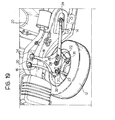
- numeral 10 generally indicates an independent suspension for a motor vehicle intended to connect a wheel 12, in this case a rear wheel, which may be either a driving wheel or a non-driving wheel, to the body 20 of the vehicle (partially illustrated in Figure 19 ).
- the suspension 10 basically comprises a longitudinal arm 14, a lateral upper rod 16 (camber control rod) and a transverse lower arm 18, all of which are rigid components, and a pair of blade-like flexible members 22 and 23 which connect the transverse lower arm 18 to a wheel carrier (per-se-known and not illustrated) of the wheel 12.
- the longitudinal arm 14 is articulated at its front end to the vehicle body 20 by means of a bush 24 and in its rear portion to the transverse arm 18 by means of a pair of bushes 26 and 28, the first one of which is arranged in an intermediate point of the longitudinal arm 14 while the second one is arranged at the rear end of this arm.
- the lateral upper rod 16 is articulated at its transversely inner end to the vehicle body 20 by means of a bush 30 and at its transversely outer end to the wheel carrier by means of a bush 32.
- the transverse lower arm 18 is articulated at the transversely inner end to the vehicle body 20 by means of a bush 34 and is connected at the transversely outer end to the wheel carrier through the two flexible blades 22 and 23.
- the flexible blades 22 and 23 are fixed at their transversely inner ends to the transverse lower arm 18 and are articulated at their transversely inner ends to the wheel carrier by means of respective bushes 36 and 37.
- one of the two flexible blades, in this case the rear blade 23 is articulated at its transversely inner end to the transverse lower arm 18 by means of the bush 37 and is fixed at its transversely outer end to the wheel carrier.
- All the above-indicated bushes are rigid, apart from the bush 26 between the longitudinal arm 14 and the transverse lower arm 18 which determines the longitudinal compliance characteristic of the suspension.
- the above-illustrated suspension architecture defines an elastic system whose behaviour under load is determined by the arrangement of two shear axes T1 and T2 ( Figures 2 and 3 ), wherein the term shear axis refers to the axis about which the elastic system has a very low rotational stiffness with respect to the other two orthogonal directions.
- a shear axis thus represents the locus of the points of highest translational stiffness with respect to forces acting on the elastic system in a direction perpendicular to the axis, since any other force not passing through this axis causes a rotation which results in a further elastic yielding of the system in the point of application of this force.
- each shear axis can be conceived as an elastic hinge of the assembly of arms and rods which connect the wheel carrier to the vehicle body.
- This elastic hinge thus defines the axis about which the wheel carrier tends to rotate with respect to the vehicle body when it is subject to an external force.
- the elastic behaviour of the suspension is defined by two shear axes acting in series with one another, in such a manner that when the wheel carrier is subject to an external force perpendicular to these two axes its displacement in due to the combination of the rotations about the two shear axes.
- the two shear axes T1 and T2 are disposed substantially in a transverse vertical plane.
- the first shear axis T1 extends substantially vertically outside the vehicle (the longitudinal middle plane of the vehicle is indicated CP), while the second shear axis T2 extends substantially horizontally, at a height comprised between the ground G and the wheel centre C.
- the horizontal shear axis T2 has a lower torsional stiffness than the one of the vertical shear axis T1.
- the second, torsionally less stiff shear axis T2 (horizontal axis) provides the required high longitudinal compliance of the wheel carrier at the wheel centre to ensure good comfort performance of the suspension.
- the torsional stiffnesses of the two shear axes are properly chosen depending on the distance of the shear axes from the wheel centre, in such a manner that the components about the vertical axis of the rotations about the two shear axes (that is to say, the components which together make up the toe change at the wheel) cancel each other out in case of an impact or traction longitudinal force IF at the wheel centre, but sum in case of a braking longitudinal force BF at the contact patch.
- the requirement for high toe-in under braking forces and at the same time for minimal toe change under traction or impact forces can be met.
- Figures 4 and 5 illustrate how the suspension architecture described above defines the two shear axes T1 and T2.
- the bushes 34 and 28 by means of which the transverse arm 18 is connected to the vehicle body and to the longitudinal arm 14, respectively, are rigid rubber bushes, whereas the bush 26 by means of which the longitudinal arm 14 is connected to the transverse arm 18 is a soft rubber bush. Accordingly, the transverse arm 18 has the possibility to rotate about the axis passing through the two bushes 34 and 28 with very little elastic resistance. This axis therefore defines the second, torsionally less stiff shear axis T2, which is orientated substantially horizontally and transversely. Since the bushes 24, 28 and 34 are all rigid bushes, this shear axis is very stiff for forces passing through the axis, but torsionally very compliant (that is, in case of forces not passing through the axis).
- the bush 26 In order to ensure the control of the elasto-kinematic characteristics of the suspension, a precise control of the torsional stiffness about the second shear axis T2 is necessary. This is achieved by virtue of the second connection between the transverse arm 18 and the longitudinal arm 14 through the bush 26.
- the sole function of the bush 26 is to adjust (via its stiffness in a roughly vertical direction) the torsional stiffness of the shear axis T2. Since the second shear axis T2 is far less stiff in rotation than the first shear axis T1, the desired longitudinal stiffness characteristic of the suspension is encapsulated in the bush 26.
- the bush 26 is subject to minimal load under the application of cornering forces, and therefore its flexibility does not compromise the necessary lateral stiffness of the suspension.
- the first, torsionally stiffer shear axis T1 is defined by the pair of blades 22, 23 on the transverse arm 18 (as shown in Figure 4 ), as it is geometrically constructed as the intersection between the planes of the two blades.
- the suspension exhibits a high ratio of the torsional stiffness about the first shear axis T1 to the translational stiffness along this axis.
- the behaviour of the suspension is such that the displacement of the wheel carrier under load is defined by the superimposed rotations about the two shear axes T1 and T2.
- the main advantage in relation to traditional suspension architectures consists in the relatively low cost, in particular if compared with the high elasto-kinematic performance offered, which basically originates from a reduction in the architecture complexity. Thanks to the great flexibility of configuration of the suspension enabled by the use of two shear axes, the elasto-kinematic performance of the suspension is in fact extremely high.
- the longitudinal flexibility of the system does not depend entirely on the bush 26 which connects the longitudinal arm 14 with the transverse arm 18, a much greater longitudinal flexibility of the wheel can be obtained without thereby reducing the lateral stiffness or passive steer capability thereof.
- the high "efficiency" of the shear axes T1 and T2 that is the high ratio of the torsional stiffness of the suspension about each axis to the translational stiffness of the suspension in response to a force passing through this axis, makes it possible for the bush 26 to have a lower lever ratio with respect to the longitudinal movement of the wheel centre. Accordingly, the bush 26 can be stiffer and more compact and can thus be manufactured as a standard radially-acting rubber bush.
- the bush 26 can incorporate a hydraulic damper.
- the proposed suspension architecture can clearly be used for driven, as well non-driven, wheels. This is due in particular to the great freedom in the positioning of the spring and the damper, enabled by the existence of two rigid lower arms (the longitudinal arm 14 and the transverse arm 18).
- the simple load paths in the suspension helps its industrialisation.
- the longitudinal arm 14 is only subject to loads in a vertical plane passing through the bushes 24, 26 and 28 and can therefore be obtained by stamping.
- the transverse arm 18 can also be easily obtained by a one- or two-piece stamping. Both these components can have a blade-like shape.
- the camber control lateral rod can be produced with any the low-cost technologies currently used for the production of such components. All the bushes, with the exception of the bush 26 which connects the longitudinal and transverse arms, can be standard rigid bushes.
- the second shear axis T2 is defined by a pair of bushes 28 and 40 which connect the longitudinal arm 14 to the transverse arm 18.
- the bush 34 between the transverse arm 18 and the vehicle body is no longer required to define the shear axis, its position can be chosen freely. Therefore, the bush 34 does not have to be aligned with the two bushes 28 and 40, as shown in Figure 6 .
- the second shear axis T2 is defined by the compliance characteristics of a flexible lower arm, generally indicated 42.
- the lower arm 42 comprises a longitudinal branch 44 and a transverse branch 48, corresponding to the longitudinal arm 14 and to the transverse arm 18, respectively, of the suspension of Figure 1 .
- the two branches 44 and 48 are formed as essentially planar elements intersecting along an axis. In this case, therefore, the axis of intersection between the two essentially planar elements 44 and 48 defines the second shear axis T2 of the suspension.
- the flexural stiffnesses of the essentially planar elements 44 and 48 can define the torsional stiffness of the suspension about the second shear axis T2.
- the second shear axis T2 is defined by a single bush 46 (or by more than one bush, according to a further non-illustrated variant of embodiment), which is mounted at the end of the longitudinal arm 14 and supports the two blades 22 and 23 which define the first shear axis T1.
- the transverse arm is here omitted and the longitudinal arm 14 has a first longitudinal branch 50 and a second oblique branch 52 articulated to the vehicle body by means of respective bushes 24 and 54.
- a third blade 25 is provided which is arranged in a plane passing through the first shear axis T1 so as to act in parallel with the first two blades 22 and 23 and is connected to the wheel carrier by means of a bush 39.
- a bush 39 it is also possible to provide a greater number of blades. It is also clear that this variant of embodiment can be combined with any one of the three variants of embodiment illustrated in Figures 6 to 8 .
- Figures 10 to 14 show further variants of embodiment of an independent suspension for a motor vehicle according to the invention, which differ from the embodiment of Figure 1 in the further links than those defining the two shear axes of the suspension.
- elements identical or corresponding to those of the suspension of Figure 1 are indicated by the same reference numerals.
- a transverse wishbone 58 articulated to the vehicle body by means of a pair of bushes 30 and to the wheel carrier of the wheel 12 by means of a bush 32, is provided instead of the transverse rod 16.
- a first rod 60 articulated by means of bushes 30 and 32 to the vehicle body and to the wheel carrier of the wheel 12, respectively, and a second rod 62, articulated to the vehicle body by means of a bush 30 and connected to the first rod 60 by means of a bush 61, are provided.
- transverse wishbone or of two rods connected to each other makes provides an additional control of the longitudinal compliance of the suspension, which predominantly affects the rotation about the second shear axis T2 for a longitudinal force though having also an effect on the rotation about the first shear axis T1.
- a link 64 is used which is articulated at its ends by means of universal joints 63 and 65 to the vehicle body and to the wheel carrier of the wheel 12, respectively, and is capable of providing a further torsional constraint about its own axis, thus contributing to the rotational stiffness of the suspension about the second shear axis T2 without however having any effect on the first shear axis T1.
- a link 66 such as the one described in the International Patent Application PCT/IB2004/001196 in the name of the Applicant is used, which is articulated at its ends by means of bushes 67 and 69 to the vehicle body and to the wheel carrier of the wheel 12, respectively.
- the link 66 also contributes to the rotational stiffness of the suspension about the transverse axis and about the vertical axis, besides constraining the translational degree of freedom along its own axis.
- the variant of embodiment illustrated in Figure 14 differs from the embodiment of Figure 1 in the addition, next to the camber control rod 16, of a toe-control lateral rod 68 which is articulated at its ends by means of bushes 71 and 73 to the vehicle body and to the wheel carrier of the wheel 12, respectively, and serves to correct the toe-out tendency of the suspension during the bump/rebound motion of the wheel in order to obtain an anti-lift effect.
- This toe-change effect due to the addition of the lateral rod 68 takes place about the first shear axis T1 defined by the blades 22 and 23. These blades have therefore to be flexible enough to absorb the deflection caused by the above effect without incurring excessive bending stresses.
- a spring and a damper which can be attached, either separately or as part of a spring and damper unit, to any of the links of the suspension or directly to the wheel carrier.
- Particularly advantageous is the mounting of the spring (indicated 38) directly onto either one of the lower arms, that is to say onto the transverse arm 18 (as shown in Figure 17 ) or onto the longitudinal arm 14 (as shown in Figure 18 ).
- the damper can also be mounted onto any of the components of the suspension, although it is preferable to mount it directly onto the wheel carrier so as to improve the damping control and reduce the stresses on the component during operation.
- the rotational stiffness about the first shear axis T1 can be controlled by means of:
- the rotational stiffness about the second shear axis T2 can be controlled by means of:
Landscapes
- Engineering & Computer Science (AREA)
- Mechanical Engineering (AREA)
- Vehicle Body Suspensions (AREA)
- Arrangement Or Mounting Of Propulsion Units For Vehicles (AREA)
- Vibration Prevention Devices (AREA)
Abstract
Description
- The present invention relates to an independent suspension for a motor vehicle, as defined in the preamble of Claim 1.
- European Patent Application
EP-A-1 288 028 in the name of the Applicant discloses a suspension essentially comprising a transverse arm, a transverse rod and a camber control rod, each interposed between a wheel carrier and the vehicle body. Specifically, the transverse arm comprises a pair of blade-like flexible elements, which are articulated at their ends to the wheel carrier and to the vehicle body and are connected to each other by means of a torsionally stiff, longitudinal tubular element. Firstly, the transverse arm controls two kinematics degrees of freedom of rotation about first and second substantially longitudinal axes, defined by the points of articulation to the wheel carrier and to the vehicle structure. Moreover, the flexibility, the configuration and the orientation of the two blades of the transverse arm are chosen in such a manner that the wheel carrier is capable of rotating about a third axis of predetermined orientation (referred to as "shear axis"), as a result of the deformation of the two blades about that axis. The transverse arm is therefore capable of controlling a third rotational degree of freedom of the wheel carrier about the shear axis. This third degree of freedom is defined as a "structural" degree of freedom since, contrary to the other two rotational degrees of freedom, it is not defined by a geometrical constraint but by the inherent flexibility of the components of the arm with respect to the shear axis. In order to achieve the best compromise between the opposite requirements for insulation of the occupants of the vehicle from the unevenness of the road and for effective and prompt response to the forces acting on the wheels, in particular to the steering and braking forces, this third axis is preferably chosen to pass in the vicinity of the contact patch of the tyre. - A motor-vehicle independent suspension according to the preamble of Claim I is known from European Patent Application
EP-A-1 361 084 in the name of the Applicant. According to this document, the suspension comprises a wheel-carrier, a lower transverse arm articulated at the one end to the vehicle body by means of a pair of bushes and at the other end to the wheel-carrier by means of a pair of bushes, and an upper transverse arm articulated at the one end to the vehicle body by means of a bush and at the other end to the wheel-carrier by means of a bush. The wheel-carrier includes two blade-like flexible members intersecting along a common axis which is inclined with regards to a horizontal plane and defines a shear axis of the suspension. - It is the object of the present invention to provide an independent suspension for a motor vehicle which has a better elasto-kinematic behaviour, which has more compact sizes and which is easier to install on different motor-vehicles models than the prior art.
- This and other objects are achieved according to the invention by virtue of an independent suspension for a motor vehicle having the characteristics set forth in independent Claim 1.
- Further advantageous characteristics of the invention are specified in the dependent Claims.
- To summarise, the invention is based on the idea of providing an independent suspension for a motor vehicle which, by virtue of the arrangement and the stiffness characteristics of its components, forms an elastic system having two shear axes of predetermined orientation arranged so as to act in series with one another, one of these axes being defined by a pair of blade-like flexible elements.
- Preferably, the two shear axes are disposed in a transverse vertical plane and are orientated perpendicular to each other, wherein the first shear axis is arranged substantially vertically while the second shear axis arranged substantially horizontally, the torsional stiffness of the elastic system about the second, substantially horizontal shear axis being less than the one about the first, substantially vertical shear axis.
- The characteristics and the advantages of the present invention will become apparent from the detailed description which follows, given purely by way of non-limiting example with reference to the appended drawings, in which:
-
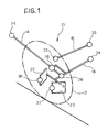
Figure 1 is a schematic illustration of an independent suspension for a motor vehicle according to a preferred embodiment of the present invention; -
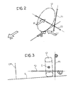
Figures 2 and 3 are perspective and front elevation schematic illustrations, respectively, which show the positioning of the two shear axes of the suspension ofFigure 1 ; -
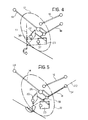
Figure 4 is a schematic illustration similar to that ofFigure 1 , which shows in particular the construction of the first shear axis of the suspension; -
Figure 5 is a schematic illustration similar to that ofFigure 1 , which shows in particular the construction of the second shear axis of the suspension; -
Figures 6 to 8 are schematic illustrations each showing a variant of embodiment of an independent suspension for a motor vehicle according to the invention which differs from the embodiment ofFigure 1 in the way of realisation of the second shear axis; -
Figure 9 is a schematic illustration of a variant of embodiment of an independent suspension for a motor vehicle according to the invention which differs from the embodiment ofFigure 1 in the way of realisation of the first shear axis; -
Figures 10 to 14 are schematic illustrations each showing a variant of embodiment on an independent suspension for a motor vehicle according to the invention which differs from the embodiment ofFigure 1 in the further links than those which define the two shear axes of the suspension; -
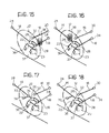
Figures 15 and 16 are schematic illustrations each showing a possible arrangement of the spring in the suspension according to the embodiment ofFigure 1 ; -
Figures 17 and 18 are schematic illustrations each showing a further variant of embodiment of an independent suspension for a motor vehicle according to the invention; and -
Figure 19 is a perspective view from below which shows a variant of embodiment of the invention intended for a rear suspension of a motor vehicle. - In the description and the claims which follow, terms such as "longitudinal" and "transverse", "vertical" and "horizontal", "front" and "rear" are to be intended as referred to the mounted condition on the vehicle.
- By referring first to
Figures 1 and19 ,numeral 10 generally indicates an independent suspension for a motor vehicle intended to connect awheel 12, in this case a rear wheel, which may be either a driving wheel or a non-driving wheel, to thebody 20 of the vehicle (partially illustrated inFigure 19 ). Thesuspension 10 basically comprises alongitudinal arm 14, a lateral upper rod 16 (camber control rod) and a transverselower arm 18, all of which are rigid components, and a pair of blade-likeflexible members lower arm 18 to a wheel carrier (per-se-known and not illustrated) of thewheel 12. - The
longitudinal arm 14 is articulated at its front end to thevehicle body 20 by means of abush 24 and in its rear portion to thetransverse arm 18 by means of a pair ofbushes longitudinal arm 14 while the second one is arranged at the rear end of this arm. The lateralupper rod 16 is articulated at its transversely inner end to thevehicle body 20 by means of abush 30 and at its transversely outer end to the wheel carrier by means of abush 32. The transverselower arm 18 is articulated at the transversely inner end to thevehicle body 20 by means of abush 34 and is connected at the transversely outer end to the wheel carrier through the twoflexible blades Figure 1 theflexible blades lower arm 18 and are articulated at their transversely inner ends to the wheel carrier by means ofrespective bushes Figure 19 , on the other hand, one of the two flexible blades, in this case therear blade 23, is articulated at its transversely inner end to the transverselower arm 18 by means of thebush 37 and is fixed at its transversely outer end to the wheel carrier. - All the above-indicated bushes are rigid, apart from the
bush 26 between thelongitudinal arm 14 and the transverselower arm 18 which determines the longitudinal compliance characteristic of the suspension. - The above-illustrated suspension architecture defines an elastic system whose behaviour under load is determined by the arrangement of two shear axes T1 and T2 (
Figures 2 and 3 ), wherein the term shear axis refers to the axis about which the elastic system has a very low rotational stiffness with respect to the other two orthogonal directions. A shear axis thus represents the locus of the points of highest translational stiffness with respect to forces acting on the elastic system in a direction perpendicular to the axis, since any other force not passing through this axis causes a rotation which results in a further elastic yielding of the system in the point of application of this force. - In other words, each shear axis can be conceived as an elastic hinge of the assembly of arms and rods which connect the wheel carrier to the vehicle body. This elastic hinge thus defines the axis about which the wheel carrier tends to rotate with respect to the vehicle body when it is subject to an external force. In the present case, the elastic behaviour of the suspension is defined by two shear axes acting in series with one another, in such a manner that when the wheel carrier is subject to an external force perpendicular to these two axes its displacement in due to the combination of the rotations about the two shear axes.
- With reference in particular to
Figures 2 and 3 , in the embodiment illustrated herein (which is intended to a rear suspension of a motor vehicle, as mentioned above) the two shear axes T1 and T2 are disposed substantially in a transverse vertical plane. The first shear axis T1 extends substantially vertically outside the vehicle (the longitudinal middle plane of the vehicle is indicated CP), while the second shear axis T2 extends substantially horizontally, at a height comprised between the ground G and the wheel centre C. The horizontal shear axis T2 has a lower torsional stiffness than the one of the vertical shear axis T1. This means that a force which is directed perpendicularly to the plane defined by the two shear axes T1 and T2 and is applied to the wheel carrier in a point equidistant from these axes causes a smaller angular displacement about the axis T1 than the one about the axis T2. However, also in this case the resulting displacement of the wheel carrier will be the sum of these two angular displacements. - The special arrangement of the two shear axes T1 and T2 shown in
Figures 2 and 3 meets the elasto-kinematic requirements of the suspension in the following way. - Firstly, the second, torsionally less stiff shear axis T2 (horizontal axis) provides the required high longitudinal compliance of the wheel carrier at the wheel centre to ensure good comfort performance of the suspension.
- Secondly, the torsional stiffnesses of the two shear axes are properly chosen depending on the distance of the shear axes from the wheel centre, in such a manner that the components about the vertical axis of the rotations about the two shear axes (that is to say, the components which together make up the toe change at the wheel) cancel each other out in case of an impact or traction longitudinal force IF at the wheel centre, but sum in case of a braking longitudinal force BF at the contact patch. In this way, the requirement for high toe-in under braking forces and at the same time for minimal toe change under traction or impact forces can be met.
- It is however possible, with a suspension according to the invention, meet other requirements than those indicated above by properly defining from time to time the orientation of the two shear axes.
- Thirdly, by virtue of the torsionally stiffer, vertical shear axis T1 being arranged behind the contact patch with respect to the driving direction of the vehicle (indicated SM in
Figure 2 ), a toe-in effect under steering forces (indicated CF inFigure 2 ) is obtained. Since the second shear axis T2 is substantially parallel to the steering forces, its presence does not significantly reduce the available lateral stiffness at the contact patch. Provided that the first shear axis T1 is not placed too far from the contact patch of the wheel (for example at a distance of 80 to 100 mm) and has a torsional stiffness suitable for providing the required toe change under steering forces, then the wheel carrier will exhibit the required high lateral stiffness at the contact patch. -
Figures 4 and 5 illustrate how the suspension architecture described above defines the two shear axes T1 and T2. - The
bushes transverse arm 18 is connected to the vehicle body and to thelongitudinal arm 14, respectively, are rigid rubber bushes, whereas thebush 26 by means of which thelongitudinal arm 14 is connected to thetransverse arm 18 is a soft rubber bush. Accordingly, thetransverse arm 18 has the possibility to rotate about the axis passing through the twobushes bushes - In order to ensure the control of the elasto-kinematic characteristics of the suspension, a precise control of the torsional stiffness about the second shear axis T2 is necessary. This is achieved by virtue of the second connection between the
transverse arm 18 and thelongitudinal arm 14 through thebush 26. The sole function of thebush 26 is to adjust (via its stiffness in a roughly vertical direction) the torsional stiffness of the shear axis T2. Since the second shear axis T2 is far less stiff in rotation than the first shear axis T1, the desired longitudinal stiffness characteristic of the suspension is encapsulated in thebush 26. Moreover, thebush 26 is subject to minimal load under the application of cornering forces, and therefore its flexibility does not compromise the necessary lateral stiffness of the suspension. - The first, torsionally stiffer shear axis T1 is defined by the pair of
blades Figure 4 ), as it is geometrically constructed as the intersection between the planes of the two blades. By properly choosing the orientation of the twoblades bushes blades - As mentioned above, the behaviour of the suspension is such that the displacement of the wheel carrier under load is defined by the superimposed rotations about the two shear axes T1 and T2. The more the
camber control rod 16 is arranged approximately parallel to the second shear axis T2 and passes through the first shear axis T1, the more is this concept valid. - Having regard to the forces acting on the suspension, it is to be noticed that the longitudinal behaviour of the suspension at the wheel carrier is well decoupled from its lateral behaviour. The cornering forces do not pass through the
soft bush 26 and, apart from the torsional compliance about the vertical direction (provided by the first shear axis T1) necessary to produce the desired toe-in effect under cornering forces, there are no other parasitic compliances capable of lowering the lateral stiffness at the contact patch. - The main advantages of an independent suspension according to the invention will be now illustrated.
- First of all, the main advantage in relation to traditional suspension architectures consists in the relatively low cost, in particular if compared with the high elasto-kinematic performance offered, which basically originates from a reduction in the architecture complexity. Thanks to the great flexibility of configuration of the suspension enabled by the use of two shear axes, the elasto-kinematic performance of the suspension is in fact extremely high.
- Since the longitudinal flexibility of the system does not depend entirely on the
bush 26 which connects thelongitudinal arm 14 with thetransverse arm 18, a much greater longitudinal flexibility of the wheel can be obtained without thereby reducing the lateral stiffness or passive steer capability thereof. The high "efficiency" of the shear axes T1 and T2, that is the high ratio of the torsional stiffness of the suspension about each axis to the translational stiffness of the suspension in response to a force passing through this axis, makes it possible for thebush 26 to have a lower lever ratio with respect to the longitudinal movement of the wheel centre. Accordingly, thebush 26 can be stiffer and more compact and can thus be manufactured as a standard radially-acting rubber bush. Advantageously, thebush 26 can incorporate a hydraulic damper. - The high decoupling of the longitudinal loads from the lateral loads, and therefore the high decoupling of the elasto-kinematic characteristics of the suspension, makes vehicle development quicker and easier. Moreover, the unsprung mass of the vehicle is reduced with this architecture.
- As far as the installation on the vehicle is concerned, the fact that the suspension uses a mounting location to the vehicle body (the
bush 24 which connects thelongitudinal arm 14 to the vehicle body) common to the vast majority of small-to-medium size passenger cars, which generally adopt rear suspensions having a twist-beam or longitudinal guided arms, involves minimal modifications to the vehicle structure for the installation of the suspension on existing platforms. - The proposed suspension architecture can clearly be used for driven, as well non-driven, wheels. This is due in particular to the great freedom in the positioning of the spring and the damper, enabled by the existence of two rigid lower arms (the
longitudinal arm 14 and the transverse arm 18). - The simple load paths in the suspension helps its industrialisation. For instance, the
longitudinal arm 14 is only subject to loads in a vertical plane passing through thebushes transverse arm 18 can also be easily obtained by a one- or two-piece stamping. Both these components can have a blade-like shape. The camber control lateral rod can be produced with any the low-cost technologies currently used for the production of such components. All the bushes, with the exception of thebush 26 which connects the longitudinal and transverse arms, can be standard rigid bushes. - The provision of three mounting points of the wheel carrier to the suspension makes the assembly and camber/toe static set-up processes easier.
- Finally, the use of short flexible blades increases the resistance to collapse under lateral abuse loads due to buckling.
- Three possible variants of embodiment of an independent suspension for a motor vehicle according to the invention, which differ from the preferred embodiment described above in the way of realisation of the second shear axis T2 (horizontal axis), are illustrated in
Figures 6 to 8 , in which parts and elements identical or corresponding to those of the preceding figures have been given the same reference numerals. - In the suspension shown in
Figure 6 the second shear axis T2 is defined by a pair ofbushes longitudinal arm 14 to thetransverse arm 18. In this case, since thebush 34 between thetransverse arm 18 and the vehicle body is no longer required to define the shear axis, its position can be chosen freely. Therefore, thebush 34 does not have to be aligned with the twobushes Figure 6 . - In the suspension shown in
Figure 7 the second shear axis T2 is defined by the compliance characteristics of a flexible lower arm, generally indicated 42. Thelower arm 42 comprises alongitudinal branch 44 and atransverse branch 48, corresponding to thelongitudinal arm 14 and to thetransverse arm 18, respectively, of the suspension ofFigure 1 . In the particular embodiment illustrated inFigure 7 the twobranches planar elements planar elements - In the suspension shown in
Figure 8 the second shear axis T2 is defined by a single bush 46 (or by more than one bush, according to a further non-illustrated variant of embodiment), which is mounted at the end of thelongitudinal arm 14 and supports the twoblades longitudinal arm 14 has a firstlongitudinal branch 50 and asecond oblique branch 52 articulated to the vehicle body by means ofrespective bushes - Another possible variant of embodiment of an independent suspension for a motor vehicle according to the invention, which differs from the preferred embodiment previously described in the way of realisation of the first shear axis T1, is illustrated in
Figure 9 , in which parts and elements identical or corresponding to those of the preceding figures have been given the same reference numerals. - According to this variant of embodiment, a
third blade 25 is provided which is arranged in a plane passing through the first shear axis T1 so as to act in parallel with the first twoblades bush 39. Clearly, it is also possible to provide a greater number of blades. It is also clear that this variant of embodiment can be combined with any one of the three variants of embodiment illustrated inFigures 6 to 8 . -
Figures 10 to 14 show further variants of embodiment of an independent suspension for a motor vehicle according to the invention, which differ from the embodiment ofFigure 1 in the further links than those defining the two shear axes of the suspension. In these figures, elements identical or corresponding to those of the suspension ofFigure 1 are indicated by the same reference numerals. - In the variant of embodiment of
Figure 10 atransverse wishbone 58, articulated to the vehicle body by means of a pair ofbushes 30 and to the wheel carrier of thewheel 12 by means of abush 32, is provided instead of thetransverse rod 16. In the variant of embodiment ofFigure 11 a first rod 60, articulated by means ofbushes wheel 12, respectively, and asecond rod 62, articulated to the vehicle body by means of abush 30 and connected to the first rod 60 by means of abush 61, are provided. The use of a transverse wishbone or of two rods connected to each other makes provides an additional control of the longitudinal compliance of the suspension, which predominantly affects the rotation about the second shear axis T2 for a longitudinal force though having also an effect on the rotation about the first shear axis T1. - The two variants of embodiment illustrated in
Figure 12 and inFigure 13 provides for the use of links which also control torsional degrees of freedom in addition to the usual translational degree of freedom. In the example ofFigure 12 a link 64 is used which is articulated at its ends by means ofuniversal joints wheel 12, respectively, and is capable of providing a further torsional constraint about its own axis, thus contributing to the rotational stiffness of the suspension about the second shear axis T2 without however having any effect on the first shear axis T1. In the example ofFigure 13 alink 66 such as the one described in the International Patent ApplicationPCT/IB2004/001196 bushes wheel 12, respectively. Thelink 66 also contributes to the rotational stiffness of the suspension about the transverse axis and about the vertical axis, besides constraining the translational degree of freedom along its own axis. - The variant of embodiment illustrated in
Figure 14 differs from the embodiment ofFigure 1 in the addition, next to thecamber control rod 16, of a toe-control lateral rod 68 which is articulated at its ends by means ofbushes 71 and 73 to the vehicle body and to the wheel carrier of thewheel 12, respectively, and serves to correct the toe-out tendency of the suspension during the bump/rebound motion of the wheel in order to obtain an anti-lift effect. This toe-change effect due to the addition of thelateral rod 68 takes place about the first shear axis T1 defined by theblades - In the suspension of the invention there are no limitations on the placing of a spring and a damper, which can be attached, either separately or as part of a spring and damper unit, to any of the links of the suspension or directly to the wheel carrier. Particularly advantageous is the mounting of the spring (indicated 38) directly onto either one of the lower arms, that is to say onto the transverse arm 18 (as shown in
Figure 17 ) or onto the longitudinal arm 14 (as shown inFigure 18 ). The damper can also be mounted onto any of the components of the suspension, although it is preferable to mount it directly onto the wheel carrier so as to improve the damping control and reduce the stresses on the component during operation. - The different ways in which the rotational stiffnesses of the suspension about the two shear axes can be controlled are listed below.
- The rotational stiffness about the first shear axis T1 can be controlled by means of:
- a) the flexural stiffnesses of the flexible blades (the two
blades Figure 1 andFigures 6 to 8 and the threeblades Figure 9 ); or - b) an additional connection of the wheel carrier to one of the two lower arms (the
longitudinal arm 14 in the variants of embodiment illustrated inFigures 17 and 18 ), obtained either directly with a bush 70 (Figure 17 ) or with a proper link 72 (Figure 18 ) articulated at an end to the wheel carrier by means of abush 74 and at the opposite end to thelongitudinal arm 14 by means of abush 76. - The rotational stiffness about the second shear axis T2 can be controlled by means of:
- a) an additional bush between the
longitudinal arm 14 and thetransverse arm 18, such as for example thebush 26 of the embodiment ofFigure 1 ; - b) the torsional stiffness of the bushes which define the second shear axis T2, that is to say the
bushes Figure 1 , thebushes Figure 6 and thebush 46 in the embodiment ofFigure 8 ; - c) a longitudinal constraint applied to the wheel carrier, such as for example the one provided by the
transverse wishbone 58 in the embodiment ofFigure 12 or by the twointerconnected rods 60 and 62 in the embodiment ofFigure 11 ; or - d) the flexural stiffness of the flexible
lower arm 42 in the embodiment ofFigure 7 . - Naturally, the principle of the invention remaining unchanged, embodiments and manufacturing details can be varied widely from those described and illustrated purely by way of non-limiting example.
Claims (19)
- Motor-vehicle independent suspension for connecting a wheel carrier of a vehicle wheel (12) to a vehicle body (20), the suspension comprising at least one lower arm (14, 18; 42, 44, 48; 14, 50, 52) connected (24, 34; 24, 54) to the vehicle body (20) and at least one upper link (16; 58; 60, 62; 64; 66; 16, 68) connected (30; 63; 67; 30,71) to the vehicle body (20),
wherein said at least one lower arm (14, 18; 42, 44, 48; 14, 50, 52) carries at least two substantially blade-like flexible members (22, 23; 22, 23, 25) which are connected (36, 37; 36, 37, 39) to the wheel carrier of the wheel (12) and the planes of which intersect along one common axis (T1) of predetermined orientation defining a first shear axis of the suspension, and
wherein said at least one lower arm (14, 18; 42, 44, 48; 14, 50, 52) is connected to the vehicle body (20) by means of a pair of bushes (24, 34; 24, 54), namely a first bush (24) and a second bush (34; 54),
the suspension being characterized in that
said at least one lower arm (14, 18; 42, 44, 48; 14, 50, 52) is configured to define a second shear axis (T2) of predetermined orientation acting in series with the first axis (T1), in such a manner that when the wheel carrier is subject to an external force acting in a substantially horizontal plane the displacement of the wheel carrier results from the combination of the rotations of the wheel carrier about the two shear axes (T1, T2), and in that
said at least one lower arm (14, 18; 42, 44, 48; 14, 50, 52) includes a longitudinal arm (14; 44; 50) connected to the vehicle body (20) by means of the first bush (24). - Suspension according to Claim 1, wherein the two shear axes (T1, T2) are arranged substantially in a transverse vertical plane.
- Suspension according to Claim 2, wherein the first shear axis (T1) extends substantially vertically outside the vehicle and the second shear axis (T2) extends substantially horizontally at a height comprised between the ground (G) and the centre (C) of the wheel (12).
- Suspension according to Claim 3, having a higher torsional stiffness about the first shear axis (T1) than the torsional stiffness about the second shear axis (T2).
- Suspension according to any of the preceding claims, comprising a rigid lower longitudinal arm (14) and a lower transverse arm (18) to which the said at least two blade-like flexible members (22, 23; 22, 23, 25) are connected.
- Suspension according to Claim 5, wherein the longitudinal arm (14) is articulated to the transverse arm (18) by means of a third soft bush (26) arranged in an intermediate portion of the longitudinal arm (14) and by means of a fourth rigid bush (28) arranged at an end of this arm (14), and wherein the transverse arm (18) is also articulated to the vehicle body by means of said second bush (34) made as a rigid bush, in such a manner that the second shear axis (T2) corresponds to the axis passing through the second and fourth bushes (34, 28).
- Suspension according to Claim 5, wherein the longitudinal arm (14) is articulated to the transverse arm (18) by means of a pair of rigid bushes (28, 40), in such a manner that the axis passing through said pair of bushes (28, 40) corresponds to the second shear axis (T2).
- Suspension according to Claim 1, comprising a single lower arm (42) including a flexible longitudinal branch (44) and a flexible transverse branch (48) formed as essentially planar elements which intersect along an axis, in such a manner that the second shear axis (T2) of the suspension corresponds to the axis of intersection between the said essentially planar elements (44, 48).
- Suspension according to Claim 1, comprising
a single lower arm (14) having a first longitudinal branch (50) and a second oblique branch (52) articulated to the vehicle body by means of said first and second bushes (24, 54), respectively, and
at least one bush (46) which is mounted onto the lower arm (14) and supports said at least two blade-like flexible members (22, 23; 22, 23, 25). - Suspension according to any of the preceding claims, wherein said at least one upper link is a camber control lateral rod (16) articulated to the vehicle body and to the wheel carrier of the wheel (12) by means of respective bushes (30, 32).
- Suspension according to Claim 10, wherein the lateral rod (16) is approximately parallel to the second shear axis (T2) and passes through the first shear axis (T1).
- Suspension according to any of Claims 1 to 9, wherein said at least one upper link is a transverse wishbone (58), which is articulated to the vehicle body by means of a pair of bushes (30) and to the wheel carrier of the wheel (12) by means of a single bush (32).
- Suspension according to any of Claims 1 to 9, wherein said at least one upper link comprises a first rod (60) which is articulated by means of bushes (30, 32) to the vehicle body and to the wheel carrier of the wheel (12), respectively, and a second rod (62) which is articulated to the vehicle body by means of a bush (30) and is connected to the first rod (60) by means of a bush (61).
- Suspension according to any of Claims 1 to 9, wherein said at least one upper link is a rod (64; 66) which is articulated by means of bushes (63, 65; 67, 69) to the vehicle body and to the wheel carrier of the wheel (12), respectively, and is capable of controlling both a translational degree of freedom along its own axis and at least one rotational degree of freedom.
- Suspension according to Claim 10, wherein said at least one upper link further comprises a toe-control lateral rod (68), which is articulated by means of bushes (71, 73) to the vehicle body and to the wheel carrier of the wheel (12), respectively.
- Suspension according to any of the preceding claims, further comprising a spring (38) mounted onto said at least one lower arm (18; 14).
- Suspension according to any of the preceding claims, wherein said at least one lower arm (14) is connected to the wheel carrier either directly with a bush (70) or with a link (72) articulated (74, 76) at its ends to the lower arm (14) and to the wheel carrier.
- Suspension according to any of Claims 1 to 8, wherein said at least two blade-like flexible members (22, 23; 22, 23, 25) are articulated at their transversely outer ends to the wheel carrier of the wheel (12) by means of respective bushes (36, 37; 36, 37, 39) and are attached at their transversely inner ends to said at least one lower arm (18; 42).
- Suspension according to any of Claims 1 to 8, comprising two blade-like flexible members (22, 23), of which the one (22) is articulated at its transversely cuter end to the wheel carrier of the wheel (12) by means of a bush (36) and is attached at its transversely inner end to said at least one lower arm (18), and the other (23) is attached at its transversely outer end to the wheel carrier of the wheel (12) and is articulated at its transversely inner end to said at least one lower arm (18) by means of a bush (37).
Applications Claiming Priority (2)
| Application Number | Priority Date | Filing Date | Title |
|---|---|---|---|
| IT000861A ITTO20040861A1 (en) | 2004-12-09 | 2004-12-09 | SUSPENSION WITH INDEPENDENT WHEELS FOR MOTOR VEHICLES |
| PCT/EP2005/056518 WO2006061383A1 (en) | 2004-12-09 | 2005-12-06 | Independent suspension for a motor vehicle |
Publications (2)
| Publication Number | Publication Date |
|---|---|
| EP1827878A1 EP1827878A1 (en) | 2007-09-05 |
| EP1827878B1 true EP1827878B1 (en) | 2008-12-17 |
Family
ID=35708663
Family Applications (1)
| Application Number | Title | Priority Date | Filing Date |
|---|---|---|---|
| EP05813644A Expired - Lifetime EP1827878B1 (en) | 2004-12-09 | 2005-12-06 | Independent suspension for a motor vehicle |
Country Status (10)
| Country | Link |
|---|---|
| US (1) | US7823894B2 (en) |
| EP (1) | EP1827878B1 (en) |
| JP (1) | JP4805276B2 (en) |
| AT (1) | ATE417747T1 (en) |
| BR (1) | BRPI0517145A (en) |
| DE (1) | DE602005011853D1 (en) |
| ES (1) | ES2319677T3 (en) |
| IT (1) | ITTO20040861A1 (en) |
| RU (1) | RU2408474C2 (en) |
| WO (1) | WO2006061383A1 (en) |
Families Citing this family (12)
| Publication number | Priority date | Publication date | Assignee | Title |
|---|---|---|---|---|
| FR2908081B1 (en) * | 2006-11-06 | 2008-12-12 | Peugeot Citroen Automobiles Sa | MOTOR VEHICLE REAR AXLE TRAIN |
| FR2909310B1 (en) * | 2006-12-05 | 2008-12-26 | Peugeot Citroen Automobiles Sa | RIGID AXLE TYPE REAR AXLE |
| JP2008195296A (en) * | 2007-02-14 | 2008-08-28 | Honda Motor Co Ltd | Suspension device |
| JP5205797B2 (en) * | 2007-04-27 | 2013-06-05 | 日産自動車株式会社 | Suspension device |
| FR2926248B1 (en) * | 2008-01-16 | 2011-11-04 | Peugeot Citroen Automobiles Sa | UNDER VEHICLE ROLLER ASSEMBLY |
| IT1391870B1 (en) * | 2008-11-12 | 2012-01-27 | Sistemi Sospensioni Spa | SUSPENSION WITH INDEPENDENT WHEELS FOR VEHICLE |
| JP5005067B2 (en) * | 2010-05-28 | 2012-08-22 | 本田技研工業株式会社 | Suspension device |
| JP5163800B2 (en) * | 2011-10-24 | 2013-03-13 | 日産自動車株式会社 | Suspension device |
| DE102012220490A1 (en) * | 2011-11-11 | 2013-05-16 | Ford Global Technologies, Llc | Independent rear suspension of a motor vehicle |
| US9469173B2 (en) * | 2011-11-14 | 2016-10-18 | Gordon Murray Design Limited | Vehicle suspension |
| DE102012217271A1 (en) * | 2012-09-25 | 2014-05-28 | Bayerische Motoren Werke Aktiengesellschaft | Independent suspension of a wheel of a two-lane vehicle with a spring element |
| ITUB20153561A1 (en) * | 2015-09-11 | 2017-03-11 | Fca Italy Spa | "Suspension of rear wheel of motor vehicle, with independent wheels" |
Family Cites Families (15)
| Publication number | Priority date | Publication date | Assignee | Title |
|---|---|---|---|---|
| SU370084A1 (en) * | 1967-05-23 | 1973-02-15 | INDEPENDENT LEVER SUSPENSION TRANSPORT | |
| DE2142523C3 (en) * | 1971-08-25 | 1974-03-28 | Daimler-Benz Ag, 7000 Stuttgart | Wheel suspension, in particular front wheel suspension for motor vehicles |
| DE3048755C2 (en) * | 1980-12-23 | 1983-03-10 | Daimler-Benz Ag, 7000 Stuttgart | Independent wheel suspension for motor vehicles |
| US4753456A (en) * | 1983-08-22 | 1988-06-28 | Booher Benjamin V | Vehicle suspension system with flexible control arm |
| JPH01190511A (en) * | 1988-01-26 | 1989-07-31 | Mazda Motor Corp | Vehicle suspension device |
| JP2518349B2 (en) * | 1988-04-19 | 1996-07-24 | トヨタ自動車株式会社 | Rear suspension for vehicles |
| JPH0237008A (en) * | 1988-07-27 | 1990-02-07 | Mazda Motor Corp | Suspension device |
| US5080388A (en) * | 1990-05-18 | 1992-01-14 | Specialty Products, Inc. | Wheel alignment adjustment device |
| JPH06336107A (en) * | 1991-01-31 | 1994-12-06 | Mazda Motor Corp | Vehicle suspension system |
| JP2002012015A (en) | 2000-04-27 | 2002-01-15 | Nissan Motor Co Ltd | Suspension device |
| RU2225796C2 (en) * | 2001-01-30 | 2004-03-20 | Общество с ограниченной ответственностью Проектно-производственная фирма "Автодизайн" | Independent suspension of vehicle steerable wheels |
| ITTO20010843A1 (en) * | 2001-09-03 | 2003-03-03 | Sistemi Sospensioni Spa | ARM FOR AN AUTOMOTIVE SUSPENSION WITH INDEPENDENT WHEELS AND AUTOMOTIVE SUSPENSION WITH INDEPENDENT WHEELS INCLUDING SUCH ARMS |
| ITTO20020397A1 (en) * | 2002-05-10 | 2003-11-10 | Sistemi Sospensioni Spa | SUPPORT STRUCTURE FOR A WHEEL HOLDER OF A VEHICLE. |
| RU2238192C2 (en) * | 2002-07-09 | 2004-10-20 | Общество с ограниченной ответственностью Проектно-производственная фирма "Автодизайн" | Car steerable wheel independent suspension |
| FR2861333B1 (en) | 2003-10-28 | 2007-01-26 | Peugeot Citroen Automobiles Sa | SEMI-DEFORMABLE REAR TRAIN WITH LONGITUDINAL FLEXIBILITY. |
-
2004
- 2004-12-09 IT IT000861A patent/ITTO20040861A1/en unknown
-
2005
- 2005-12-06 RU RU2007125678/11A patent/RU2408474C2/en active
- 2005-12-06 EP EP05813644A patent/EP1827878B1/en not_active Expired - Lifetime
- 2005-12-06 BR BRPI0517145-8A patent/BRPI0517145A/en not_active IP Right Cessation
- 2005-12-06 AT AT05813644T patent/ATE417747T1/en not_active IP Right Cessation
- 2005-12-06 DE DE602005011853T patent/DE602005011853D1/en not_active Expired - Lifetime
- 2005-12-06 JP JP2007544901A patent/JP4805276B2/en not_active Expired - Fee Related
- 2005-12-06 WO PCT/EP2005/056518 patent/WO2006061383A1/en not_active Ceased
- 2005-12-06 US US11/720,966 patent/US7823894B2/en active Active
- 2005-12-06 ES ES05813644T patent/ES2319677T3/en not_active Expired - Lifetime
Also Published As
| Publication number | Publication date |
|---|---|
| ITTO20040861A1 (en) | 2005-03-09 |
| JP4805276B2 (en) | 2011-11-02 |
| BRPI0517145A (en) | 2008-09-30 |
| RU2007125678A (en) | 2009-01-20 |
| JP2008522892A (en) | 2008-07-03 |
| EP1827878A1 (en) | 2007-09-05 |
| WO2006061383A1 (en) | 2006-06-15 |
| US7823894B2 (en) | 2010-11-02 |
| US20080079233A1 (en) | 2008-04-03 |
| RU2408474C2 (en) | 2011-01-10 |
| ATE417747T1 (en) | 2009-01-15 |
| DE602005011853D1 (en) | 2009-01-29 |
| ES2319677T3 (en) | 2009-05-11 |
Similar Documents
| Publication | Publication Date | Title |
|---|---|---|
| EP2355987B1 (en) | Vehicle independent suspension | |
| EP0872367B1 (en) | Vehicle rear suspension apparatus | |
| US8523209B2 (en) | Semi-trailing arm axle for a motor vehicle | |
| KR100319580B1 (en) | Front suspension | |
| EP1288028B1 (en) | A wheel suspension arm and a motor-vehicle independent suspension system comprising the arm | |
| US7823894B2 (en) | Independent suspension for a motor vehicle | |
| KR101461902B1 (en) | Coupled torsion beam axle type suspension system | |
| JP2022154817A (en) | Suspension device of automobile | |
| EP2021195B1 (en) | An arm for a motor vehicle independent suspension and motor vehicle independent suspension comprising the same | |
| JPH05162518A (en) | Vehicle suspension system | |
| KR100310431B1 (en) | Front suspension of motor vehicle | |
| EP3643542B1 (en) | Wheel suspension system for the front axle of motor vehicles | |
| EP1829717B1 (en) | Mounting structure for a wheel carrier of a motor vehicle | |
| US8419030B2 (en) | Rear wheel suspension system for motor vehicles | |
| JP2003146038A (en) | Suspension device | |
| JP3105073B2 (en) | Vehicle suspension device | |
| JP2000043529A (en) | Front suspension device | |
| KR19980083530A (en) | Car Stabilizer | |
| BRPI0517145B1 (en) | INDEPENDENT SUSPENSION FOR A MOTORIZED VEHICLE |
Legal Events
| Date | Code | Title | Description |
|---|---|---|---|
| PUAI | Public reference made under article 153(3) epc to a published international application that has entered the european phase |
Free format text: ORIGINAL CODE: 0009012 |
|
| 17P | Request for examination filed |
Effective date: 20070709 |
|
| AK | Designated contracting states |
Kind code of ref document: A1 Designated state(s): AT BE BG CH CY CZ DE DK EE ES FI FR GB GR HU IE IS IT LI LT LU LV MC NL PL PT RO SE SI SK TR |
|
| 17Q | First examination report despatched |
Effective date: 20070905 |
|
| RIN1 | Information on inventor provided before grant (corrected) |
Inventor name: GERRARD, MILES, BARNABY |
|
| DAX | Request for extension of the european patent (deleted) | ||
| GRAP | Despatch of communication of intention to grant a patent |
Free format text: ORIGINAL CODE: EPIDOSNIGR1 |
|
| GRAS | Grant fee paid |
Free format text: ORIGINAL CODE: EPIDOSNIGR3 |
|
| GRAA | (expected) grant |
Free format text: ORIGINAL CODE: 0009210 |
|
| AK | Designated contracting states |
Kind code of ref document: B1 Designated state(s): AT BE BG CH CY CZ DE DK EE ES FI FR GB GR HU IE IS IT LI LT LU LV MC NL PL PT RO SE SI SK TR |
|
| REG | Reference to a national code |
Ref country code: GB Ref legal event code: FG4D |
|
| REG | Reference to a national code |
Ref country code: CH Ref legal event code: EP |
|
| REG | Reference to a national code |
Ref country code: IE Ref legal event code: FG4D |
|
| REF | Corresponds to: |
Ref document number: 602005011853 Country of ref document: DE Date of ref document: 20090129 Kind code of ref document: P |
|
| PG25 | Lapsed in a contracting state [announced via postgrant information from national office to epo] |
Ref country code: LT Free format text: LAPSE BECAUSE OF FAILURE TO SUBMIT A TRANSLATION OF THE DESCRIPTION OR TO PAY THE FEE WITHIN THE PRESCRIBED TIME-LIMIT Effective date: 20081217 |
|
| REG | Reference to a national code |
Ref country code: ES Ref legal event code: FG2A Ref document number: 2319677 Country of ref document: ES Kind code of ref document: T3 |
|
| PG25 | Lapsed in a contracting state [announced via postgrant information from national office to epo] |
Ref country code: LV Free format text: LAPSE BECAUSE OF FAILURE TO SUBMIT A TRANSLATION OF THE DESCRIPTION OR TO PAY THE FEE WITHIN THE PRESCRIBED TIME-LIMIT Effective date: 20081217 Ref country code: FI Free format text: LAPSE BECAUSE OF FAILURE TO SUBMIT A TRANSLATION OF THE DESCRIPTION OR TO PAY THE FEE WITHIN THE PRESCRIBED TIME-LIMIT Effective date: 20081217 Ref country code: NL Free format text: LAPSE BECAUSE OF FAILURE TO SUBMIT A TRANSLATION OF THE DESCRIPTION OR TO PAY THE FEE WITHIN THE PRESCRIBED TIME-LIMIT Effective date: 20081217 Ref country code: PL Free format text: LAPSE BECAUSE OF FAILURE TO SUBMIT A TRANSLATION OF THE DESCRIPTION OR TO PAY THE FEE WITHIN THE PRESCRIBED TIME-LIMIT Effective date: 20081217 Ref country code: SI Free format text: LAPSE BECAUSE OF FAILURE TO SUBMIT A TRANSLATION OF THE DESCRIPTION OR TO PAY THE FEE WITHIN THE PRESCRIBED TIME-LIMIT Effective date: 20081217 |
|
| NLV1 | Nl: lapsed or annulled due to failure to fulfill the requirements of art. 29p and 29m of the patents act | ||
| REG | Reference to a national code |
Ref country code: HU Ref legal event code: AG4A Ref document number: E005227 Country of ref document: HU |
|
| PG25 | Lapsed in a contracting state [announced via postgrant information from national office to epo] |
Ref country code: BE Free format text: LAPSE BECAUSE OF FAILURE TO SUBMIT A TRANSLATION OF THE DESCRIPTION OR TO PAY THE FEE WITHIN THE PRESCRIBED TIME-LIMIT Effective date: 20081217 Ref country code: BG Free format text: LAPSE BECAUSE OF FAILURE TO SUBMIT A TRANSLATION OF THE DESCRIPTION OR TO PAY THE FEE WITHIN THE PRESCRIBED TIME-LIMIT Effective date: 20090317 Ref country code: EE Free format text: LAPSE BECAUSE OF FAILURE TO SUBMIT A TRANSLATION OF THE DESCRIPTION OR TO PAY THE FEE WITHIN THE PRESCRIBED TIME-LIMIT Effective date: 20081217 Ref country code: RO Free format text: LAPSE BECAUSE OF FAILURE TO SUBMIT A TRANSLATION OF THE DESCRIPTION OR TO PAY THE FEE WITHIN THE PRESCRIBED TIME-LIMIT Effective date: 20081217 |
|
| PG25 | Lapsed in a contracting state [announced via postgrant information from national office to epo] |
Ref country code: AT Free format text: LAPSE BECAUSE OF FAILURE TO SUBMIT A TRANSLATION OF THE DESCRIPTION OR TO PAY THE FEE WITHIN THE PRESCRIBED TIME-LIMIT Effective date: 20081217 Ref country code: IS Free format text: LAPSE BECAUSE OF FAILURE TO SUBMIT A TRANSLATION OF THE DESCRIPTION OR TO PAY THE FEE WITHIN THE PRESCRIBED TIME-LIMIT Effective date: 20090417 Ref country code: SE Free format text: LAPSE BECAUSE OF FAILURE TO SUBMIT A TRANSLATION OF THE DESCRIPTION OR TO PAY THE FEE WITHIN THE PRESCRIBED TIME-LIMIT Effective date: 20090317 Ref country code: PT Free format text: LAPSE BECAUSE OF FAILURE TO SUBMIT A TRANSLATION OF THE DESCRIPTION OR TO PAY THE FEE WITHIN THE PRESCRIBED TIME-LIMIT Effective date: 20090518 |
|
| PG25 | Lapsed in a contracting state [announced via postgrant information from national office to epo] |
Ref country code: SK Free format text: LAPSE BECAUSE OF FAILURE TO SUBMIT A TRANSLATION OF THE DESCRIPTION OR TO PAY THE FEE WITHIN THE PRESCRIBED TIME-LIMIT Effective date: 20081217 |
|
| PLBE | No opposition filed within time limit |
Free format text: ORIGINAL CODE: 0009261 |
|
| STAA | Information on the status of an ep patent application or granted ep patent |
Free format text: STATUS: NO OPPOSITION FILED WITHIN TIME LIMIT |
|
| PG25 | Lapsed in a contracting state [announced via postgrant information from national office to epo] |
Ref country code: DK Free format text: LAPSE BECAUSE OF FAILURE TO SUBMIT A TRANSLATION OF THE DESCRIPTION OR TO PAY THE FEE WITHIN THE PRESCRIBED TIME-LIMIT Effective date: 20081217 |
|
| 26N | No opposition filed |
Effective date: 20090918 |
|
| PG25 | Lapsed in a contracting state [announced via postgrant information from national office to epo] |
Ref country code: MC Free format text: LAPSE BECAUSE OF NON-PAYMENT OF DUE FEES Effective date: 20100701 |
|
| REG | Reference to a national code |
Ref country code: CH Ref legal event code: PL |
|
| REG | Reference to a national code |
Ref country code: IE Ref legal event code: MM4A |
|
| PG25 | Lapsed in a contracting state [announced via postgrant information from national office to epo] |
Ref country code: GR Free format text: LAPSE BECAUSE OF FAILURE TO SUBMIT A TRANSLATION OF THE DESCRIPTION OR TO PAY THE FEE WITHIN THE PRESCRIBED TIME-LIMIT Effective date: 20090318 Ref country code: CH Free format text: LAPSE BECAUSE OF NON-PAYMENT OF DUE FEES Effective date: 20091231 Ref country code: LI Free format text: LAPSE BECAUSE OF NON-PAYMENT OF DUE FEES Effective date: 20091231 Ref country code: IE Free format text: LAPSE BECAUSE OF NON-PAYMENT OF DUE FEES Effective date: 20091206 |
|
| PG25 | Lapsed in a contracting state [announced via postgrant information from national office to epo] |
Ref country code: LU Free format text: LAPSE BECAUSE OF NON-PAYMENT OF DUE FEES Effective date: 20091206 |
|
| PG25 | Lapsed in a contracting state [announced via postgrant information from national office to epo] |
Ref country code: CY Free format text: LAPSE BECAUSE OF FAILURE TO SUBMIT A TRANSLATION OF THE DESCRIPTION OR TO PAY THE FEE WITHIN THE PRESCRIBED TIME-LIMIT Effective date: 20081217 |
|
| PGFP | Annual fee paid to national office [announced via postgrant information from national office to epo] |
Ref country code: CZ Payment date: 20141124 Year of fee payment: 10 Ref country code: GB Payment date: 20141126 Year of fee payment: 10 Ref country code: ES Payment date: 20141211 Year of fee payment: 10 |
|
| PGFP | Annual fee paid to national office [announced via postgrant information from national office to epo] |
Ref country code: HU Payment date: 20141230 Year of fee payment: 10 |
|
| REG | Reference to a national code |
Ref country code: FR Ref legal event code: PLFP Year of fee payment: 11 |
|
| PG25 | Lapsed in a contracting state [announced via postgrant information from national office to epo] |
Ref country code: CZ Free format text: LAPSE BECAUSE OF NON-PAYMENT OF DUE FEES Effective date: 20151206 |
|
| GBPC | Gb: european patent ceased through non-payment of renewal fee |
Effective date: 20151206 |
|
| PG25 | Lapsed in a contracting state [announced via postgrant information from national office to epo] |
Ref country code: HU Free format text: LAPSE BECAUSE OF NON-PAYMENT OF DUE FEES Effective date: 20151207 Ref country code: GB Free format text: LAPSE BECAUSE OF NON-PAYMENT OF DUE FEES Effective date: 20151206 |
|
| REG | Reference to a national code |
Ref country code: FR Ref legal event code: PLFP Year of fee payment: 12 |
|
| PG25 | Lapsed in a contracting state [announced via postgrant information from national office to epo] |
Ref country code: ES Free format text: LAPSE BECAUSE OF NON-PAYMENT OF DUE FEES Effective date: 20151207 |
|
| REG | Reference to a national code |
Ref country code: FR Ref legal event code: PLFP Year of fee payment: 13 |
|
| REG | Reference to a national code |
Ref country code: ES Ref legal event code: FD2A Effective date: 20180705 |
|
| PGFP | Annual fee paid to national office [announced via postgrant information from national office to epo] |
Ref country code: TR Payment date: 20191128 Year of fee payment: 15 |
|
| PG25 | Lapsed in a contracting state [announced via postgrant information from national office to epo] |
Ref country code: TR Free format text: LAPSE BECAUSE OF NON-PAYMENT OF DUE FEES Effective date: 20201206 |
|
| PGFP | Annual fee paid to national office [announced via postgrant information from national office to epo] |
Ref country code: FR Payment date: 20231122 Year of fee payment: 19 Ref country code: DE Payment date: 20231121 Year of fee payment: 19 |
|
| PGFP | Annual fee paid to national office [announced via postgrant information from national office to epo] |
Ref country code: IT Payment date: 20231121 Year of fee payment: 19 |
|
| REG | Reference to a national code |
Ref country code: DE Ref legal event code: R119 Ref document number: 602005011853 Country of ref document: DE |
|
| PG25 | Lapsed in a contracting state [announced via postgrant information from national office to epo] |
Ref country code: DE Free format text: LAPSE BECAUSE OF NON-PAYMENT OF DUE FEES Effective date: 20250701 |
|
| PG25 | Lapsed in a contracting state [announced via postgrant information from national office to epo] |
Ref country code: FR Free format text: LAPSE BECAUSE OF NON-PAYMENT OF DUE FEES Effective date: 20241231 |