EP1827305B1 - Prosthesis anchoring and deploying device - Google Patents
Prosthesis anchoring and deploying device Download PDFInfo
- Publication number
- EP1827305B1 EP1827305B1 EP20050820789 EP05820789A EP1827305B1 EP 1827305 B1 EP1827305 B1 EP 1827305B1 EP 20050820789 EP20050820789 EP 20050820789 EP 05820789 A EP05820789 A EP 05820789A EP 1827305 B1 EP1827305 B1 EP 1827305B1
- Authority
- EP
- European Patent Office
- Prior art keywords
- prosthesis
- stent
- delivery
- radially
- proximal
- Prior art date
- Legal status (The legal status is an assumption and is not a legal conclusion. Google has not performed a legal analysis and makes no representation as to the accuracy of the status listed.)
- Not-in-force
Links
Images


Classifications
-
- A—HUMAN NECESSITIES
- A61—MEDICAL OR VETERINARY SCIENCE; HYGIENE
- A61F—FILTERS IMPLANTABLE INTO BLOOD VESSELS; PROSTHESES; DEVICES PROVIDING PATENCY TO, OR PREVENTING COLLAPSING OF, TUBULAR STRUCTURES OF THE BODY, e.g. STENTS; ORTHOPAEDIC, NURSING OR CONTRACEPTIVE DEVICES; FOMENTATION; TREATMENT OR PROTECTION OF EYES OR EARS; BANDAGES, DRESSINGS OR ABSORBENT PADS; FIRST-AID KITS
- A61F2/00—Filters implantable into blood vessels; Prostheses, i.e. artificial substitutes or replacements for parts of the body; Appliances for connecting them with the body; Devices providing patency to, or preventing collapsing of, tubular structures of the body, e.g. stents
- A61F2/95—Instruments specially adapted for placement or removal of stents or stent-grafts
- A61F2/962—Instruments specially adapted for placement or removal of stents or stent-grafts having an outer sleeve
- A61F2/966—Instruments specially adapted for placement or removal of stents or stent-grafts having an outer sleeve with relative longitudinal movement between outer sleeve and prosthesis, e.g. using a push rod
-
- A—HUMAN NECESSITIES
- A61—MEDICAL OR VETERINARY SCIENCE; HYGIENE
- A61F—FILTERS IMPLANTABLE INTO BLOOD VESSELS; PROSTHESES; DEVICES PROVIDING PATENCY TO, OR PREVENTING COLLAPSING OF, TUBULAR STRUCTURES OF THE BODY, e.g. STENTS; ORTHOPAEDIC, NURSING OR CONTRACEPTIVE DEVICES; FOMENTATION; TREATMENT OR PROTECTION OF EYES OR EARS; BANDAGES, DRESSINGS OR ABSORBENT PADS; FIRST-AID KITS
- A61F2/00—Filters implantable into blood vessels; Prostheses, i.e. artificial substitutes or replacements for parts of the body; Appliances for connecting them with the body; Devices providing patency to, or preventing collapsing of, tubular structures of the body, e.g. stents
- A61F2/95—Instruments specially adapted for placement or removal of stents or stent-grafts
- A61F2002/9505—Instruments specially adapted for placement or removal of stents or stent-grafts having retaining means other than an outer sleeve, e.g. male-female connector between stent and instrument
-
- A—HUMAN NECESSITIES
- A61—MEDICAL OR VETERINARY SCIENCE; HYGIENE
- A61F—FILTERS IMPLANTABLE INTO BLOOD VESSELS; PROSTHESES; DEVICES PROVIDING PATENCY TO, OR PREVENTING COLLAPSING OF, TUBULAR STRUCTURES OF THE BODY, e.g. STENTS; ORTHOPAEDIC, NURSING OR CONTRACEPTIVE DEVICES; FOMENTATION; TREATMENT OR PROTECTION OF EYES OR EARS; BANDAGES, DRESSINGS OR ABSORBENT PADS; FIRST-AID KITS
- A61F2/00—Filters implantable into blood vessels; Prostheses, i.e. artificial substitutes or replacements for parts of the body; Appliances for connecting them with the body; Devices providing patency to, or preventing collapsing of, tubular structures of the body, e.g. stents
- A61F2/95—Instruments specially adapted for placement or removal of stents or stent-grafts
- A61F2002/9528—Instruments specially adapted for placement or removal of stents or stent-grafts for retrieval of stents
-
- A—HUMAN NECESSITIES
- A61—MEDICAL OR VETERINARY SCIENCE; HYGIENE
- A61F—FILTERS IMPLANTABLE INTO BLOOD VESSELS; PROSTHESES; DEVICES PROVIDING PATENCY TO, OR PREVENTING COLLAPSING OF, TUBULAR STRUCTURES OF THE BODY, e.g. STENTS; ORTHOPAEDIC, NURSING OR CONTRACEPTIVE DEVICES; FOMENTATION; TREATMENT OR PROTECTION OF EYES OR EARS; BANDAGES, DRESSINGS OR ABSORBENT PADS; FIRST-AID KITS
- A61F2/00—Filters implantable into blood vessels; Prostheses, i.e. artificial substitutes or replacements for parts of the body; Appliances for connecting them with the body; Devices providing patency to, or preventing collapsing of, tubular structures of the body, e.g. stents
- A61F2/95—Instruments specially adapted for placement or removal of stents or stent-grafts
- A61F2/962—Instruments specially adapted for placement or removal of stents or stent-grafts having an outer sleeve
- A61F2/966—Instruments specially adapted for placement or removal of stents or stent-grafts having an outer sleeve with relative longitudinal movement between outer sleeve and prosthesis, e.g. using a push rod
- A61F2002/9665—Instruments specially adapted for placement or removal of stents or stent-grafts having an outer sleeve with relative longitudinal movement between outer sleeve and prosthesis, e.g. using a push rod with additional retaining means
Definitions
- the present invention relates to systems for intraluminally delivering and deploying self-expanding stents and other prostheses, and more particularly to such systems that incorporate mechanisms for retrieving partially deployed prostheses.
- Stents, stent-grafts, and other body implantable tubular devices are employed in a wide variety of applications to maintain the patency of body lumens and guide the flow of blood and other body fluids through the lumens.
- These devices are employed in vascular applications, e.g. in pulmonary and thoracic vessels, and in arteries such as the coronary, renal, carotid, and iliac arteries.
- the devices are used in the esophagus, duodenum, biliary duct, and colon. These devices may be either radially self-expanding or balloon-expandable in character.
- self-expanding devices When deployed within body lumens, self-expanding devices radially expand into contact with surrounding tissue, typically assuming a diameter less than a fully expanded or relaxed state diameter. Consequently, an internal elastic restoring force acts outwardly against the tissue to assist in fixation of the device. Self-expanding devices frequently are preferred, due to this self-fixation capability.
- prosthesis delivery systems frequently include two catheters: an outer catheter releasably containing the radially compressed prosthesis in a lumen near its distal end, and an inner catheter contained in the lumen, positioned against or otherwise engaged with the prosthesis.
- the prosthesis is deployed by moving the outer catheter proximally while holding the inner catheter in place. This effectively moves the inner catheter and the prosthesis distally relative to the outer catheter, allowing the prosthesis to radially self-expand as it emerges from the distal end of the outer catheter.
- a need to reverse the deployment may arise from the physician's desire to reposition the prosthesis along the intended treatment site. Once a substantial portion of the prosthesis is free of the outer catheter, it may be moved in the proximal direction. However, at this point it is virtually impossible to move the prosthesis in the distal direction without retracting it proximally, back into the outer catheter. Accurate positioning of the prosthesis during deployment is challenging, in that it usually requires fluoroscopic imaging, and the difficulty is increased by the tendency of the many self-expanding devices to axially shorten as they radially self-expand. The need to retract a prosthesis can arise from other factors, e.g. a realization during deployment that a prosthesis of a different axial length or radius would be more effective at the designated treatment site.
- an inner catheter or other member can be surrounded by a high friction sleeve or gripping member as shown in U.S. Patent No. 5,026,377 (Burton et al. ), with the portion of an inner catheter supporting the sleeve and surrounded by the prosthesis.
- the outer catheter radially compresses the prosthesis, it simultaneously presses the prosthesis into a frictional engagement with the sleeve. Accordingly, when the outer catheter is moved relative to the inner catheter, the prosthesis tends to remain with the inner catheter rather than following the outer catheter.
- U.S. Patent No. 5, 817,102 Johnson et al.
- an exterior catheter radially compresses a stent into contact with a restraining sleeve that surrounds an interior catheter.
- US 6 520 983 B1 discloses a system for delivering a medical prosthesis into a body lumen.
- a preferred embodiment of the invention utilizes a catheter having a stent mounted at the distal end that is released into the body lumen by movement of an outer sheath covering the stent in the proximal direction. The stent expands to conform to the inner wall of the lumen and the catheter is withdrawn.
- US 2004/204749 A1 discloses a method and apparatus for reducing the longitudinal aspect of the catheter to stent force comprises at least one grip member for use with a stent delivery system.
- the grip engages a stent in the unexpanded state prior to delivery of the stent by retracting a stent retaining sheath.
- US 6 607 551 B1 discloses a stent delivery system deploys a stent having an inner periphery that defines an interior space extending lengthwise along at least a part of the stent and comprising at least one segment having relatively low column strength.
- the stent delivery system comprises a stabilizer which is disposed within the stent interior space and has a surface element adapted to engage the stent inner periphery in a region containing the low-column-strength segment.
- the device includes an elongate prosthesis delivery member having a distal wall segment adapted to contain a radially self-expanding prosthesis in a reduced-radius delivery state against an internal restoring force.
- a radially self-expanding prosthesis is contained in the distal wall segment and thereby maintained in the reduced-radius delivery state.
- the prosthesis includes a linking structure near a proximal end of the prosthesis.
- An elongate prosthesis control member is mounted for axial travel relative to the delivery member, toward and away from a delivery position in which a distal end region of the control member extends along the distal wall segment of the delivery member and is disposed radially inwardly of the prosthesis.
- a control feature is disposed along the distal end region of the control member and extends radially outwardly from the control member beyond a radial midpoint of the linking structure when in the delivery position with the prosthesis so contained.
- the control feature is positioned to allow limited distal travel of the delivery member and prosthesis relative to the control member, and to effect a substantially non-frictional surface engagement with the linking structure upon said limited distal travel, to anchor the prosthesis against further distal travel relative to the control member.
- the delivery member can comprise an outer catheter with a lumen running substantially along its complete length.
- the control member can comprise an elongate inner catheter disposed in the outer catheter lumen.
- a proximal region of the inner catheter extends beyond a proximal end of the outer catheter, to facilitate the use of the inner catheter proximal end to control the position of the inner catheter distal region relative to the outer catheter. This facilitates control of the prosthesis deployment from outside the body.
- control member can be provided with several control features, equally angularly spaced apart from each other about the control member, for use with a prosthesis in which the linking structure includes angularly spaced apart loops or other linking members.
- control features and loops are workable, but not required.
- three control features are used in conjunction with six loops formed at a proximal end of the prosthesis.
- a tubular sleeve supports a symmetrical arrangement of control features, and is sized to facilitate its slideable installation onto the distal end region of the control member.
- the sleeve and control features are formed as a unitary member, preferably more rigid than the control member to provide more positive control over the prosthesis through engagement of the control features with the loops or other linking members.
- the control features can be surrounded by substantially closed loops of a prosthesis linking structure, in which case the features can control both proximal and distal prosthesis movement.
- control feature outer ends define a control feature diameter less end than an inside diameter of the delivery member distal wall segment.
- radial spacing in between the control features and distal wall segment is less than half of a radial thickness dimension of the prosthesis linking structure. Consequently, the control member and control features are slideable relative to the delivery member with no frictional drag.
- control feature outer ends are sufficiently close to the distal wall section to prevent the linking structure or another part of the prosthesis from wedging into the space between the control features and distal wall segment.
- a salient feature of the present invention is that the control member is operable to move the prosthesis proximally relative to the delivery device - or alternatively, to maintain the prosthesis substantially stationary while the delivery device is moved distally relative to the control member - through a surface engagement of each control feature with the prosthesis linking structure.
- the control features apply axial forces to the linking structure. Unlike the frictional prosthesis retraction systems discussed above, there is no need for frictional control of the prosthesis, and accordingly, no need for the additive radial force that undesirably increases the axial force required to deploy the prosthesis. Further, because the axial forces in the present system do not depend on friction, they do not diminish as prosthesis deployment progresses. As a result, the prosthesis can be fully retracted from a stage close to complete deployment, e.g. with up to ninety-five percent of its length positioned distally of the delivery device.
- the device includes an elongate prosthesis delivery member having a distal wall segment adapted to contain a radially self-expanding prosthesis in a reduced-radius delivery state against an internal restoring force.
- An elongate control member is mounted for axial travel relative to the delivery member, toward and away from a delivery position in which a distal end region of the control member extends along the distal wall segment of the delivery member.
- a prosthesis anchor is mounted to the distal end region and comprises at least one elongate axially directed control feature extending radially outwardly from the control member.
- the control feature thereby is positioned to effect a releasable engagement with a proximal-end linking structure of a radially self-expanding prosthesis when in the delivery position and with the prosthesis so contained.
- the anchor when in said engagement with the linking structure, is operable to anchor the prosthesis against distal travel relative to the control member.
- the anchor comprises a plurality of the elongate axially directed control features positioned to engage the linking structure.
- the linking structure preferably includes a plurality of elongate axially directed loops, each associated with a different one of the control features.
- the anchor further can include a cylindrical anchoring body with a centrally located axial opening adapted to receive the control member and facilitate and mounting of the anchor in surrounding relation to the control member.
- the anchor advantageously can be more rigid than the control member, to provide a more positive engagement with its associated loop.
- the anchoring body has a recess directed inwardly from an outside surface of the anchoring body and adapted to receive a loop or other proximal-end linking structure of the prosthesis.
- the associated control feature is disposed in the recess, to be surrounded by the loop when the loop is received into the recess. The depth of the recess exceeds the radial thickness of the loop, so that the complete loop may be radially inwardly disposed relative to the outside surface.
- a further aspect of the present invention is a prosthesis anchoring device adapted for fixation to a prosthesis deployment member.
- the device includes a generally cylindrical anchoring sleeve having a central opening extending axially therethrough to facilitate a slideable installation of the anchoring sleeve onto an elongate prosthesis deployment member for fixation along a distal end region of the deployment member.
- a control feature extends radially outwardly from the anchoring sleeve and is adapted to extend radially into a proximal-end linking structure of a radially self-expanding prosthesis when the prosthesis is maintained in a reduced-radius state against an internal restoring force and selectively axially aligned with the distal end region.
- the control feature with the anchoring sleeve fixed to a deployment member and when so extending into a proximal-end linking structure of a radially self-expanding prosthesis so maintained and aligned, is adapted to engage the linking structure to prevent any substantial distal movement of the prosthesis relative to the deployment member.
- control feature is elongate, directed axially, and adapted to extend into a prosthesis proximal-end linking structure taking the form of an elongate, axially extended loop.
- the control feature prevents any substantial distal movement of the loop relative to the anchoring body.
- a plurality of the elongate control features are angularly spaced apart from one another about the anchoring body.
- the anchoring body includes a recess receding radially inwardly from its outside surface to receive the linking structure.
- the control feature is disposed within the recess.
- the depth of the recess exceeds the thickness of the linking structure.
- the anchoring body can be dimensioned for a close fit within the distal wall section. As a result, the distal wall segment cooperates with the walls of the recess to capture the linking structure within the recess, while permitting the anchoring body to slide axially along the distal wall section.
- the recess is formed with a size and shape corresponding to that of the linking structure.
- the linking structure comprises an elongate linking strand formed into a loop
- the recess can have a perimeter that closely corresponds to a perimeter of the loop.
- the control feature disposed in the recess is surrounded by the loop when the loop is retained in the recess. When surrounded by the loop, the control feature prevents any substantial distal movement of the loop relative to the anchoring body.
- the deployment member is operable through the anchoring body to deploy and retract the prosthesis.
- an anchoring body formed according to the present invention with a central aperture sized according to a conventional prosthesis deployment catheter and with one or more control features sized according to the corresponding loops or other linking structure of a selected prosthesis, can considerably improve the prosthesis retraction capability of a prosthesis delivery and deployment system, without increasing the axial force required for deployment.
- the anchoring device when the anchoring device is provided as a unitary structure including a cylindrical anchoring body and outwardly protruding control features, the device may be attached to a conventional inner catheter or other control member, fixed to the inner catheter at a location selected in accordance with the compressed length of the prosthesis to be deployed.
- a relatively hard anchoring device can be fixed to a softer, more compliant inner catheter or control member, providing the capacity to negotiate serpentine internal passageways, while at the same time providing more positive control over the prosthesis through the relatively rigid control features.
- Another useful feature arises from the provision of elongate control features and their axial orientation along the control member. This aligns the major dimension of each control feature with the direction of the forces applied through the control feature to the prosthesis, to overcome its tendency to follow the outer catheter or other prosthesis delivery member. As a result, the control features are more stable and less prone to unwanted flexure.
- the elongate axially directed features, as compared to pins or other features with circular cross sections, are better suited to limit twisting of the prosthesis relative to the control member.
- the control features can have transverse widths selected to allow limited prosthesis rotation.
- each control feature to allow limited distal travel of the delivery member and prosthesis before the prosthesis engages the linking structure, and then to effect non-frictional surface engagement with the linking structure responsive to the limited distal travel.
- the novel coupling of the control feature and linking structure can be manufactured under tolerances that are less stringent. Further, loading the prosthesis into an outer catheter or other delivery member, while maintaining a prosthesis radially compressed and coupled to the control member through the control features, is much easier.
- Yet another aspect of the present invention is a process for loading a radially self-expanding prosthesis for subsequent deployment in a body lumen, comprising the following steps:
- systems for intraluminally deploying radially self-expanding stents, stent-grafts and other implantable devices may be used to retract and withdraw such devices, even when deployment is near completion. There is no need for frictional retention of the device, and no resulting increase in axial force required for deployment. With the devices nearly deployed, yet retractable, physicians can evaluate prosthesis length, radius, placement relative to the treatment site, and other factors with more certainty as a basis for making critical decisions.
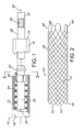
- System 16 for intraluminally delivering and deploying a radially self-expanding stent, stent-graft, or other prosthesis.
- System 16 includes an elongate and pliable outer catheter 18 constructed of a biocompatible material such as polypropylene, FEP, HDPE, PTFE, or PET.
- a central lumen 20 runs the length of catheter 18.
- the tubular wall of catheter 18 includes a distal wall segment 22 containing a radially self-expanding stent 24.
- stent 24 is of open weave or mesh construction formed of multiple helically wound and braided filaments or strands 26 of a flexible material such as body compatible stainless steel.
- Other suitable materials include shape memory alloys such as Nitinol, or biocompatible polymers.
- Stent 24 is shown in a free or relaxed state, i.e. the state assumed by the stent when subject to no external force.
- catheter 18 radially compresses stent 24, acting against an internal elastic restoring force of the stent to maintain the stent in an axially elongated, reduced-radius delivery state.
- An elongate and pliable inner member or catheter 28 extends along a length of the outer catheter, contained in lumen 20.
- a distal region 30 of inner catheter 28 is surrounded by the stent.
- Inner catheter 28 is movable axially relative to outer catheter 18.
- a proximal region 32 of the inner catheter extends proximally beyond a proximal end 34 of outer catheter 18, and is operable to control the axial position of distal region 30 relative to distal wall segment 22 of the outer catheter.
- Inner catheter 28 has an axially extending lumen 36 to accommodate a guidewire 38.
- An anchoring device 40 is fixed in surrounding relation to inner catheter 28, near a proximal end of distal region 32. As is later explained, device 40 is operable to anchor stent 24 with respect to inner catheter 28, enabling use of the inner catheter to retract and recover a partially deployed stent.
- a thrust member 42 is fixed in surrounding relation to inner catheter 28, proximally spaced apart from anchoring device 40.
- Inner catheter 28 is movable distally relative to outer catheter 18 to position thrust member 42 against the proximal end of stent 24, whereupon further distal travel of the inner catheter moves the stent distally relative to the outer catheter.
- Inner catheter 28 is movable proximally relative to outer catheter 18 to bring anchoring device 40 into a surface engagement with stent 24.
- the inner catheter is movable distally to bring thrust member 42 into to surface contact with the stent.
- the inner catheter acts as a control member, to selectively control the position of stent 24 relative to the outer catheter.
- stent 24 has a proximal end 44 at which strands 26 are formed into a plurality of elongate loops 46.
- the strands are formed into a plurality of bends 50.
- twenty-four helical windings twelve in each of two opposite directions, form twelve of the distal end bends 50, and six proximal end loops 46.
- Loops 46 are equally angularly spaced apart about the stent periphery or circumference, in increments of sixty degrees from each loop to each adjacent loop.
- the optimal numbers of strands, loops and bends can differ, depending on the strand material and the procedure involved.
- the oppositely directed strands form multiple intersections or crossing points 52.
- the stent is shown in its relaxed state, when subject to no external stress.
- Stent 24 is radially compressible, against an internal elastic restoring force, to an axially-elongated, reduced-radius delivery state.
- distal wall segment 22 of the outer catheter provides the external force necessary to maintain stent 24 in the reduced-radius state, thus to facilitate the intraluminal delivery of the stent to the intended treatment site.
- stent 24 exerts a radially outward force against distal wall segment 22 as a counter to the external force. This creates a frictional engagement of the stent and outer catheter, whereby the stent tends to follow proximal and distal movements of the outer catheter.
- Stent 24 is deployed through proximal movement of catheter 18 relative to inner catheter 28, with the inner catheter applying an axial (distal) force against the stent sufficient to overcome friction between the stent and outer catheter. This prevents the stent from moving proximally with the outer catheter. When free of outer catheter 18, stent 24 radially self-expands toward the relaxed state shown in Figure 2 .
- stent 24 closely surrounds but is not necessarily in contact with inner catheter 28.
- such contact not only is present, but must be maintained by exerting a radially inward force urging a stent against an inner catheter (or a sleeve or other gripping member along the inner catheter), to create a frictional hold that exceeds the frictional hold between the stent and the outer catheter.
- frictional systems provide for stent retraction, but at a cost: namely, a considerable increase in the axial force delivered by the inner catheter to deploy the stent.
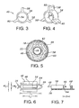
- anchoring device 40 is symmetrical about a longitudinal axis.
- a central opening 54 extends through the device, and has a diameter slightly larger than the outside diameter of inner catheter 28 at least along the distal region. This provides a slideable fit, to facilitate installation of the anchoring device onto the inner catheter, where the device can be fixed at its intended location by an adhesive, thermal processing, ultrasonic welding or other suitable approach.
- Anchoring device 40 includes a longitudinally extending sleeve 56.
- Three splines or fins 58 extend longitudinally along sleeve 56 and radially outward from the sleeve, to respective radially outward ends 60.
- Anchoring device 40 preferably is a unitary member, formed of a polymer such as ABS, polycarbonate, or nylon 12. Thus, it can be harder or more rigid than inner catheter 28 and outer catheter 18. As a result, the anchoring device when engaged with stent 24 through loops 46 can more positively anchor and otherwise control the position of the stent.
- each of fins 58 extends through one of loops 46, to a point beyond its associated loop and just inside of distal wall segment 22.
- an outer diameter defined by outward ends 60 is less than the inside diameter of the distal wall segment by an amount less than the radial thickness of loops 46, i.e. the diameter of strands 26.
- the radial spacing between each end 60 and the distal wall segment is less than one-half the strand diameter. This arrangement ensures a positive retention of each loop about its associated fin.
- each fin extends radially to position its outer end beyond a radial midpoint of its associated loop, i.e. beyond the geometric center of strand 26 as indicated by the broken line at 62.
- loops 46 are shown spaced apart inwardly from the distal wall segment. This is partly for convenience in illustrating the positional relationship between each fin and its associated loop. Further, at least a portion of each loop is spaced apart from the distal wall segment, by virtue of the fact that the profile of each loop as viewed in Figure 5 extends as a chord in relation to the circular profile of wall segment 22. Finally, this figure illustrates that there need not be a one-to-one correspondence of fins to loops, although it is preferable to have a symmetrical arrangement in which the number of loops is an integral multiple of the number of fins, as shown.
- FIGS 6 and 7 illustrate one of loops 46 surrounding its associated fin 58.
- fin 58 has a transverse width less than the corresponding interior width of loop 46.
- fin 58 can be tapered, with a width that increases in the radially inward direction, so that the loop tends to engage the opposite sides of the fin as it is placed onto the fin. In either event, fin 58 is positioned for limited axial travel within the associated loop.
- loop 46 follows the outer catheter and moves distally (to the left as viewed in Figures 6 and 7 ) until a proximal end surface 64 of the fin engages a proximal inside surface 66 of loop 46.
- the remaining two fins similarly engage proximal inside surfaces of their associated loops.
- device 40 functions as an anchor that prevents further distal movement of stent 24, despite further distal travel of the outer catheter.
- the proximal end surfaces of fins 58 extend radially, so that together they occupy a plane perpendicular to the axial direction. This promotes the anchoring function, particularly when the strand forming loop 46 has a circular profile or cross section.
- fin 58 and loop 46 it is preferred to couple fin 58 and loop 46 as shown, to allow limited relative axial travel.
- the fin and loop could be configured to form a close or tight coupling that would virtually prevent relative axial movement of the stent and inner catheter.
- the looser, more flexible coupling has several advantages.
- the loops and fins can be formed under less demanding tolerances. Further, with the more flexible coupling it is much easier for the physician to load stent 24 into outer catheter 18 while maintaining the stent position relative to inner catheter 28.
- loops 46 and fins 58 are elongate in the axial direction.
- the major dimension of the fin coincides with the direction of forces applied to the loop through the fin.
- fin 58 cooperates with the opposite axially extending sides of loop 46 to provide a more stable coupling of the loop and fin that not only limits relative axial travel, but also resists twisting of the stent relative to the inner catheter, even when allowing limited relative rotation to provide the advantages of less stringent tolerances and ease of stent loading.
- a distance D between end surface 64 of the fin and an end surface 68 of the thrust member is selected in conjunction with a diameter d of strand 26 forming the loop, to determine a range of axial travel of stent 24 relative to inner catheter 28.
- Distance D is from 1 mm to 2 mm and diameter d is 0.3 mm.
- the resulting range of axial travel is 0.7 mm to 1.7 mm, or in terms of the ratio D/d, is from 3.3 to 6.7.
- the ratio D/d is at least about 2.
- an axial length L 1 of the interior of loop 46 exceeds an axial length L 2 of fin 58 sufficiently to permit the required freedom of axial movement of the fin within the loop.
- L 1 can be 5.5 mm, with L 2 being 3-4 mm.
- an internal transverse width W 1 of loop 46 exceeds a transverse width W 2 of the fin. More specifically, W 1 can be 1.5 mm and W 2 can be 0.3 mm.
- W 1 is at least about twice W 2 .
- stent 24 surrounds the distal region of inner catheter 28, radially compressed in the reduced-radius delivery state by outer catheter 18.
- stent 24 is loaded into this position first by placing the stent in its relaxed state around the distal end region of the inner catheter, with loops 46 axially aligned with anchoring device 40. Then stent 24, at least along its proximal end near the loops, is elongated axially and radially reduced sufficiently to bring three of the loops about the three fins.
- the inner catheter and stent are moved proximally into the outer catheter, until the distal wall segment completely surrounds the stent, as shown in Figure 8 .
- system 16 is inserted into the body and moved distally along a vessel or other body lumen, until the distal ends of the catheters are positioned near the intended treatment site.
- the catheters are moved distally over a previously positioned guidewire, not shown.
- the user controls the proximal ends of the catheters, holding inner catheter 28 substantially stationary while proximally withdrawing outer catheter 18.
- Thrust member 42 engages stent 24 to prevent further proximal movement of the stent, in effect moving the stent distally relative to the outer catheter.
- the stent emerges from the distal end of the outer catheter, it radially self-expands toward its relaxed state, as seen in Figure 9 .
- the arrow indicates proximal movement of the outer catheter.
- outer catheter 18 is moved proximally a sufficient distance to nearly complete the deployment of stent 24. Over at least about half of its length, the stent has radially expanded into contact with surrounding tissue (not shown) at the treatment site.
- the arrow indicates that at this stage, outer catheter 18 may be moved in either axial direction, depending on the physician's determination of factors critical to the implantation procedure; e.g. whether the stent is properly positioned, and whether the stent has a diameter and axial length appropriate for the procedure.
- stent 24 may remain retractable with up to ninety-five percent of its length disposed distally of outer catheter 18.
- outer catheter 18 is moved further in the proximal direction, to completely release stent 24 for full radial expansion into contact with surrounding tissue, as indicated in Figure 11 . At this point, catheters 18 and 28 are withdrawn.
- outer catheter 18 is moved distally to recompress and recapture the stent, restoring the configuration shown in Figure 8 . Then, catheters 18 and 28 are moved in concert to reposition the stent, or are withdrawn to allow substitution of another stent.
- Anchoring device 40 unlike friction-based devices, adds nothing to the axial force needed to maintain inner catheter 28 and stent 24 in place while proximally withdrawing outer catheter 18. Likewise, this approach adds nothing to the axial force needed to retract a partially deployed stent.
- the coupling of stent 24 to inner catheter 28 through the anchoring device provides substantially the same anchoring force, regardless of the exigent of stent deployment. Unlike friction-based systems, the amount of axial holding force available to retract the stent does not diminish as deployment progresses. Thus, the physician can deploy stent 24 to a point of near completion as indicated in Figure 10 , confident that anchoring device 40 remains capable of retracting the stent if necessary. More accurate determinations relating to stent placement and size can be made with stent 24 at a stage close to full stage deployment as in Figure 10 . As compared to the partial deployment stage indicated in Figure 9 , or conventional designs that allow only partial deployment, the configuration in Figure 10 provides a better basis for making critical decisions regarding stent size and placement.
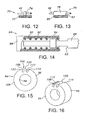
- Figure 12 illustrates part of an alternate embodiment anchoring device 70 including a sleeve 72 and a plurality of pins extended radially away from the sleeve, one of which is shown at 74.
- pin 74 extends through one of loops 46 or an opening in the stent lattice structure in the same manner as fin 58, while permitting a wider latitude of axial movement of the loop relative to the anchoring device. This approach may be more suitable to a prosthesis that has less columnar strength.
- Figure 13 showing a device not forming part of the invention shows a portion of another alternative anchoring device 76 in which several fins, one of which is shown at 78, extend radially away from a sleeve 80.
- a proximal end surface 82 of the fin is concave in the proximal direction. Consequently, when stent 24 is moved distally relative to the anchoring device, fins 78 function as hooks to more positively capture their associated loops.
- the capturing function can be achieved through other profiles in end surface 82, e.g. profiles with notches, slots, and other suitable depressions or concavities.
- end surface 82 can be inclined proximally as it extends radially outward to capture the associated loop.
- Figure 14 illustrates a distal portion of an embodiment prosthesis delivery and deployment system 84, including an outer catheter 86, an inner catheter 88 contained in a lumen 90 of the outer catheter for axial travel relative to the outer catheter, and a radially self-expanding stent 92 contained in a reduced-radius state along a distal wall segment of the outer catheter.
- a cylindrical anchoring device 94 is secured to the inner catheter, and is releasably engaged with a loop 102 at the proximal end of stent 92.
- catheter 88 is formed with a shoulder 93 to provide the thrust member or feature.
- anchoring device 94 includes a cylindrical body 96, with an opening 98 extending axially through the body to facilitate installation and mounting of the anchoring device along a distal end region of inner catheter 88.
- Anchoring device 94 is shaped to provide a control feature, specifically a medial feature 100, that interacts with a loop 102 of stent 92 in much the same manner as fin 58 interacts with loop 46.
- body 96 further is shaped to provide a recess 104 directed radially inwardly from an annular outside surface 106 of the body.
- Medial feature 100 extends radially outwardly from an inside central portion of the recess, in effect forming axially directed grooves or recess segments 108 and 110 between feature 100 and side features 112 and 114, respectively.
- Figures 17 and 18 illustrate loop 102 retained releasably within the recess.
- a strand 116 forming the loop includes spaced apart longitudinal sections 118 and 120, retained respectively in grooves 108 and 110.
- the outside diameter of body 96 is less than an inside diameter of catheter 86 along the distal wall segment, to enable the anchoring member to slide relative to the outer catheter.
- the difference between the body diameter and the inside diameter of the distal wall segment is less than the diameter of strand 116, to ensure that loop 102 is positively retained in recess 104, so long as the proximal portion of the prosthesis near loop 102 remains radially compressed.
- Figure 19 illustrates an alternative embodiment anchoring member 122, with recesses 124 and medial features 126 formed along opposite sides of a cylindrical body 128.
- Device 122 can be used with the single-loop stent shown in Figure 14 , or with a stent having two opposed proximal end loops.
- the number of recess/medial feature combinations can exceed the number of loops, but must at least equal the number of loops to accommodate all loops, due to the close spacing between body 128 and the outer catheter.
- medial feature 100 and loop 102 form a coupling that is asymmetrical, in the sense that the axial force does not act through a central axis of the anchoring device. Nonetheless, the narrow spacing between outside surface 106 and the inside surface of outer catheter 86 facilitates a smooth sliding movement of inner catheter 88 within the outer catheter.
- anchoring member 122 provides a symmetrical arrangement with a more balanced application of axial forces. In either arrangement, the number of recesses can be equal to, or an integral multiple of, the number of loops.
- anchoring devices 94 and 122 as compared to anchoring devices without recesses, is that they can more easily accommodate covered devices such as stent-grafts. This is because medial features 100 and 126 do not extend beyond the outer surfaces of their respective anchoring bodies, and thus do not interfere with a graft or other covering surrounding the stent.
- Figure 20 illustrates another alternative embodiment anchoring device 130 with a cylindrical anchoring body 132 and a recess 134 directed radially inwardly from an annular outside surface 136 of the body.
- a filament or strand 138 of a stent (not fully shown) is shaped into a loop or other linking member 140 at the proximal end of the stent.
- Recess 134 has a shape corresponding to the profile of loop 140, with a radially oriented recess wall that substantially surrounds the loop.
- the recess wall functions as the control feature, Consequently, so long as the stent is maintained in a reduced-radius state, anchoring device 130, through surface engagement with loop 140, can anchor the stent alternatively against proximal and distal movement relative to anchoring device 130 and its associated inner catheter.
- loop 140 provides a convenient proximal end linking member of a stent
- a bend, twist, or other enlargement formed in strand 138 can provide a suitable surface engagement with body 132 when captured within recess 134.
- strand 138 may include adjacent portions twisted together, yet terminating in a loop similar to loop 140. Looped ends are generally favored, due to their atraumatic character.
- the stent linking structure can consist of a single loop or other linking member, or a plurality of linking loops or members arranged angularly about the stent.
- stents and other prostheses of the radially self-expanding type are deployable at relatively low levels of axial force, and further are retrievable at multiple stages of deployment.
- Inner catheters or other inner members are provided with anchoring devices that have radially extending fins, recesses, or other features designed to interact with loops or other proximal-end linking members of prostheses, to anchor the prostheses through surface-to-surface engagement rather than friction, thus to provide more positive anchoring without the need for any additional axial force for prosthesis deployment or retraction.
Landscapes
- Health & Medical Sciences (AREA)
- Engineering & Computer Science (AREA)
- Biomedical Technology (AREA)
- Cardiology (AREA)
- Oral & Maxillofacial Surgery (AREA)
- Transplantation (AREA)
- Heart & Thoracic Surgery (AREA)
- Vascular Medicine (AREA)
- Life Sciences & Earth Sciences (AREA)
- Animal Behavior & Ethology (AREA)
- General Health & Medical Sciences (AREA)
- Public Health (AREA)
- Veterinary Medicine (AREA)
- Prostheses (AREA)
- Media Introduction/Drainage Providing Device (AREA)
Abstract
Description
- The present invention relates to systems for intraluminally delivering and deploying self-expanding stents and other prostheses, and more particularly to such systems that incorporate mechanisms for retrieving partially deployed prostheses.
- Stents, stent-grafts, and other body implantable tubular devices are employed in a wide variety of applications to maintain the patency of body lumens and guide the flow of blood and other body fluids through the lumens. These devices are employed in vascular applications, e.g. in pulmonary and thoracic vessels, and in arteries such as the coronary, renal, carotid, and iliac arteries. In addition to these vascular applications, the devices are used in the esophagus, duodenum, biliary duct, and colon. These devices may be either radially self-expanding or balloon-expandable in character. When deployed within body lumens, self-expanding devices radially expand into contact with surrounding tissue, typically assuming a diameter less than a fully expanded or relaxed state diameter. Consequently, an internal elastic restoring force acts outwardly against the tissue to assist in fixation of the device. Self-expanding devices frequently are preferred, due to this self-fixation capability.
- Most applications employing radially self-expanding devices require intraluminal delivery of the device in a configuration suitable for delivery, i.e. radially compressed to a reduced-radius state against its internal elastic restoring force. To this end, prosthesis delivery systems frequently include two catheters: an outer catheter releasably containing the radially compressed prosthesis in a lumen near its distal end, and an inner catheter contained in the lumen, positioned against or otherwise engaged with the prosthesis. The prosthesis is deployed by moving the outer catheter proximally while holding the inner catheter in place. This effectively moves the inner catheter and the prosthesis distally relative to the outer catheter, allowing the prosthesis to radially self-expand as it emerges from the distal end of the outer catheter.
- In either event, there arises on occasion a need to reverse the deployment. The need may arise from the physician's desire to reposition the prosthesis along the intended treatment site. Once a substantial portion of the prosthesis is free of the outer catheter, it may be moved in the proximal direction. However, at this point it is virtually impossible to move the prosthesis in the distal direction without retracting it proximally, back into the outer catheter. Accurate positioning of the prosthesis during deployment is challenging, in that it usually requires fluoroscopic imaging, and the difficulty is increased by the tendency of the many self-expanding devices to axially shorten as they radially self-expand. The need to retract a prosthesis can arise from other factors, e.g. a realization during deployment that a prosthesis of a different axial length or radius would be more effective at the designated treatment site.
- In many conventional deployment and delivery systems, retraction of a partially deployed prosthesis is virtually impossible. To provide a retractable prosthesis, an inner catheter or other member can be surrounded by a high friction sleeve or gripping member as shown in
U.S. Patent No. 5,026,377 (Burton et al. ), with the portion of an inner catheter supporting the sleeve and surrounded by the prosthesis. When the outer catheter radially compresses the prosthesis, it simultaneously presses the prosthesis into a frictional engagement with the sleeve. Accordingly, when the outer catheter is moved relative to the inner catheter, the prosthesis tends to remain with the inner catheter rather than following the outer catheter. A similar approach is shown inU.S. Patent No. 5, 817,102 (Johnson et al. ) in which an exterior catheter radially compresses a stent into contact with a restraining sleeve that surrounds an interior catheter. - While these arrangements permit proximal retraction of a partially deployed stent or other prosthesis, they rely on a frictional engagement of the prosthesis with the inner member, through the gripping member or restraining sleeve. The force due to the frictional engagement must be sufficient to overcome the tendency of the prosthesis to move with the outer catheter as the outer catheter moves relative to the inner member. This frictional force acts in the axial direction, but requires a force acting in the radial direction to urge the prosthesis against the gripping member. The required radial force adds to the radial force already exerted by the prosthesis against the outer catheter due to its internal elastic restoring force, thus to increase the axial pushing force required to overcome friction between the prosthesis and outer catheter, and deploy the prosthesis.
- Another factor inherent in this approach is the reduction in the frictional holding force as prosthesis deployment progresses, largely due to the diminishing portion of the prosthesis length subject to the frictional hold. As deployment progresses, the prosthesis becomes increasingly easy to deploy. Conversely, when the prosthesis is being pulled back into the catheter to reconstrain it; the reconstrainment force increases as more and more of the prosthesis is pulled into the catheter. This tendency can be counteracted by increasing the frictional holding force, but this in turn increases the radial force required to overcome the frictional hold, once again increasing the force required for ordinary deployment.
- Other arrangements involve axially tight or locking engagements of prostheses with inner member coupling structures. Examples of these arrangements are seen in
U.S. Patent No. 6,350,278 (Lenker et al. ) andU.S. Patent No. 5,733,325 (Robinson et al. ). These systems permit prosthesis retraction, but impose unduly stringent tolerances upon the coupling structure. Further, they require close attention and care on the part of the physician or other user when loading a prosthesis into the system, to ensure that the required coupling is achieved. -
US 6 520 983 B1 discloses a system for delivering a medical prosthesis into a body lumen. A preferred embodiment of the invention utilizes a catheter having a stent mounted at the distal end that is released into the body lumen by movement of an outer sheath covering the stent in the proximal direction. The stent expands to conform to the inner wall of the lumen and the catheter is withdrawn. -
US 2004/204749 A1 discloses a method and apparatus for reducing the longitudinal aspect of the catheter to stent force comprises at least one grip member for use with a stent delivery system. The grip engages a stent in the unexpanded state prior to delivery of the stent by retracting a stent retaining sheath. -
US 6 607 551 B1 discloses a stent delivery system deploys a stent having an inner periphery that defines an interior space extending lengthwise along at least a part of the stent and comprising at least one segment having relatively low column strength. The stent delivery system comprises a stabilizer which is disposed within the stent interior space and has a surface element adapted to engage the stent inner periphery in a region containing the low-column-strength segment. - Therefore, the present invention is disclosed in terms of several embodiments, each directed to at least one of the following objects:
- to provide a prosthesis deployment system with the capability of retracting partially deployed prostheses, without any substantial increase in the axial forces required to deploy the prostheses;
- to provide a prosthesis deployment system that permits retracting of the prosthesis at a later stage in its deployment, in terms of the fraction of the prosthesis axial length exposed, without degrading or losing retraction capability;
- to provide a deployment device that has greater stent retention capability if the need arises for withdrawing a partially deployed stent;
- to provide a deployment device capable of retracting partially deployed device in which an open-frame support structure is covered, e.g. as in stent-grafts; and
- to provide a prosthesis anchoring device suitable for attachment to an inner catheter or other inner member of a conventional prosthesis delivery and deployment system to provide the capability of retracting partially deployed prostheses.
- To achieve these and other objects, there is provided a device for effecting an intraluminal delivery and controlled deployment of a body implantable prosthesis. The invention is defined by the appended claims. The device includes an elongate prosthesis delivery member having a distal wall segment adapted to contain a radially self-expanding prosthesis in a reduced-radius delivery state against an internal restoring force. A radially self-expanding prosthesis is contained in the distal wall segment and thereby maintained in the reduced-radius delivery state. The prosthesis includes a linking structure near a proximal end of the prosthesis. An elongate prosthesis control member is mounted for axial travel relative to the delivery member, toward and away from a delivery position in which a distal end region of the control member extends along the distal wall segment of the delivery member and is disposed radially inwardly of the prosthesis. A control feature is disposed along the distal end region of the control member and extends radially outwardly from the control member beyond a radial midpoint of the linking structure when in the delivery position with the prosthesis so contained. Thus, the control feature is positioned to allow limited distal travel of the delivery member and prosthesis relative to the control member, and to effect a substantially non-frictional surface engagement with the linking structure upon said limited distal travel, to anchor the prosthesis against further distal travel relative to the control member.
- The delivery member can comprise an outer catheter with a lumen running substantially along its complete length. The control member can comprise an elongate inner catheter disposed in the outer catheter lumen. Preferably a proximal region of the inner catheter extends beyond a proximal end of the outer catheter, to facilitate the use of the inner catheter proximal end to control the position of the inner catheter distal region relative to the outer catheter. This facilitates control of the prosthesis deployment from outside the body.
- If desired, the control member can be provided with several control features, equally angularly spaced apart from each other about the control member, for use with a prosthesis in which the linking structure includes angularly spaced apart loops or other linking members. A one-to-one correspondence of control features and loops is workable, but not required. In one embodiment, three control features are used in conjunction with six loops formed at a proximal end of the prosthesis.
- In a preferred embodiment, a tubular sleeve supports a symmetrical arrangement of control features, and is sized to facilitate its slideable installation onto the distal end region of the control member. The sleeve and control features are formed as a unitary member, preferably more rigid than the control member to provide more positive control over the prosthesis through engagement of the control features with the loops or other linking members. The control features can be surrounded by substantially closed loops of a prosthesis linking structure, in which case the features can control both proximal and distal prosthesis movement.
- One aspect of the present invention is that the control feature outer ends define a control feature diameter less end than an inside diameter of the delivery member distal wall segment. At the same time, the radial spacing in between the control features and distal wall segment is less than half of a radial thickness dimension of the prosthesis linking structure. Consequently, the control member and control features are slideable relative to the delivery member with no frictional drag.
- Yet, the control feature outer ends are sufficiently close to the distal wall section to prevent the linking structure or another part of the prosthesis from wedging into the space between the control features and distal wall segment.
- A salient feature of the present invention is that the control member is operable to move the prosthesis proximally relative to the delivery device - or alternatively, to maintain the prosthesis substantially stationary while the delivery device is moved distally relative to the control member - through a surface engagement of each control feature with the prosthesis linking structure. The control features apply axial forces to the linking structure. Unlike the frictional prosthesis retraction systems discussed above, there is no need for frictional control of the prosthesis, and accordingly, no need for the additive radial force that undesirably increases the axial force required to deploy the prosthesis. Further, because the axial forces in the present system do not depend on friction, they do not diminish as prosthesis deployment progresses. As a result, the prosthesis can be fully retracted from a stage close to complete deployment, e.g. with up to ninety-five percent of its length positioned distally of the delivery device.
- Another aspect of the present invention is a prosthesis delivery and deployment device. The device includes an elongate prosthesis delivery member having a distal wall segment adapted to contain a radially self-expanding prosthesis in a reduced-radius delivery state against an internal restoring force. An elongate control member is mounted for axial travel relative to the delivery member, toward and away from a delivery position in which a distal end region of the control member extends along the distal wall segment of the delivery member. A prosthesis anchor is mounted to the distal end region and comprises at least one elongate axially directed control feature extending radially outwardly from the control member. The control feature thereby is positioned to effect a releasable engagement with a proximal-end linking structure of a radially self-expanding prosthesis when in the delivery position and with the prosthesis so contained. The anchor, when in said engagement with the linking structure, is operable to anchor the prosthesis against distal travel relative to the control member.
- Preferably, the anchor comprises a plurality of the elongate axially directed control features positioned to engage the linking structure. Then, the linking structure preferably includes a plurality of elongate axially directed loops, each associated with a different one of the control features. The anchor further can include a cylindrical anchoring body with a centrally located axial opening adapted to receive the control member and facilitate and mounting of the anchor in surrounding relation to the control member. The anchor advantageously can be more rigid than the control member, to provide a more positive engagement with its associated loop.
- The anchoring body has a recess directed inwardly from an outside surface of the anchoring body and adapted to receive a loop or other proximal-end linking structure of the prosthesis. The associated control feature is disposed in the recess, to be surrounded by the loop when the loop is received into the recess. The depth of the recess exceeds the radial thickness of the loop, so that the complete loop may be radially inwardly disposed relative to the outside surface.
- A further aspect of the present invention is a prosthesis anchoring device adapted for fixation to a prosthesis deployment member. The device includes a generally cylindrical anchoring sleeve having a central opening extending axially therethrough to facilitate a slideable installation of the anchoring sleeve onto an elongate prosthesis deployment member for fixation along a distal end region of the deployment member. A control feature extends radially outwardly from the anchoring sleeve and is adapted to extend radially into a proximal-end linking structure of a radially self-expanding prosthesis when the prosthesis is maintained in a reduced-radius state against an internal restoring force and selectively axially aligned with the distal end region. The control feature, with the anchoring sleeve fixed to a deployment member and when so extending into a proximal-end linking structure of a radially self-expanding prosthesis so maintained and aligned, is adapted to engage the linking structure to prevent any substantial distal movement of the prosthesis relative to the deployment member.
- Preferably, the control feature is elongate, directed axially, and adapted to extend into a prosthesis proximal-end linking structure taking the form of an elongate, axially extended loop. When surrounded by the loop, the control feature prevents any substantial distal movement of the loop relative to the anchoring body. In a more preferred version of the device, a plurality of the elongate control features are angularly spaced apart from one another about the anchoring body.
- The anchoring body includes a recess receding radially inwardly from its outside surface to receive the linking structure. The control feature is disposed within the recess. Typically, the depth of the recess exceeds the thickness of the linking structure. In systems that employ an outer catheter or other delivery device with a distal wall section designed to maintain a radially self-expandable prosthesis in a reduced-radius delivery state, the anchoring body can be dimensioned for a close fit within the distal wall section. As a result, the distal wall segment cooperates with the walls of the recess to capture the linking structure within the recess, while permitting the anchoring body to slide axially along the distal wall section.
- To provide a more secure retention of the linking structure, the recess is formed with a size and shape corresponding to that of the linking structure. For example, if the linking structure comprises an elongate linking strand formed into a loop, the recess can have a perimeter that closely corresponds to a perimeter of the loop. The control feature disposed in the recess is surrounded by the loop when the loop is retained in the recess. When surrounded by the loop, the control feature prevents any substantial distal movement of the loop relative to the anchoring body. As a result, the deployment member is operable through the anchoring body to deploy and retract the prosthesis.
- In short, an anchoring body formed according to the present invention, with a central aperture sized according to a conventional prosthesis deployment catheter and with one or more control features sized according to the corresponding loops or other linking structure of a selected prosthesis, can considerably improve the prosthesis retraction capability of a prosthesis delivery and deployment system, without increasing the axial force required for deployment.
- Several additional features enhance deployment system performance, regardless of whether the control features are recessed. For example, when the anchoring device is provided as a unitary structure including a cylindrical anchoring body and outwardly protruding control features, the device may be attached to a conventional inner catheter or other control member, fixed to the inner catheter at a location selected in accordance with the compressed length of the prosthesis to be deployed. Further, a relatively hard anchoring device can be fixed to a softer, more compliant inner catheter or control member, providing the capacity to negotiate serpentine internal passageways, while at the same time providing more positive control over the prosthesis through the relatively rigid control features.
- Another useful feature arises from the provision of elongate control features and their axial orientation along the control member. This aligns the major dimension of each control feature with the direction of the forces applied through the control feature to the prosthesis, to overcome its tendency to follow the outer catheter or other prosthesis delivery member. As a result, the control features are more stable and less prone to unwanted flexure. The elongate axially directed features, as compared to pins or other features with circular cross sections, are better suited to limit twisting of the prosthesis relative to the control member. At the same time, the control features can have transverse widths selected to allow limited prosthesis rotation.
- Yet another advantage arises from the positioning of each control feature to allow limited distal travel of the delivery member and prosthesis before the prosthesis engages the linking structure, and then to effect non-frictional surface engagement with the linking structure responsive to the limited distal travel. As compared to previous deployment systems with interlocks designed to prevent any axial movement of a prosthesis relative to an inner catheter or other control member, the novel coupling of the control feature and linking structure can be manufactured under tolerances that are less stringent. Further, loading the prosthesis into an outer catheter or other delivery member, while maintaining a prosthesis radially compressed and coupled to the control member through the control features, is much easier.
- Yet another aspect of the present invention is a process for loading a radially self-expanding prosthesis for subsequent deployment in a body lumen, comprising the following steps:
- a. positioning a radially self-expanding prosthesis along and in surrounding relation to a distal end region of an elongate prosthesis control member with a proximal end linking structure of the prosthesis disposed near axially spaced apart first and second features that extend radially outwardly from the control member;
- b. with the prosthesis so positioned, radially contracting the prosthesis to a reduced-radius delivery state against an internal elastic restoring force, to move the linking structure into a delivery position between the first and second features, whereby the first and second features cooperate to limit axial travel of the prosthesis relative to the control member to a predetermined range so long as the prosthesis remains in the delivery state; and
- c. selecting an axial dimension of the linking structure with respect to an axial spacing between the first and second features whereby the predetermined range is at least twice the axial dimension of the linking structure.
- Thus in accordance with the present invention, systems for intraluminally deploying radially self-expanding stents, stent-grafts and other implantable devices may be used to retract and withdraw such devices, even when deployment is near completion. There is no need for frictional retention of the device, and no resulting increase in axial force required for deployment. With the devices nearly deployed, yet retractable, physicians can evaluate prosthesis length, radius, placement relative to the treatment site, and other factors with more certainty as a basis for making critical decisions.
- For a further understanding of the above and other features and advantages, reference is made to the following detailed description and to the drawings, in which:
-
Figure 1 is a partial side elevation of a stent delivery and deployment system; -
Figure 2 is a side elevation of a radially self-expanding stent deployable with the system ofFigure 1 ; -
Figure 3 is a forward elevation of a stent anchoring device employed in the system ofFigure 1 ; -
Figure 4 is a perspective view of the anchoring device; -
Figure 5 is a sectional view taken along the line 5-5 inFigure 1 ; -
Figure 6 is a schematic top view of a control feature of the anchoring device, surrounded by a loop of the stent; -
Figure 7 is a schematic side view, partially in section, of the control feature and loop; -
Figures 8-11 schematically illustrate use of the system to deploy the stent; -
Figure 12 is a schematic view similar to that inFigure 7 , showing an alternative anchoring device; -
Figure 13 is a schematic view illustrating another alternative anchoring device; -
Figure 14 is a partial side elevation of an alternative embodiment stent delivery and deployment system constructed according to the present invention; -
Figure 15 is a forward elevation of a stent anchoring device employed in the system ofFigure 14 ; -
Figure 16 is a perspective view of the anchoring device; -
Figure 17 is a top view illustrating a loop of a radially self-expanding stent disposed in a recess of the anchoring device; -
Figure 18 is a forward elevation, partly in section, of the loop in the recess; -
Figure 19 is a forward elevation of an alternative embodiment stent anchoring device; and -
Figure 20 is a top view illustrating another alternative anchoring device and stent linking member. - Turning now to the drawings, there is shown in
Figure 1 asystem 16 for intraluminally delivering and deploying a radially self-expanding stent, stent-graft, or other prosthesis.System 16 includes an elongate and pliableouter catheter 18 constructed of a biocompatible material such as polypropylene, FEP, HDPE, PTFE, or PET. Acentral lumen 20 runs the length ofcatheter 18. The tubular wall ofcatheter 18 includes adistal wall segment 22 containing a radially self-expandingstent 24. With reference toFigure 2 ,stent 24 is of open weave or mesh construction formed of multiple helically wound and braided filaments orstrands 26 of a flexible material such as body compatible stainless steel. Other suitable materials include shape memory alloys such as Nitinol, or biocompatible polymers. -
Stent 24 is shown in a free or relaxed state, i.e. the state assumed by the stent when subject to no external force. Returning toFigure 1 ,catheter 18 radially compressesstent 24, acting against an internal elastic restoring force of the stent to maintain the stent in an axially elongated, reduced-radius delivery state. - An elongate and pliable inner member or
catheter 28 extends along a length of the outer catheter, contained inlumen 20. Whensystem 16 is configured for stent delivery as shown inFigure 1 , adistal region 30 ofinner catheter 28 is surrounded by the stent.Inner catheter 28 is movable axially relative toouter catheter 18. Aproximal region 32 of the inner catheter extends proximally beyond aproximal end 34 ofouter catheter 18, and is operable to control the axial position ofdistal region 30 relative todistal wall segment 22 of the outer catheter.Inner catheter 28 has an axially extendinglumen 36 to accommodate aguidewire 38. - An
anchoring device 40 is fixed in surrounding relation toinner catheter 28, near a proximal end ofdistal region 32. As is later explained,device 40 is operable to anchorstent 24 with respect toinner catheter 28, enabling use of the inner catheter to retract and recover a partially deployed stent. - A
thrust member 42 is fixed in surrounding relation toinner catheter 28, proximally spaced apart from anchoringdevice 40.Inner catheter 28 is movable distally relative toouter catheter 18 to position thrustmember 42 against the proximal end ofstent 24, whereupon further distal travel of the inner catheter moves the stent distally relative to the outer catheter. -
Inner catheter 28 is movable proximally relative toouter catheter 18 to bring anchoringdevice 40 into a surface engagement withstent 24. Alternatively, the inner catheter is movable distally to bringthrust member 42 into to surface contact with the stent. Thus, the inner catheter acts as a control member, to selectively control the position ofstent 24 relative to the outer catheter. - As seen in
Figure 2 ,stent 24 has aproximal end 44 at whichstrands 26 are formed into a plurality ofelongate loops 46. At adistal end 48 of the stent, the strands are formed into a plurality ofbends 50. In this version, twenty-four helical windings, twelve in each of two opposite directions, form twelve of the distal end bends 50, and sixproximal end loops 46.Loops 46 are equally angularly spaced apart about the stent periphery or circumference, in increments of sixty degrees from each loop to each adjacent loop. The optimal numbers of strands, loops and bends can differ, depending on the strand material and the procedure involved. The oppositely directed strands form multiple intersections or crossing points 52. The stent is shown in its relaxed state, when subject to no external stress. -
Stent 24 is radially compressible, against an internal elastic restoring force, to an axially-elongated, reduced-radius delivery state. As seen inFigure 1 ,distal wall segment 22 of the outer catheter provides the external force necessary to maintainstent 24 in the reduced-radius state, thus to facilitate the intraluminal delivery of the stent to the intended treatment site. When contained in this fashion,stent 24 exerts a radially outward force againstdistal wall segment 22 as a counter to the external force. This creates a frictional engagement of the stent and outer catheter, whereby the stent tends to follow proximal and distal movements of the outer catheter.Stent 24 is deployed through proximal movement ofcatheter 18 relative toinner catheter 28, with the inner catheter applying an axial (distal) force against the stent sufficient to overcome friction between the stent and outer catheter. This prevents the stent from moving proximally with the outer catheter. When free ofouter catheter 18,stent 24 radially self-expands toward the relaxed state shown inFigure 2 . - In
system 16,stent 24 closely surrounds but is not necessarily in contact withinner catheter 28. In contrast, in deployment systems that provide retraction through a frictional hold on the stent or other prosthesis, such contact not only is present, but must be maintained by exerting a radially inward force urging a stent against an inner catheter (or a sleeve or other gripping member along the inner catheter), to create a frictional hold that exceeds the frictional hold between the stent and the outer catheter. Thus, frictional systems provide for stent retraction, but at a cost: namely, a considerable increase in the axial force delivered by the inner catheter to deploy the stent. This is because the axial force must overcome not only the friction from the aforementioned restoring force of the stent, but the additional friction due to the additional radial force needed to press the stent against the inner catheter or gripping member.System 16, by providing an essentially non-frictional engagement ofstent 24 withinner catheter 28, provides for stent retraction without increasing the axial force needed to deploy the stent. - As seen in
Figure 1 , whenstent 24 is radially compressed in the delivery state, it is releasably coupled toinner catheter 28 through anchoringdevice 40. With reference toFigure 3 anchoring device 40 is symmetrical about a longitudinal axis. Acentral opening 54 extends through the device, and has a diameter slightly larger than the outside diameter ofinner catheter 28 at least along the distal region. This provides a slideable fit, to facilitate installation of the anchoring device onto the inner catheter, where the device can be fixed at its intended location by an adhesive, thermal processing, ultrasonic welding or other suitable approach. Anchoringdevice 40 includes alongitudinally extending sleeve 56. Three splines orfins 58 extend longitudinally alongsleeve 56 and radially outward from the sleeve, to respective radially outward ends 60. - Anchoring
device 40 preferably is a unitary member, formed of a polymer such as ABS, polycarbonate, or nylon 12. Thus, it can be harder or more rigid thaninner catheter 28 andouter catheter 18. As a result, the anchoring device when engaged withstent 24 throughloops 46 can more positively anchor and otherwise control the position of the stent. - The nature of the coupling between anchoring
device 40 andstent 24 is best understood with reference toFigures 5-7 . Showing a device not part of the invention. As best seen inFigure 5 , each offins 58 extends through one ofloops 46, to a point beyond its associated loop and just inside ofdistal wall segment 22. Preferably, an outer diameter defined by outward ends 60 is less than the inside diameter of the distal wall segment by an amount less than the radial thickness ofloops 46, i.e. the diameter ofstrands 26. The result is that in a coaxial arrangement, the radial spacing between each end 60 and the distal wall segment is less than one-half the strand diameter. This arrangement ensures a positive retention of each loop about its associated fin. - In a satisfactory but less preferred arrangement, each fin extends radially to position its outer end beyond a radial midpoint of its associated loop, i.e. beyond the geometric center of
strand 26 as indicated by the broken line at 62. - In
Figure 5 ,loops 46 are shown spaced apart inwardly from the distal wall segment. This is partly for convenience in illustrating the positional relationship between each fin and its associated loop. Further, at least a portion of each loop is spaced apart from the distal wall segment, by virtue of the fact that the profile of each loop as viewed inFigure 5 extends as a chord in relation to the circular profile ofwall segment 22. Finally, this figure illustrates that there need not be a one-to-one correspondence of fins to loops, although it is preferable to have a symmetrical arrangement in which the number of loops is an integral multiple of the number of fins, as shown. -
Figures 6 and 7 illustrate one ofloops 46 surrounding its associatedfin 58. As shown inFigure 6 ,fin 58 has a transverse width less than the corresponding interior width ofloop 46. Alternatively,fin 58 can be tapered, with a width that increases in the radially inward direction, so that the loop tends to engage the opposite sides of the fin as it is placed onto the fin. In either event,fin 58 is positioned for limited axial travel within the associated loop. Whenouter catheter 18 is moved distally relative toinner catheter 28,loop 46 follows the outer catheter and moves distally (to the left as viewed inFigures 6 and 7 ) until aproximal end surface 64 of the fin engages a proximalinside surface 66 ofloop 46. The remaining two fins similarly engage proximal inside surfaces of their associated loops. Once the loops and fins are engaged,device 40 functions as an anchor that prevents further distal movement ofstent 24, despite further distal travel of the outer catheter. The proximal end surfaces offins 58 extend radially, so that together they occupy a plane perpendicular to the axial direction. This promotes the anchoring function, particularly when thestrand forming loop 46 has a circular profile or cross section. - It is preferred to couple
fin 58 andloop 46 as shown, to allow limited relative axial travel. As an alternative, the fin and loop could be configured to form a close or tight coupling that would virtually prevent relative axial movement of the stent and inner catheter. The looser, more flexible coupling has several advantages. The loops and fins can be formed under less demanding tolerances. Further, with the more flexible coupling it is much easier for the physician to loadstent 24 intoouter catheter 18 while maintaining the stent position relative toinner catheter 28. - As perhaps best seen in
Figure 6 ,loops 46 andfins 58 are elongate in the axial direction. Thus, the major dimension of the fin coincides with the direction of forces applied to the loop through the fin. Further,fin 58 cooperates with the opposite axially extending sides ofloop 46 to provide a more stable coupling of the loop and fin that not only limits relative axial travel, but also resists twisting of the stent relative to the inner catheter, even when allowing limited relative rotation to provide the advantages of less stringent tolerances and ease of stent loading. - Preferably a distance D between
end surface 64 of the fin and anend surface 68 of the thrust member is selected in conjunction with a diameter d ofstrand 26 forming the loop, to determine a range of axial travel ofstent 24 relative toinner catheter 28. Distance D is from 1 mm to 2 mm and diameter d is 0.3 mm. The resulting range of axial travel is 0.7 mm to 1.7 mm, or in terms of the ratio D/d, is from 3.3 to 6.7. Advantageously, the ratio D/d is at least about 2. - Further, an axial length L1 of the interior of
loop 46 exceeds an axial length L2 offin 58 sufficiently to permit the required freedom of axial movement of the fin within the loop. For example, L1 can be 5.5 mm, with L2 being 3-4 mm. To allow limited rotation or transverse movement of the prosthesis relative to the inner catheter, an internal transverse width W1 ofloop 46 exceeds a transverse width W2 of the fin. More specifically, W1 can be 1.5 mm and W2 can be 0.3 mm. Advantageously, W1 is at least about twice W2. - The use of anchoring
device 40 to control stent deployment is illustrated inFigures 8-11 . InFigure 8 ,stent 24 surrounds the distal region ofinner catheter 28, radially compressed in the reduced-radius delivery state byouter catheter 18. Typically,stent 24 is loaded into this position first by placing the stent in its relaxed state around the distal end region of the inner catheter, withloops 46 axially aligned with anchoringdevice 40. Thenstent 24, at least along its proximal end near the loops, is elongated axially and radially reduced sufficiently to bring three of the loops about the three fins. The inner catheter and stent are moved proximally into the outer catheter, until the distal wall segment completely surrounds the stent, as shown inFigure 8 . At this point,system 16 is inserted into the body and moved distally along a vessel or other body lumen, until the distal ends of the catheters are positioned near the intended treatment site. The catheters are moved distally over a previously positioned guidewire, not shown. - At this stage, the user controls the proximal ends of the catheters, holding
inner catheter 28 substantially stationary while proximally withdrawingouter catheter 18.Thrust member 42 engagesstent 24 to prevent further proximal movement of the stent, in effect moving the stent distally relative to the outer catheter. As the stent emerges from the distal end of the outer catheter, it radially self-expands toward its relaxed state, as seen inFigure 9 . The arrow indicates proximal movement of the outer catheter. - As depicted in
Figure 10 ,outer catheter 18 is moved proximally a sufficient distance to nearly complete the deployment ofstent 24. Over at least about half of its length, the stent has radially expanded into contact with surrounding tissue (not shown) at the treatment site. The arrow indicates that at this stage,outer catheter 18 may be moved in either axial direction, depending on the physician's determination of factors critical to the implantation procedure; e.g. whether the stent is properly positioned, and whether the stent has a diameter and axial length appropriate for the procedure. In practice,stent 24 may remain retractable with up to ninety-five percent of its length disposed distally ofouter catheter 18. - If the stent is properly positioned, and the earlier determinations as to stent size are confirmed,
outer catheter 18 is moved further in the proximal direction, to completely releasestent 24 for full radial expansion into contact with surrounding tissue, as indicated inFigure 11 . At this point,catheters - Conversely, if
stent 24 needs to be repositioned or replaced,outer catheter 18 is moved distally to recompress and recapture the stent, restoring the configuration shown inFigure 8 . Then,catheters - Several advantages of
system 16, as compared to retraction devices that rely on friction, can be appreciated in conjunction withFigures 8-11 . The first of these is lower axial deployment force. Anchoringdevice 40, unlike friction-based devices, adds nothing to the axial force needed to maintaininner catheter 28 andstent 24 in place while proximally withdrawingouter catheter 18. Likewise, this approach adds nothing to the axial force needed to retract a partially deployed stent. - Moreover, the coupling of
stent 24 toinner catheter 28 through the anchoring device provides substantially the same anchoring force, regardless of the exigent of stent deployment. Unlike friction-based systems, the amount of axial holding force available to retract the stent does not diminish as deployment progresses. Thus, the physician can deploystent 24 to a point of near completion as indicated inFigure 10 , confident that anchoringdevice 40 remains capable of retracting the stent if necessary. More accurate determinations relating to stent placement and size can be made withstent 24 at a stage close to full stage deployment as inFigure 10 . As compared to the partial deployment stage indicated inFigure 9 , or conventional designs that allow only partial deployment, the configuration inFigure 10 provides a better basis for making critical decisions regarding stent size and placement. -
Figure 12 illustrates part of an alternate embodiment anchoring device 70 including asleeve 72 and a plurality of pins extended radially away from the sleeve, one of which is shown at 74. Whenstent 24 is constrained to the reduced-radius state,pin 74 extends through one ofloops 46 or an opening in the stent lattice structure in the same manner asfin 58, while permitting a wider latitude of axial movement of the loop relative to the anchoring device. This approach may be more suitable to a prosthesis that has less columnar strength. -
Figure 13 showing a device not forming part of the invention shows a portion of anotheralternative anchoring device 76 in which several fins, one of which is shown at 78, extend radially away from asleeve 80. Aproximal end surface 82 of the fin is concave in the proximal direction. Consequently, whenstent 24 is moved distally relative to the anchoring device,fins 78 function as hooks to more positively capture their associated loops. The capturing function can be achieved through other profiles inend surface 82, e.g. profiles with notches, slots, and other suitable depressions or concavities. As a further alternative,end surface 82 can be inclined proximally as it extends radially outward to capture the associated loop. -
Figure 14 illustrates a distal portion of an embodiment prosthesis delivery anddeployment system 84, including anouter catheter 86, aninner catheter 88 contained in alumen 90 of the outer catheter for axial travel relative to the outer catheter, and a radially self-expandingstent 92 contained in a reduced-radius state along a distal wall segment of the outer catheter. Acylindrical anchoring device 94 is secured to the inner catheter, and is releasably engaged with aloop 102 at the proximal end ofstent 92. In lieu of a thrust member (e.g. 42),catheter 88 is formed with ashoulder 93 to provide the thrust member or feature. - As seen in
Figures 15 and 16 , anchoringdevice 94 includes acylindrical body 96, with anopening 98 extending axially through the body to facilitate installation and mounting of the anchoring device along a distal end region ofinner catheter 88. Anchoringdevice 94 is shaped to provide a control feature, specifically amedial feature 100, that interacts with aloop 102 ofstent 92 in much the same manner asfin 58 interacts withloop 46. However,body 96 further is shaped to provide arecess 104 directed radially inwardly from an annularoutside surface 106 of the body.Medial feature 100 extends radially outwardly from an inside central portion of the recess, in effect forming axially directed grooves orrecess segments feature 100 and side features 112 and 114, respectively. -
Figures 17 and 18 illustrateloop 102 retained releasably within the recess. Astrand 116 forming the loop includes spaced apartlongitudinal sections grooves body 96 is less than an inside diameter ofcatheter 86 along the distal wall segment, to enable the anchoring member to slide relative to the outer catheter. Also, the difference between the body diameter and the inside diameter of the distal wall segment is less than the diameter ofstrand 116, to ensure thatloop 102 is positively retained inrecess 104, so long as the proximal portion of the prosthesis nearloop 102 remains radially compressed. -
Figure 19 illustrates an alternativeembodiment anchoring member 122, withrecesses 124 andmedial features 126 formed along opposite sides of acylindrical body 128.Device 122 can be used with the single-loop stent shown inFigure 14 , or with a stent having two opposed proximal end loops. Thus, the number of recess/medial feature combinations can exceed the number of loops, but must at least equal the number of loops to accommodate all loops, due to the close spacing betweenbody 128 and the outer catheter. - In anchoring
device 94,medial feature 100 andloop 102 form a coupling that is asymmetrical, in the sense that the axial force does not act through a central axis of the anchoring device. Nonetheless, the narrow spacing betweenoutside surface 106 and the inside surface ofouter catheter 86 facilitates a smooth sliding movement ofinner catheter 88 within the outer catheter. In contrast, anchoringmember 122 provides a symmetrical arrangement with a more balanced application of axial forces. In either arrangement, the number of recesses can be equal to, or an integral multiple of, the number of loops. - An advantage of anchoring
devices -
Figure 20 illustrates another alternativeembodiment anchoring device 130 with acylindrical anchoring body 132 and arecess 134 directed radially inwardly from an annularoutside surface 136 of the body. A filament or strand 138 of a stent (not fully shown) is shaped into a loop or other linkingmember 140 at the proximal end of the stent.Recess 134 has a shape corresponding to the profile ofloop 140, with a radially oriented recess wall that substantially surrounds the loop. The recess wall functions as the control feature, Consequently, so long as the stent is maintained in a reduced-radius state, anchoringdevice 130, through surface engagement withloop 140, can anchor the stent alternatively against proximal and distal movement relative to anchoringdevice 130 and its associated inner catheter. - While
loop 140 provides a convenient proximal end linking member of a stent, it is apparent fromFigure 20 that a bend, twist, or other enlargement formed instrand 138 can provide a suitable surface engagement withbody 132 when captured withinrecess 134. Further,strand 138 may include adjacent portions twisted together, yet terminating in a loop similar toloop 140. Looped ends are generally favored, due to their atraumatic character. As with previous embodiments, the stent linking structure can consist of a single loop or other linking member, or a plurality of linking loops or members arranged angularly about the stent. - Thus in accordance with the present invention, stents and other prostheses of the radially self-expanding type are deployable at relatively low levels of axial force, and further are retrievable at multiple stages of deployment. Inner catheters or other inner members are provided with anchoring devices that have radially extending fins, recesses, or other features designed to interact with loops or other proximal-end linking members of prostheses, to anchor the prostheses through surface-to-surface engagement rather than friction, thus to provide more positive anchoring without the need for any additional axial force for prosthesis deployment or retraction.
Claims (15)
- A system (16, 84) for effecting an intraluminal delivery and controlled deployment of a body implantable prosthesis (24, 92) comprising:an elongate prosthesis delivery member (18, 86) having a distal wall segment (22) adapted to contain a radially self-expanding prosthesis (24, 92) in a delivery position and in a reduced-radius delivery state against an internal restoring force;a generally cylindrical anchoring sleeve (40, 94, 122) having a central opening (54, 98) extending axially therethrough to facilitate a slideable installation of the anchoring sleeve (40, 94) onto an elongate prosthesis deployment member (28, 88) for fixation along a distal end region (30) of the deployment member (28, 88);a radially self-expanding prosthesis (24, 92) contained in the distal wall segment (22) and thereby maintained in the reduced-radius delivery state, said prosthesis (24, 92) including a plurality of helically wound strands (26) interbraided to define an open tubular frame structure having a proximal end (44) anda distal end (48), wherein the strands (26) at the proximal end (44) are formed into a plurality of axially elongated loops (46, 102) within the frame structure of the prosthesis to define a linking structure (46, 102) at the proximal end (44) of the prosthesis (24, 92) thereat, each of the plurality of axially elongated loops (46, 102) having spaced apart longitudinal sections (118, 120);characterized in thata control feature disposed on the anchoring sleeve (40, 94, 122) and extending radially outwardly into a the radially self-expanding prosthesis (24, 92) at a the proximal-end linking structure (46, 102) of the radially self-expanding prosthesis (24, 92) when the prosthesis (24, 92) is maintained in a reduced-radius state against an internal restoring force and selectively axially aligned with said distal end region; andwherein the anchoring sleeve (94, 122) comprises a cylindrical body (96, 128) having an annular outside surface, said annular outside surface (106, 136) having a plurality of recesses (104, 124, 134) directed radially inward from the annular outside surface (106, 136) to form axially directed recess segments (108, 110) having recess walls to define said control feature, wherein the axially directed recess segments (108, 110) retain each axially elongated loop (46, 102) of the prosthesis (24, 92) such that medial portions (100, 126) of the cylindrical body (96, 128) between the pairs of axially directed recess segments (108, 110) extend into the elongate loops (46, 102), thereby forming the control feature having a size and shape corresponding to that of the axially elongated loops (46, 102);whereby the control feature, when so extending into a proximal-end linking structure (46, 102) of the radially self-expanding prosthesis (24, 92) so maintained and aligned, is adapted to engage the linking structure (46, 102) to prevent any substantial distal movement of the prosthesis (24, 92) relative to the deployment member (28, 88).
- The system (16, 84) of claim 1 further including:a thrust feature (42, 93) disposed along the deployment member (28, 88), spaced apart proximally from the control feature, and positioned to allow limited proximal travel of the delivery member (18, 86) and prosthesis (24, 92) relative to the deployment member (28, 88) when in the delivery position with the prosthesis (24, 92) so contained, and to engage the proximal end (44) of the prosthesis (24, 92) responsive to said limited proximal travel and thereby prevent further proximal travel of the prosthesis (24, 92) relative to the deployment member (28, 88).
- The system (16, 84) of claim 1 wherein:the distal end region (30) is surrounded by the prosthesis (24, 92) when in said delivery position.
- The system (16, 84) of claim 1 wherein:the delivery member (18, 86) comprises an elongate outer catheter (18, 86) having a lumen (20) running substantially the entire length of the outer catheter (18, 86).
- The system (16, 84) of claim 4 wherein:the deployment member (28, 88) comprises an elongate inner catheter (28, 88) disposed in said lumen (20), wherein a proximal region (32) of the inner catheter (28, 88) extends proximally beyond a proximal end (34) of the outer catheter (18, 86) to facilitate use of the proximal region (32) to control a position of the distal region (30) relative to the outer catheter (18, 86).
- The system (16, 84) of claim 1 wherein:the anchoring sleeve (94, 122) and the control feature are formed as a unitary member.
- The system (16, 84) of claim 2 wherein:the linking structure (46, 102) has an axial dimension (L1) along a portion of the prosthesis (24, 92) disposed between the thrust feature (42, 93) and the control feature when the prosthesis (24, 92) is so contained, and an axial spacing (D) between the thrust feature (42, 93) and the control feature is selected to determine a range, for axial travel of the prosthesis (24, 92) relative to the control member, of 3.3 to 6.7 times said axial dimension (L1).
- The system (16, 84) of claim 7 wherein:said range for axial travel is at least about 0.7 mm and at most about 1.7 mm.
- The system (16, 84) of claim 1 wherein:a radial self-expansion of the prosthesis (24, 92) upon its release from the delivery member (18, 86) carries the linking structure (46, 102) radially outward beyond the control feature, thus to disengage the prosthesis from the deployment member (28, 88).
- The system (16, 84) of claim 1 wherein:said recesses (108, 110) are directed inwardly a distance greater than said radial thickness dimension of the loops.
- The system (16, 84) of claim 1 wherein:the distal end region (30) is surrounded by the prosthesis (24, 92) when in said delivery position.
- The system (16, 84) of claim 1 wherein:the cylindrical body (96, 128) comprises a centrally located axial opening (54) therethrough adapted to receive the deployment member (28, 88) and facilitate a mounting of the anchoring sleeve (94, 122) in surrounding relation to the deployment member (28, 88).
- The system (16, 84) of claim 1 wherein:the anchoring sleeve (94, 122) and the control feature are formed as a unitary member.
- A process for loading a radially self-expanding prosthesis (24, 92) for subsequent deployment in a body lumen, including:providing a radially self-expanding prosthesis (24, 92) comprising a plurality of helically wound strands (26) interbraided to define an open tubular frame structure having a proximal end (44) and a distal end (48), wherein the strands (26) at the proximal end (44) are formed into a plurality of axially elongated loops (46, 102) having spaced apart longitudinal sections (118, 120) to define the proximal-end linking structure (46, 102) of the radially self-expanding prosthesis (24, 92) thereat;positioning the radially self-expanding prosthesis (24, 92) along and in surrounding relation to a distal end region (30) of an elongate prosthesis control member (28, 88), wherein the control member (28, 88) comprises a cylindrical body (96, 128) having an annular outside surface, said annular outside surface having a plurality of recesses (104, 124) directed radially inward from the annular outside surface to form axially directed recess segments (108, 110) having recess walls (112, 114), wherein the axially directed recess segments (108, 110) retain each of the spaced apart longitudinal sections (118, 120) of the axially elongated loops (46, 102) of the prosthesis (24, 92) such that medial portions (100, 126) of the cylindrical body (96, 128) between the pairs of axially directed recess segments (108, 110) extend into the elongate loops (46, 102), thereby forming a control feature having a size and shape corresponding to that of the axially elongated loops (46, 102); andwith the prosthesis (24, 92) so positioned, radially contracting the prosthesis (24, 92) to a reduced-radius delivery state against an internal elastic restoring force to move the linking structure (46, 102) into a delivery position.
- The process of claim 14 wherein:radially contracting the prosthesis (24, 92) comprises progressively advancing a prosthesis delivery member (18, 86) over the prosthesis (24, 92) to contain the prosthesis (24, 92) in the delivery state within a lumen (20) of the delivery member (18, 86).
Applications Claiming Priority (2)
| Application Number | Priority Date | Filing Date | Title |
|---|---|---|---|
| US10/982,465 US8337543B2 (en) | 2004-11-05 | 2004-11-05 | Prosthesis anchoring and deploying device |
| PCT/US2005/039768 WO2006052642A1 (en) | 2004-11-05 | 2005-11-04 | Prosthesis anchoring and deploying device |
Publications (2)
| Publication Number | Publication Date |
|---|---|
| EP1827305A1 EP1827305A1 (en) | 2007-09-05 |
| EP1827305B1 true EP1827305B1 (en) | 2012-01-11 |
Family
ID=35709198
Family Applications (1)
| Application Number | Title | Priority Date | Filing Date |
|---|---|---|---|
| EP20050820789 Not-in-force EP1827305B1 (en) | 2004-11-05 | 2005-11-04 | Prosthesis anchoring and deploying device |
Country Status (8)
| Country | Link |
|---|---|
| US (2) | US8337543B2 (en) |
| EP (1) | EP1827305B1 (en) |
| JP (1) | JP5055124B2 (en) |
| AT (1) | ATE540641T1 (en) |
| AU (1) | AU2005304974B2 (en) |
| CA (1) | CA2583521A1 (en) |
| ES (1) | ES2378830T3 (en) |
| WO (1) | WO2006052642A1 (en) |
Families Citing this family (43)
| Publication number | Priority date | Publication date | Assignee | Title |
|---|---|---|---|---|
| US8337543B2 (en) * | 2004-11-05 | 2012-12-25 | Boston Scientific Scimed, Inc. | Prosthesis anchoring and deploying device |
| US9545300B2 (en) | 2004-12-22 | 2017-01-17 | W. L. Gore & Associates, Inc. | Filament-wound implantable devices |
| US9265634B2 (en) | 2005-05-13 | 2016-02-23 | Boston Scientific Scimed, Inc. | Integrated stent repositioning and retrieval loop |
| DE102006033399B4 (en) * | 2006-07-19 | 2009-04-09 | Jotec Gmbh | Marker system and delivery system for such a marker system |
| US8298276B2 (en) * | 2007-12-03 | 2012-10-30 | Olympus Medical Systems Corp. | Stent delivery system, stent placement method, and stent attachment method |
| GB0810749D0 (en) | 2008-06-11 | 2008-07-16 | Angiomed Ag | Catherter delivery device |
| US9750625B2 (en) | 2008-06-11 | 2017-09-05 | C.R. Bard, Inc. | Catheter delivery device |
| US20110029065A1 (en) * | 2009-07-30 | 2011-02-03 | Boston Scientific Scimed, Inc | Reconstrainment Band with Reduced Removal Interference |
| EP2485689B1 (en) | 2009-10-09 | 2020-03-18 | Boston Scientific Scimed, Inc. | Stomach bypass |
| BR112013001024A2 (en) | 2010-07-15 | 2016-05-24 | St Jude Medical | implantable medical device delivery device, implantable medical device delivery system, and prosthetic valve delivery method |
| US10130470B2 (en) | 2010-08-17 | 2018-11-20 | St. Jude Medical, Llc | Sleeve for facilitating movement of a transfemoral catheter |
| US9439795B2 (en) | 2010-09-17 | 2016-09-13 | St. Jude Medical, Cardiology Division, Inc. | Retainers for transcatheter heart valve delivery systems |
| DE102011015738A1 (en) * | 2011-03-31 | 2012-10-04 | Variomed Ag | Stent for transluminal implantation in hollow organs and introducer catheter |
| EP2529704B1 (en) * | 2011-06-03 | 2016-04-27 | Cook Medical Technologies LLC | Prosthesis delivery system |
| US9370422B2 (en) | 2011-07-28 | 2016-06-21 | St. Jude Medical, Inc. | Expandable radiopaque marker for transcatheter aortic valve implantation |
| EP2628470B1 (en) | 2012-02-16 | 2020-11-25 | Biotronik AG | Release device for releasing a medical implant from a catheter and catheter having a release device and method for clamping an implant therein |
| EP2676642A1 (en) * | 2012-06-18 | 2013-12-25 | Biotronik AG | Release device for releasing a medical implant from a catheter |
| US9480561B2 (en) | 2012-06-26 | 2016-11-01 | St. Jude Medical, Cardiology Division, Inc. | Apparatus and method for aortic protection and TAVI planar alignment |
| US9918837B2 (en) | 2012-06-29 | 2018-03-20 | St. Jude Medical, Cardiology Division, Inc. | System to assist in the release of a collapsible stent from a delivery device |
| JP6057584B2 (en) * | 2012-07-24 | 2017-01-11 | 株式会社カネカ | Self-expanding stent delivery system and manufacturing method thereof |
| US9687373B2 (en) * | 2012-12-21 | 2017-06-27 | Cook Medical Technologies Llc | Systems and methods for securing and releasing a portion of a stent |
| EP3043755B1 (en) | 2013-09-12 | 2022-10-19 | St. Jude Medical, Cardiology Division, Inc. | Atraumatic interface in an implant delivery device |
| JP6356261B2 (en) * | 2014-04-08 | 2018-07-11 | ボストン サイエンティフィック サイムド,インコーポレイテッドBoston Scientific Scimed,Inc. | Medical devices and related techniques using them |
| EP3167845A1 (en) | 2015-11-12 | 2017-05-17 | The Provost, Fellows, Foundation Scholars, & the other members of Board, of the College of Holy and Undiv. Trinity of Queen Elizabeth near Dublin | An implantable biocompatible expander suitable for treatment of constrictions of body lumen |
| EP3454794B1 (en) | 2016-05-13 | 2021-04-14 | St. Jude Medical, Cardiology Division, Inc. | Systems for device implantation |
| US10376396B2 (en) * | 2017-01-19 | 2019-08-13 | Covidien Lp | Coupling units for medical device delivery systems |
| EP3773362A4 (en) * | 2018-04-12 | 2022-01-26 | Covidien LP | Medical device delivery |
| US11123209B2 (en) * | 2018-04-12 | 2021-09-21 | Covidien Lp | Medical device delivery |
| US11413176B2 (en) * | 2018-04-12 | 2022-08-16 | Covidien Lp | Medical device delivery |
| US11071637B2 (en) * | 2018-04-12 | 2021-07-27 | Covidien Lp | Medical device delivery |
| US10786377B2 (en) * | 2018-04-12 | 2020-09-29 | Covidien Lp | Medical device delivery |
| EP3860530B1 (en) * | 2018-10-04 | 2022-02-09 | Stryker Corporation | Medical implant delivery system |
| US10751208B2 (en) * | 2018-10-04 | 2020-08-25 | Stryker European Holdings I, Llc | Medical implant delivery system and method of use |
| US11413174B2 (en) | 2019-06-26 | 2022-08-16 | Covidien Lp | Core assembly for medical device delivery systems |
| US11602621B2 (en) | 2019-11-22 | 2023-03-14 | ProVerum Limited | Device for controllably deploying expandable implants |
| US11273025B2 (en) | 2019-11-22 | 2022-03-15 | Pro Verum Limited | Expandable implant delivery device |
| CN115243602A (en) | 2019-11-22 | 2022-10-25 | 普罗凡仑姆有限公司 | Devices and methods for deploying expandable implants |
| GB2589140A (en) * | 2019-11-22 | 2021-05-26 | Proverum Ltd | Expandable implant delivery device |
| US12029670B2 (en) * | 2020-12-23 | 2024-07-09 | Olympus Corporation | Stent delivery device |
| CN112716667A (en) * | 2021-01-22 | 2021-04-30 | 江苏暖阳医疗器械有限公司 | Implant fixing and holding structure in blood vessel and implant conveying system in blood vessel |
| CN112716668A (en) * | 2021-01-22 | 2021-04-30 | 江苏暖阳医疗器械有限公司 | Implant fixing and holding structure in blood vessel and implant conveying system in blood vessel |
| US11944558B2 (en) | 2021-08-05 | 2024-04-02 | Covidien Lp | Medical device delivery devices, systems, and methods |
| CN114983506A (en) * | 2022-05-25 | 2022-09-02 | 江苏畅医达医疗科技有限公司 | Stent conveying device and system |
Family Cites Families (130)
| Publication number | Priority date | Publication date | Assignee | Title |
|---|---|---|---|---|
| US4300244A (en) * | 1979-09-19 | 1981-11-17 | Carbomedics, Inc. | Cardiovascular grafts |
| DE3250058C2 (en) * | 1981-09-16 | 1992-08-27 | Medinvent S.A., Lausanne, Ch | |
| US4512338A (en) * | 1983-01-25 | 1985-04-23 | Balko Alexander B | Process for restoring patency to body vessels |
| US4572186A (en) * | 1983-12-07 | 1986-02-25 | Cordis Corporation | Vessel dilation |
| US4580568A (en) * | 1984-10-01 | 1986-04-08 | Cook, Incorporated | Percutaneous endovascular stent and method for insertion thereof |
| US4665771A (en) * | 1984-10-15 | 1987-05-19 | Mitchell Frank R | Hypocyclic drive |
| IT1186142B (en) * | 1984-12-05 | 1987-11-18 | Medinvent Sa | TRANSLUMINAL IMPLANTATION DEVICE |
| US4733665C2 (en) * | 1985-11-07 | 2002-01-29 | Expandable Grafts Partnership | Expandable intraluminal graft and method and apparatus for implanting an expandable intraluminal graft |
| US4681110A (en) * | 1985-12-02 | 1987-07-21 | Wiktor Dominik M | Catheter arrangement having a blood vessel liner, and method of using it |
| US4665918A (en) * | 1986-01-06 | 1987-05-19 | Garza Gilbert A | Prosthesis system and method |
| EP0257091B1 (en) * | 1986-02-24 | 1993-07-28 | Robert E. Fischell | An intravascular stent and percutaneous insertion system |
| US4878906A (en) * | 1986-03-25 | 1989-11-07 | Servetus Partnership | Endoprosthesis for repairing a damaged vessel |
| SE453258B (en) * | 1986-04-21 | 1988-01-25 | Medinvent Sa | ELASTIC, SELF-EXPANDING PROTEST AND PROCEDURE FOR ITS MANUFACTURING |
| US4740207A (en) * | 1986-09-10 | 1988-04-26 | Kreamer Jeffry W | Intralumenal graft |
| SE454482B (en) * | 1986-09-30 | 1988-05-09 | Medinvent Sa | DEVICE FOR IMPLANTATION |
| SE455834B (en) * | 1986-10-31 | 1988-08-15 | Medinvent Sa | DEVICE FOR TRANSLUMINAL IMPLANTATION OF A PRINCIPLE RODFORMALLY RADIALLY EXPANDABLE PROSTHESIS |
| US4762128A (en) * | 1986-12-09 | 1988-08-09 | Advanced Surgical Intervention, Inc. | Method and apparatus for treating hypertrophy of the prostate gland |
| US4893623A (en) * | 1986-12-09 | 1990-01-16 | Advanced Surgical Intervention, Inc. | Method and apparatus for treating hypertrophy of the prostate gland |
| US5041126A (en) * | 1987-03-13 | 1991-08-20 | Cook Incorporated | Endovascular stent and delivery system |
| US4907336A (en) * | 1987-03-13 | 1990-03-13 | Cook Incorporated | Method of making an endovascular stent and delivery system |
| JPS63238872A (en) * | 1987-03-25 | 1988-10-04 | テルモ株式会社 | Instrument for securing inner diameter of cavity of tubular organ and catheter equipped therewith |
| US4795458A (en) * | 1987-07-02 | 1989-01-03 | Regan Barrie F | Stent for use following balloon angioplasty |
| US4969458A (en) * | 1987-07-06 | 1990-11-13 | Medtronic, Inc. | Intracoronary stent and method of simultaneous angioplasty and stent implant |
| JPH088933B2 (en) * | 1987-07-10 | 1996-01-31 | 日本ゼオン株式会社 | Catheter |
| JPS6446477A (en) * | 1987-08-13 | 1989-02-20 | Terumo Corp | Catheter |
| US5242451A (en) * | 1987-09-24 | 1993-09-07 | Terumo Kabushiki Kaisha | Instrument for retaining inner diameter of tubular organ lumen |
| US4886062A (en) * | 1987-10-19 | 1989-12-12 | Medtronic, Inc. | Intravascular radially expandable stent and method of implant |
| FR2624747A1 (en) * | 1987-12-18 | 1989-06-23 | Delsanti Gerard | REMOVABLE ENDO-ARTERIAL DEVICES FOR REPAIRING ARTERIAL WALL DECOLLEMENTS |
| US6071273A (en) | 1988-02-29 | 2000-06-06 | Scimed Life Systems, Inc. | Fixed wire dilatation balloon catheter |
| US4830003A (en) * | 1988-06-17 | 1989-05-16 | Wolff Rodney G | Compressive stent and delivery system |
| US5226913A (en) * | 1988-09-01 | 1993-07-13 | Corvita Corporation | Method of making a radially expandable prosthesis |
| US5092877A (en) * | 1988-09-01 | 1992-03-03 | Corvita Corporation | Radially expandable endoprosthesis |
| US4913141A (en) * | 1988-10-25 | 1990-04-03 | Cordis Corporation | Apparatus and method for placement of a stent within a subject vessel |
| US4950227A (en) * | 1988-11-07 | 1990-08-21 | Boston Scientific Corporation | Stent delivery system |
| US5163958A (en) * | 1989-02-02 | 1992-11-17 | Cordis Corporation | Carbon coated tubular endoprosthesis |
| US4990155A (en) * | 1989-05-19 | 1991-02-05 | Wilkoff Howard M | Surgical stent method and apparatus |
| US5037392A (en) * | 1989-06-06 | 1991-08-06 | Cordis Corporation | Stent-implanting balloon assembly |
| US5171262A (en) * | 1989-06-15 | 1992-12-15 | Cordis Corporation | Non-woven endoprosthesis |
| DE9010130U1 (en) * | 1989-07-13 | 1990-09-13 | American Medical Systems, Inc., Minnetonka, Minn. | Instrument for attaching an expansion implant |
| US5002560A (en) * | 1989-09-08 | 1991-03-26 | Advanced Cardiovascular Systems, Inc. | Expandable cage catheter with a rotatable guide |
| US5034001A (en) * | 1989-09-08 | 1991-07-23 | Advanced Cardiovascular Systems, Inc. | Method of repairing a damaged blood vessel with an expandable cage catheter |
| US5035706A (en) * | 1989-10-17 | 1991-07-30 | Cook Incorporated | Percutaneous stent and method for retrieval thereof |
| US5089006A (en) * | 1989-11-29 | 1992-02-18 | Stiles Frank B | Biological duct liner and installation catheter |
| US5059166A (en) * | 1989-12-11 | 1991-10-22 | Medical Innovative Technologies R & D Limited Partnership | Intra-arterial stent with the capability to inhibit intimal hyperplasia |
| US5108416A (en) * | 1990-02-13 | 1992-04-28 | C. R. Bard, Inc. | Stent introducer system |
| US5221261A (en) * | 1990-04-12 | 1993-06-22 | Schneider (Usa) Inc. | Radially expandable fixation member |
| US5071407A (en) * | 1990-04-12 | 1991-12-10 | Schneider (U.S.A.) Inc. | Radially expandable fixation member |
| US5158548A (en) * | 1990-04-25 | 1992-10-27 | Advanced Cardiovascular Systems, Inc. | Method and system for stent delivery |
| US5123917A (en) * | 1990-04-27 | 1992-06-23 | Lee Peter Y | Expandable intraluminal vascular graft |
| US5078720A (en) * | 1990-05-02 | 1992-01-07 | American Medical Systems, Inc. | Stent placement instrument and method |
| US5411552A (en) * | 1990-05-18 | 1995-05-02 | Andersen; Henning R. | Valve prothesis for implantation in the body and a catheter for implanting such valve prothesis |
| US5064435A (en) * | 1990-06-28 | 1991-11-12 | Schneider (Usa) Inc. | Self-expanding prosthesis having stable axial length |
| US5135517A (en) * | 1990-07-19 | 1992-08-04 | Catheter Research, Inc. | Expandable tube-positioning apparatus |
| US5258020A (en) * | 1990-09-14 | 1993-11-02 | Michael Froix | Method of using expandable polymeric stent with memory |
| US5163952A (en) * | 1990-09-14 | 1992-11-17 | Michael Froix | Expandable polymeric stent with memory and delivery apparatus and method |
| CA2052981C (en) * | 1990-10-09 | 1995-08-01 | Cesare Gianturco | Percutaneous stent assembly |
| US5222971A (en) * | 1990-10-09 | 1993-06-29 | Scimed Life Systems, Inc. | Temporary stent and methods for use and manufacture |
| US5197978B1 (en) * | 1991-04-26 | 1996-05-28 | Advanced Coronary Tech | Removable heat-recoverable tissue supporting device |
| US5304200A (en) * | 1991-05-29 | 1994-04-19 | Cordis Corporation | Welded radially expandable endoprosthesis and the like |
| US5591172A (en) | 1991-06-14 | 1997-01-07 | Ams Medinvent S.A. | Transluminal implantation device |
| US5258098A (en) | 1991-06-17 | 1993-11-02 | Cycam, Inc. | Method of production of a surface adapted to promote adhesion |
| US5576006A (en) | 1991-08-14 | 1996-11-19 | W. Novis Smith And Co. | Antimicrobial complexes |
| US5183085A (en) * | 1991-09-27 | 1993-02-02 | Hans Timmermans | Method and apparatus for compressing a stent prior to insertion |
| US5234457A (en) * | 1991-10-09 | 1993-08-10 | Boston Scientific Corporation | Impregnated stent |
| US5354309A (en) * | 1991-10-11 | 1994-10-11 | Angiomed Ag | Apparatus for widening a stenosis in a body cavity |
| US5256146A (en) * | 1991-10-11 | 1993-10-26 | W. D. Ensminger | Vascular catheterization system with catheter anchoring feature |
| US5372600A (en) * | 1991-10-31 | 1994-12-13 | Instent Inc. | Stent delivery systems |
| US5192297A (en) * | 1991-12-31 | 1993-03-09 | Medtronic, Inc. | Apparatus and method for placement and implantation of a stent |
| US5405377A (en) * | 1992-02-21 | 1995-04-11 | Endotech Ltd. | Intraluminal stent |
| US5222969A (en) * | 1992-03-16 | 1993-06-29 | Rolando Gillis | Intravascular stent for cardiovascular intervention |
| US5282823A (en) * | 1992-03-19 | 1994-02-01 | Medtronic, Inc. | Intravascular radially expandable stent |
| US5201757A (en) * | 1992-04-03 | 1993-04-13 | Schneider (Usa) Inc. | Medial region deployment of radially self-expanding stents |
| WO1995014500A1 (en) * | 1992-05-01 | 1995-06-01 | Beth Israel Hospital | A stent |
| US5354308A (en) * | 1992-05-01 | 1994-10-11 | Beth Israel Hospital Association | Metal wire stent |
| US5263964A (en) * | 1992-05-06 | 1993-11-23 | Coil Partners Ltd. | Coaxial traction detachment apparatus and method |
| US5817102A (en) | 1992-05-08 | 1998-10-06 | Schneider (Usa) Inc. | Apparatus for delivering and deploying a stent |
| US5507771A (en) * | 1992-06-15 | 1996-04-16 | Cook Incorporated | Stent assembly |
| US5290295A (en) * | 1992-07-15 | 1994-03-01 | Querals & Fine, Inc. | Insertion tool for an intraluminal graft procedure |
| US5306294A (en) * | 1992-08-05 | 1994-04-26 | Ultrasonic Sensing And Monitoring Systems, Inc. | Stent construction of rolled configuration |
| DE59206251D1 (en) * | 1992-10-31 | 1996-06-13 | Schneider Europ Ag | Arrangement for implanting self-expanding endoprostheses |
| DE4300285A1 (en) * | 1993-01-08 | 1994-07-14 | Wolf Gmbh Richard | Instrument for implanting and extracting stents |
| US5474563A (en) * | 1993-03-25 | 1995-12-12 | Myler; Richard | Cardiovascular stent and retrieval apparatus |
| EP0657147B1 (en) | 1993-11-04 | 1999-08-04 | C.R. Bard, Inc. | Non-migrating vascular prosthesis |
| RU2089131C1 (en) | 1993-12-28 | 1997-09-10 | Сергей Апполонович Пульнев | Stent-expander |
| US5403341A (en) * | 1994-01-24 | 1995-04-04 | Solar; Ronald J. | Parallel flow endovascular stent and deployment apparatus therefore |
| US5453090A (en) * | 1994-03-01 | 1995-09-26 | Cordis Corporation | Method of stent delivery through an elongate softenable sheath |
| US5415664A (en) * | 1994-03-30 | 1995-05-16 | Corvita Corporation | Method and apparatus for introducing a stent or a stent-graft |
| US6001123A (en) | 1994-04-01 | 1999-12-14 | Gore Enterprise Holdings Inc. | Folding self-expandable intravascular stent-graft |
| US5478349A (en) * | 1994-04-28 | 1995-12-26 | Boston Scientific Corporation | Placement of endoprostheses and stents |
| EP0858298A4 (en) | 1994-04-29 | 1999-04-07 | Boston Scient Corp | Medical prosthetic stent and method of manufacture |
| US5554181A (en) * | 1994-05-04 | 1996-09-10 | Regents Of The University Of Minnesota | Stent |
| US5456694A (en) * | 1994-05-13 | 1995-10-10 | Stentco, Inc. | Device for delivering and deploying intraluminal devices |
| DE4418336A1 (en) | 1994-05-26 | 1995-11-30 | Angiomed Ag | Stent for widening and holding open receptacles |
| US5824041A (en) * | 1994-06-08 | 1998-10-20 | Medtronic, Inc. | Apparatus and methods for placement and repositioning of intraluminal prostheses |
| US5591230A (en) | 1994-09-07 | 1997-01-07 | Global Therapeutics, Inc. | Radially expandable stent |
| US5836965A (en) * | 1994-10-19 | 1998-11-17 | Jendersee; Brad | Stent delivery and deployment method |
| US5522883A (en) * | 1995-02-17 | 1996-06-04 | Meadox Medicals, Inc. | Endoprosthesis stent/graft deployment system |
| US5534007A (en) * | 1995-05-18 | 1996-07-09 | Scimed Life Systems, Inc. | Stent deployment catheter with collapsible sheath |
| US5833707A (en) | 1995-07-05 | 1998-11-10 | Advanced Cardiovascular Systems, Inc. | Removable stent and method of deployment |
| US5702418A (en) | 1995-09-12 | 1997-12-30 | Boston Scientific Corporation | Stent delivery system |
| US5935135A (en) * | 1995-09-29 | 1999-08-10 | United States Surgical Corporation | Balloon delivery system for deploying stents |
| US5807327A (en) | 1995-12-08 | 1998-09-15 | Ethicon, Inc. | Catheter assembly |
| JP2000503559A (en) | 1995-12-14 | 2000-03-28 | ゴア エンタープライズ ホールディングス,インコーポレイティド | Apparatus and method for deploying a stent-graft |
| JPH09173469A (en) * | 1995-12-27 | 1997-07-08 | Sumitomo Bakelite Co Ltd | Lumen stent and its manufacture |
| US5690643A (en) | 1996-02-20 | 1997-11-25 | Leocor, Incorporated | Stent delivery system |
| US5797952A (en) | 1996-06-21 | 1998-08-25 | Localmed, Inc. | System and method for delivering helical stents |
| US6077295A (en) | 1996-07-15 | 2000-06-20 | Advanced Cardiovascular Systems, Inc. | Self-expanding stent delivery system |
| CA2263492C (en) | 1996-08-23 | 2006-10-17 | Scimed Life Systems, Inc. | Stent delivery system having stent securement apparatus |
| US5772669A (en) | 1996-09-27 | 1998-06-30 | Scimed Life Systems, Inc. | Stent deployment catheter with retractable sheath |
| US6395017B1 (en) * | 1996-11-15 | 2002-05-28 | C. R. Bard, Inc. | Endoprosthesis delivery catheter with sequential stage control |
| US6241757B1 (en) | 1997-02-04 | 2001-06-05 | Solco Surgical Instrument Co., Ltd. | Stent for expanding body's lumen |
| ATE361040T1 (en) * | 1997-04-15 | 2007-05-15 | Schneider Usa Inc | PROSTHESIS WITH SELECTED WELDED CROSSED FILES |
| US5948017A (en) | 1997-10-12 | 1999-09-07 | Taheri; Syde A. | Modular graft assembly |
| FR2775182B1 (en) | 1998-02-25 | 2000-07-28 | Legona Anstalt | DEVICE FORMING INTRACORPOREAL ENDOLUMINAL ANDOPROTHESIS, IN PARTICULAR AORTIC ABDOMINAL |
| US6264689B1 (en) | 1998-03-31 | 2001-07-24 | Scimed Life Systems, Incorporated | Low profile medical stent |
| US6520983B1 (en) | 1998-03-31 | 2003-02-18 | Scimed Life Systems, Inc. | Stent delivery system |
| US6120522A (en) * | 1998-08-27 | 2000-09-19 | Scimed Life Systems, Inc. | Self-expanding stent delivery catheter |
| US7018401B1 (en) * | 1999-02-01 | 2006-03-28 | Board Of Regents, The University Of Texas System | Woven intravascular devices and methods for making the same and apparatus for delivery of the same |
| US6258099B1 (en) * | 1999-03-31 | 2001-07-10 | Scimed Life Systems, Inc. | Stent security balloon/balloon catheter |
| JP4299973B2 (en) * | 1999-05-20 | 2009-07-22 | ボストン サイエンティフィック リミテッド | Stent delivery system with a shrink stabilizer |
| US6514282B1 (en) | 1999-10-04 | 2003-02-04 | Kanji Inoue | Method of folding transplanting instrument and transplanting instrument |
| US6585758B1 (en) * | 1999-11-16 | 2003-07-01 | Scimed Life Systems, Inc. | Multi-section filamentary endoluminal stent |
| US6468301B1 (en) | 2000-03-27 | 2002-10-22 | Aga Medical Corporation | Repositionable and recapturable vascular stent/graft |
| WO2002007795A2 (en) * | 2000-07-24 | 2002-01-31 | Jeffrey Grayzel | Stiffened balloon catheter for dilatation and stenting |
| US6623518B2 (en) | 2001-02-26 | 2003-09-23 | Ev3 Peripheral, Inc. | Implant delivery system with interlock |
| US7294146B2 (en) * | 2001-12-03 | 2007-11-13 | Xtent, Inc. | Apparatus and methods for delivery of variable length stents |
| US7473271B2 (en) | 2003-04-11 | 2009-01-06 | Boston Scientific Scimed, Inc. | Stent delivery system with securement and deployment accuracy |
| EP2286771B1 (en) | 2003-05-23 | 2016-05-11 | Boston Scientific Limited | Stents with attached looped ends |
| US7175654B2 (en) * | 2003-10-16 | 2007-02-13 | Cordis Corporation | Stent design having stent segments which uncouple upon deployment |
| US8337543B2 (en) * | 2004-11-05 | 2012-12-25 | Boston Scientific Scimed, Inc. | Prosthesis anchoring and deploying device |
-
2004
- 2004-11-05 US US10/982,465 patent/US8337543B2/en not_active Expired - Fee Related
-
2005
- 2005-11-04 CA CA 2583521 patent/CA2583521A1/en not_active Abandoned
- 2005-11-04 ES ES05820789T patent/ES2378830T3/en active Active
- 2005-11-04 EP EP20050820789 patent/EP1827305B1/en not_active Not-in-force
- 2005-11-04 JP JP2007540020A patent/JP5055124B2/en not_active Expired - Fee Related
- 2005-11-04 AU AU2005304974A patent/AU2005304974B2/en not_active Ceased
- 2005-11-04 AT AT05820789T patent/ATE540641T1/en active
- 2005-11-04 WO PCT/US2005/039768 patent/WO2006052642A1/en active Application Filing
-
2012
- 2012-07-20 US US13/553,877 patent/US9114039B2/en not_active Expired - Fee Related
Also Published As
| Publication number | Publication date |
|---|---|
| EP1827305A1 (en) | 2007-09-05 |
| US8337543B2 (en) | 2012-12-25 |
| WO2006052642A1 (en) | 2006-05-18 |
| AU2005304974A1 (en) | 2006-05-18 |
| US20120283816A1 (en) | 2012-11-08 |
| JP2008518717A (en) | 2008-06-05 |
| US9114039B2 (en) | 2015-08-25 |
| AU2005304974B2 (en) | 2011-03-24 |
| CA2583521A1 (en) | 2006-05-18 |
| ATE540641T1 (en) | 2012-01-15 |
| JP5055124B2 (en) | 2012-10-24 |
| US20060100688A1 (en) | 2006-05-11 |
| ES2378830T3 (en) | 2012-04-18 |
Similar Documents
| Publication | Publication Date | Title |
|---|---|---|
| EP1827305B1 (en) | Prosthesis anchoring and deploying device | |
| EP2958528B1 (en) | Stent-graft delivery system having a tip capture mechanism with elongated cables for gradual deployment and repositioning | |
| US8585750B2 (en) | Retraction mechanism and method for graft cover retraction | |
| US8052732B2 (en) | Delivery system for stent-graft with anchoring pins | |
| US8876877B2 (en) | Centering for a TAA | |
| US9220616B2 (en) | Stent-graft delivery system having a rotatable single shaft tip capture mechanism | |
| US7578838B2 (en) | Delivery system with helical shaft | |
| EP2836174B1 (en) | Stent-graft delivery system having a rotatable single shaft tip capture mechanism | |
| US20080262590A1 (en) | Delivery System for Stent-Graft | |
| US20160302950A1 (en) | Stent system with radial-expansion locking | |
| KR20160026983A (en) | Stent delivery system | |
| WO2013118352A1 (en) | Stent graft delivery device | |
| US10406012B2 (en) | Mechanical delivery systems for an endovascular device | |
| US20210128332A1 (en) | Line puller assembly for an endo-luminal delivery device | |
| WO2018200189A1 (en) | Mechanical delivery systems for an enovascular device |
Legal Events
| Date | Code | Title | Description |
|---|---|---|---|
| PUAI | Public reference made under article 153(3) epc to a published international application that has entered the european phase |
Free format text: ORIGINAL CODE: 0009012 |
|
| 17P | Request for examination filed |
Effective date: 20070601 |
|
| AK | Designated contracting states |
Kind code of ref document: A1 Designated state(s): AT BE BG CH CY CZ DE DK EE ES FI FR GB GR HU IE IS IT LI LT LU LV MC NL PL PT RO SE SI SK TR |
|
| DAX | Request for extension of the european patent (deleted) | ||
| 17Q | First examination report despatched |
Effective date: 20091007 |
|
| GRAP | Despatch of communication of intention to grant a patent |
Free format text: ORIGINAL CODE: EPIDOSNIGR1 |
|
| GRAS | Grant fee paid |
Free format text: ORIGINAL CODE: EPIDOSNIGR3 |
|
| GRAA | (expected) grant |
Free format text: ORIGINAL CODE: 0009210 |
|
| AK | Designated contracting states |
Kind code of ref document: B1 Designated state(s): AT BE BG CH CY CZ DE DK EE ES FI FR GB GR HU IE IS IT LI LT LU LV MC NL PL PT RO SE SI SK TR |
|
| REG | Reference to a national code |
Ref country code: GB Ref legal event code: FG4D |
|
| REG | Reference to a national code |
Ref country code: CH Ref legal event code: EP |
|
| REG | Reference to a national code |
Ref country code: AT Ref legal event code: REF Ref document number: 540641 Country of ref document: AT Kind code of ref document: T Effective date: 20120115 |
|
| REG | Reference to a national code |
Ref country code: IE Ref legal event code: FG4D |
|
| REG | Reference to a national code |
Ref country code: DE Ref legal event code: R096 Ref document number: 602005032209 Country of ref document: DE Effective date: 20120308 |
|
| REG | Reference to a national code |
Ref country code: ES Ref legal event code: FG2A Ref document number: 2378830 Country of ref document: ES Kind code of ref document: T3 Effective date: 20120418 |
|
| REG | Reference to a national code |
Ref country code: NL Ref legal event code: VDEP Effective date: 20120111 |
|
| PG25 | Lapsed in a contracting state [announced via postgrant information from national office to epo] |
Ref country code: SI Free format text: LAPSE BECAUSE OF FAILURE TO SUBMIT A TRANSLATION OF THE DESCRIPTION OR TO PAY THE FEE WITHIN THE PRESCRIBED TIME-LIMIT Effective date: 20120111 |
|
| LTIE | Lt: invalidation of european patent or patent extension |
Effective date: 20120111 |
|
| PG25 | Lapsed in a contracting state [announced via postgrant information from national office to epo] |
Ref country code: BG Free format text: LAPSE BECAUSE OF FAILURE TO SUBMIT A TRANSLATION OF THE DESCRIPTION OR TO PAY THE FEE WITHIN THE PRESCRIBED TIME-LIMIT Effective date: 20120411 Ref country code: IS Free format text: LAPSE BECAUSE OF FAILURE TO SUBMIT A TRANSLATION OF THE DESCRIPTION OR TO PAY THE FEE WITHIN THE PRESCRIBED TIME-LIMIT Effective date: 20120511 Ref country code: LT Free format text: LAPSE BECAUSE OF FAILURE TO SUBMIT A TRANSLATION OF THE DESCRIPTION OR TO PAY THE FEE WITHIN THE PRESCRIBED TIME-LIMIT Effective date: 20120111 Ref country code: NL Free format text: LAPSE BECAUSE OF FAILURE TO SUBMIT A TRANSLATION OF THE DESCRIPTION OR TO PAY THE FEE WITHIN THE PRESCRIBED TIME-LIMIT Effective date: 20120111 Ref country code: BE Free format text: LAPSE BECAUSE OF FAILURE TO SUBMIT A TRANSLATION OF THE DESCRIPTION OR TO PAY THE FEE WITHIN THE PRESCRIBED TIME-LIMIT Effective date: 20120111 |
|
| PG25 | Lapsed in a contracting state [announced via postgrant information from national office to epo] |
Ref country code: PL Free format text: LAPSE BECAUSE OF FAILURE TO SUBMIT A TRANSLATION OF THE DESCRIPTION OR TO PAY THE FEE WITHIN THE PRESCRIBED TIME-LIMIT Effective date: 20120111 Ref country code: FI Free format text: LAPSE BECAUSE OF FAILURE TO SUBMIT A TRANSLATION OF THE DESCRIPTION OR TO PAY THE FEE WITHIN THE PRESCRIBED TIME-LIMIT Effective date: 20120111 Ref country code: PT Free format text: LAPSE BECAUSE OF FAILURE TO SUBMIT A TRANSLATION OF THE DESCRIPTION OR TO PAY THE FEE WITHIN THE PRESCRIBED TIME-LIMIT Effective date: 20120511 Ref country code: GR Free format text: LAPSE BECAUSE OF FAILURE TO SUBMIT A TRANSLATION OF THE DESCRIPTION OR TO PAY THE FEE WITHIN THE PRESCRIBED TIME-LIMIT Effective date: 20120412 Ref country code: LV Free format text: LAPSE BECAUSE OF FAILURE TO SUBMIT A TRANSLATION OF THE DESCRIPTION OR TO PAY THE FEE WITHIN THE PRESCRIBED TIME-LIMIT Effective date: 20120111 |
|
| REG | Reference to a national code |
Ref country code: AT Ref legal event code: MK05 Ref document number: 540641 Country of ref document: AT Kind code of ref document: T Effective date: 20120111 |
|
| PG25 | Lapsed in a contracting state [announced via postgrant information from national office to epo] |
Ref country code: CY Free format text: LAPSE BECAUSE OF FAILURE TO SUBMIT A TRANSLATION OF THE DESCRIPTION OR TO PAY THE FEE WITHIN THE PRESCRIBED TIME-LIMIT Effective date: 20120111 |
|
| PG25 | Lapsed in a contracting state [announced via postgrant information from national office to epo] |
Ref country code: CZ Free format text: LAPSE BECAUSE OF FAILURE TO SUBMIT A TRANSLATION OF THE DESCRIPTION OR TO PAY THE FEE WITHIN THE PRESCRIBED TIME-LIMIT Effective date: 20120111 Ref country code: SE Free format text: LAPSE BECAUSE OF FAILURE TO SUBMIT A TRANSLATION OF THE DESCRIPTION OR TO PAY THE FEE WITHIN THE PRESCRIBED TIME-LIMIT Effective date: 20120111 Ref country code: DK Free format text: LAPSE BECAUSE OF FAILURE TO SUBMIT A TRANSLATION OF THE DESCRIPTION OR TO PAY THE FEE WITHIN THE PRESCRIBED TIME-LIMIT Effective date: 20120111 Ref country code: EE Free format text: LAPSE BECAUSE OF FAILURE TO SUBMIT A TRANSLATION OF THE DESCRIPTION OR TO PAY THE FEE WITHIN THE PRESCRIBED TIME-LIMIT Effective date: 20120111 Ref country code: RO Free format text: LAPSE BECAUSE OF FAILURE TO SUBMIT A TRANSLATION OF THE DESCRIPTION OR TO PAY THE FEE WITHIN THE PRESCRIBED TIME-LIMIT Effective date: 20120111 |
|
| PLBE | No opposition filed within time limit |
Free format text: ORIGINAL CODE: 0009261 |
|
| STAA | Information on the status of an ep patent application or granted ep patent |
Free format text: STATUS: NO OPPOSITION FILED WITHIN TIME LIMIT |
|
| PG25 | Lapsed in a contracting state [announced via postgrant information from national office to epo] |
Ref country code: IT Free format text: LAPSE BECAUSE OF FAILURE TO SUBMIT A TRANSLATION OF THE DESCRIPTION OR TO PAY THE FEE WITHIN THE PRESCRIBED TIME-LIMIT Effective date: 20120111 Ref country code: SK Free format text: LAPSE BECAUSE OF FAILURE TO SUBMIT A TRANSLATION OF THE DESCRIPTION OR TO PAY THE FEE WITHIN THE PRESCRIBED TIME-LIMIT Effective date: 20120111 |
|
| 26N | No opposition filed |
Effective date: 20121012 |
|
| PG25 | Lapsed in a contracting state [announced via postgrant information from national office to epo] |
Ref country code: AT Free format text: LAPSE BECAUSE OF FAILURE TO SUBMIT A TRANSLATION OF THE DESCRIPTION OR TO PAY THE FEE WITHIN THE PRESCRIBED TIME-LIMIT Effective date: 20120111 |
|
| REG | Reference to a national code |
Ref country code: DE Ref legal event code: R097 Ref document number: 602005032209 Country of ref document: DE Effective date: 20121012 |
|
| REG | Reference to a national code |
Ref country code: CH Ref legal event code: PL |
|
| PG25 | Lapsed in a contracting state [announced via postgrant information from national office to epo] |
Ref country code: LI Free format text: LAPSE BECAUSE OF NON-PAYMENT OF DUE FEES Effective date: 20121130 Ref country code: CH Free format text: LAPSE BECAUSE OF NON-PAYMENT OF DUE FEES Effective date: 20121130 |
|
| PG25 | Lapsed in a contracting state [announced via postgrant information from national office to epo] |
Ref country code: TR Free format text: LAPSE BECAUSE OF FAILURE TO SUBMIT A TRANSLATION OF THE DESCRIPTION OR TO PAY THE FEE WITHIN THE PRESCRIBED TIME-LIMIT Effective date: 20120111 Ref country code: MC Free format text: LAPSE BECAUSE OF NON-PAYMENT OF DUE FEES Effective date: 20121130 |
|
| PG25 | Lapsed in a contracting state [announced via postgrant information from national office to epo] |
Ref country code: LU Free format text: LAPSE BECAUSE OF NON-PAYMENT OF DUE FEES Effective date: 20121104 |
|
| REG | Reference to a national code |
Ref country code: FR Ref legal event code: CA Effective date: 20140513 |
|
| PG25 | Lapsed in a contracting state [announced via postgrant information from national office to epo] |
Ref country code: HU Free format text: LAPSE BECAUSE OF FAILURE TO SUBMIT A TRANSLATION OF THE DESCRIPTION OR TO PAY THE FEE WITHIN THE PRESCRIBED TIME-LIMIT Effective date: 20051104 |
|
| REG | Reference to a national code |
Ref country code: DE Ref legal event code: R082 Ref document number: 602005032209 Country of ref document: DE Representative=s name: VOSSIUS & PARTNER PATENTANWAELTE RECHTSANWAELT, DE |
|
| REG | Reference to a national code |
Ref country code: DE Ref legal event code: R082 Ref document number: 602005032209 Country of ref document: DE Representative=s name: VOSSIUS & PARTNER PATENTANWAELTE RECHTSANWAELT, DE |
|
| REG | Reference to a national code |
Ref country code: DE Ref legal event code: R082 Ref document number: 602005032209 Country of ref document: DE Representative=s name: VOSSIUS & PARTNER PATENTANWAELTE RECHTSANWAELT, DE Effective date: 20141026 Ref country code: DE Ref legal event code: R081 Ref document number: 602005032209 Country of ref document: DE Owner name: BOSTON SCIENTIFIC LIMITED, BM Free format text: FORMER OWNER: BOSTON SCIENTIFIC LTD., HASTINGS, CHRIST CHURCH, BB Effective date: 20120119 Ref country code: DE Ref legal event code: R082 Ref document number: 602005032209 Country of ref document: DE Representative=s name: VOSSIUS & PARTNER PATENTANWAELTE RECHTSANWAELT, DE Effective date: 20150202 Ref country code: DE Ref legal event code: R081 Ref document number: 602005032209 Country of ref document: DE Owner name: BOSTON SCIENTIFIC LIMITED, BM Free format text: FORMER OWNER: BOSTON SCIENTIFIC LIMITED, CHRIST CHURCH, BB Effective date: 20150202 |
|
| REG | Reference to a national code |
Ref country code: FR Ref legal event code: PLFP Year of fee payment: 12 |
|
| REG | Reference to a national code |
Ref country code: FR Ref legal event code: PLFP Year of fee payment: 13 |
|
| PGFP | Annual fee paid to national office [announced via postgrant information from national office to epo] |
Ref country code: ES Payment date: 20171201 Year of fee payment: 13 |
|
| REG | Reference to a national code |
Ref country code: FR Ref legal event code: PLFP Year of fee payment: 14 |
|
| REG | Reference to a national code |
Ref country code: ES Ref legal event code: FD2A Effective date: 20200102 |
|
| PGFP | Annual fee paid to national office [announced via postgrant information from national office to epo] |
Ref country code: IE Payment date: 20191111 Year of fee payment: 15 |
|
| PG25 | Lapsed in a contracting state [announced via postgrant information from national office to epo] |
Ref country code: ES Free format text: LAPSE BECAUSE OF NON-PAYMENT OF DUE FEES Effective date: 20181105 |
|
| PGFP | Annual fee paid to national office [announced via postgrant information from national office to epo] |
Ref country code: GB Payment date: 20191031 Year of fee payment: 15 |
|
| PG25 | Lapsed in a contracting state [announced via postgrant information from national office to epo] |
Ref country code: FR Free format text: LAPSE BECAUSE OF NON-PAYMENT OF DUE FEES Effective date: 20191130 |
|
| GBPC | Gb: european patent ceased through non-payment of renewal fee |
Effective date: 20201104 |
|
| REG | Reference to a national code |
Ref country code: DE Ref legal event code: R081 Ref document number: 602005032209 Country of ref document: DE Owner name: BOSTON SCIENTIFIC MEDICAL DEVICE LIMITED, IE Free format text: FORMER OWNER: BOSTON SCIENTIFIC LIMITED, HAMILTON, BM |
|
| PG25 | Lapsed in a contracting state [announced via postgrant information from national office to epo] |
Ref country code: IE Free format text: LAPSE BECAUSE OF NON-PAYMENT OF DUE FEES Effective date: 20201104 |
|
| PG25 | Lapsed in a contracting state [announced via postgrant information from national office to epo] |
Ref country code: GB Free format text: LAPSE BECAUSE OF NON-PAYMENT OF DUE FEES Effective date: 20201104 |
|
| PGFP | Annual fee paid to national office [announced via postgrant information from national office to epo] |
Ref country code: DE Payment date: 20211005 Year of fee payment: 17 |
|
| REG | Reference to a national code |
Ref country code: DE Ref legal event code: R119 Ref document number: 602005032209 Country of ref document: DE |
|
| PG25 | Lapsed in a contracting state [announced via postgrant information from national office to epo] |
Ref country code: DE Free format text: LAPSE BECAUSE OF NON-PAYMENT OF DUE FEES Effective date: 20230601 |