EP1826885A2 - Rotating electrical machine with embedded permanent magnets, motor for car air conditioner, and closed electric compressor - Google Patents
Rotating electrical machine with embedded permanent magnets, motor for car air conditioner, and closed electric compressor Download PDFInfo
- Publication number
- EP1826885A2 EP1826885A2 EP07103149A EP07103149A EP1826885A2 EP 1826885 A2 EP1826885 A2 EP 1826885A2 EP 07103149 A EP07103149 A EP 07103149A EP 07103149 A EP07103149 A EP 07103149A EP 1826885 A2 EP1826885 A2 EP 1826885A2
- Authority
- EP
- European Patent Office
- Prior art keywords
- rotor
- electric machine
- rotating electric
- permanent magnets
- circumferential
- Prior art date
- Legal status (The legal status is an assumption and is not a legal conclusion. Google has not performed a legal analysis and makes no representation as to the accuracy of the status listed.)
- Withdrawn
Links
Images





Classifications
-
- H—ELECTRICITY
- H02—GENERATION; CONVERSION OR DISTRIBUTION OF ELECTRIC POWER
- H02K—DYNAMO-ELECTRIC MACHINES
- H02K29/00—Motors or generators having non-mechanical commutating devices, e.g. discharge tubes or semiconductor devices
- H02K29/03—Motors or generators having non-mechanical commutating devices, e.g. discharge tubes or semiconductor devices with a magnetic circuit specially adapted for avoiding torque ripples or self-starting problems
-
- H—ELECTRICITY
- H02—GENERATION; CONVERSION OR DISTRIBUTION OF ELECTRIC POWER
- H02K—DYNAMO-ELECTRIC MACHINES
- H02K1/00—Details of the magnetic circuit
- H02K1/06—Details of the magnetic circuit characterised by the shape, form or construction
- H02K1/22—Rotating parts of the magnetic circuit
- H02K1/27—Rotor cores with permanent magnets
-
- H—ELECTRICITY
- H02—GENERATION; CONVERSION OR DISTRIBUTION OF ELECTRIC POWER
- H02K—DYNAMO-ELECTRIC MACHINES
- H02K1/00—Details of the magnetic circuit
- H02K1/06—Details of the magnetic circuit characterised by the shape, form or construction
- H02K1/22—Rotating parts of the magnetic circuit
- H02K1/27—Rotor cores with permanent magnets
- H02K1/2706—Inner rotors
- H02K1/272—Inner rotors the magnetisation axis of the magnets being perpendicular to the rotor axis
- H02K1/274—Inner rotors the magnetisation axis of the magnets being perpendicular to the rotor axis the rotor consisting of two or more circumferentially positioned magnets
- H02K1/2753—Inner rotors the magnetisation axis of the magnets being perpendicular to the rotor axis the rotor consisting of two or more circumferentially positioned magnets the rotor consisting of magnets or groups of magnets arranged with alternating polarity
- H02K1/276—Magnets embedded in the magnetic core, e.g. interior permanent magnets [IPM]
-
- H—ELECTRICITY
- H02—GENERATION; CONVERSION OR DISTRIBUTION OF ELECTRIC POWER
- H02K—DYNAMO-ELECTRIC MACHINES
- H02K2213/00—Specific aspects, not otherwise provided for and not covered by codes H02K2201/00 - H02K2211/00
- H02K2213/03—Machines characterised by numerical values, ranges, mathematical expressions or similar information
Definitions
- a plurality of permanent magnets are embedded inside the rotor of this type of rotating electric machine so as to be adjacent to each other in the circumferential direction of the rotor.
- Two permanent magnets adjacent to each other in the circumferential direction of the rotor are set so that the magnetic poles are differently arranged. Since sudden magnetic flux density fluctuation occurs at a location (magnetic pole switching part) between the two adjacent permanent magnets, torque pulsation occurs and causes vibration and noise in the rotating electric machine.
- Japanese Laid-Open Patent Publication No. 2002-136011 describes a motor having a portion corresponding to a magnetic pole center along the outer circumference of a rotor shaped as a circumferential portion, which is coaxial with the rotor. Further, in the outer circumference of the rotor, the portion corresponding to two adjacent permanent magnets is groove-shaped.
- An objective of the present invention is to provide a permanent magnetic embedment rotating electric machine capable of preventing decreases in torque, and further of suppressing torque pulsation, torque ripple, i.e., degree of fluctuation width of output torque.
- a permanent magnet embedment rotating electric machine includes an annular stator; a plurality of teeth arranged on an inner circumference of the stator. A slot is defined between each adjacent pair of the teeth. Each of a plurality of coils is arranged in one of the slots.
- a rotor is located inside of the stator. The rotor defines a rotational axis, a virtual circumferential surface about the rotational axis, and an outer circumference. The outer circumference has a plurality of circumferential portions. The circumferential portions are included in the virtual circumferential surface. Each of the circumferential portions defines an angular width A and a radius R relative to the rotational axis.
- a stator 11 includes an annular stator core 12 and a coil 13 arranged in slots 122 formed between a plurality of teeth 121 arranged along the inner periphery of the stator core 12.
- the quantities of the teeth 121 and slots 122 are each eighteen.
- the slots 122 are arranged at an equal pitch (equiangular pitch) in the circumferential direction of the annular stator 11.
- the stator core 12 is formed by stacking a plurality of core plates 14, which are magnetic bodies (steel plates).
- the coil 13 arranged in the slot 122 is wound into a wave winding.
- a U-phase coil (indicated by reference character 13U), which is connected to a U-phase terminal 101 of an inverter 10, extends through a group of first slots (indicated by reference character 122U).
- a V-phase coil (indicated by reference character 13V), which is connected to a V-phase terminal 102 of the inverter 10, extends through a group of second slots (indicated by reference character 122V), and a W-phase coil (indicated by reference character 13W), which is connected to the terminal 103 of the W-phase of the inverter 10 extends through a group of third slots (indicated by reference character 122W).
- the portions of the coils 13U, 13V, 13W shown by solid lines in Fig. 4 indicates coil portions on the end face of the stator 11 that can be seen in this drawing.
- the joined part of the solid line portion and the broken line portion of the coils 13U, 13V, and 13W extends through the slots 122U, 122V, and 122W.
- the reference character N indicates a neutral point connecting the terminating ends of each coil 13U, 13V, 13W.
- plural sets of the first permanent magnet 17A and the second permanent magnet 17B are fitted into accommodating holes 162 extending through the rotor core 16 parallel to the shaft hole 161.
- the permanent magnets 17A, 17B are embedded in the rotor core 16 as magnetic poles that are adjacent in the circumferential direction of the rotor 15.
- the magnetic poles of two permanent magnets 17A, 17B adjacent in the circumferential direction of the rotor 15 differ from each other. That is, the permanent magnets 17A, 17B are embedded so as to alternately have different polarities in the circumferential direction.
- Each permanent magnet 17A, 17B includes a first magnetic pole end 171, a second magnetic pole end 172, and a magnetic pole center 173 located between the first magnetic pole end 171 and the second magnetic pole end 172.
- a radial line 151A of the rotor 15 extending through the flat magnetic pole center 173 of the permanent magnet 17A is orthogonal to the permanent magnet 17A.
- a radial line 151B of the rotor 15 extending through the flat magnetic pole center 173 of the permanent magnet 17B is orthogonal to the permanent magnet 17B.
- the radial lines 151A, 151B connecting to the rotational axis C of the rotor 15 are spaced by equiangular intervals (60°) about the rotational axis C.
- the permanent magnets 17A, 17B are spaced from the rotational axis C of the rotor 15 by an equal distance. Further, the permanent magnets 17A, 17B are arranged at an equal pitch in the circumferential direction of the rotor
- the angular width between a radial line 152, which extends through a first edge 192 of each circumferential portion 19A, 19B, and the associated radial line 151A, 151B is equal to the angular width between a radial line 153, which extends through a second edge 193 of each circumferential portion 19A, 19B and the associated radial line 151A, 151B
- the circumferential surface extending between the first edge 192 and the second edge 193 about the rotational axis C is referred as a virtual circumferential surface E...
- each circumferential portion 19A, 19B in the circumferential direction lies along the associated radial line 151A, 151B.
- the radial lines 151A, 151B are spaced at equal angles (60°) about the rotational axis C. That is, the circumferential portions 19A, 19B are arranged at an equal pitch in the circumferential direction, and the circumferential portions 19A, 19B correspond to the magnetic pole center 173 of the magnetic magnets 17A, 17B.
- the circumferential portion 19A corresponding to the permanent magnet 17A and the circumferential portion 19B corresponding to the permanent magnet 17B are spaced apart from each other.
- Each circumferential portion 19A is connected to the adjacent circumferential portion 19B by a convex portion 20 bulging outward in the radial direction of the rotor 15.
- the convex portions 20 bridging over the edge 193 (or 192) of the circumferential portion 19A and the edge 192 (or 193) of the circumferential portion 19B are an arcuate circumferential surface having a radius that is larger than the radius R of the circumferential portions 19A, 19B.
- the convex portions 20 are of identical shape and size. Accordingly, the convex portions 20 project so as to be located inward than the circumferential surface E of the radius R including the circumferential portions 19A, 19B and radially outward of the rotor 15 within a range outward of a plane H connecting the edge 192 and the edge 193.
- the tip 201 of the convex portion 20 corresponds to a magnetic pole switching part 164 located between the first permanent magnet 17A and the second permanent magnet 17B.
- the gap G between the teeth 121 and the outer circumference of the rotor 15 becomes largest at a portion corresponding to the magnetic pole switching part 164, which is located between two adjacent permanent magnets 17A, 17B.
- a space between the virtual circumferential surface E and the outer circumference of the rotor 15 becomes largest at a portion corresponding to the magnetic pole switching part 164.
- the distance between the outer circumference of the rotor 15 and the rotational axis C is thus minimal at the portion corresponding to the gap G.
- the outer circumference of the rotor 21 in Fig. 12A is the circumferential surface E of the radius R.
- the outer circumference of the rotor 22 in Fig. 12B is comprised by the circumferential portions 19A, 19B of the radius R and the plane H connecting between adjacent circumferential portion 19A and circumferential portion 19B.
- the outer circumference of the rotor 23 in Fig. 12C is comprised by the circumferential portions 19A, 19B of the radius R and a concave portion 231 connecting between adjacent circumferential portion 19A and circumferential portion 19B.
- the concave portion 231 is an arcuate surface that concaves inward than the plane H.
- the 12D has a shape bridging over a sinusoidal circumferential surface (sinusoidal portion 241) in which the radius of the rotor 24 becomes minimum at a position of a magnetic pole switching part 164 between the adjacent permanent magnets 17A, 17B and maximum at a position of a magnetic pole center 173 between magnetic pole ends 171, 172.
- the length of radial lines 151A, 151B is R.
- the minimum radius of the rotor 24 is set to be larger than the minimum radius of the rotor 22 and to be smaller than the minimum radius of the rotor 15.
- Bar B1 in the graph of Fig. 5A is represented with the torque constant of the rotor 21 in Fig. 12A being defined as 1.
- Bar Bo in the graph of Fig. 5A represents the torque constant of the rotor 15 of the present embodiment as a proportion to bar B1.
- Bar B2 in the graph of Fig. 5A represents the torque constant of the rotor 22 of Fig. 12B as a proportion to bar B1.
- Bar B3 in the graph of Fig. 5A represents the torque constant of the rotor 23 of Fig. 12C as a proportion to bar B1.
- Bar B4 in the graph of Fig. 5A represents the torque constant of the rotor 24 of Fig. 12D as a proportion to bar B1.
- Bar D1 in the graph of Fig. 5B is represented with the torque ripple of the rotor 21 being defined as 1.
- Bar Do in the graph of Fig. 5B represents the torque ripple of the rotor 15 of the present embodiment as a proportion to bar D1.
- Bar D2 in the graph of Fig. 5B represents the torque ripple of the rotor 22 as a proportion to bar D1.
- Bar D3 in the graph of Fig. 5B represents the torque ripple of the rotor 23 as a proportion to bar D1.
- Bar D4 in the graph of Fig. 5B represents the torque ripple of the rotor 24 as a proportion to bar D1.
- Curve T in the graph of Fig. 6 shows a relationship between the angular width A of the circumferential portions 19A, 19B of the rotor 15 and the torque ripple.
- the curve T is obtained through FEM (Finite Element Method), and conditions of analysis as identical to those of Fig. 5A and Fig. 5B.
- the curve L1 in the graph of Fig. 7(al) shows changes in magnetic flux of a single tooth 121 when the angular width A of the circumferential portions 19A, 19B is 0°
- the curve L2 in the graph of Fig. 7(b1) shows changes in magnetic flux of a single tooth 121 when the angular width A of the circumferential portions 19A, 19B is 10°
- the curve Lo in the graph of Fig. 7(c1) shows changes in magnetic flux of a single tooth 121 when the angular width A of the circumferential portions 19A, 19B is 20°.
- the curve Q1 in the graph of Fig. 7(a2) shows changes in the summation of magnetic fluxes of all the teeth 121 when the angular width A of the circumferential portions 19A, 19B is 0°
- the curve Q2 in the graph of Fig. 7(b1) shows changes in the summation of magnetic fluxes of all the teeth 121 when the angular width A of the circumferential portions 19A, 19B is 10°
- the curve Qo in the graph of Fig. 7(c2) shows changes in the summation of magnetic fluxes of all the teeth 121 when the angular width A of the circumferential portions 19A, 19B is 20°.
- the curve Lo in the graph of Fig. 8A shows changes in magnetic flux of a single tooth 121 when the angular width A of the circumferential portions 19A, 19B is 20°
- curve X shows changes in magnetic flux of a single tooth 121 when the outer circumferential surface of the rotor is formed by a sinusoidal curve [see Fig. 12D].
- the curve Yo in the graph of Fig. 8B shows changes in the summation of magnetic fluxes of all the teeth 121 when the angular width A of the circumferential portions 19A, 19B is 20°
- line Z shows changes in magnetic flux of a single tooth 121 when the circumferential surface of the rotor is formed by a sinusoidal curve [see Fig. 12D].
- Curves Lo, X and lines Yo, Z have been obtained through FEM (Finite Element Method) analysis, and conditions of analysis are identical to those of Figs. 5A and 5B.
- Fig. 9A shows a convex arcuate portion radial line 154 connecting the tip 201 (the middle of the convex portion 20 between the first edge 192 and the second edge 193 of the circumferential portions 19A, 19B) to a center of the convex portion 20 the rotational axis C. That is, the convex arcuate portion radial line 154 extends so as to bisect the convex portion 20 in the circumferential direction.
- the length of the convex portion radial line 154 is the minimum distance between the convex portion 20 and the rotational axis C.
- the minimum distance (i.e., length of the convex portion radial line 154) between the convex portion 20 and the rotational axis C is referred to as the minimum radius Rmin.
- Dh denotes the difference between a middle position 190 of the virtual circumferential surface E and the tip 201.
- the middle position 190 bisects the virtual circumferential surface E between the first edge 192 and the second edge 193.
- the tip 201 and the middle position 190 lie along an extension of the convex arcuate portion radial line 154.
- Dh represents the difference between the radius R of the circumferential portions 19A, 19B and the minimum radius Rmin.
- Dh is hereinafter referred to as depth Dh.
- the arc 20E in Figs. 9A and 9B is a part of a circle that is concentric with the arcuate convex portions 20.
- a point 165 is a contact between a wall surface defining an opening 163 that comprises a part of an accommodating hole 162 accommodating the permanent magnet 17A and the arc 20E
- point 166 is a contact between a wall surface defining a opening 163 that comprises a part of accommodating hole 162 accommodating the permanent magnet 17B and the arc 20E.
- Line 156 represents a radial line related to a convex portion 20 that passes through the contact 165 and that connects the circular center of the convex portion 20 and the convex portion 20 (convex arcuate radial line connecting the circular center of the convex portion 20 and the convex portion 20).
- Line 157 represents a radial line related to a convex portion 20 that passes through the contact 166 and that connects the circular center of the convex portion 20 and the convex portion 20 (convex arcuate radial line connecting the circular center of the convex portion 20 and the convex portion 20).
- Bmin1 represents a linear distance between the contact 165 between the wall surface defining the opening 163 that comprises a part of the accommodating hole 162 in the permanent magnet 17A and the convex radial line 156 and an intersection 204 of the convex arcuate radial line 156 and the convex portion 20.
- Bmin2 represents a linear distance between the contact 166 between the wall surface defining the opening 163 that comprises a part of the accommodating hole 162 in the permanent magnet 17B and the convex radial line 157 and an intersection 205 of the convex arcuate radial line 157 and the convex portion 20.
- spacing Br1 between the contact 165 and the intersection 204 becomes a minimum interval between the wall surface defining the accommodating hole 162 and the convex portion 20
- spacing Br2 between the contact 166 and the intersection 205 becomes a minimum interval between the wall surface defining the accommodating hole 162 and the convex portion 20.
- the spacing Br1 is referred to as a first minimum spacing Br1
- the spacing Br2 as a second minimum spacing Br2.
- the contact 165 is referred to as a first initial point 165 of the first minimum spacing Br1
- the contact 166 is referred to as a second initial point 166 of the second minimum spacing Br2.
- ⁇ b represents the angular width between a radial line 158, which connects the rotational axis C and the first initial point 165, and a radial line 159, which connects the rotational axis C and the second initial point 166. That is, ⁇ b represents the angular width between the first initial point 165 and the second initial point 166 about the rotational axis C.
- the first initial point 165 is located on one of the adjacent accommodating holes 162 that is separated by the first minimum spacing Br1 from the convex portion 20.
- the second initial point 166 is located on the other one of the accommodating holes 162 that is separated by the second minimum spacing Br2 from the convex portion 20.
- ⁇ b is referred to as inter-bridge angle ⁇ b.
- the initial points 165, 166 are determined to be one each.
- the first initial point 165 that provides the first minimum spacing Br1 exists in plurality
- the first initial point 165 closest to the magnetic pole center 173 of the permanent magnet 17A is employed
- the second initial point 166 that provides the second minimum spacing Br2 exists in plurality
- the second initial point 166 closest to the magnetic pole center 173 of the permanent magnet 17B is employed.
- initial points 165, 166 that provide minimum spacings Br1, Br2 are provided by a plurality of numbers
- the largest angular width from among the angular widths between the initial points 165, 166 about the rotating axis C is employed as inter-bridge angle ⁇ b.
- the graph of Fig. 11A shows the relationship between the rotation position of the rotor and the force acting on any one of the teeth 121.
- the waveform ⁇ shows an ideal example.
- the waveform ⁇ and the horizontal axis form an isosceles triangle.
- the base of which isosceles triangle shows that the angular spacing between the starting end and the terminating end on the horizontal axis is 40°.
- a horizontal line T ⁇ shown in the graph of Fig. 11B is obtained by synthesizing such waveform ⁇ relating to all the teeth 121. That is, if the waveform of the force acting on one tooth 121 is waveform ⁇ , the output torque becomes constant (T ⁇ ), and the torque ripple becomes zero.
- a ratio Rx/Ri of a certain torque ripple rate Rx with respect to the torque ripple rate Ri of the FEM analysis result under the above common analysis conditions and the condition of the inter-bridge angle being ⁇ b 5.2°, using the first comparative rotor 21 of Fig. 12A is hereinafter referred to as a torque ripple rate ratio.
- the torque ripple rate ratio Rx/Ri is directly proportional to the torque ripple rate Rx.
- the graph of Fig. 10C shows an example in which changes in the torque ripple rate ratio Rx/Ri in which depths Dh are varied using rotor 15 are obtained through FEM (Finite Element Method) analysis.
- the abscissa axis represents values of depth Dh while the ordinate axis represent values of the torque ripple rate ratio Rx/Ri.
- the black dots in the graph represent actual data obtained through FEM analysis.
- the torque ripple rate ratio Rx/Ri can be suppressed to be less than 1.
- the torque ripple rate ratio Rx/Ri can be suppressed to be less than 0.75.
- the torque ripple rate ratio Rx/Ri can be suppressed to be less than 0.75.
- the torque ripple rate ratio Rx/Ri can be set to less than 0.5 for inter-bridge angles ⁇ b set in the range of 0° ⁇ ⁇ b ⁇ 6°.
- the graph of Fig. 13B is an explanatory view prepared for determining suitable ranges of combination of the angular widths A and the depth Dh on the basis of the graph of Fig. 13B.
- the ordinate axis of Fig. 13B represents angular width A while the abscissa axis represents depth Dh.
- the group of black dots shown in Fig. 13B represents actual data from among the group of actual data ⁇ (0.1), ⁇ (0.2), ⁇ (0.3), ⁇ (0.4), ⁇ (0.5), ⁇ (0.6), ⁇ (0.8), ⁇ (1), ⁇ (1.2) and ⁇ (1.4) with which the torque ripple rate ratio Rx/Ri becomes less than 1.
- the first embodiment has the advantages described below.
- the torque constant for the rotor 15 is greater than the torque constant for each of the second to the fourth comparative rotors 22 to 24. That is, the lowering of torque for each of the second to the fourth comparative rotors 22 to 24 is greater than for the rotor 15, in particular, the lowering of torque for the third and the fourth comparative rotors 23, 24 is prominent.
- the torque ripple for each of the second to the fourth comparative rotor 22 to 24 is also small compared to the torque ripple for the first comparative rotor 21, but the torque ripple for the rotor 15 is small compared to the torque ripple for the second and the third comparative rotors 22, 23.
- the torque ripple for the fourth comparative rotor 24 has about the same size as the torque ripple for the rotor 15, but the torque for the fourth comparative rotor 24 is greatly lowered compared to the rotor 15, as apparent from the graph of Fig. 5A.
- the magnetic flux changes are small for both of the rotor 15 of the present embodiment and the rotor 24 of Fig. 12D.
- the total magnetic flux of the rotor 15 according to the present embodiment is larger than that of the rotor 24 of Fig. 12D, and the FEM analysis result of Fig. 8B indicates that the rotor 15 of the present embodiment is more advantaged than the rotor 24 of Fig. 12D.
- the rotor 15 excels in suppressing the size of the torque and the torque fluctuation than the other first to the fourth comparative rotors 21 to 24.
- the configuration of having a minimum gap between the teeth 121 of the stator 11 and the outer circumference of the rotor 15 across the entire circumferential portions 19A, 19B contributes to avoiding the lowering of the torque.
- the convex portion 20 that smoothes the magnetic flux fluctuation at the outer circumferential surface of the rotor 15 contributes to suppressing the torque fluctuation and also contributes to avoiding the lowering of the torque.
- the result that the rotor 15 excels in suppressing the size of the torque and the torque fluctuation than the other first to the fourth comparative rotors 21 to 24 is provided by the configuration of connecting the adjacent circumferential portions 19A, 19B, which are spaced apart, with the convex portion 20.
- the convex portions 20 are formed by a convex arcuate curve H1 having a radius larger than the radius R of the circumferential portions 19A, 19B.
- the convex arcuate curve H1 arcuate circumferential surface that smoothes the magnetic flux fluctuation on the outer circumferential surface of the rotor 15 is suitable for suppressing torque pulsation.
- the convex arcuate curves H1 of which the radius is larger than the radius R of the circumferential portions 19A, 19B is jointed to the edge 192 of the circumferential portion 19A and the edge 193 of the circumferential portion 19B, the convex arcuate curve H1 becomes convex towards outside in the radial direction within a region between the circumferential surface E and the plane H (except for sections immediately above the circumferential surface E and on the plane H).
- the convex arcuate curves H1 are a suitable curve (curved surface) in forming the outer circumferential surface of the rotor 15 that is convex towards outside in the radial direction within the region between the circumferential surface E and the plane H (except for sections immediately above the circumferential surface E and on the plane H).
- the maximum gap between the teeth 121 and the outer circumference of the rotor 15 is a gap G corresponding to the magnetic pole switching part 164 located between two adjacent permanent magnets 17A, 17B.
- the structure having the gap G corresponding to the magnetic pole switching part 164 being the largest contributes to alleviating sudden fluctuation in the magnetic flux density and suppressing torque fluctuation.
- inter-bridge angle ⁇ b is set to be in the range of 0° ⁇ ⁇ b ⁇ 6° is more effective in suppressing the torque ripple rate.
- An inter-bridge angle ⁇ b of 5.2° is particularly preferable.
- An arrangement in which the angular width A is set to 26° and the depth Dh to 0.5 mm is even more preferable in sufficiently exploiting effects of reducing the torque ripple rate.
- an arrangement in which the angular width A is set to be in the range of 14° ⁇ A ⁇ 34° is effective in suppressing the torque ripple rate ratio Rx/Ri, that is the torque ripple rate.
- An arrangement in which the angular width A is set to be in the range of 17° ⁇ A ⁇ 30° is more effective in suppressing the torque ripple rate.
- An arrangement in which the angular width A is set to be in the range of 24° ⁇ A ⁇ 28° is more effective in suppressing the torque ripple rate.
- An angular width A of 26° is particularly preferable.
Landscapes
- Engineering & Computer Science (AREA)
- Power Engineering (AREA)
- Permanent Field Magnets Of Synchronous Machinery (AREA)
- Iron Core Of Rotating Electric Machines (AREA)
- Permanent Magnet Type Synchronous Machine (AREA)
- Compressor (AREA)
Abstract


Description
- The present invention relates to a permanent magnet embedment rotating electric machine in which a plurality of permanent magnets are embedded as magnetic poles inside a rotor that rotates in a stator around which windings are wound. The present invention also relates to a motor for a car air conditioner incorporating such a rotating electric machine and to an enclosed electric compressor.
- A plurality of permanent magnets are embedded inside the rotor of this type of rotating electric machine so as to be adjacent to each other in the circumferential direction of the rotor. Two permanent magnets adjacent to each other in the circumferential direction of the rotor are set so that the magnetic poles are differently arranged. Since sudden magnetic flux density fluctuation occurs at a location (magnetic pole switching part) between the two adjacent permanent magnets, torque pulsation occurs and causes vibration and noise in the rotating electric machine.
-
Japanese Laid-Open Patent Publication No. 2001-69701 -
Japanese Laid-Open Patent Publication No. 2002-95194 -
Japanese Laid-Open Patent Publication No. 2002-136011 - However, in the motors of
Japanese Laid-Open Patent Publication No. 2001-69701 Japanese Laid-Open Patent Publication No. 2002-95194 - In the motor of
Japanese Laid-Open Patent Publication No. 2002-136011 Japanese Laid-Open Patent Publication No. 2002-136011 Japanese Laid-Open Patent Publication No. 2001-69701 Japanese Laid-Open Patent Publication No. 2002-95194 - An objective of the present invention is to provide a permanent magnetic embedment rotating electric machine capable of preventing decreases in torque, and further of suppressing torque pulsation, torque ripple, i.e., degree of fluctuation width of output torque.
- According to one aspect of the invention, a permanent magnet embedment rotating electric machine is provided. The rotating electric machine includes an annular stator; a plurality of teeth arranged on an inner circumference of the stator. A slot is defined between each adjacent pair of the teeth. Each of a plurality of coils is arranged in one of the slots. A rotor is located inside of the stator. The rotor defines a rotational axis, a virtual circumferential surface about the rotational axis, and an outer circumference. The outer circumference has a plurality of circumferential portions. The circumferential portions are included in the virtual circumferential surface. Each of the circumferential portions defines an angular width A and a radius R relative to the rotational axis. A plurality of permanent magnets are embedded inside the rotor. The permanent magnets defines a number of poles p. Each of the permanent magnets has a magnetic pole center. Each of the circumferential portions corresponds to the magnetic pole center. The circumferential portions, which correspond to the permanent magnets, respectively, are spaced from each other. A plurality of convex portions are located inside of the virtual circumferential surface. Each convex portion connects an adjacent pair of the circumferential portions with each other. Each convex portion is an arcuate curve bulging radially outward. Each convex portion defines a minimum radius. The minimum radius is a minimum value of a distance between the rotational axis and the convex portion. The difference between the radius R and the minimum radius is a depth Dh. Dhr = Dh × 25.5/R. A range of the angular width A and a range of the depth Dh are set by the following expression (1),

- Other aspects and advantages of the present invention will become apparent from the following description, taken in conjunction with the accompanying drawings, illustrating by way of example the principles of the invention.
- The invention, together with objects and advantages thereof, may best be understood by reference to the following description of the presently preferred embodiments together with the accompanying drawings in which:
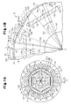
- Fig. 1A is a front cross-sectional view of a stator and a rotor of a motor according to a first embodiment embodying the present invention;
- Fig. 1B is a partially enlarged front cross-sectional view of Fig. 1A;
- Fig. 2 is a front cross-sectional view of the stator and the rotor of Fig. 1A;
- Fig. 3 is a perspective view of the stator of Fig. 1A;
- Fig. 4 is a view showing a wave winding of the windings in the stator of Fig. 1A;
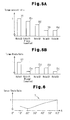
- Fig. 5A is a graph showing a FEM (Finite Element Method) analysis example of the torque constant of the
rotor 15 and the first to the fourthcomparative rotors 21 to 24; - Fig. 5B is a graph showing the FEM analysis example of the torque ripple of the
rotor 15 and the first to the fourthcomparative rotors 21 to 24; - Fig. 6 is a graph showing a relationship between angular width A of
circumferential portions rotor 15 and the torque ripple. - Figs. 7(a1), 7(b1), 7(c1), 7(d1), 7(e1), and 7(f1) are graphs showing FEM (Finite Element Method) analysis examples of changes in magnetic flux of a single tooth when the angular range A is changed;
- Figs. 7 (a2), 7 (b2), 7 (c2), 7 (d2), 7 (e2), and 7 (f2) are graphs showing FEM (Finite Element Method) analysis examples of changes in the sum of magnetic fluxes at all the teeth when the angular range A is changed.
- Fig. 8A is a graph showing a FEM (Finite Element Method) analysis example of changes in magnetic flux of a single tooth of the
rotor 15 androtor 24 when the angular range A is 20°. - Fig. 8B is a graph showing a FEM (Finite Element Method) analysis example of changes in magnetic flux of a single tooth of the
rotor 15 androtor 24 when the angular range A is 20°. - Fig. 9A is a partial cross-sectional view.
- Fig. 9B is a partially enlarged cross-sectional view.
- Fig. 10A is a graph showing an appropriate range of the inter-bridge angle Θb.
- Fig. 10B is a graph showing an appropriate range of the angular width A.
- Fig. 10C is a graph showing an appropriate range of the depth Dh.
- Figs. 10D, 10E and 10F are graphs showing force acting on the teeth.
- Fig. 11A is a graph showing the force acting on the teeth;
- Fig. 11B is a graph showing the torque fluctuation;
- Fig. 12A is a partial front cross-sectional view showing a first
comparative rotor 21; - Fig. 12B is a partial front cross-sectional view showing a second
comparative rotor 22; - Fig. 12C is a partial front cross-sectional view showing a third
comparative rotor 23; - Fig. 12D is a partial front cross-sectional view showing a fourth
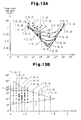
comparative rotor 24; - Fig. 13A is a graph showing the FEM analysis example of change in the torque ripple rate ratio Rx/Ri when the angular width A of the
rotor 15 is changed; - Fig. 13B is a graph showing determination of an appropriate range of combination of the angular width A and depth Dh for obtaining a torque ripple rate ratio Rx/Ri of less than 1;. and
- Fig. 14 is side cross-sectional view of an entire compressor to which the present invention is applied.
- A first embodiment of the present invention will now be described with reference to Figs. 1 to 12D.
- As shown in Fig. 1A, a
stator 11 includes anannular stator core 12 and acoil 13 arranged inslots 122 formed between a plurality ofteeth 121 arranged along the inner periphery of thestator core 12. In the present embodiment, the quantities of theteeth 121 andslots 122 are each eighteen. Theslots 122 are arranged at an equal pitch (equiangular pitch) in the circumferential direction of theannular stator 11. As shown in Fig. 2, thestator core 12 is formed by stacking a plurality ofcore plates 14, which are magnetic bodies (steel plates). Thecoil 13 arranged in theslot 122 is wound into a wave winding. - Generally, the following relational equation is satisfied when expressing the number of poles as p (integer), the number of phases as m (integer), the number of slots per phase for each pole as q (every 0.5, such as q=0.5, 1, 1.5, 2, 2.5, ···), and the number of slots of the stator as K.

- For instance, in a case in which there are three phases and q = 1, the relationship between the number of slots K and the number of poles p is four poles and twelve slots, six poles and eighteen slots, eight poles and twenty-four slots, and so on. In a case in which there are three phases and q = 1.5, the relationship between the number of slots K and the number p of poles is four poles and eighteen slots, six poles and twenty-seven slots, eight poles and thirty-six slots, and so on.
- The wave winding for six poles and eighteen slots will be described with reference to Figs. 3 and 4. In the wave winding of the
stator 11, a U-phase coil (indicated byreference character 13U), which is connected to aU-phase terminal 101 of aninverter 10, extends through a group of first slots (indicated byreference character 122U). A V-phase coil (indicated byreference character 13V), which is connected to a V-phase terminal 102 of theinverter 10, extends through a group of second slots (indicated byreference character 122V), and a W-phase coil (indicated byreference character 13W), which is connected to theterminal 103 of the W-phase of theinverter 10 extends through a group of third slots (indicated byreference character 122W). The portions of thecoils stator 11 that can be seen in this drawing. The portions of thecoils stator 11 that cannot be seen in this drawing. The joined part of the solid line portion and the broken line portion of thecoils slots coil - As shown in Fig. 1A, a
rotor 15 includes arotor core 16 and a plurality of flatpermanent magnets rotor core 16. The plurality ofpermanent magnets rotor core 16 is formed by stacking a plurality ofcore plates 14 made of magnetic bodies (steel plates). Ashaft hole 161 extends through the center of therotor core 16. An output shaft (not shown), which extends through theshaft hole 161, is fixed to therotor core 16. - As shown in Fig. 1A, plural sets of the first
permanent magnet 17A and the secondpermanent magnet 17B are fitted into accommodatingholes 162 extending through therotor core 16 parallel to theshaft hole 161. Thepermanent magnets rotor core 16 as magnetic poles that are adjacent in the circumferential direction of therotor 15. The magnetic poles of twopermanent magnets rotor 15 differ from each other. That is, thepermanent magnets - Each
permanent magnet magnetic pole end 171, a secondmagnetic pole end 172, and amagnetic pole center 173 located between the firstmagnetic pole end 171 and the secondmagnetic pole end 172. Aradial line 151A of therotor 15 extending through the flatmagnetic pole center 173 of thepermanent magnet 17A is orthogonal to thepermanent magnet 17A. Similarly, aradial line 151B of therotor 15 extending through the flatmagnetic pole center 173 of thepermanent magnet 17B is orthogonal to thepermanent magnet 17B. The radial lines 151A, 151B connecting to the rotational axis C of therotor 15 are spaced by equiangular intervals (60°) about the rotational axis C. Thepermanent magnets rotor 15 by an equal distance. Further, thepermanent magnets rotor 15. - An
opening 163 is provided in each of the two opposite ends (in the vicinity of the magnetic pole ends 171, 172) of theaccommodating hole 162. A magnetic path shortcircuit prevention opening 163 is defined in each of the two opposite ends of thepermanent magnets permanent magnets accommodating hole 162. - As shown in Fig. 1B,
circumferential portions 19A, 19b are defined on the outer circumference of therotor 15. Thecircumferential portions 19A, 19b each have radius R and extend about the rotational axis C with an angular width A. The associatedradial lines circumferential portion radial line 151A intersects thecircumferential center 191 of thecircumferential portion 19A, and theradial line 151B intersects thecircumferential center 191 of thecircumferential portion 19B. That is, the angular width between aradial line 152, which extends through afirst edge 192 of eachcircumferential portion radial line radial line 153, which extends through asecond edge 193 of eachcircumferential portion radial line first edge 192 and thesecond edge 193 about the rotational axis C is referred as a virtual circumferential surface E... - The
center 191 of eachcircumferential portion radial line circumferential portions circumferential portions magnetic pole center 173 of themagnetic magnets - The angular width (angular width about the rotational axis C of the rotor 15) Θ of the pitch of the plurality of (18 pieces of)
slots 122 arranged at an equal pitch in the circumferential direction of thestator 11 is 20°. The angular width A of thecircumferential portions slots 122 arranged at an equal pitch in the circumferential direction of thestator 11. - The
circumferential portion 19A corresponding to thepermanent magnet 17A and thecircumferential portion 19B corresponding to thepermanent magnet 17B are spaced apart from each other. Eachcircumferential portion 19A is connected to the adjacentcircumferential portion 19B by aconvex portion 20 bulging outward in the radial direction of therotor 15. - The
convex portions 20 bridging over the edge 193 (or 192) of thecircumferential portion 19A and the edge 192 (or 193) of thecircumferential portion 19B are an arcuate circumferential surface having a radius that is larger than the radius R of thecircumferential portions convex portions 20 are of identical shape and size. Accordingly, theconvex portions 20 project so as to be located inward than the circumferential surface E of the radius R including thecircumferential portions rotor 15 within a range outward of a plane H connecting theedge 192 and theedge 193. In other words, theconvex portions 20 project radially outward of therotor 15 within a region between the circumferential surface E and the plane H (except for sections immediately above the circumferential surface E and on the plane H). Moreover, a straight line J connecting two given points of the convex portions 20 (for instance, points 202, 203 shown in Fig. 1A) [shown in Fig. 1A] is located further inward than theconvex portion 20. - In Fig. 1B, the arcuate circumferential surface and the plane H that comprise the
convex portions 20 are each shown as an intersecting portion (that is, an intersecting curve) with a virtual plane (sheet of the drawing) that is orthogonal to the axis of the rotational axis C (hereinafter also referred to as "rotational axis C"). Hereinafter, the plane H may also be referred to as straight line H, and the arcuate circumferential surface comprising theconvex portions 20 as convex arcuate curve H1. - The
tip 201 of theconvex portion 20 corresponds to a magneticpole switching part 164 located between the firstpermanent magnet 17A and the secondpermanent magnet 17B. The gap G between theteeth 121 and the outer circumference of therotor 15 becomes largest at a portion corresponding to the magneticpole switching part 164, which is located between two adjacentpermanent magnets rotor 15 becomes largest at a portion corresponding to the magneticpole switching part 164. The distance between the outer circumference of therotor 15 and the rotational axis C is thus minimal at the portion corresponding to the gap G. - The bar graph of Fig. 5A shows an example in which the torque constant is obtained through FEM (Finite Element Method) analysis using the
rotor 15 of the present embodiment androtors rotor 15 of the present embodiment androtors stators 11 of each of therotors permanent magnets rotors - Common conditions of analysis of these examples obtained through FEM (Finite Element Method) analysis are as follows: the
width 17W of thepermanent magnets circumferential portions circumferential portions teeth 121 as shown in Fig. 9A] = 0.5 mm, number of poles p = 6, and number of slots = p × 3 (= 18). - The outer circumference of the
rotor 21 in Fig. 12A is the circumferential surface E of the radius R. The outer circumference of therotor 22 in Fig. 12B is comprised by thecircumferential portions circumferential portion 19A andcircumferential portion 19B. The outer circumference of therotor 23 in Fig. 12C is comprised by thecircumferential portions concave portion 231 connecting between adjacentcircumferential portion 19A andcircumferential portion 19B. Theconcave portion 231 is an arcuate surface that concaves inward than the plane H. The outer circumference of therotor 24 in Fig. 12D has a shape bridging over a sinusoidal circumferential surface (sinusoidal portion 241) in which the radius of therotor 24 becomes minimum at a position of a magneticpole switching part 164 between the adjacentpermanent magnets magnetic pole center 173 between magnetic pole ends 171, 172. The length ofradial lines rotor 24 is set to be larger than the minimum radius of therotor 22 and to be smaller than the minimum radius of therotor 15. - Bar B1 in the graph of Fig. 5A is represented with the torque constant of the
rotor 21 in Fig. 12A being defined as 1. Bar Bo in the graph of Fig. 5A represents the torque constant of therotor 15 of the present embodiment as a proportion to bar B1. Bar B2 in the graph of Fig. 5A represents the torque constant of therotor 22 of Fig. 12B as a proportion to bar B1. Bar B3 in the graph of Fig. 5A represents the torque constant of therotor 23 of Fig. 12C as a proportion to bar B1. Bar B4 in the graph of Fig. 5A represents the torque constant of therotor 24 of Fig. 12D as a proportion to bar B1. - Bar D1 in the graph of Fig. 5B is represented with the torque ripple of the
rotor 21 being defined as 1. Bar Do in the graph of Fig. 5B represents the torque ripple of therotor 15 of the present embodiment as a proportion to bar D1. Bar D2 in the graph of Fig. 5B represents the torque ripple of therotor 22 as a proportion to bar D1. Bar D3 in the graph of Fig. 5B represents the torque ripple of therotor 23 as a proportion to bar D1. Bar D4 in the graph of Fig. 5B represents the torque ripple of therotor 24 as a proportion to bar D1. - Curve T in the graph of Fig. 6 shows a relationship between the angular width A of the
circumferential portions rotor 15 and the torque ripple. The curve T is obtained through FEM (Finite Element Method), and conditions of analysis as identical to those of Fig. 5A and Fig. 5B. The abscissa axis represents the angular width A about the rotational axis C of therotor 15 and the ordinate axis a torque ripple ratio with the torque ripple of therotor 21 of Fig. 12A (angular width A = 60°) being defined as 1. - The curve L1 in the graph of Fig. 7(al) shows changes in magnetic flux of a
single tooth 121 when the angular width A of thecircumferential portions single tooth 121 when the angular width A of thecircumferential portions single tooth 121 when the angular width A of thecircumferential portions single tooth 121 when the angular width A of thecircumferential portions - The curve Q1 in the graph of Fig. 7(a2) shows changes in the summation of magnetic fluxes of all the
teeth 121 when the angular width A of thecircumferential portions teeth 121 when the angular width A of thecircumferential portions teeth 121 when the angular width A of thecircumferential portions teeth 121 when the angular width A of thecircumferential portions - The curve Lo in the graph of Fig. 8A shows changes in magnetic flux of a
single tooth 121 when the angular width A of thecircumferential portions single tooth 121 when the outer circumferential surface of the rotor is formed by a sinusoidal curve [see Fig. 12D]. The curve Yo in the graph of Fig. 8B shows changes in the summation of magnetic fluxes of all theteeth 121 when the angular width A of thecircumferential portions single tooth 121 when the circumferential surface of the rotor is formed by a sinusoidal curve [see Fig. 12D]. Curves Lo, X and lines Yo, Z have been obtained through FEM (Finite Element Method) analysis, and conditions of analysis are identical to those of Figs. 5A and 5B. - Fig. 9A shows a convex arcuate
portion radial line 154 connecting the tip 201 (the middle of theconvex portion 20 between thefirst edge 192 and thesecond edge 193 of thecircumferential portions convex portion 20 the rotational axis C. That is, the convex arcuateportion radial line 154 extends so as to bisect theconvex portion 20 in the circumferential direction. The length of the convexportion radial line 154 is the minimum distance between theconvex portion 20 and the rotational axis C. Hereinafter, the minimum distance (i.e., length of the convex portion radial line 154) between theconvex portion 20 and the rotational axis C is referred to as the minimum radius Rmin. Dh denotes the difference between amiddle position 190 of the virtual circumferential surface E and thetip 201. Themiddle position 190 bisects the virtual circumferential surface E between thefirst edge 192 and thesecond edge 193. Further, thetip 201 and themiddle position 190 lie along an extension of the convex arcuateportion radial line 154. Dh represents the difference between the radius R of thecircumferential portions - The
radial line 155 in Fig. 9B is a radial line connecting a middle position Ho and a rotational axis C that equally divides the plane H into two in the circumferential direction, and overlaps convex arcuateradial line 154. The length of theradial line 155 is a minimum radius of the plane H (shortest length of the radial line from among the radial lines connecting the plane H and the rotational axis C). Hereinafter, the minimum radius of plane H is referred to as minimum radius Hr [shown in Fig. 9A]. Dmax represents a linear distance between the middle position Ho andmiddle position 190 and represents a difference between the radius R and the minimum radius Hr. Hereinafter, Dmax is referred to as virtual maximum difference Dmax. Virtual maximum difference Dmax=R × {1 - cos([(360°/p) - A]/2)} is true, wherein depth Dh is smaller than the virtual maximum difference Dmax. - The
arc 20E in Figs. 9A and 9B is a part of a circle that is concentric with the arcuateconvex portions 20. Apoint 165 is a contact between a wall surface defining anopening 163 that comprises a part of anaccommodating hole 162 accommodating thepermanent magnet 17A and thearc 20E, andpoint 166 is a contact between a wall surface defining aopening 163 that comprises a part ofaccommodating hole 162 accommodating thepermanent magnet 17B and thearc 20E.Line 156 represents a radial line related to aconvex portion 20 that passes through thecontact 165 and that connects the circular center of theconvex portion 20 and the convex portion 20 (convex arcuate radial line connecting the circular center of theconvex portion 20 and the convex portion 20).Line 157 represents a radial line related to aconvex portion 20 that passes through thecontact 166 and that connects the circular center of theconvex portion 20 and the convex portion 20 (convex arcuate radial line connecting the circular center of theconvex portion 20 and the convex portion 20). Bmin1 represents a linear distance between thecontact 165 between the wall surface defining theopening 163 that comprises a part of theaccommodating hole 162 in thepermanent magnet 17A and the convexradial line 156 and anintersection 204 of the convex arcuateradial line 156 and theconvex portion 20. Bmin2 represents a linear distance between thecontact 166 between the wall surface defining theopening 163 that comprises a part of theaccommodating hole 162 in thepermanent magnet 17B and the convexradial line 157 and anintersection 205 of the convex arcuateradial line 157 and theconvex portion 20. The linear distances Bmin1 and Bmin2 represent a shortest length of straight lines from among straight lines connecting the wall surface defining theaccommodating hole 162 and theconvex portion 20 and satisfy Bmin1 = Bmin2. In other words, spacing Br1 between thecontact 165 and theintersection 204 becomes a minimum interval between the wall surface defining theaccommodating hole 162 and theconvex portion 20, and spacing Br2 between thecontact 166 and theintersection 205 becomes a minimum interval between the wall surface defining theaccommodating hole 162 and theconvex portion 20. Hereinafter, the spacing Br1 is referred to as a first minimum spacing Br1, and the spacing Br2 as a second minimum spacing Br2. Further, thecontact 165 is referred to as a firstinitial point 165 of the first minimum spacing Br1 and thecontact 166 is referred to as a secondinitial point 166 of the second minimum spacing Br2. - Θb represents the angular width between a
radial line 158, which connects the rotational axis C and the firstinitial point 165, and aradial line 159, which connects the rotational axis C and the secondinitial point 166. That is, Θb represents the angular width between the firstinitial point 165 and the secondinitial point 166 about the rotational axis C. The firstinitial point 165 is located on one of the adjacentaccommodating holes 162 that is separated by the first minimum spacing Br1 from theconvex portion 20. The secondinitial point 166 is located on the other one of theaccommodating holes 162 that is separated by the second minimum spacing Br2 from theconvex portion 20. Here, Θb is referred to as inter-bridge angle Θb. - In the illustrated case, the
initial points - In this respect, where the first
initial point 165 that provides the first minimum spacing Br1 exists in plurality, the firstinitial point 165 closest to themagnetic pole center 173 of thepermanent magnet 17A is employed, and where the secondinitial point 166 that provides the second minimum spacing Br2 exists in plurality, the secondinitial point 166 closest to themagnetic pole center 173 of thepermanent magnet 17B is employed. In other words, whereinitial points initial points opening 163 that comprises a part of theaccommodating hole 162 and thearc 20E are in linear contact in the circumferential direction of thearc 20E, an infinite number ofinitial points initial point 165 closest to themagnetic pole center 173 of thepermanent magnet 17A and the secondinitial point 166 closest to themagnetic pole center 173 of thepermanent magnet 17B will be employed also in such instance. - The graph of Fig. 11A shows the relationship between the rotation position of the rotor and the force acting on any one of the
teeth 121. The waveform Δ shows an ideal example. The waveform Δ and the horizontal axis form an isosceles triangle. The base of which isosceles triangle shows that the angular spacing between the starting end and the terminating end on the horizontal axis is 40°. A horizontal line TΔ shown in the graph of Fig. 11B is obtained by synthesizing such waveform Δ relating to all theteeth 121. That is, if the waveform of the force acting on onetooth 121 is waveform Δ, the output torque becomes constant (TΔ), and the torque ripple becomes zero. - The waveform Eλ in the graph of Fig. 11A shows the relationship between the rotation position of the first
comparative rotor 21 of Fig. 12A and the force acting on any one of theteeth 121 of the firstcomparative rotor 21. The synthesized waveform Te shown in the graph of Fig. 11B is obtained by synthesizing such waveform Eλ related to all theteeth 121 of the firstcomparative rotor 21. That is, if the force acting on onetooth 121 is the force shown by the waveform Eλ, the output torque in which the torque ripple is not zero is obtained. That is, the torque ripple of the rotating electric machine becomes smaller as the shape of the waveform Eλ becomes closer to the shape of the waveform A. - With regards to the
rotor 21 shown in Fig. 12A, the torque ripple rate Ri is calculated from the result of the FEM analysis conducted under the above common analysis conditions and a condition of inter-bridge angle Θb = 5.2°. The torque ripple rate Ri is a value obtained by dividing the torque ripple (size of fluctuation width of the output torque) by an average value of the output torque. The torque ripple rate R1 of therotor 15 is smaller than the torque ripple rate resulting from the FEM analysis under the above common analysis conditions and the condition of the inter-bridge angle Θb = 10° for the firstcomparative rotor 21 of Fig. 12A. A ratio Rx/Ri of a certain torque ripple rate Rx with respect to the torque ripple rate Ri of the FEM analysis result under the above common analysis conditions and the condition of the inter-bridge angle being Θb = 5.2°, using the firstcomparative rotor 21 of Fig. 12A is hereinafter referred to as a torque ripple rate ratio. The torque ripple rate ratio Rx/Ri is directly proportional to the torque ripple rate Rx. - The inter-bridge angles Θb = 10°, 5.2° represent maximum angular widths from among angular widths that are formed by minimum spacings between one of a pair of adjacent
accommodating holes 162 and the circumferential surface E of the radius R and minimum spacings between the other one of the pair of adjacentaccommodating holes 162 and the circumferential surface E of the radius R about a rotating axis of therotor 21. - The graph of Fig. 10A shows an example in which changes in the torque ripple rate ratio Rx/Ri in which inter-bridge angles Θb are varied using
rotor 15 are obtained through FEM (Finite Element Method) analysis. The abscissa axis represents values of the inter-bridge angle Θb while the ordinate axis represents values of the torque ripple rate ratio Rx/Ri. The black dots in the graph represent actual data obtained through FEM analysis. - The graph of Fig. 10B shows examples in which changes in the torque ripple rate ratio Rx/Ri in which angular widths A are varied using
rotor 15 are obtained through FEM (Finite Element Method) analysis. The abscissa axis represents values of the angular width A while the ordinate axis represents values of the torque ripple rate ratio Rx/Ri. The black dots in the graph represent actual data obtained through FEM analysis. - The graph of Fig. 10C shows an example in which changes in the torque ripple rate ratio Rx/Ri in which depths Dh are varied using
rotor 15 are obtained through FEM (Finite Element Method) analysis. The abscissa axis represents values of depth Dh while the ordinate axis represent values of the torque ripple rate ratio Rx/Ri. The black dots in the graph represent actual data obtained through FEM analysis. - Common conditions of analysis in these examples obtained through FEM (Finite Element Method) analysis are: the
width 17W of thepermanent magnets circumferential portions circumferential portions teeth 121 shown in Fig. 9A] = 0.5 mm, number of poles p = 6, and number ofslots 122=p × 3(= 18). - Conditions of analysis other than the above common conditions of analysis in the FEM analysis of Fig. 10A are angular width A = 26° and depth Dh = 0.5 mm. According to the FEM analysis example of Fig. 10A, when the inter-bridge angle Θb is set to be in the range of 0° < Θb ≤ 10°, the torque ripple rate ratio Rx/Ri can be suppressed to be less than 1. When the inter-bridge angle Θb is set to be in the range of 0° < Θb ≤ 8°, the torque ripple rate ratio Rx/Ri can be suppressed to be less than 0.75. When the inter-bridge angle Θb is set to be in the range of 0° < Θb ≤ 6°, the torque ripple rate ratio Rx/Ri can be suppressed to be less than 0.5. Particularly an inter-bridge angle Θb of 5.2° is optimal in sufficiently exploiting effects of reducing the torque ripple rate and securing strength between magnetic poles.
- Conditions of analysis other than the above common conditions of analysis in the FEM analysis of Fig. 10B are depth Dh = 0.5 mm and inter-bridge Θb = 5.2°. According to the FEM analysis example of Fig. 10B, when the angular width A is set to be in the range of 14° ≤ A ≤ 34°, the torque ripple rate ratio Rx/Ri can be suppressed to be less than 1.
- When the angular width A is set to be in the range of 17° ≤ A ≤ 30°, the torque ripple rate ratio Rx/Ri can be suppressed to be less than 0.75. When the angular width A is set to be in the range of 24° ≤ A ≤ 28°, the torque ripple rate ratio Rx/Ri can be suppressed to be less than 0.5. Particularly A = 26° is optimal in sufficiently exploiting effects of reducing the torque ripple rate.
- Conditions of analysis other than the above common conditions of analysis in the FEM analysis of Fig. 10C are angular width A = 26° and inter-bridge Θb = 5.2°. According to the FEM analysis example of Fig. 10C, when the depth Dh is set to be in the range of 0 < Dh ≤ 1 mm, the torque ripple rate ratio Rx/Ri can be suppressed to be less than 1.
- When the depth Dh is set to be in the range of 0.2 mm ≤ Dh ≤ 0.8 mm, the torque ripple rate ratio Rx/Ri can be suppressed to be less than 0.75.
- When the depth Dh is set to be in the range of 0.4 mm ≤ Dh ≤ 0.6 mm, the torque ripple rate ratio Rx/Ri can be suppressed to be less than 0.5. Particularly Dh = 0.5 mm is optimal in sufficiently exploiting effects of reducing the torque ripple rate.
- The waveform Λ1 in the graph of Fig. 10D shows a relationship between rotating positions of the
rotor 15 and force acting on onesingle tooth 121 when the inter-bridge angle is defined to be Θb = 5.2° in the FEM analysis example of Fig. 10A. The waveform Λ2 in the graph of Fig. 10E shows a relationship between rotating positions of therotor 15 and force acting on onesingle tooth 121 where the angular width is defined to be A = 26° in the FEM analysis example of Fig. 10B. The waveform Λ3 in the graph of Fig. 10F shows a relationship between rotating positions of therotor 15 and force acting on onesingle tooth 121 where the depth is defined to be Dh = 0.5 mm in the FEM analysis example of Fig. 10C. The torque ripple rate of the synthesized waveform of waveform Λ1 related to all theteeth 121 is quite small. Similarly, the torque ripple rate of the synthesized waveform of waveform Λ2 related to all theteeth 121 is quite small, and the torque ripple rate of the synthesized waveform of waveform Λ3 related to all theteeth 121 is quite small. - The FEM analysis example of Fig. 10A has been performed under the condition for the angular width being A = 26° and that for the depth being Dh = 0.5 mm, wherein changes in the value of the angular width A or the depth Dh result in changes in the torque ripple rate ratio Rx/Ri. In other words, when the value for the angular width is changed from 26° to another value, the torque ripple rate ratio Rx/Ri tends to increase, and when the value for the depth Dh is changed from 0.5 mm to another value, the torque ripple rate ratio Rx/Ri tends to increase. However, when the value of the angular width A or the value of the depth Dh is suitably changed, the torque ripple rate ratio Rx/Ri can be set to less than 1 for inter-bridge angles Θb set in the range of 0° < Θb < 10°. Similarly, when the value of the angular width A or the value of the depth Dh is suitably changed, the torque ripple rate ratio Rx/Ri can be set to less than 0.75 for inter-bridge angles Θb set in the range of 0° < Θb < 8°. Similarly, when the value of the angular width A or the value of the depth Dh is suitably changed, the torque ripple rate ratio Rx/Ri can be set to less than 0.5 for inter-bridge angles Θb set in the range of 0° < Θb < 6°.
- The FEM analysis example of Fig. 10B has been performed under the condition for the inter-bridge angles being Θb = 5.2° and that for the depth being Dh = 0.5 mm, wherein changes in the value of the inter-bridge angle Θb or the depth Dh result in changes in the torque ripple rate ratio Rx/Ri. In other words, when the value for the inter-bridge angle Θb is changed from 5.2° to a larger value, the torque ripple rate ratio Rx/Ri tends to increase, and when the value for the depth Dh is changed from 0.5 mm to another value, the torque ripple rate ratio Rx/Ri tends to increase. However, when the value of the inter-bridge angle Θb or the value of the depth Dh is suitably changed, the torque ripple rate ratio Rx/Ri can be set to less than 1 for angular widths set in the range of 14° < A <34°. Similarly, when the value of the inter-bridge angle Θb or the value of the depth Dh is suitably changed, the torque ripple rate ratio Rx/Ri can be set to less than 0.75 for angular widths set in the range of 17° < A < 30°. Similarly, when the value of the inter-bridge angle Θb or the value of the depth Dh is suitably changed, the torque ripple rate ratio Rx/Ri can be set to less than 0.5 for angular widths set in the range of 24° < A < 28°.
- The FEM analysis example of Fig. 10C has been performed under the condition for the inter-bridge angles being Θb = 5.2° and that for the angular width being A = 26°, wherein changes in the value of the inter-bridge angle Θb or the angular width A result in changes in the torque ripple rate ratio Rx/Ri. In other words, when the value for the inter-bridge angle Θb is increased from 5.2°, the torque ripple rate ratio Rx/Ri tends to increase, and when the value for the angular width A is changed from 26° to another value, the torque ripple rate ratio Rx/Ri tends to increase. However, when the value of the inter-bridge angle Θb or the value of the angular width A is suitably changed, the torque ripple rate ratio Rx/Ri can be set to less than 1 for depths Dh set in the range of 0 < Dh < 1 mm. Similarly, when the value of the inter-bridge angle Θb or the value of the angular width A is suitably changed, the torque ripple rate ratio Rx/Ri can be set to less than 0.75 for depths Dh set in the range of 0.2 mm < Dh < 0.8 mm. Similarly, when the value of the inter-bridge angle Θb or the value of the angular width A is suitably changed, the torque ripple rate ratio Rx/Ri can be set to less than 0.5 for depths Dh set in the range of 0.4 mm < Dh < 0.6 mm.
- The angles of the angular widths A and depths Dh represented by the above-indicated equalities and inequalities correspond to cases in which R = 25.5 mm and number of poles p = 6 are true. However, when the radius R is not 25.5 mm or the number of poles p is not 6, Dh should be substituted by Dhr that is represented by Dhr = Dh × 25.5/R, and A should be substituted by A × p/6.
- Ranges of the angular widths A and the depth Dh with which the torque ripple rate ratio Rx/Ri becomes less than 1 will now be explained with reference to Fig. 13.
- The graph of Fig. 13A shows examples in which changes in the torque ripple rate ratio Rx/Ri in which angular widths A are varied using
rotor 15 are obtained through FEM (Finite Element Method) analysis. The abscissa axis represents values of the angular widths A while the ordinate axis represents values of the torque ripple rate ratio Rx/Ri. The black dots in the graph represent actual data obtained through FEM analysis. - The group of actual data Γ(0.1), Γ(0.2), Γ(0.3), Γ(0.4), Γ(0.5), Γ(0.6), Γ(0.8), Γ(1), Γ(1.2) and Γ(1.4) in the graph of Fig. 13A indicates data obtained under conditions for the depth Dh being 0.1, 0.2, 0.3, 0.4, 0.5, 0.6, 0.8, 1, 1.2, 1.4 (in units of mm) in this order, the above common conditions of analysis, and the condition for the inter-bridge angle Θb being 5.2°.
- The graph of Fig. 13B is an explanatory view prepared for determining suitable ranges of combination of the angular widths A and the depth Dh on the basis of the graph of Fig. 13B. The ordinate axis of Fig. 13B represents angular width A while the abscissa axis represents depth Dh. The group of black dots shown in Fig. 13B represents actual data from among the group of actual data Γ(0.1), Γ(0.2), Γ(0.3), Γ(0.4), Γ(0.5), Γ(0.6), Γ(0.8), Γ(1), Γ(1.2) and Γ(1.4) with which the torque ripple rate ratio Rx/Ri becomes less than 1.
- The curve Ω represents upper limits for the angular widths A and depths Dh, wherein while the
convex portions 20 can be formed through the angular widths A downward of the curve Ω and the depths Dh leftward of the curve Ω but theconvex portions 20 cannot be formed through the angular widths A upward of the curve Ω and the depths Dh rightward of the curve Ω. Straight lines F, Σ are straight lines set for limiting the torque ripple rate ratio Rx/Ri to less than 1. The region enclosed by the curve Ω, the straight lines F, Σ and the ordinate axis is a region in which the torque ripple rate ratio Rx/Ri becomes less than 1. - The curve Ω is given by the following equation (2).

- Straight line F is given by the following equation (3).

- Straight-line Σ is given by the following equation (4).

- Gathering from the above equations (2) to (4), the torque ripple rate ratio Rx/Ri can be set to less than 1 when the angular widths A and depths Dh are set in the range given by the following equation (1-0).

- While equation (1-0) corresponds to a case in which R = 25.5 mm is true, this equation (1-0) can be expanded to the following equation (1) by defining Dhr = Dh × 25.5/R also when the radius R is not 25.5 mm.

- The first embodiment has the advantages described below.
- (1-1) As apparent from the graph of Fig. 5A, the torque constant for the
rotor 15 is not much different from the torque constant for the firstcomparative rotor 21 in which the outer circumference has a constant radius (= R). The torque constant for therotor 15 is greater than the torque constant for each of the second to the fourthcomparative rotors 22 to 24. That is, the lowering of torque for each of the second to the fourthcomparative rotors 22 to 24 is greater than for therotor 15, in particular, the lowering of torque for the third and the fourthcomparative rotors - As apparent from the graph of Fig. 5B, the torque ripple for the
rotor 15 is greatly lowered compared to the torque ripple for the firstcomparative rotor 21 in which the outer circumference has a constant radius (= R). The torque ripple for each of the second to the fourthcomparative rotor 22 to 24 is also small compared to the torque ripple for the firstcomparative rotor 21, but the torque ripple for therotor 15 is small compared to the torque ripple for the second and the thirdcomparative rotors comparative rotor 24 has about the same size as the torque ripple for therotor 15, but the torque for the fourthcomparative rotor 24 is greatly lowered compared to therotor 15, as apparent from the graph of Fig. 5A. - According to the graph of Fig. 8A, the magnetic flux changes are small for both of the
rotor 15 of the present embodiment and therotor 24 of Fig. 12D. However, according to the graph of Fig. 8B, the total magnetic flux of therotor 15 according to the present embodiment is larger than that of therotor 24 of Fig. 12D, and the FEM analysis result of Fig. 8B indicates that therotor 15 of the present embodiment is more advantaged than therotor 24 of Fig. 12D. - As apparent from the FEM analysis result shown in Fig. 5A and Fig. 5B, the
rotor 15 excels in suppressing the size of the torque and the torque fluctuation than the other first to the fourthcomparative rotors 21 to 24. The configuration of having a minimum gap between theteeth 121 of thestator 11 and the outer circumference of therotor 15 across the entirecircumferential portions convex portion 20 that smoothes the magnetic flux fluctuation at the outer circumferential surface of therotor 15 contributes to suppressing the torque fluctuation and also contributes to avoiding the lowering of the torque. That is, the result that therotor 15 excels in suppressing the size of the torque and the torque fluctuation than the other first to the fourthcomparative rotors 21 to 24 is provided by the configuration of connecting the adjacentcircumferential portions convex portion 20. - (1-2) The
convex portions 20 are formed by a convex arcuate curve H1 having a radius larger than the radius R of thecircumferential portions rotor 15 is suitable for suppressing torque pulsation. - Further, when the convex arcuate curves H1, of which the radius is larger than the radius R of the
circumferential portions edge 192 of thecircumferential portion 19A and theedge 193 of thecircumferential portion 19B, the convex arcuate curve H1 becomes convex towards outside in the radial direction within a region between the circumferential surface E and the plane H (except for sections immediately above the circumferential surface E and on the plane H). Accordingly, the convex arcuate curves H1 (arcuate circumferential surface) are a suitable curve (curved surface) in forming the outer circumferential surface of therotor 15 that is convex towards outside in the radial direction within the region between the circumferential surface E and the plane H (except for sections immediately above the circumferential surface E and on the plane H). - (1-3) As it is apparent from the FEM analysis result of Fig. 6, the torque ripple is minimum when the angular width A of the
circumferential portions circumferential portions slot 122 around the rotational axis C of therotor 15 are made equal to each other. - In other words, an arrangement in which the angular width A of the
circumferential portions slot 122 around the rotational axis C of therotor 15 are made equal to each other is particularly suitable for reducing the torque ripple. - (1-4) The analysis results of Figs. 5A, 5B, and 6 is obtained on the assumption that the
circumferential portions circumferential portions - (1-5) The maximum gap between the
teeth 121 and the outer circumference of therotor 15 is a gap G corresponding to the magneticpole switching part 164 located between two adjacentpermanent magnets pole switching part 164 being the largest contributes to alleviating sudden fluctuation in the magnetic flux density and suppressing torque fluctuation. - (1-6) The structure using wave winding of three phases for the winding method of the
stator 11 is advantageous in suppressing vibration. - (1-7) In a permanent magnet embedment rotating electric machine comprising arcuate circumferential surface shaped
convex portions 20 formed by the convex arcuate curve H1 and astator 11 having arotor 15 arranged as p=6 and 18slots 122, an arrangement in which the inter-bridge angle Θb is set to be in the range of 0° < Θb ≤ 10° is effective and preferable in suppressing the torque ripple rate. An arrangement in which the inter-bridge angle Θb is set to be in the range of 0° < Θb ≤ 8° is more effective in suppressing the torque ripple rate ratio Rx/Ri, that is the torque ripple rate. An arrangement in which the inter-bridge angle Θb is set to be in the range of 0° < Θb ≤ 6° is more effective in suppressing the torque ripple rate. An inter-bridge angle Θb of 5.2° is particularly preferable. An arrangement in which the angular width A is set to 26° and the depth Dh to 0.5 mm is even more preferable in sufficiently exploiting effects of reducing the torque ripple rate. - (1-8) In a permanent magnet embedment rotating electric machine comprising arcuate circumferential surface shaped
convex portions 20 formed by the convex arcuate curve H1 and astator 11 having arotor 15 arranged as p = 6 and 18slots 122, an arrangement in which the depth Dh is set to be in the range of 0 < Dh ≤ 1 mm is effective in suppressing the torque ripple rate ratio Rx/Ri, that is, the torque ripple rate. An arrangement in which the depth Dh is set to be in the range of 0.2 mm ≤ Dh ≤ 0.8 mm is more effective in suppressing the torque ripple rate. An arrangement in which the depth Dh is set to be in the range of 0.4 mm ≤ Dh ≤ 0.6 mm is more effective in suppressing the torque ripple rate. A depth Dh of 0.5 mm is particularly preferable. An arrangement in which the angular width A is set to 26°and the inter-bridge angle Θb of 5.2° is even more preferable in sufficiently exploiting effects of reducing the torque ripple rate. - An arrangement in which the inter-bridge angle Θb is set to 5.2° and the angular width A is set to 26° is preferable in suppressing the torque ripple rate ratio Rx/Ri, that is the torque ripple rate.
- (1-9) In a permanent magnet embedment rotating electric machine comprising arcuate circumferential surface shaped
convex portions 20 formed by the convex arcuate curve H1 and astator 11 having arotor 15 arranged as p = 6 and 18slots 122, an arrangement in which the angular width A is set to be in the range of 14° ≤ A ≤ 34° is effective in suppressing the torque ripple rate ratio Rx/Ri, that is the torque ripple rate. An arrangement in which the angular width A is set to be in the range of 17° ≤ A ≤30° is more effective in suppressing the torque ripple rate. An arrangement in which the angular width A is set to be in the range of 24° ≤ A ≤ 28° is more effective in suppressing the torque ripple rate. An angular width A of 26° is particularly preferable. - (1-10) An arrangement in which the angular width A is set to 26°, the depth Dh to 0.5 mm and the inter-bridge angle Θb of 5.2° is particularly preferable in sufficiently exploiting effects of reducing the torque ripple rate and securing strength between magnetic poles.
- (1-11) In the afore-mentioned sections (1-8), (1-9) and (1-10), the same advantages can be achieved even when Dh is substituted by Dhr and A by A × p/6.
- (1-12) In an arrangement in which the angular widths A and the depths Dh are set in the range given by equation (1), values obtained by dividing torque ripples by an average of output torques (torque ripple rate) will be smaller when compared to cases of rotating electric
machines employing rotor 21 having a constant outer circumferential radius. - It should be apparent to those skilled in the art that the present invention may be embodied in many other specific forms without departing from the spirit or scope of the invention. Particularly, it should be understood that the present invention may be embodied in the following forms.
- (1) The total number of
permanent magnets - (2) The present invention may be applied to rotating electric machines with four poles and twelve slots, six poles and twenty-seven slots, eight poles and twenty-four slots, and so on. This would have the same advantages as the above embodiments.
- (3) The present invention may be applied to a rotating electric machine including a
rotor 15 having twopermanent magnets permanent magnets permanent magnets - (4) As shown in Fig. 14, the present invention may be applied to an enclosed
electric compressor 30. Theelectric compressor 30 is a scroll type electric compressor. Therotor 15 of the rotating electric machine M is attached to the rotating shaft 32, and thestator 11 of the rotating electric machine M is fixed to the inner surface of themotor housing 35. The rotating shaft 32 of the rotating electric machine M rotates amovable scroll 31 of the electric compressor 30 (compression operation). This rotation reduces the volume of acompression chamber 34, which is defined between afixed scroll 33 and themovable scroll 31 that serves as a compression operation body. Coolant is drawn into themotor housing 35 from an external coolant circuit (not shown) and sent through asuction port 36 into thecompression chamber 34. The coolant in thecompression chamber 34 is then forced out of adischarge valve 38 from adischarge port 37 and discharged into adischarge chamber 39. The coolant in thedischarge chamber 39 then flows out into the external coolant circuit to flow back into themotor housing 35. An enclosed compressor refers to the rotating electric machine M being enclosed in a container integrally welded with thecompressor 30.
The rotating electric machine M of the present invention is superior in that it has low pulsation (low vibration) and is suitable for application to the enclosedelectric compressor 30. The demand for reducing noise and vibration without lowering the average value of the output torque is strong for vehicle enclosed electric compressors. The permanent magnet embedment rotating electric machine M satisfies such demands. - (5) The winding method of the stator may also be distributed winding wherein the same advantages can be achieved also in such an instance.
- (6) The present invention is also applicable to rotating electric machines employing concentrated winding such as 6-pole 9-slots wherein the same advantages can be achieved also in such an instance.
A plurality of convex portions (20) are located inside of a virtual circumferential surface (E). Each convex portion (20) connects an adjacent pair of circumferential portions (19A, 19B) with each other. Each convex portion (20) is an arcuate curve (H1) bulging radially outward. Each convex portion (20) defines a minimum radius (Rmin). A difference between a radius R and the minimum radius (Rmin) is a depth Dh. Dhr = Dh × 25.5/R. A range of an angular width A in relation to circumferential portion (19A, 19B) and a range of the depth Dh are set by the following expression (1),
Claims (20)
- A permanent magnet embedment rotating electric machine (M), comprising:an annular stator (11);a plurality of teeth (121) arranged on an inner circumference of the stator (11), a slot (122) is defined between each adjacent pair of the teeth (121);a plurality of coils (13), each coil (13) being arranged in one of the slots (122);a rotor (15) located inside of the stator (11), the rotor (15) defining a rotational axis (C), a virtual circumferential surface (E) about the rotational axis (C), and an outer circumference;a plurality of permanent magnets (17A, 17B) embedded inside the rotor (15), the permanent magnets (17A, 17B) defining a number of poles p, each of the permanent magnets (17A, 17B) having a magnetic pole center (173),the rotating electric machine (M) being characterized in that the outer circumference has a plurality of circumferential portions (19A, 19B), the circumferential portions (19A, 19B) being included in the virtual circumferential surface (E), and each of the circumferential portion (19A, 19B) defining an angular width A and a radius R relative to the rotational axis (C),wherein each of the circumferential portions (19A, 19B) corresponds to the magnetic pole center (173), and wherein the circumferential portions (19A, 19B), which correspond to the permanent magnets (17A, 17B), respectively, are spaced from each other; and
wherein a plurality of convex portions (20) are located inside of the virtual circumferential surface (E), each convex portion (20) connecting an adjacent pair of the circumferential portions (19A, 19B) with each other, each convex portion (20) being an arcuate curve (H1) bulging radially outward, wherein each convex portion (20) defines a minimum radius (Rmin), which is a minimum value of a distance between the rotational axis (C) and the convex portion (20), wherein the difference between the radius R and the minimum radius (Rmin) is a depth Dh, where Dhr = Dh × 25.5/R, and wherein the range of the angular width A and the range of the depth Dh are set by the following expression (1),
- The rotating electric machine (M) according to claim 1, characterized in that the rotor (15) includes:a plurality of accommodating holes (162) for accommodating the respective permanent magnets (17A, 17B), the accommodating holes (162) including a first accommodating hole (162) and a second accommodating hole (162), which are adjacent to each other;a first minimum spacing (Br1) defining the minimum spacing between a first accommodating hole (162) and the convex portion (20), wherein the first minimum spacing (Br1) has a first initial point (165) that is adjacent to the first accommodating hole (162); anda second minimum spacing (Br2) defining a minimum spacing between the second accommodating hole (162) and the convex portion (20), wherein the second minimum spacing (Br2) has a second initial point (166) that is adjacent to the second accommodating hole (162),wherein the first initial point (165) and the second initial point (166) define an inter-bridge angle Θb in relation to the rotational axis (C), wherein the range of the inter-bridge angle Θb is set by the expression: 0 < Θb ≤ 10°.
- The rotating electric machine (M) according to claim 1 or 2,
characterized in that the permanent magnets (17A, 17B) are located so as to alternately have different polarities in the circumferential direction. - The rotating electric machine (M) according to any one of claims 1 to 3,
characterized in that the slots (122) are arranged at an equal pitch in the circumferential direction of the stator (11). - The rotating electric machine (M) according to any one of claims 1 to 4,
characterized in that the circumferential portions (19A, 19B) are arranged at an equal pitch in the circumferential direction of the stator (11). - The rotating electric machine (M) according to any one of claims 1 to 5,
characterized in that the rotor (15) has a magnetic pole switching part (164) located between an adjacent pair of the permanent magnets (17A, 17B), and
wherein a gap (G) between the outer circumference of the rotor (15) and the teeth (121) is largest at a portion corresponding to the magnetic pole switching part (164). - The rotating electric machine (M) according to any one of claims 1 to 6,
characterized in that the coils (13) are wound about the stator (11) into a wave winding. - The rotating electric machine (M) according to any one of claims 1 to 7,
characterized in that the number of poles p is set to six. - The rotating electric machine (M) according to any one of claims 1 to 8,
characterized in that the number (K) of the slots (122) is set to eighteen. - The rotating electric machine (M) according to any one of claims 1 to 9,
characterized in that the rotor (15) defines a radial line (151A, 151B) that extends in a radial direction from the rotational axis (C), and
wherein the permanent magnets (17A, 17B) are each formed as a flat plate that is perpendicular to the radial line (151A, 151B). - The rotating electric machine (M) according to any one of claims 1 to 10,
characterized in that the distances between the permanent magnets (17A, 17B) and the rotational axis (C) are equal to each other. - A permanent magnet embedment rotating electric machine (M), comprising:an annular stator (11);a plurality of teeth (121) arranged on an inner circumference of the stator (11), a slot (122) is defined between each adjacent pair of the teeth (121);a plurality of coils (13), each coil (13) being arranged in one of the slots (122);a rotor (15) located inside of the stator (11), the rotor (15) defining a rotational axis (C), a virtual circumferential surface (E) about the rotational axis (C), and an outer circumference;a plurality of permanent magnets (17A, 17B) embedded inside the rotor (15), each of the permanent magnets (17A, 17B) having a magnetic pole center (173), wherein each of the circumferential portions (19A, 19B) corresponds to the magnetic pole center (173), and wherein the circumferential portions (19A, 19B), which correspond to the permanent magnets (17A, 17B), respectively, are spaced from each other; andthe rotating electric machine (C) being characterized in thatthe outer circumference has a plurality of circumferential portions (19A, 19B), the circumferential portions (19A, 19B) being included in the virtual circumferential surface (E), and each of the circumferential portions (19A, 19B) defining a radius R relative to the rotational axis (C),
wherein a plurality of convex portions (20) are located inside of the virtual circumferential surface (E), each convex portion (20) connecting an adjacent pair of the circumferential portions (19A, 19B) with each other, each convex portion (20) being an arcuate curve (H1) bulging radially outward, wherein each convex portion (20) defines a minimum radius (Rmin), which is a minimum value of a distance between the convex portion (20) and the rotational axis (C), wherein the difference between the radius R and the minimum radius (Rmin) is a depth Dh, where Dhr = Dh × 25.5/R, and wherein the range of the depth Dh is set by the following expression: 0 < Dhr ≤ 1 mm. - The rotating electric machine (M) according to claim 2,
characterized in that each of the circumferential portions (19A, 19B) define an angular width A in relation to the rotational axis (C), and the permanent magnets (17A, 17B) define a number of poles p, and
wherein the range of the angular width A is set by the expression: 14° × 6/p ≤ A ≤ 34° × 6/p. - The rotating electric machine (M) according to claim 12,
characterized in that each of the circumferential portions (19A, 19B) define an angular width A in relation to the rotational axis (C), and the permanent magnets (17A, 17B) define a number of poles p, and
wherein the range of the angular width A is set by the expression: 14° × 6/p ≤ A ≤ 34° × 6/p. - The rotating electric machine (M) according to claim 13,
characterized in that the angular width A is set by the expression: 26° × 6/p, and
wherein the depth Dhr is set to 0.5 mm. - The rotating electric machine (M) according to claim 14,
characterized in that the rotor (15) includes:a plurality of accommodating holes (162) for accommodating the respective permanent magnets (17A, 17B), the accommodating holes (162) including a first accommodating hole (162) and a second accommodating hole (162), which are adjacent to each other;a first minimum spacing (Br1) defining the minimum spacing between a first accommodating hole (162) and the convex portion (20), wherein the first minimum spacing (Br1) has a first initial point (165) that is adjacent to the first accommodating hole (162); anda second minimum spacing (Br2) defining a minimum spacing between the second accommodating hole (162) and the convex portion (20), wherein the second minimum spacing (Br2) has a second initial point (166) that is adjacent to the second accommodating hole (162),wherein the first initial point (165) and the second initial point (166) define an inter-bridge angle Θb in relation to the rotational axis (C), and
wherein the angular width A is set by the expression 26° × 6/p, and the inter-bridge angle Θb is set to 5.2°. - The rotating electric machine (M) according to claim 15,
characterized in that the inter-bridge angle Θb is set to 5.2°. - The rotating electric machine (M) according to claim 16,
characterized in that the depth Dhr is set to 0.5 mm. - A motor (M) for a car air conditioner, characterized in that the motor (M) includes the rotating electric machine (M) according to any one of claims 1 to 18.
- An enclosed electric compressor, characterized by:the motor (M) according to claim 19;a rotating shaft (32) driven by the motor (M);a compression chamber (34); anda compression operation body (31) that executes compression of gas in the compression chamber (34) on the basis of rotation of the rotating shaft (32), thereby compressing and discharging the gas.
Applications Claiming Priority (1)
| Application Number | Priority Date | Filing Date | Title |
|---|---|---|---|
| JP2006054092A JP4793027B2 (en) | 2006-02-28 | 2006-02-28 | Permanent magnet embedded rotary electric machine, motor for car air conditioner and hermetic electric compressor |
Publications (2)
| Publication Number | Publication Date |
|---|---|
| EP1826885A2 true EP1826885A2 (en) | 2007-08-29 |
| EP1826885A3 EP1826885A3 (en) | 2014-07-02 |
Family
ID=38069318
Family Applications (1)
| Application Number | Title | Priority Date | Filing Date |
|---|---|---|---|
| EP07103149.6A Withdrawn EP1826885A3 (en) | 2006-02-28 | 2007-02-27 | Rotating electrical machine with embedded permanent magnets, motor for car air conditioner, and closed electric compressor |
Country Status (5)
| Country | Link |
|---|---|
| US (1) | US7652405B2 (en) |
| EP (1) | EP1826885A3 (en) |
| JP (1) | JP4793027B2 (en) |
| KR (1) | KR100902534B1 (en) |
| CN (1) | CN101043157B (en) |
Cited By (3)
| Publication number | Priority date | Publication date | Assignee | Title |
|---|---|---|---|---|
| EP2395633A3 (en) * | 2010-06-11 | 2014-06-04 | Hitachi Appliances, Inc. | Displacement compressor |
| EP2619456A4 (en) * | 2010-09-20 | 2016-08-10 | Hanon Systems | COMPRESSOR DRIVEN BY ELECTRIC MOTOR FOR VEHICLE |
| EP3955425A1 (en) * | 2008-10-16 | 2022-02-16 | Hitachi Astemo, Ltd. | Rotating electric machine and electric automobile |
Families Citing this family (25)
| Publication number | Priority date | Publication date | Assignee | Title |
|---|---|---|---|---|
| JP4793249B2 (en) * | 2006-04-20 | 2011-10-12 | 株式会社豊田自動織機 | Permanent magnet embedded rotary electric machine, motor for car air conditioner and hermetic electric compressor |
| JP5288698B2 (en) * | 2006-10-20 | 2013-09-11 | 株式会社東芝 | Permanent magnet type reluctance type rotating electrical machine |
| US7939982B2 (en) * | 2008-10-02 | 2011-05-10 | Nidec Motor Corporation | Motor with lobed rotor having uniform and non-uniform air gaps |
| CN101651395B (en) * | 2009-09-04 | 2012-05-30 | 湖北西浦电机科技有限责任公司 | Sine wave current self-starting three-phase rare earth permanent-magnetism synchronous motor |
| JP5434415B2 (en) * | 2009-09-14 | 2014-03-05 | 株式会社豊田自動織機 | Permanent magnet embedded rotary electric machine |
| DE102011107803B4 (en) * | 2010-07-21 | 2025-02-27 | Denso Corporation | MOTOR |
| JP4725684B1 (en) * | 2010-08-10 | 2011-07-13 | 株式会社安川電機 | Generator and wind power generation system |
| JP5418467B2 (en) * | 2010-11-02 | 2014-02-19 | 株式会社安川電機 | Rotating electric machine |
| US9172279B2 (en) * | 2011-02-04 | 2015-10-27 | Mitsubishi Electric Corporation | Automotive embedded permanent magnet rotary electric machine |
| CN103650293B (en) * | 2011-07-15 | 2016-05-04 | 三菱电机株式会社 | Permanent magnet embedded-type electric motivation, compressor, pressure fan and refrigerating air conditioning device |
| KR20130019088A (en) * | 2011-08-16 | 2013-02-26 | 엘지이노텍 주식회사 | Rotor core of motor |
| EP2800243B8 (en) * | 2011-12-26 | 2018-02-28 | Mitsubishi Electric Corporation | Rotor of permanent-magnet embedded motor, and compressor, blower, and refrigerating/air conditioning device using the rotor |
| US20130342065A1 (en) * | 2012-05-08 | 2013-12-26 | Asmo Co., Ltd. | Brushless motor and method for manufacturing brushless motor |
| JP6379462B2 (en) * | 2013-09-03 | 2018-08-29 | 富士電機株式会社 | Permanent magnet embedded rotary electric machine |
| CN105186816B (en) | 2015-07-16 | 2018-08-03 | 博格思众(常州)电机电器有限公司 | The composite structure of stator and rotor |
| CN107026524B (en) * | 2016-02-01 | 2021-06-01 | 德昌电机(深圳)有限公司 | Single-phase motor and rotor thereof |
| US10389196B2 (en) * | 2016-03-31 | 2019-08-20 | Nidec Motor Corporation | Spoked rotor with tapered pole segments and tapered ear recesses |
| DE102018112971A1 (en) | 2018-05-30 | 2019-12-05 | Hanon Systems | Permanent magnet synchronous motor and magnetic positioning system for a compressor of a vehicle air conditioning system |
| US11201512B2 (en) | 2019-07-23 | 2021-12-14 | Delta Electronics, Inc. | Rotor assembly and motor using same |
| US11575285B2 (en) * | 2020-12-09 | 2023-02-07 | Ford Global Technologies, Llc | Electric machine |
| US12512711B2 (en) * | 2021-02-16 | 2025-12-30 | Toyota Jidosha Kabushiki Kaisha | Rotor with magnet and embedding holes |
| JP7615847B2 (en) * | 2021-04-05 | 2025-01-17 | 株式会社デンソー | Rotor and rotating electric machine |
| TWI801840B (en) * | 2021-04-14 | 2023-05-11 | 東元電機股份有限公司 | Rotor structure with edge notches |
| US11646617B2 (en) * | 2021-08-30 | 2023-05-09 | Hiwin Mikrosystem Corp. | High-frequency rotating structure with permanent magnet rotor having grooves and magnetic barrier spaces |
| EP4148957A1 (en) * | 2021-09-09 | 2023-03-15 | Hiwin Mikrosystem Corp. | High-frequency rotating structure |
Family Cites Families (27)
| Publication number | Priority date | Publication date | Assignee | Title |
|---|---|---|---|---|
| JPH05191936A (en) | 1992-01-10 | 1993-07-30 | Toshiba Corp | Permanent magnet type rotor |
| US5864191A (en) | 1992-08-12 | 1999-01-26 | Seiko Epson Corporation | Efficient permanent magnet rotor for brushless motor |
| JPH07222384A (en) | 1994-01-27 | 1995-08-18 | Toshiba Corp | Permanent magnet type motor |
| KR19980075864A (en) * | 1997-04-02 | 1998-11-16 | 윤종용 | Brushless DC Motor |
| JP2000060091A (en) * | 1998-08-06 | 2000-02-25 | Ebara Corp | Dynamo electric machine |
| JP2000197292A (en) | 1998-10-21 | 2000-07-14 | Mitsubishi Electric Corp | Permanent magnet type rotor of permanent magnet type electric motor |
| DE19851883A1 (en) * | 1998-11-10 | 2000-05-18 | Siemens Ag | Permanent magnet polyphase-machine especially synchronous machine |
| JP2001069701A (en) | 1999-08-30 | 2001-03-16 | Mitsubishi Heavy Ind Ltd | Magnet motor |
| DE60141308D1 (en) * | 2000-03-31 | 2010-04-01 | Sanyo Electric Co | Synchronous motor with internal permanent magnet |
| JP3513467B2 (en) * | 2000-06-16 | 2004-03-31 | ファナック株式会社 | Synchronous motor rotor |
| JP2002095194A (en) | 2000-09-11 | 2002-03-29 | Daihatsu Motor Co Ltd | Embedded-magnet motor |
| TW538578B (en) * | 2000-09-13 | 2003-06-21 | Sanyo Electric Co | Synchronous motor with built-in type permanent magnet |
| JP2002136011A (en) | 2000-10-26 | 2002-05-10 | Fujitsu General Ltd | Permanent magnet motor |
| CN2452202Y (en) * | 2000-11-16 | 2001-10-03 | 沈阳工业大学 | Sinusoidal permanent magnetic magnetodensi wave-shape permasyn motor |
| ITTO20010182A1 (en) * | 2001-03-02 | 2002-09-02 | Fiat Ricerche | SYNCHRONOUS TYPE ELECTRIC MACHINE. |
| JP3899885B2 (en) * | 2001-10-05 | 2007-03-28 | 株式会社日立製作所 | Permanent magnet rotating electric machine |
| JP2003136011A (en) | 2001-10-31 | 2003-05-13 | Fujimori Gijutsu Kenkyusho:Kk | System for supplying chemical |
| JP2003219616A (en) * | 2002-01-23 | 2003-07-31 | Toyota Industries Corp | Electric motor for electric compressor, method for adjusting rotor balance thereof, and electric compressor |
| ATE311030T1 (en) * | 2002-03-22 | 2005-12-15 | Ebm Papst St Georgen Gmbh & Co | INNER ROTOR MOTOR |
| US7230359B2 (en) * | 2002-03-22 | 2007-06-12 | Ebm-Papst St. Georgen Gmbh & Co. Kg | Electric motor with poles shaped to minimize cogging torque |
| JP3852930B2 (en) * | 2003-02-27 | 2006-12-06 | アイチエレック株式会社 | Permanent magnet rotating machine |
| US7042127B2 (en) * | 2003-04-02 | 2006-05-09 | Nidec Sankyo Corporation | Permanent magnet embedded motor |
| JP3913205B2 (en) | 2003-09-10 | 2007-05-09 | アイチエレック株式会社 | Permanent magnet rotating machine |
| JP4319562B2 (en) * | 2004-02-27 | 2009-08-26 | 三菱電機株式会社 | Synchronous motor, hermetic compressor and fan motor |
| EP1713156B1 (en) * | 2005-04-14 | 2008-01-23 | Kabushiki Kaisha Toyota Jidoshokki | Rotating electric machine with embedded permanent magnets |
| KR101095556B1 (en) * | 2005-06-13 | 2011-12-19 | 삼성전자주식회사 | Permanent Magnet Electric Motor |
| JP4793249B2 (en) * | 2006-04-20 | 2011-10-12 | 株式会社豊田自動織機 | Permanent magnet embedded rotary electric machine, motor for car air conditioner and hermetic electric compressor |
-
2006
- 2006-02-28 JP JP2006054092A patent/JP4793027B2/en not_active Expired - Fee Related
-
2007
- 2007-02-27 EP EP07103149.6A patent/EP1826885A3/en not_active Withdrawn
- 2007-02-27 US US11/713,110 patent/US7652405B2/en not_active Expired - Fee Related
- 2007-02-27 KR KR1020070019838A patent/KR100902534B1/en not_active Expired - Fee Related
- 2007-02-28 CN CN2007100923897A patent/CN101043157B/en not_active Expired - Fee Related
Cited By (3)
| Publication number | Priority date | Publication date | Assignee | Title |
|---|---|---|---|---|
| EP3955425A1 (en) * | 2008-10-16 | 2022-02-16 | Hitachi Astemo, Ltd. | Rotating electric machine and electric automobile |
| EP2395633A3 (en) * | 2010-06-11 | 2014-06-04 | Hitachi Appliances, Inc. | Displacement compressor |
| EP2619456A4 (en) * | 2010-09-20 | 2016-08-10 | Hanon Systems | COMPRESSOR DRIVEN BY ELECTRIC MOTOR FOR VEHICLE |
Also Published As
| Publication number | Publication date |
|---|---|
| US20070200447A1 (en) | 2007-08-30 |
| CN101043157A (en) | 2007-09-26 |
| EP1826885A3 (en) | 2014-07-02 |
| US7652405B2 (en) | 2010-01-26 |
| JP2007236096A (en) | 2007-09-13 |
| JP4793027B2 (en) | 2011-10-12 |
| KR20070089630A (en) | 2007-08-31 |
| KR100902534B1 (en) | 2009-06-15 |
| CN101043157B (en) | 2010-12-15 |
Similar Documents
| Publication | Publication Date | Title |
|---|---|---|
| EP1826885A2 (en) | Rotating electrical machine with embedded permanent magnets, motor for car air conditioner, and closed electric compressor | |
| EP1848092B1 (en) | Permanent magnet embedment rotating electric machine, motor for car air conditioner, and enclosed electric compressor | |
| EP0823771B1 (en) | Motor | |
| EP2296259B1 (en) | Permanent magnet embedded rotating electrical machine | |
| EP2216885B1 (en) | Interior permanent magnet type brushless direct current motor and compressor having the same | |
| CN104810946B (en) | Permanent magnet type electric rotary machine and use its compressor | |
| CN102142722B (en) | Permanent magnet type rotary motor and compressor using the motor | |
| EP2876785B1 (en) | Interior permanent magnet motor | |
| EP1713156B1 (en) | Rotating electric machine with embedded permanent magnets | |
| JP2018074890A (en) | Rotary electric machine | |
| JP6018940B2 (en) | Rotor and motor | |
| JP2011015499A (en) | Rotor of electric motor | |
| JP5208662B2 (en) | Permanent magnet type rotating electric machine and compressor using the same | |
| US20240030761A1 (en) | Rotor and rotating electric machine | |
| CN110875658A (en) | Electric motors and compressors | |
| WO2010110150A1 (en) | Permanent magnet-embedded motor | |
| US11984763B2 (en) | Electric machines having a radially embedded permanent magnet rotor and methods thereof | |
| CN214506685U (en) | Stator core unit, stator core, motor and compressor | |
| JP4752587B2 (en) | Permanent magnet embedded rotary electric machine, motor for car air conditioner and hermetic electric compressor | |
| JP2011015500A (en) | Rotor of electric motor | |
| CN110875647B (en) | Stator, synchronous motor and compressor | |
| JP2026061816A (en) | Electric motors and compressors |
Legal Events
| Date | Code | Title | Description |
|---|---|---|---|
| PUAI | Public reference made under article 153(3) epc to a published international application that has entered the european phase |
Free format text: ORIGINAL CODE: 0009012 |
|
| 17P | Request for examination filed |
Effective date: 20070227 |
|
| AK | Designated contracting states |
Kind code of ref document: A2 Designated state(s): AT BE BG CH CY CZ DE DK EE ES FI FR GB GR HU IE IS IT LI LT LU LV MC NL PL PT RO SE SI SK TR |
|
| AX | Request for extension of the european patent |
Extension state: AL BA HR MK YU |
|
| PUAL | Search report despatched |
Free format text: ORIGINAL CODE: 0009013 |
|
| AK | Designated contracting states |
Kind code of ref document: A3 Designated state(s): AT BE BG CH CY CZ DE DK EE ES FI FR GB GR HU IE IS IT LI LT LU LV MC NL PL PT RO SE SI SK TR |
|
| AX | Request for extension of the european patent |
Extension state: AL BA HR MK RS |
|
| RIC1 | Information provided on ipc code assigned before grant |
Ipc: H02K 29/03 20060101ALI20140523BHEP Ipc: H02K 1/27 20060101AFI20140523BHEP |
|
| AKX | Designation fees paid |
Designated state(s): DE FR IT |
|
| AXX | Extension fees paid |
Extension state: HR Extension state: AL Extension state: BA Extension state: RS Extension state: MK |
|
| 17Q | First examination report despatched |
Effective date: 20150909 |
|
| STAA | Information on the status of an ep patent application or granted ep patent |
Free format text: STATUS: THE APPLICATION IS DEEMED TO BE WITHDRAWN |
|
| 18D | Application deemed to be withdrawn |
Effective date: 20160901 |