EP1826790A1 - Operation panel having flexible display - Google Patents
Operation panel having flexible display Download PDFInfo
- Publication number
- EP1826790A1 EP1826790A1 EP07003572A EP07003572A EP1826790A1 EP 1826790 A1 EP1826790 A1 EP 1826790A1 EP 07003572 A EP07003572 A EP 07003572A EP 07003572 A EP07003572 A EP 07003572A EP 1826790 A1 EP1826790 A1 EP 1826790A1
- Authority
- EP
- European Patent Office
- Prior art keywords
- flexible display
- operation panel
- mode
- key
- display
- Prior art date
- Legal status (The legal status is an assumption and is not a legal conclusion. Google has not performed a legal analysis and makes no representation as to the accuracy of the status listed.)
- Granted
Links
- 238000004519 manufacturing process Methods 0.000 description 3
- 230000005540 biological transmission Effects 0.000 description 2
- 238000009434 installation Methods 0.000 description 2
- 230000001771 impaired effect Effects 0.000 description 1
- 238000012905 input function Methods 0.000 description 1
- 239000004973 liquid crystal related substance Substances 0.000 description 1
- 238000003754 machining Methods 0.000 description 1
- 239000000463 material Substances 0.000 description 1
- 238000012986 modification Methods 0.000 description 1
- 230000004048 modification Effects 0.000 description 1
Images


Classifications
-
- H—ELECTRICITY
- H01—ELECTRIC ELEMENTS
- H01H—ELECTRIC SWITCHES; RELAYS; SELECTORS; EMERGENCY PROTECTIVE DEVICES
- H01H9/00—Details of switching devices, not covered by groups H01H1/00 - H01H7/00
- H01H9/02—Bases, casings, or covers
- H01H9/0214—Hand-held casings
-
- H—ELECTRICITY
- H04—ELECTRIC COMMUNICATION TECHNIQUE
- H04M—TELEPHONIC COMMUNICATION
- H04M1/00—Substation equipment, e.g. for use by subscribers
- H04M1/02—Constructional features of telephone sets
- H04M1/0202—Portable telephone sets, e.g. cordless phones, mobile phones or bar type handsets
- H04M1/026—Details of the structure or mounting of specific components
- H04M1/0266—Details of the structure or mounting of specific components for a display module assembly
- H04M1/0268—Details of the structure or mounting of specific components for a display module assembly including a flexible display panel
-
- H—ELECTRICITY
- H01—ELECTRIC ELEMENTS
- H01H—ELECTRIC SWITCHES; RELAYS; SELECTORS; EMERGENCY PROTECTIVE DEVICES
- H01H2217/00—Facilitation of operation; Human engineering
- H01H2217/022—Part of keyboard not operable
Definitions
- the present invention relates to an operation panel having an operation key area and a display area.
- An operation panel having a plurality of operation keys and a fixed display, must be provided with an operation key area required for operating all keys and a display area having a size sufficient to effectively indicate an image or information.
- a fixed display 102 and a plurality of operation keys 104 are arranged on a front face of a conventional operation panel 100 as shown in Fig. 9, a fixed display 102 and a plurality of operation keys 104 are arranged.
- Japanese Unexamined Patent Publication No. 8-166814 discloses a robot teaching operation panel provided with a liquid crystal display (LCD) having a touch panel function.
- LCD liquid crystal display
- an operation panel is as small as possible, as long as the operability and the visibility of the operation panel are not impaired, from the viewpoint of a production cost and the installation space for the operation panel.
- an operation panel as disclosed in Japanese Unexamined Patent Publication No. 8-166814 the display of which may also have an input function, is not necessarily provided with a considerable number of operation keys.
- an operation panel as shown in Fig. 9, having a large number of operation keys and a display on a front face thereof, cannot be downsized, due to the required size of the display and the number of the operation keys. As a result, it is difficult to effectively reduce the size of such an operation panel.
- an object of the present invention is to provide an operation panel capable of being effectively made smaller, while the operability and the visibility are maintained at a conventional level.
- an operation panel provided with a display area and a key operation area including first and second operation keys, the operation panel having a first operation mode in which both the first and second operation keys are used and a second operation mode in which the second operation key is not used, wherein the operation panel has a flexible display configured to be moved between first and second positions, the flexible display being positioned at the first position in the first operation mode such that the flexible display does not cover the first and second operation keys, and the flexible display being positioned at the second position in the second operation mode such that the flexible display covers the second operation key.
- the operation panel may further have a means for changing the position of the flexible display corresponding to the position of the second operation key.
- the operation panel may further have a means for disabling the second operation key covered by the flexible display in the second operation mode.
- the key operation area may further have a third operation key positioned between the first and second operation keys and the operation panel may further have a third operation mode in which only the first operation key is used.
- the flexible display is positioned at a third position between the first and second position, in the third operation mode, such that the flexible display covers the second and third operation keys.
- the operation panel may further have a means for changing the position of the flexible display corresponding to the position of the third operation key.
- the operation panel may further have a means for disabling the third operation key covered by the flexible display in the third operation mode.
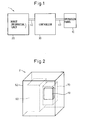
- Fig. 1 shows a schematic configuration of a robot system 1 including an operation panel 10 of the invention.
- the operation panel 10 is connected to a control part or a controller 30 via a cable 40.
- the controller 30 is connected to a robot 20 for controlling the robot. Accordingly, by operating the operation panel 10, the robot 20 may be taught or manually operated.
- Such a basic constitution or function may be the same as that of a conventional robot system.
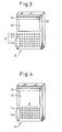
- Fig. 2 shows an example of a configuration of a machine tool 2 including the operation panel 10.
- the machine tool 2 has a cabinet 50 containing a machining section 60 and a controlling section 70.
- the operation panel 10 is attached to a front face of the cabinet 50. By operating the operation panel 10, a machining program may be inputted and/or the machine tool 2 may be manually operated.
- Such a basic constitution or function also may be the same as that of a conventional machine tool.
- Fig. 3 shows details of the operation panel 10 as shown in Figs. 1 and 2.
- the operation panel 10 a display area or a display means 12 made from a flexible material which may be repeatedly wound and unwound, and a plurality of operation keys 14 or an operation area for inputting various command to the operation panel 10.
- various types of flexible electric displays such as a display means 12 have been developed and the present invention utilizes the flexible display.
- the operation panel 10 has a storing part 16 capable of storing the flexible display 12 in a rolled state.
- the storing part 16 may be incorporated in a body of the operation panel 10.
- Each of the plurality of operation keys 14 may have a various size and the shape, corresponding to the function and/or application thereof.
- the operation keys 14 include a first operation key 14a, having a square shape, a second operation key 14b, having a circular shape, and a third operation key 14c, having a triangular shape, positioned between the first and second operation keys.
- the operation panel 10 has several operation modes, for example, a first mode in which all operation keys 14a, 14b and 14c are used, a second mode in which only the second operation key 14b is not used, and a third mode in which only the first operation key 14a is used.
- a first mode in which all operation keys 14a, 14b and 14c are used
- a second mode in which only the second operation key 14b is not used
- a third mode in which only the first operation key 14a is used.
- the display of the operation panel used in the second mode is required or desired to be larger than that used in the first mode
- the display used in the third mode is required or desired to be larger than that used in the second mode.
- Fig. 3 shows the operation panel 10 used in the first operation mode.
- the flexible display 12 is positioned at a first position, at which the flexible display is partially stored in the storing part 16 such that all operation keys may be operated or effectively inputted.
- the flexible display 12 may be withdrawn from the storing part 16 to a second position, at which the flexible display 12 covers the second operation key 14b so as to enlarge the display area, as shown in Fig. 4.
- the second operation key 14b is not used in the second mode. Therefore, the display area in the second mode may be enlarged relative to the first mode. Power supply to the flexible display and transmission and reception of a control signal to and from the display may be carried out in the storing part 16.
- the flexible display 12 may be further withdrawn from the storing part 16 to a third position, at which the flexible display 12 covers the second and third operation keys 14b and 14c so as to further enlarge the display area, as shown in Fig. 5.
- the second and third operation keys 14b and 14c are not used in the third mode. Therefore, the display area in the third mode may be enlarged relative to the second mode.
- the fixed panel In a conventional operation panel having a fixed display, the fixed panel must have size large enough to be used in the third mode requiring the largest display area, whereby the whole size of the operation panel is also enlarged.
- the operation panel of the present invention may be downsized, while maintaining the equivalent function of the conventional operation panel. Accordingly, the installation space and the production cost of the operation panel may be reduced.
- Fig. 6 shows a structure for holding the flexible display 12 at a certain position, after the flexible display is withdrawn to that position.
- the flexible display 12 has a tab 12a integrally formed with either side of a lower end of the flexible display 12.
- a hole 12b is formed on the tab 12a.
- protrusions 18 capable of engaging with the hole 12b are arranged on portions of the operation panel 10 corresponding to the position of the hole 12b. Due to this structure, the flexible display 12 may be held at a certain position by engaging the hole 12b with one of the protrusions 18. As shown in Fig. 6, by arranging a plurality of protrusions 18, the flexible display 12 may be held at desired positions including the first, second and third positions as described above.
- Figs. 7a and 7b another preferable structure for holding the flexible display 12 at a certain position.
- the operation panel 10 has a guide rail 20 capable of engaging with either side end of the flexible display 12.
- the guide rail 20 is configured such that the width of a groove 20a of the guide rail 20 for holding the flexible display 12 is substantially equal to the thickness of the side end of the flexible display. Due to this structure, the flexible display 12 may be held at an arbitrary position by a frictional force generated between the groove 20a and the side end of the flexible display 12.
- the storing part 16 of the operation panel 10 may store the flexible display 12 in a wound-up state or a folded state.
- the storing part 16 may be removed and a part of the flexible display 12 may extend along the upper face 10a so as to change the display area of the operation panel 10.
- Figs. 8a and 8b show the positions of the flexible display 12 used in the first and third operation modes, respectively.
- a flexible cable (not shown).
- the structure for holding the flexible display as shown in Fig.6 or 7 may be used.
- Figs. 8a and 8b schematically show the guide rail 20 similar to that of Fig. 7.
- the operation panel 10 has a means for disabling key input operation of a key, which is not to be used and covered by the flexible display 12, such as the second operation key in the second operation mode.
- a detector 22 Fig. 3 for detecting the length of the wound display 12 within the storing part 16
- the current operation mode of the operation panel 10 may be judged.
- key input operation against the key may be disabled by software control or hardware control.
- the current operation mode may be judged by using a contact sensor 24 arranged on the protrusion 18 as shown in Fig. 6 or another contact sensor 26 arranged on the guide rail 20 as shown in Fig. 7a.
- the second operation key which is not used in the second operation mode may be covered by the flexible display, whereby the display area of the operation panel in the second mode may be larger than that in the first mode. Therefore, it is unnecessary to enlarge the size of the operation panel in order to ensure a sufficiently wide area for the second operation mode. Accordingly, the operation panel may be effectively reduced in size and the production cost thereof may be reduced, while the operability and the visibility are maintained at the conventional level.
- the means for changing the position of the flexible display with the operation panel a sufficient display area may be obtained even when the operation mode is changed (or a unused key is changed). Further, due to the means for disabling a key covered by the flexible display, incorrect input of the key may be surely avoided.
Landscapes
- Engineering & Computer Science (AREA)
- Signal Processing (AREA)
- Push-Button Switches (AREA)
- Manipulator (AREA)
- Numerical Control (AREA)
- Devices For Indicating Variable Information By Combining Individual Elements (AREA)
Abstract

Description
- The present application claims priority from
Japanese Patent Application No. 2006-53273, filed on February 28, 2006 - The present invention relates to an operation panel having an operation key area and a display area.
- An operation panel, having a plurality of operation keys and a fixed display, must be provided with an operation key area required for operating all keys and a display area having a size sufficient to effectively indicate an image or information. For example, on a front face of a
conventional operation panel 100 as shown in Fig. 9, afixed display 102 and a plurality ofoperation keys 104 are arranged. Further,Japanese Unexamined Patent Publication No. 8-166814 - In general, it is advantageous that an operation panel is as small as possible, as long as the operability and the visibility of the operation panel are not impaired, from the viewpoint of a production cost and the installation space for the operation panel. At this point, an operation panel as disclosed in
Japanese Unexamined Patent Publication No. 8-166814 - Accordingly, an object of the present invention is to provide an operation panel capable of being effectively made smaller, while the operability and the visibility are maintained at a conventional level.
- To this end, according to the present invention, there is provided an operation panel provided with a display area and a key operation area including first and second operation keys, the operation panel having a first operation mode in which both the first and second operation keys are used and a second operation mode in which the second operation key is not used, wherein the operation panel has a flexible display configured to be moved between first and second positions, the flexible display being positioned at the first position in the first operation mode such that the flexible display does not cover the first and second operation keys, and the flexible display being positioned at the second position in the second operation mode such that the flexible display covers the second operation key.
- The operation panel may further have a means for changing the position of the flexible display corresponding to the position of the second operation key.
- Also, the operation panel may further have a means for disabling the second operation key covered by the flexible display in the second operation mode.
- The key operation area may further have a third operation key positioned between the first and second operation keys and the operation panel may further have a third operation mode in which only the first operation key is used. In this case, the flexible display is positioned at a third position between the first and second position, in the third operation mode, such that the flexible display covers the second and third operation keys.
- The operation panel may further have a means for changing the position of the flexible display corresponding to the position of the third operation key.
- Also, the operation panel may further have a means for disabling the third operation key covered by the flexible display in the third operation mode.
- The above and other objects, features and advantages of the present invention will be made more apparent by the following description of the preferred embodiments thereof, with reference to the accompanying drawings, wherein:
- Fig. 1 shows a schematic configuration of a robot system including an operation panel of the invention;
- Fig. 2 shows an example of a configuration of a machine tool including the operation panel of the invention;
- Fig. 3 shows a preferred embodiment of the operation panel used in a first operation mode;
- Fig. 4 shows the operation panel of Fig. 1 used in a second operation mode;
- Fig. 5 shows the operation panel of Fig. 1 used in a third operation mode;
- Fig. 6 shows an example of a constitution for holding a flexible display in place;
- Fig. 7a shows an example of another constitution for holding a flexible display in place
- Fig. 7b shows a b-b section of Fig. 7a;
- Figs. 8a and 8b show an operation panel without a storing part, indicating the position of the flexible display in the first and third operation modes, respectively; and
- Fig. 9 shows a schematic configuration of an operation panel of the prior art.
- Hereinafter, the present invention is described with reference to the drawings. First, Fig. 1 shows a schematic configuration of a
robot system 1 including anoperation panel 10 of the invention. Theoperation panel 10 is connected to a control part or acontroller 30 via acable 40. Thecontroller 30 is connected to arobot 20 for controlling the robot. Accordingly, by operating theoperation panel 10, therobot 20 may be taught or manually operated. Such a basic constitution or function may be the same as that of a conventional robot system. - Fig. 2 shows an example of a configuration of a
machine tool 2 including theoperation panel 10. Themachine tool 2 has acabinet 50 containing amachining section 60 and a controllingsection 70. Theoperation panel 10 is attached to a front face of thecabinet 50. By operating theoperation panel 10, a machining program may be inputted and/or themachine tool 2 may be manually operated. Such a basic constitution or function also may be the same as that of a conventional machine tool. - Fig. 3 shows details of the
operation panel 10 as shown in Figs. 1 and 2. Theoperation panel 10 a display area or a display means 12 made from a flexible material which may be repeatedly wound and unwound, and a plurality ofoperation keys 14 or an operation area for inputting various command to theoperation panel 10. These days, various types of flexible electric displays such as a display means 12 have been developed and the present invention utilizes the flexible display. Theoperation panel 10 has a storingpart 16 capable of storing theflexible display 12 in a rolled state. The storingpart 16 may be incorporated in a body of theoperation panel 10. Each of the plurality ofoperation keys 14 may have a various size and the shape, corresponding to the function and/or application thereof. In this embodiment, for clarity, theoperation keys 14 include afirst operation key 14a, having a square shape, a second operation key 14b, having a circular shape, and a third operation key 14c, having a triangular shape, positioned between the first and second operation keys. - The
operation panel 10 has several operation modes, for example, a first mode in which alloperation keys 14a, 14b and 14c are used, a second mode in which only the second operation key 14b is not used, and a third mode in which only thefirst operation key 14a is used. In addition, it is assumed that the display of the operation panel used in the second mode is required or desired to be larger than that used in the first mode, and that the display used in the third mode is required or desired to be larger than that used in the second mode. - Fig. 3 shows the
operation panel 10 used in the first operation mode. Theflexible display 12 is positioned at a first position, at which the flexible display is partially stored in the storingpart 16 such that all operation keys may be operated or effectively inputted. At this point, if the operation mode is required to be changed to the second mode, theflexible display 12 may be withdrawn from thestoring part 16 to a second position, at which theflexible display 12 covers the second operation key 14b so as to enlarge the display area, as shown in Fig. 4. As described above, the second operation key 14b is not used in the second mode. Therefore, the display area in the second mode may be enlarged relative to the first mode. Power supply to the flexible display and transmission and reception of a control signal to and from the display may be carried out in the storingpart 16. - Also, if the operation mode is required to be changed to the third mode, the
flexible display 12 may be further withdrawn from the storingpart 16 to a third position, at which theflexible display 12 covers the second and third operation keys 14b and 14c so as to further enlarge the display area, as shown in Fig. 5. As described above, the second and third operation keys 14b and 14c are not used in the third mode. Therefore, the display area in the third mode may be enlarged relative to the second mode. In a conventional operation panel having a fixed display, the fixed panel must have size large enough to be used in the third mode requiring the largest display area, whereby the whole size of the operation panel is also enlarged. On the contrary, the operation panel of the present invention may be downsized, while maintaining the equivalent function of the conventional operation panel. Accordingly, the installation space and the production cost of the operation panel may be reduced. - Fig. 6 shows a structure for holding the
flexible display 12 at a certain position, after the flexible display is withdrawn to that position. Theflexible display 12 has a tab 12a integrally formed with either side of a lower end of theflexible display 12. A hole 12b is formed on the tab 12a. On the other hand, on portions of theoperation panel 10 corresponding to the position of the hole 12b,protrusions 18 capable of engaging with the hole 12b are arranged. Due to this structure, theflexible display 12 may be held at a certain position by engaging the hole 12b with one of theprotrusions 18. As shown in Fig. 6, by arranging a plurality ofprotrusions 18, theflexible display 12 may be held at desired positions including the first, second and third positions as described above. - Figs. 7a and 7b another preferable structure for holding the
flexible display 12 at a certain position. As shown in Fig. 7a, theoperation panel 10 has aguide rail 20 capable of engaging with either side end of theflexible display 12. As shown in Fig. 7b, theguide rail 20 is configured such that the width of agroove 20a of theguide rail 20 for holding theflexible display 12 is substantially equal to the thickness of the side end of the flexible display. Due to this structure, theflexible display 12 may be held at an arbitrary position by a frictional force generated between thegroove 20a and the side end of theflexible display 12. - As described above, the storing
part 16 of theoperation panel 10 may store theflexible display 12 in a wound-up state or a folded state. However, as shown in Figs. 8a and 8b, when theoperation panel 10 is independent from the cabinet or the like and when anupper face 10a or a side face of theoperation panel 10 other than the operation area (the front face) has a relatively large area, the storingpart 16 may be removed and a part of theflexible display 12 may extend along theupper face 10a so as to change the display area of theoperation panel 10. Figs. 8a and 8b show the positions of theflexible display 12 used in the first and third operation modes, respectively. In this case, power supply to the flexible display and transmission and reception of a control signal to and from the display may be carried by using a flexible cable (not shown). In addition, also in this case, the structure for holding the flexible display as shown in Fig.6 or 7 may be used. Figs. 8a and 8b schematically show theguide rail 20 similar to that of Fig. 7. - It is advantageous that the
operation panel 10 has a means for disabling key input operation of a key, which is not to be used and covered by theflexible display 12, such as the second operation key in the second operation mode. For example, by arranging a detector 22 (Fig. 3) for detecting the length of thewound display 12 within the storingpart 16, the current operation mode of theoperation panel 10 may be judged. Then, when one or more keys should be disabled to be inputted in the current operation mode, key input operation against the key may be disabled by software control or hardware control. Otherwise, the current operation mode may be judged by using acontact sensor 24 arranged on theprotrusion 18 as shown in Fig. 6 or anothercontact sensor 26 arranged on theguide rail 20 as shown in Fig. 7a. - According to the operation panel of the invention, the second operation key which is not used in the second operation mode may be covered by the flexible display, whereby the display area of the operation panel in the second mode may be larger than that in the first mode. Therefore, it is unnecessary to enlarge the size of the operation panel in order to ensure a sufficiently wide area for the second operation mode. Accordingly, the operation panel may be effectively reduced in size and the production cost thereof may be reduced, while the operability and the visibility are maintained at the conventional level. In addition, by providing the means for changing the position of the flexible display with the operation panel, a sufficient display area may be obtained even when the operation mode is changed (or a unused key is changed). Further, due to the means for disabling a key covered by the flexible display, incorrect input of the key may be surely avoided.
- While the invention has been described with reference to specific embodiments chosen for the purpose of illustration, it should be apparent that numerous modifications could be made thereto, by one skilled in the art, without departing from the basic concept and scope of the invention.
Claims (6)
- An operation panel (10) provided with a display area (12) and a key operation area (14) including first and second operation keys (14a, 14b), the operation panel having a first operation mode in which both the first and second operation keys (14a, 14b) are used and a second operation mode in which the second operation key (14b) is not used,
characterized in that the operation panel (10) has a flexible display (12) configured to be moved between first and second positions, the flexible display (12) being positioned at the first position in the first operation mode such that the flexible display (12) do not cover the first and second operation keys (14a, 14b), and the flexible display (12) being positioned at the second position in the second operation mode such that the flexible display covers the second operation key (14b). - The operation panel according to claim 1, further comprising a means (12a, 12b, 18; 20) for changing the position of the flexible display (12) corresponding to the position of the second operation key (14b).
- The operation panel according to claim 1, further comprising a means (22; 24; 26) for disabling the second operation key (14b), covered by the flexible display (12), in the second operation mode.
- The operation panel according to claim 1, wherein the key operation area (14) further includes a third operation key (14c) positioned between the first and second operation keys (14a, 14b) and the operation panel (10) further has a third operation mode in which only the first operation key (14a) is used, and wherein the flexible display (12) is positioned at a third position between the first and second position, in the third operation mode, such that the flexible display (12) covers the second and third operation keys (14b, 14c).
- The operation panel according to claim 4, further comprising a means (12a, 12b, 18; 20) for changing the position of the flexible display (12) corresponding to the position of the third operation key (14c).
- The operation panel according to claim 4, further comprising a means (22; 24; 26) for disabling the third operation key (14c), covered by the flexible display (12), in the third operation mode.
Applications Claiming Priority (1)
| Application Number | Priority Date | Filing Date | Title |
|---|---|---|---|
| JP2006053273A JP4097674B2 (en) | 2006-02-28 | 2006-02-28 | Control panel with flexible display |
Publications (2)
| Publication Number | Publication Date |
|---|---|
| EP1826790A1 true EP1826790A1 (en) | 2007-08-29 |
| EP1826790B1 EP1826790B1 (en) | 2010-12-15 |
Family
ID=38016421
Family Applications (1)
| Application Number | Title | Priority Date | Filing Date |
|---|---|---|---|
| EP07003572A Ceased EP1826790B1 (en) | 2006-02-28 | 2007-02-21 | Operation panel having flexible display |
Country Status (5)
| Country | Link |
|---|---|
| US (1) | US20070200829A1 (en) |
| EP (1) | EP1826790B1 (en) |
| JP (1) | JP4097674B2 (en) |
| CN (1) | CN100480909C (en) |
| DE (1) | DE602007011132D1 (en) |
Families Citing this family (2)
| Publication number | Priority date | Publication date | Assignee | Title |
|---|---|---|---|---|
| CN102956161A (en) * | 2012-10-19 | 2013-03-06 | 京东方科技集团股份有限公司 | Appliance with flexible display screen |
| CN105690382A (en) * | 2014-12-12 | 2016-06-22 | 精工爱普生株式会社 | Robot control apparatus |
Citations (6)
| Publication number | Priority date | Publication date | Assignee | Title |
|---|---|---|---|---|
| JPH08166814A (en) | 1994-12-15 | 1996-06-25 | Fanuc Ltd | Teaching operation panel for robot |
| WO2000038332A1 (en) * | 1998-12-21 | 2000-06-29 | Intel Corporation | Electronic device with hidden keyboard |
| WO2001009872A1 (en) * | 1999-07-29 | 2001-02-08 | Interlink Electronics, Inc. | Remote computer input peripheral |
| GB2359690A (en) * | 1999-11-16 | 2001-08-29 | Nec Corp | Portable telephone apparatus with hinged and sliding elements |
| US20050250532A1 (en) * | 2004-05-06 | 2005-11-10 | Samsung Electronics Co., Ltd. | Sliding/swing-type portable apparatus having self-retaining function |
| JP2006053273A (en) | 2004-08-10 | 2006-02-23 | Ricoh Co Ltd | CONTENT GENERATION DEVICE, PROGRAM, AND RECORDING MEDIUM |
Family Cites Families (4)
| Publication number | Priority date | Publication date | Assignee | Title |
|---|---|---|---|---|
| FI103238B1 (en) * | 1997-02-21 | 1999-05-14 | Nokia Mobile Phones Ltd | Mobile communication devices |
| JP2005231010A (en) * | 2004-02-23 | 2005-09-02 | Fanuc Ltd | Display device |
| KR100663552B1 (en) * | 2004-06-10 | 2007-01-02 | 삼성전자주식회사 | Handheld Terminals with Mobility Keypads |
| US7558057B1 (en) * | 2005-06-06 | 2009-07-07 | Alex Naksen | Personal digital device with adjustable interface |
-
2006
- 2006-02-28 JP JP2006053273A patent/JP4097674B2/en not_active Expired - Fee Related
-
2007
- 2007-02-21 DE DE602007011132T patent/DE602007011132D1/en active Active
- 2007-02-21 EP EP07003572A patent/EP1826790B1/en not_active Ceased
- 2007-02-26 CN CNB2007100787498A patent/CN100480909C/en not_active Expired - Fee Related
- 2007-02-27 US US11/711,004 patent/US20070200829A1/en not_active Abandoned
Patent Citations (6)
| Publication number | Priority date | Publication date | Assignee | Title |
|---|---|---|---|---|
| JPH08166814A (en) | 1994-12-15 | 1996-06-25 | Fanuc Ltd | Teaching operation panel for robot |
| WO2000038332A1 (en) * | 1998-12-21 | 2000-06-29 | Intel Corporation | Electronic device with hidden keyboard |
| WO2001009872A1 (en) * | 1999-07-29 | 2001-02-08 | Interlink Electronics, Inc. | Remote computer input peripheral |
| GB2359690A (en) * | 1999-11-16 | 2001-08-29 | Nec Corp | Portable telephone apparatus with hinged and sliding elements |
| US20050250532A1 (en) * | 2004-05-06 | 2005-11-10 | Samsung Electronics Co., Ltd. | Sliding/swing-type portable apparatus having self-retaining function |
| JP2006053273A (en) | 2004-08-10 | 2006-02-23 | Ricoh Co Ltd | CONTENT GENERATION DEVICE, PROGRAM, AND RECORDING MEDIUM |
Also Published As
| Publication number | Publication date |
|---|---|
| EP1826790B1 (en) | 2010-12-15 |
| DE602007011132D1 (en) | 2011-01-27 |
| JP2007233605A (en) | 2007-09-13 |
| CN100480909C (en) | 2009-04-22 |
| CN101030075A (en) | 2007-09-05 |
| JP4097674B2 (en) | 2008-06-11 |
| US20070200829A1 (en) | 2007-08-30 |
Similar Documents
| Publication | Publication Date | Title |
|---|---|---|
| US7220941B2 (en) | Remote controller and control unit for a welding device | |
| JP4020171B2 (en) | Retractable display | |
| EP3677988B1 (en) | Display device and operating method thereof | |
| EP2360560A1 (en) | Mobile terminal device and key arrangement control method | |
| US8185846B2 (en) | Teaching box for use in robot, customization method, and robot system using the same | |
| JP4814761B2 (en) | Display device with small display | |
| JP4911786B2 (en) | Display system, display control apparatus, and computer program | |
| JP5863414B2 (en) | Operating device and movable machine control system | |
| US6075925A (en) | Control panel for image forming devices | |
| JP2009109943A (en) | Display device | |
| EP1826790B1 (en) | Operation panel having flexible display | |
| EP1055544B1 (en) | In-car switch controller | |
| US20050231332A1 (en) | Manual operating unit for robot | |
| EP2793480B1 (en) | Wall-mounted remote control | |
| JP4091612B2 (en) | Display device for injection molding machine | |
| US20140043338A1 (en) | Waveform display apparatus | |
| JP3985892B2 (en) | Fault note user interface for printing systems | |
| US20120041754A1 (en) | Electronic apparatus, method of controlling the electronic apparatus and tape print apparatus | |
| JP5888643B2 (en) | Operating device and movable machine control system | |
| US20170293827A1 (en) | Printing device | |
| JP5051277B2 (en) | In-vehicle device operation system | |
| US20090046066A1 (en) | Operating device for operating a machine tool, a production machine and/or a machine in the form of a robot | |
| KR200195702Y1 (en) | A wireless keyboard | |
| KR20010056568A (en) | Portable electronic book and method for driving the electronic book | |
| JP4580917B2 (en) | AV system |
Legal Events
| Date | Code | Title | Description |
|---|---|---|---|
| PUAI | Public reference made under article 153(3) epc to a published international application that has entered the european phase |
Free format text: ORIGINAL CODE: 0009012 |
|
| AK | Designated contracting states |
Kind code of ref document: A1 Designated state(s): AT BE BG CH CY CZ DE DK EE ES FI FR GB GR HU IE IS IT LI LT LU LV MC NL PL PT RO SE SI SK TR |
|
| AX | Request for extension of the european patent |
Extension state: AL BA HR MK YU |
|
| 17P | Request for examination filed |
Effective date: 20070802 |
|
| 17Q | First examination report despatched |
Effective date: 20071023 |
|
| AKX | Designation fees paid |
Designated state(s): DE |
|
| GRAP | Despatch of communication of intention to grant a patent |
Free format text: ORIGINAL CODE: EPIDOSNIGR1 |
|
| GRAS | Grant fee paid |
Free format text: ORIGINAL CODE: EPIDOSNIGR3 |
|
| GRAA | (expected) grant |
Free format text: ORIGINAL CODE: 0009210 |
|
| AK | Designated contracting states |
Kind code of ref document: B1 Designated state(s): DE |
|
| REF | Corresponds to: |
Ref document number: 602007011132 Country of ref document: DE Date of ref document: 20110127 Kind code of ref document: P |
|
| RAP2 | Party data changed (patent owner data changed or rights of a patent transferred) |
Owner name: FANUC CORPORATION |
|
| PLBE | No opposition filed within time limit |
Free format text: ORIGINAL CODE: 0009261 |
|
| STAA | Information on the status of an ep patent application or granted ep patent |
Free format text: STATUS: NO OPPOSITION FILED WITHIN TIME LIMIT |
|
| REG | Reference to a national code |
Ref country code: DE Ref legal event code: R082 Ref document number: 602007011132 Country of ref document: DE Representative=s name: WUESTHOFF & WUESTHOFF PATENT- UND RECHTSANWAEL, DE |
|
| 26N | No opposition filed |
Effective date: 20110916 |
|
| REG | Reference to a national code |
Ref country code: DE Ref legal event code: R082 Ref document number: 602007011132 Country of ref document: DE Representative=s name: WUESTHOFF & WUESTHOFF PATENT- UND RECHTSANWAEL, DE Effective date: 20111116 Ref country code: DE Ref legal event code: R081 Ref document number: 602007011132 Country of ref document: DE Owner name: FANUC CORPORATION, OSHINO-MURA, JP Free format text: FORMER OWNER: FANUC LTD., YAMANASHI, JP Effective date: 20111116 Ref country code: DE Ref legal event code: R081 Ref document number: 602007011132 Country of ref document: DE Owner name: FANUC CORPORATION, OSHINO, JP Free format text: FORMER OWNER: FANUC LTD., YAMANASHI, JP Effective date: 20111116 Ref country code: DE Ref legal event code: R081 Ref document number: 602007011132 Country of ref document: DE Owner name: FANUC CORPORATION, JP Free format text: FORMER OWNER: FANUC LTD., YAMANASHI, JP Effective date: 20111116 Ref country code: DE Ref legal event code: R082 Ref document number: 602007011132 Country of ref document: DE Representative=s name: WUESTHOFF & WUESTHOFF, PATENTANWAELTE PARTG MB, DE Effective date: 20111116 |
|
| REG | Reference to a national code |
Ref country code: DE Ref legal event code: R097 Ref document number: 602007011132 Country of ref document: DE Effective date: 20110916 |
|
| REG | Reference to a national code |
Ref country code: DE Ref legal event code: R082 Ref document number: 602007011132 Country of ref document: DE Representative=s name: WUESTHOFF & WUESTHOFF PATENT- UND RECHTSANWAEL, DE Effective date: 20120202 Ref country code: DE Ref legal event code: R081 Ref document number: 602007011132 Country of ref document: DE Owner name: FANUC CORPORATION, OSHINO-MURA, JP Free format text: FORMER OWNER: FANUC CORP., YAMANASHI, JP Effective date: 20120202 Ref country code: DE Ref legal event code: R081 Ref document number: 602007011132 Country of ref document: DE Owner name: FANUC CORPORATION, OSHINO, JP Free format text: FORMER OWNER: FANUC CORP., YAMANASHI, JP Effective date: 20120202 Ref country code: DE Ref legal event code: R081 Ref document number: 602007011132 Country of ref document: DE Owner name: FANUC CORPORATION, JP Free format text: FORMER OWNER: FANUC CORP., YAMANASHI, JP Effective date: 20120202 Ref country code: DE Ref legal event code: R082 Ref document number: 602007011132 Country of ref document: DE Representative=s name: WUESTHOFF & WUESTHOFF, PATENTANWAELTE PARTG MB, DE Effective date: 20120202 |
|
| PGFP | Annual fee paid to national office [announced via postgrant information from national office to epo] |
Ref country code: DE Payment date: 20210209 Year of fee payment: 15 |
|
| REG | Reference to a national code |
Ref country code: DE Ref legal event code: R119 Ref document number: 602007011132 Country of ref document: DE |
|
| PG25 | Lapsed in a contracting state [announced via postgrant information from national office to epo] |
Ref country code: DE Free format text: LAPSE BECAUSE OF NON-PAYMENT OF DUE FEES Effective date: 20220901 |