EP1826528A1 - Image measuring system, image measuring method and image measuring program - Google Patents
Image measuring system, image measuring method and image measuring program Download PDFInfo
- Publication number
- EP1826528A1 EP1826528A1 EP07004014A EP07004014A EP1826528A1 EP 1826528 A1 EP1826528 A1 EP 1826528A1 EP 07004014 A EP07004014 A EP 07004014A EP 07004014 A EP07004014 A EP 07004014A EP 1826528 A1 EP1826528 A1 EP 1826528A1
- Authority
- EP
- European Patent Office
- Prior art keywords
- measurement
- point
- points
- synthesized
- aft
- Prior art date
- Legal status (The legal status is an assumption and is not a legal conclusion. Google has not performed a legal analysis and makes no representation as to the accuracy of the status listed.)
- Granted
Links
Images




Classifications
-
- G—PHYSICS
- G01—MEASURING; TESTING
- G01B—MEASURING LENGTH, THICKNESS OR SIMILAR LINEAR DIMENSIONS; MEASURING ANGLES; MEASURING AREAS; MEASURING IRREGULARITIES OF SURFACES OR CONTOURS
- G01B11/00—Measuring arrangements characterised by the use of optical techniques
- G01B11/02—Measuring arrangements characterised by the use of optical techniques for measuring length, width or thickness
- G01B11/03—Measuring arrangements characterised by the use of optical techniques for measuring length, width or thickness by measuring coordinates of points
Definitions
- the present invention relates to an image measuring system, image measuring method and image measuring program provided with a nonstop measurement mode for moving an imaging means relative to a measurement stage that supports an object to be measured and taking in instantaneous image information without making a stop at a designated measurement location.
- a conventional CNC image measuring machine moves a measurement stage relative to an imaging means such as a CCD camera, as shown in Fig. 13, and makes a stop at a measurement location. Then, it adjusts the amount of illuminative light to acquire image information about an object to be measured, and applies image processing such as measuring tool setting and edge detection to the acquired image information, thereby executing a measurement at one measurement location.
- This measurement is repeatedly executed as Measurement 1, Measurement 2, ... at all measurement locations to complete measurements at required locations (hereinafter such the measurement mode is referred to as a "standard mode").
- an image measuring machine which has a measurement mode for measuring without making no stop of the measurement stage relative to the imaging means even at the measurement location (hereinafter such the measurement mode is referred to as a "nonstop measurement mode") ( JP 2004-535587A , paragraphs 0005-0006, Fig. 2).
- This image measuring machine irradiates the object with strobe illumination or uses a shuttered CCD camera to capture instantaneous image information without making no stop of the measurement stage at measurement locations as shown in Fig. 14. Then, it takes in the captured instantaneous image information for image measuring.
- This image measuring machine positions the CCD camera fast and roughly in the measurement region and, after deceleration, it takes in an image in a slow region.
- the above-described conventional image measuring machine has no problem if the measurement locations are arranged along a straight line. To the contrary, if they are not arranged along a straight line, when the speed of the measuring machine is kept constant to execute measurements at measurement locations, a problem may arise. Namely, a larger variation angle of the advancing direction, with a measurement pulse such as a square (a directional variation angle of 90o) or a Z-shape (a directional variation angle of 90o or more) , requires an addition of a larger acceleration to follow a turning location (hereinafter referred to as a bent point) and accordingly overloads the machine. This results in vibrations of the machine and causes shakes of subsequent captured images (deterioration of the image quality) and shakes of imaging positions, which deteriorate measurement accuracy of the image. In some cases, the overload may blow a protective fuse.
- the present invention has been made in consideration of such the problem and has an object to provide an image measuring system, image measuring method and image measuring program capable of preventing deterioration of measurement accuracy and of imposing no overload on any movement mechanism.
- the present invention provides an image measuring system for moving an imaging means relative to a measurement stage that supports an object to be measured and taking in instantaneous image information about the object without making a stop of the imaging means at any of a plurality of measurement locations, thereby performing image measuring.
- the system comprises a measurement point acquirer operative to acquire measurement points; a movement direction calculator operative to acquire a shortest path connecting between the measurement points and to calculate a movement direction on the shortest path; a synthesized direction calculator operative to calculate a synthesized direction resulted from synthesis of movement directions before and after the measurement point; a fore/aft-running point calculator operative to calculate a forerunning point at a position spaced a certain distance backward in the synthesized direction from the measurement point from which the synthesized direction is calculated and to calculate an aft-running point at a position spaced a certain distance forward in the synthesized direction from the measurement point from which the synthesized direction is calculated; a way point calculator operative to calculate a plurality of way points arranged on a path smoothly connecting the aft-running point to the forerunning point related to a measurement point located one point posterior in a measurement sequence to the measurement point from which the aft-running point is calculated, such that the path follows the synthe
- the present invention also provides an image measuring method for moving an imaging means relative to a measurement stage that supports an object to be measured and taking in instantaneous image information about the object without making a stop of the imaging means at any of a plurality of measurement locations, thereby performing image measuring.
- the method comprises a measurement point acquisition step of acquiring measurement points; a movement direction calculation step of acquiring a shortest path connecting between the measurement points and calculating a movement direction on the shortest path; a synthesized direction calculation step of calculating a synthesized direction resulted from synthesis of movement directions before and after the measurement point; a fore/aft-running point calculation step of calculating a forerunning point at a position spaced a certain distance backward in the synthesized direction from the measurement point from which the synthesized direction is calculated and calculating an aft-running point at a position spaced a certain distance forward in the synthesized direction from the measurement point from which the synthesized direction is calculated; a way point calculation step of calculating a plurality of way points arranged on a path smoothly connecting the aft-running point to the forerunning point related to a measurement point located one point posterior in a measurement sequence to the measurement point from which the aft-running point is calculated, such that the path follows the synthesized
- the present invention further provides a computer executable, image measuring program for moving an imaging means relative to a measurement stage that supports an object to be measured and taking in instantaneous image information about the object without making a stop of the imaging means at any of a plurality of measurement locations , thereby performing image measuring.
- the program comprises a measurement point acquisition step of acquiring measurement points; a movement direction calculation step of acquiring a shortest path connecting between the measurement points and calculating a movement direction on the shortest path; a synthesized direction calculation step of calculating a synthesized direction resulted from synthesis of movement directions before and after the measurement point; a fore/aft-running point calculation step of calculating a forerunning point at a position spaced a certain distance backward in the synthesized direction from the measurement point from which the synthesized direction is calculated and calculating an aft-running point at a position spaced a certain distance forward in the synthesized direction from the measurement point from which the synthesized direction is calculated; a way point calculation step of calculating a plurality of way points arranged on a path smoothly connecting the aft-running point to the forerunning point related to a measurement point located one point posterior in a measurement sequence to the measurement point from which the aft-running point is calculated, such that the path follows the synthesized
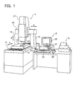
- Fig. 1 is a perspective view illustrative of the entire configuration of an image measuring system according to an embodiment of the invention.
- the system comprises an image measuring machine 1 of the non-contact type, a computer system 2 operative to drive control the image measuring machine 1 and execute required data processing, and a printer 3 operative to print out measurement results.
- the image measuring machine 1 includes a holder 11 on which a measurement stage 13 is equipped to receive a work 12 mounted thereon.
- the measurement stage 13 is driven in the Y-axis direction by a Y-axis drive mechanism, not shown.
- a Y-axis drive mechanism At the central portion between both side edges of the holder 11 are fixed support arms 14, 15 extending upward.
- An X-axis guide 16 is fixed to link both upper ends of the support arms 14, 15.
- the X-axis guide 16 supports an imaging unit 17 thereon.
- the imaging unit 17 is driven along the X-axis guide 16 by an X-axis drive mechanism, not shown.
- the imaging unit 17 has a lower end portion equipped with a CCD camera 18 as opposing the measurement stage 13.
- the imaging unit 17 contains an illuminator and a focusing mechanism as well as a Z-axis drive mechanism, not shown, operative to move the position of the CCD camera 18 in the Z-axis.
- the computer system 2 comprises a computer body 21, a keyboard 22, a joystick box (hereinafter referred to as J/S) 23, a mouse 24 and a CRT 25.
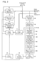
- the computer body 21 may realize functions shown in Fig. 2 together with certain programs stored inside.
- stage movement processor 31 operative to control the image measuring machine 1 based on instruction inputs from input means such as the keyboard 22, the J/S 23 and the mouse 24; an illumination adjuster 32; and an other measurement condition adjuster 33.
- the stage movement processor 31 controls an XYZ axes drive mechanism for the image measuring machine 1 to move the position of the CCD camera 18 relative to the measurement stage 13.
- the illumination adjuster 32 drives the illuminator for the image measuring machine 1 to emit strobe light continuously at a certain period and adjusts the pulse width of the strobe light based on an illumination adjusting instruction input.
- the other measurement condition adjuster 33 In a nonstop measurement mode, it drives the illuminator to emit strobe light with a preset pulse width at designated measurement locations. Based on other measurement condition adjusting instruction inputs, the other measurement condition adjuster 33 adjusts other measurement conditions such as lens power and focusing adjustment.
- the stage position, the pulse width of strobe light and the other measurement condition information adjusted at the processors 31-33 are taken in by a parameter acquire 34 based on certain instruction inputs from the input means.
- the parameter taken in by the parameter acquire 34 is stored in a parameter storage unit 35.
- Apart program generator 36 generates a part program for measurement using the parameter stored in the parameter storage unit 35.
- the generated part program is stored in a part program storage unit 37.
- the part program generator 36 mainly includes a movement direction calculator 361, a synthesized direction calculator 362, a fore/aft-running point calculator 363, a way point calculator 364, and a measurement path setter 365.
- the movement direction calculator 361 is configured to acquire measurement points from the parameters taken from the parameter storage unit 35 to calculate a shortest measurement path that minimizes the distance between two of the measurement points, and a movement direction on the shortest measurement path.
- the synthesized direction calculator 362 is configured to calculate a synthesized direction resulted from synthesis of the movement direction to a certain measurement point from a measurement point located one point anterior and the movement direction from the certain measurement point to a measurement point located one point posterior.
- the synthesis of the two movement directions before and after the measurement point may be other than 1:1 and appropriately modifiable.
- the fore/aft-running point calculator 363 calculates a forerunning point at a position spaced a certain distance backward in the synthesized direction from the measurement point and an aft-running point at a position spaced a certain distance forward in the synthesized direction from the measurement point from which the synthesized direction is calculated.
- the distance from the forerunning point to the measurement point is made longer than the distance from measurement point to the aft-running point.
- the way point calculator 364 is configured to calculate way points arranged along a line containing almost arcs smoothly coupling both the aft-running point related to the above-described measurement point and the forerunning point related to a measurement point located one point posterior in a measurement sequence to the measurement point. The distance between adjacent way points is calculated shorter than the distance from the forerunning point to the measurement point.
- the measurement path setter 365 sets a measurement path along lines connecting the above-described measurement points, forerunning points, aft-running points and way points along synthesized vectors.
- a part program executor 38 reads a required part program out of the part program storage unit 37 and executes it.
- the part program executor appropriately drives the stage movement processor 31, the illumination adjuster 32, theothermeasurement condition adjuster 33 and an image acquirer 43 in accordance with various commands described in the part program.
- the image information captured by the CCD camera 18 is sequentially stored in an image storage unit 41.
- the image information stored in the image storage unit 41 is sequentially displayed on a display unit 25 and captured as still images at the image acquirer 42 based on the part program.
- An image processor 43 executes image processing for image measurement, such as measuring tool setting, edge detection, and coordinate detection to the image information acquired at the image acquirer 42.
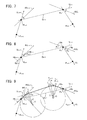
- Figs. 4-9 are schematic views representative of a method of determining measurement points.
- Figs. 6-9 are schematic views representative of amethodof determining a measurement path from a measurement point P n to a measurement point P n+1 .
- Fig. 6 is an enlarged view of a portion A in Fig. 5.
- the parameter acquirer 34 acquires parameters to determine measurement points P 1 -P m (step S1).
- the parameters include information that can specify the measurement points. In addition to the measurement points, they may include information about measurement routes at measurement locations.
- the movement direction calculator 361 calculates a shortest measurement path that minimizes the sum of distances between two of measurement points P 1 -P m , and movement directions V 1 -V m-1 on the measurement paths (step S2).
- the synthesized direction calculator 362 calculates a synthesized direction RV n based on a movement direction V n-1 to a measurement point P n from a measurement point P n-1 located one point anterior on the measurement path and a movement direction from the measurement point P n to the next measurement point P n+1 (step S3).
- the example of measurement shown in Fig. 7 shows the case where the synthesized direction RV n-1 , the movement direction V n-1 and the synthesized direction RV n are determined in this order, and the directional variations occur in the same direction. In this case, there is a sufficient interval D n-1 between the measurement point P n and the measurement point P n-1 .
- two movement directions are synthesized at a proportion of 1:1, which though may be modifiable based on the measurement speed and the angle between measurement points.
- the synthesized directions RV n , RV n-1 are described. Such the synthesized directions are calculated over all measurement points P 2 -P m-1 except for measurement points at a measurement startingpoint (first) and a measurement terminating point (m-th).
- the movement direction V 1 may be regarded as a synthesized direction RV 1 .
- the movement direction V m-1 may be regarded as a synthesized direction RV m .
- the fore/aft-running point calculator 363 calculates an aft-running point Hf n at a position spaced a certain distance F n forward in the synthesized direction RV n from the measurement point P n and a forerunning point Hb n at a position spaced a certain distance B n backward in the synthesized direction RV n from the measurement point P n (step S4).
- the way point calculator 364 determines way points T nl -T nn arranged on a measurement path having both ends on the forerunning point Hb n related to the measurement point P n and the aft-running point Hf n-1 related to a measurement point P n-1 located one point anterior and containing arcs smoothly coupled to these points (step S5).
- the way points T nl -T nn on the measurement path can be determined from a directional variation angle ⁇ and a way point interval L. In this measurement example, way points are calculated to form two arcs.
- the process in the step S5 is not executed and the flow jumps to the step S6.
- the directional variation angle ⁇ is an angular difference between segments that connect a certain position O to way points.
- the way point interval L is a distance between adjacent way points.
- the directional variation angle ⁇ and the way point interval L may be determined arbitrarily on algorithm. A practical measurement, though, requires a threshold to be set in accordance with, for example, the moving speed of the imaging device.
- the directional variation angle may be set to have a threshold ⁇ c of 10° or less, and the way point interval a threshold L c of 0.2 mm or more.
- the threshold L c of the way point interval may be regarded almost as a function of the moving speed of the measuring machine.
- the threshold ⁇ c of the directional variation angle may be regarded as a function of the controllable maximum acceleration performance of the measuring machine.
- (L c , ⁇ c ) may be regarded as a function of the moving speed and can be set per measuring machine type.
- the way point calculator 364 determines whether or not a measurement point P n+2 located two points posterior to the measurement point P n exists (step S6). If the measurement point P n+2 exists (step S6, YES), the subject is transferred from the measurement point P n to a measurement point P n+1 located one point posterior (step S7) and the processes from the step S3-S6 are repeatedly executed.
- a final process is executed (step S8) and the control terminates the flow.
- the final process is a process in which the measurement path setter 365 sets a measurement path along the synthesized directions RV 1 -RV m and through the measurement points P 1 -P m and the way points T 11 -T mn .
- the imaging device moves along a straight line within a certain distance before and after a measurement point and, after passing the certain distance from the measurement point, moves describing an almost arc to smoothly vary the movement direction. Therefore, the imaging device moves linearly before and after a measurement point and accordingly receives no vibration-causing extra load imposed thereon, resulting in a high-precision measurement. After passing the certain distance from the measurement point, the imaging device moves toward the next measurement point describing an almost arc to smoothly vary the movement direction. Accordingly, no load is imposed on the imaging device due to a sharp angular displacement and the moving speed can be maintained constant. Thus, it is possible to execute a measurement much faster.
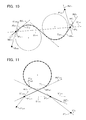
- Figs. 10-12 an example of setting a measurement path is described, which is different from the example of arranging measurement points shown in Figs. 6-9.
- Figs. 10-12 shows an example of setting measurement paths.
- way points along arcs on these measurement paths are calculated at the way point calculator 364. They may be determined on the basis of the moving speed of the imaging device, the distance between measurement points, and the angular difference between movement directions at two measurement points for use in calculation of way points.
- the variation direction from RV' n-1 to V' n-1 is opposite to the variation direction from V' n-1 to RV' n , and a common tangent line sandwiched between two arcs exists.
- the way point calculator 364 may arrange way points T' n1 -T' nn along two arcs and forms a path that connects between the two arcs along a straight line.
- the synthesized direction RV" n-1 , the movement direction V" n-1 , and the synthesized direction RV" n in this order have same variation directions, and a common tangent line between two arcs can not become a path.
- the measurement point P" n and the measurement point P" n-1 have a distance D" n-1 therebetween, and the distance D" n-1 is shorter than the distance D n-1 .
- the way point calculator 364 arranges way points T" n1 -T" nn along one arc that commonly contacts straight lines RV" n-1 and RV" n .
- the example shown in Fig. 12 is different from the example shown in Fig. 10 in distance D" ' n-1 between a measurement point P" ' n and a measurement point P" ' n-1 and the distance D" ' n-1 is shorter than the distance D' n-1 .
- the way point calculator 364 calculates a common tangent line against two circles: a circle that is the circle generated through the above-described method and shifted to a line-symmetrical position about RV" ' n-1 ; and a circle on the P" ' n side. It then arranges way points T" ' n1 -T" ' nn along arcs located on a path including these circles and the common tangent line.
- the way point calculator 364 optimizes the arrangement of the arcs and straight line along which way points are arranged. Accordingly, any measurement path (arrangement of way points) imposes no load on the imaging device due to a sharp angular displacement. In addition, the moving speed can be maintained constant. Therefore, it is possible to execute a measurement much faster.
Landscapes
- Physics & Mathematics (AREA)
- General Physics & Mathematics (AREA)
- Length Measuring Devices By Optical Means (AREA)
- Image Input (AREA)
Abstract
Description
- This application is based on and claims the benefit of priority from the prior
Japanese Patent Application No. 2006-51774, filed on February 28, 2006 - The present invention relates to an image measuring system, image measuring method and image measuring program provided with a nonstop measurement mode for moving an imaging means relative to a measurement stage that supports an object to be measured and taking in instantaneous image information without making a stop at a designated measurement location.
- A conventional CNC image measuring machine moves a measurement stage relative to an imaging means such as a CCD camera, as shown in Fig. 13, and makes a stop at a measurement location. Then, it adjusts the amount of illuminative light to acquire image information about an object to be measured, and applies image processing such as measuring tool setting and edge detection to the acquired image information, thereby executing a measurement at one measurement location. This measurement is repeatedly executed as
Measurement 1,Measurement 2, ... at all measurement locations to complete measurements at required locations (hereinafter such the measurement mode is referred to as a "standard mode"). - In contrast, for the purpose of improving the measurement throughput, an image measuring machine is proposed, which has a measurement mode for measuring without making no stop of the measurement stage relative to the imaging means even at the measurement location (hereinafter such the measurement mode is referred to as a "nonstop measurement mode") (
JP 2004-535587A - The above-described conventional image measuring machine has no problem if the measurement locations are arranged along a straight line. To the contrary, if they are not arranged along a straight line, when the speed of the measuring machine is kept constant to execute measurements at measurement locations, a problem may arise. Namely, a larger variation angle of the advancing direction, with a measurement pulse such as a square (a directional variation angle of 90º) or a Z-shape (a directional variation angle of 90º or more) , requires an addition of a larger acceleration to follow a turning location (hereinafter referred to as a bent point) and accordingly overloads the machine. This results in vibrations of the machine and causes shakes of subsequent captured images (deterioration of the image quality) and shakes of imaging positions, which deteriorate measurement accuracy of the image. In some cases, the overload may blow a protective fuse.
- The present invention has been made in consideration of such the problem and has an object to provide an image measuring system, image measuring method and image measuring program capable of preventing deterioration of measurement accuracy and of imposing no overload on any movement mechanism.
- The present invention provides an image measuring system for moving an imaging means relative to a measurement stage that supports an object to be measured and taking in instantaneous image information about the object without making a stop of the imaging means at any of a plurality of measurement locations, thereby performing image measuring. The system comprises a measurement point acquirer operative to acquire measurement points; a movement direction calculator operative to acquire a shortest path connecting between the measurement points and to calculate a movement direction on the shortest path; a synthesized direction calculator operative to calculate a synthesized direction resulted from synthesis of movement directions before and after the measurement point; a fore/aft-running point calculator operative to calculate a forerunning point at a position spaced a certain distance backward in the synthesized direction from the measurement point from which the synthesized direction is calculated and to calculate an aft-running point at a position spaced a certain distance forward in the synthesized direction from the measurement point from which the synthesized direction is calculated; a way point calculator operative to calculate a plurality of way points arranged on a path smoothly connecting the aft-running point to the forerunning point related to a measurement point located one point posterior in a measurement sequence to the measurement point from which the aft-running point is calculated, such that the path follows the synthesized direction at both points; and a measurement path setter operative to set a measurement path following the synthesized directions and passing through the calculated way points and the measurement points.
- The present invention also provides an image measuring method for moving an imaging means relative to a measurement stage that supports an object to be measured and taking in instantaneous image information about the object without making a stop of the imaging means at any of a plurality of measurement locations, thereby performing image measuring. The method comprises a measurement point acquisition step of acquiring measurement points; a movement direction calculation step of acquiring a shortest path connecting between the measurement points and calculating a movement direction on the shortest path; a synthesized direction calculation step of calculating a synthesized direction resulted from synthesis of movement directions before and after the measurement point; a fore/aft-running point calculation step of calculating a forerunning point at a position spaced a certain distance backward in the synthesized direction from the measurement point from which the synthesized direction is calculated and calculating an aft-running point at a position spaced a certain distance forward in the synthesized direction from the measurement point from which the synthesized direction is calculated; a way point calculation step of calculating a plurality of way points arranged on a path smoothly connecting the aft-running point to the forerunning point related to a measurement point located one point posterior in a measurement sequence to the measurement point from which the aft-running point is calculated, such that the path follows the synthesized direction at both points; and a measurement path setting step of setting a measurement path following the synthesized directions and passing through the calculated way points and the measurement points.
- The present invention further provides a computer executable, image measuring program for moving an imaging means relative to a measurement stage that supports an object to be measured and taking in instantaneous image information about the object without making a stop of the imaging means at any of a plurality of measurement locations , thereby performing image measuring. The program comprises a measurement point acquisition step of acquiring measurement points; a movement direction calculation step of acquiring a shortest path connecting between the measurement points and calculating a movement direction on the shortest path; a synthesized direction calculation step of calculating a synthesized direction resulted from synthesis of movement directions before and after the measurement point; a fore/aft-running point calculation step of calculating a forerunning point at a position spaced a certain distance backward in the synthesized direction from the measurement point from which the synthesized direction is calculated and calculating an aft-running point at a position spaced a certain distance forward in the synthesized direction from the measurement point from which the synthesized direction is calculated; a way point calculation step of calculating a plurality of way points arranged on a path smoothly connecting the aft-running point to the forerunning point related to a measurement point located one point posterior in a measurement sequence to the measurement point from which the aft-running point is calculated, such that the path follows the synthesized direction at both points; and a measurement path setting step of setting a measurement path following the synthesized directions and passing through the calculated way points and the measurement points.
-
- Fig. 1 is an external perspective view illustrative of a configuration of an image measuring system according to an embodiment of the invention.
- Fig. 2 is a functional block diagram of a computer in the measuring system.
- Fig. 3 is a flowchart illustrative of a procedure of setting measurement paths in the measuring system.
- Fig. 4 shows part of the measurement in the system.
- Fig. 5 shows part of the measurement in the system.
- Fig. 6 shows part of the measurement in the system.
- Fig. 7 shows part of the measurement in the system.
- Fig. 8 shows part of the measurement in the system.
- Fig. 9 shows part of the measurement in the system.
- Fig. 10 shows an example of setting measurement paths in the system.
- Fig. 11 shows an example of setting measurement paths in the system.
- Fig. 12 shows an example of setting measurement paths in the system.
- Fig. 13 illustrates a measurement in a standard stop mode.
- Fig. 14 illustrates a measurement in a nonstop measurement mode.
- The embodiment of the present invention will now be described below with reference to the drawings.
- Fig. 1 is a perspective view illustrative of the entire configuration of an image measuring system according to an embodiment of the invention. The system comprises an
image measuring machine 1 of the non-contact type, acomputer system 2 operative to drive control theimage measuring machine 1 and execute required data processing, and aprinter 3 operative to print out measurement results. - The
image measuring machine 1 includes aholder 11 on which ameasurement stage 13 is equipped to receive awork 12 mounted thereon. Themeasurement stage 13 is driven in the Y-axis direction by a Y-axis drive mechanism, not shown. At the central portion between both side edges of theholder 11 are fixedsupport arms X-axis guide 16 is fixed to link both upper ends of thesupport arms guide 16 supports animaging unit 17 thereon. Theimaging unit 17 is driven along theX-axis guide 16 by an X-axis drive mechanism, not shown. Theimaging unit 17 has a lower end portion equipped with aCCD camera 18 as opposing themeasurement stage 13. Theimaging unit 17 contains an illuminator and a focusing mechanism as well as a Z-axis drive mechanism, not shown, operative to move the position of theCCD camera 18 in the Z-axis. - The
computer system 2 comprises acomputer body 21, akeyboard 22, a joystick box (hereinafter referred to as J/S) 23, amouse 24 and a CRT 25. Thecomputer body 21 may realize functions shown in Fig. 2 together with certain programs stored inside. - It includes a
stage movement processor 31 operative to control theimage measuring machine 1 based on instruction inputs from input means such as thekeyboard 22, the J/S 23 and themouse 24; anillumination adjuster 32; and an other measurement condition adjuster 33. Based on a stage movement instruction input from the input means, thestage movement processor 31 controls an XYZ axes drive mechanism for theimage measuring machine 1 to move the position of theCCD camera 18 relative to themeasurement stage 13. The illumination adjuster 32, on teaching, drives the illuminator for theimage measuring machine 1 to emit strobe light continuously at a certain period and adjusts the pulse width of the strobe light based on an illumination adjusting instruction input. In a nonstop measurement mode, it drives the illuminator to emit strobe light with a preset pulse width at designated measurement locations. Based on other measurement condition adjusting instruction inputs, the other measurement condition adjuster 33 adjusts other measurement conditions such as lens power and focusing adjustment. - The stage position, the pulse width of strobe light and the other measurement condition information adjusted at the processors 31-33 are taken in by a parameter acquire 34 based on certain instruction inputs from the input means. The parameter taken in by the parameter acquire 34 is stored in a
parameter storage unit 35.Apart program generator 36 generates a part program for measurement using the parameter stored in theparameter storage unit 35. The generated part program is stored in a partprogram storage unit 37. - The
part program generator 36 mainly includes amovement direction calculator 361, a synthesizeddirection calculator 362, a fore/aft-runningpoint calculator 363, away point calculator 364, and ameasurement path setter 365. - The
movement direction calculator 361 is configured to acquire measurement points from the parameters taken from theparameter storage unit 35 to calculate a shortest measurement path that minimizes the distance between two of the measurement points, and a movement direction on the shortest measurement path. - The
synthesized direction calculator 362 is configured to calculate a synthesized direction resulted from synthesis of the movement direction to a certain measurement point from a measurement point located one point anterior and the movement direction from the certain measurement point to a measurement point located one point posterior. The synthesis of the two movement directions before and after the measurement point may be other than 1:1 and appropriately modifiable. - The fore/aft-running
point calculator 363 calculates a forerunning point at a position spaced a certain distance backward in the synthesized direction from the measurement point and an aft-running point at a position spaced a certain distance forward in the synthesized direction from the measurement point from which the synthesized direction is calculated. The distance from the forerunning point to the measurement point is made longer than the distance from measurement point to the aft-running point. - The
way point calculator 364 is configured to calculate way points arranged along a line containing almost arcs smoothly coupling both the aft-running point related to the above-described measurement point and the forerunning point related to a measurement point located one point posterior in a measurement sequence to the measurement point. The distance between adjacent way points is calculated shorter than the distance from the forerunning point to the measurement point. - The
measurement path setter 365 sets a measurement path along lines connecting the above-described measurement points, forerunning points, aft-running points and way points along synthesized vectors. - A
part program executor 38 reads a required part program out of the partprogram storage unit 37 and executes it. The part program executor appropriately drives thestage movement processor 31, theillumination adjuster 32,theothermeasurement condition adjuster 33 and animage acquirer 43 in accordance with various commands described in the part program. The image information captured by theCCD camera 18 is sequentially stored in animage storage unit 41. The image information stored in theimage storage unit 41 is sequentially displayed on adisplay unit 25 and captured as still images at theimage acquirer 42 based on the part program. Animage processor 43 executes image processing for image measurement, such as measuring tool setting, edge detection, and coordinate detection to the image information acquired at theimage acquirer 42. - With reference to a flowchart of Fig. 3 and appropriately to Figs. 4-9, a procedure of setting measurement paths in the image measuring system thus configured according to the embodiment is described. The measurement path setting may be processed during generation of the part program in offline teaching. Figs. 4-9 are schematic views representative of a method of determining measurement points. In particular, Figs. 6-9 are schematic views representative of amethodof determining a measurement path from a measurement point Pn to a measurement point Pn+1. Fig. 6 is an enlarged view of a portion A in Fig. 5.
- First, as shown in Fig. 4, the
parameter acquirer 34 acquires parameters to determine measurement points P1-Pm (step S1). The parameters include information that can specify the measurement points. In addition to the measurement points, they may include information about measurement routes at measurement locations. - Next, as shown in Figs. 5 and 6, the
movement direction calculator 361 calculates a shortest measurement path that minimizes the sum of distances between two of measurement points P1-Pm, and movement directions V1-Vm-1 on the measurement paths (step S2). - Subsequently, as shown in Fig. 7, the
synthesized direction calculator 362 calculates a synthesized direction RVn based on a movement direction Vn-1 to a measurement point Pn from a measurement point Pn-1 located one point anterior on the measurement path and a movement direction from the measurement point Pn to the next measurement point Pn+1 (step S3). The example of measurement shown in Fig. 7 shows the case where the synthesized direction RVn-1, the movement direction Vn-1 and the synthesized direction RVn are determined in this order, and the directional variations occur in the same direction. In this case, there is a sufficient interval Dn-1 between the measurement point Pn and the measurement point Pn-1. In Fig. 7, two movement directions are synthesized at a proportion of 1:1, which though may be modifiable based on the measurement speed and the angle between measurement points. - In Figs. 7-9, for simplification of the description, only the synthesized directions RVn, RVn-1 are described. Such the synthesized directions are calculated over all measurement points P2-Pm-1 except for measurement points at a measurement startingpoint (first) and a measurement terminating point (m-th). As for the measurement point P1 from which the measurement starts, the movement direction V1 may be regarded as a synthesized direction RV1. As for the measurement point Pm at which the measurement terminates, the movement direction Vm-1 may be regarded as a synthesized direction RVm.
- Next, as shown in Fig. 8, the fore/aft-running
point calculator 363 calculates an aft-running point Hfn at a position spaced a certain distance Fn forward in the synthesized direction RVn from the measurement point Pn and a forerunning point Hbn at a position spaced a certain distance Bn backward in the synthesized direction RVn from the measurement point Pn (step S4). - Subsequently, as shown in Fig. 9, the
way point calculator 364 determines way points Tnl-Tnn arranged on a measurement path having both ends on the forerunning point Hbn related to the measurement point Pn and the aft-running point Hfn-1 related to a measurement point Pn-1 located one point anterior and containing arcs smoothly coupled to these points (step S5). The way points Tnl-Tnn on the measurement path can be determined from a directional variation angle θ and a way point interval L. In this measurement example, way points are calculated to form two arcs. At the measurement starting point from which the measurement starts, the process in the step S5 is not executed and the flow jumps to the step S6. - The directional variation angle θ is an angular difference between segments that connect a certain position O to way points. The way point interval L is a distance between adjacent way points. The directional variation angle θ and the way point interval L may be determined arbitrarily on algorithm. A practical measurement, though, requires a threshold to be set in accordance with, for example, the moving speed of the imaging device. For example, the directional variation angle may be set to have a threshold θc of 10° or less, and the way point interval a threshold Lc of 0.2 mm or more. The threshold Lc of the way point interval may be regarded almost as a function of the moving speed of the measuring machine. The threshold θc of the directional variation angle may be regarded as a function of the controllable maximum acceleration performance of the measuring machine. In a word, (Lc, θc) may be regarded as a function of the moving speed and can be set per measuring machine type.
- The
way point calculator 364 determines whether or not a measurement point Pn+2 located two points posterior to the measurement point Pn exists (step S6). If the measurement point Pn+2 exists (step S6, YES), the subject is transferred from the measurement point Pn to a measurement point Pn+1 located one point posterior (step S7) and the processes from the step S3-S6 are repeatedly executed. - If no measurement point Pn+2 exists (step S6, No), a final process is executed (step S8) and the control terminates the flow. The final process is a process in which the
measurement path setter 365 sets a measurement path along the synthesized directions RV1-RVm and through the measurement points P1-Pm and the way points T11-Tmn. - Thus, in this embodiment, the imaging device moves along a straight line within a certain distance before and after a measurement point and, after passing the certain distance from the measurement point, moves describing an almost arc to smoothly vary the movement direction. Therefore, the imaging device moves linearly before and after a measurement point and accordingly receives no vibration-causing extra load imposed thereon, resulting in a high-precision measurement. After passing the certain distance from the measurement point, the imaging device moves toward the next measurement point describing an almost arc to smoothly vary the movement direction. Accordingly, no load is imposed on the imaging device due to a sharp angular displacement and the moving speed can be maintained constant. Thus, it is possible to execute a measurement much faster.
- Referring now to Figs. 10-12, an example of setting a measurement path is described, which is different from the example of arranging measurement points shown in Figs. 6-9. Figs. 10-12 shows an example of setting measurement paths. As described above, way points along arcs on these measurement paths are calculated at the
way point calculator 364. They may be determined on the basis of the moving speed of the imaging device, the distance between measurement points, and the angular difference between movement directions at two measurement points for use in calculation of way points. - In the example shown in Fig. 10, the variation direction from RV'n-1 to V'n-1 is opposite to the variation direction from V'n-1 to RV'n, and a common tangent line sandwiched between two arcs exists. In such the case, the
way point calculator 364 may arrange way points T'n1-T'nn along two arcs and forms a path that connects between the two arcs along a straight line. - In the example shown in Fig. 11, the synthesized direction RV"n-1, the movement direction V"n-1, and the synthesized direction RV"n in this order have same variation directions, and a common tangent line between two arcs can not become a path. Different from the example shown in Fig. 9, the measurement point P"n and the measurement point P"n-1 have a distance D"n-1 therebetween, and the distance D"n-1 is shorter than the distance Dn-1. In such the case, it is impossible for two arcs and a straight line that connects between the arcs to configure a path as shown in Fig. 9. Therefore, the
way point calculator 364 arranges way points T"n1-T"nn along one arc that commonly contacts straight lines RV"n-1 and RV"n. - The example shown in Fig. 12 is different from the example shown in Fig. 10 in distance D" 'n-1 between a measurement point P" 'n and a measurement point P" ' n-1 and the distance D" 'n-1 is shorter than the distance D'n-1. In such the case, the
way point calculator 364 calculates a common tangent line against two circles: a circle that is the circle generated through the above-described method and shifted to a line-symmetrical position about RV" 'n-1; and a circle on the P" 'n side. It then arranges way points T" 'n1 -T" 'nn along arcs located on a path including these circles and the common tangent line. - Thus, in accordance with arrangement patterns of measurement points (such as distances between measurement points and movement directions), the
way point calculator 364 optimizes the arrangement of the arcs and straight line along which way points are arranged. Accordingly, any measurement path (arrangement of way points) imposes no load on the imaging device due to a sharp angular displacement. In addition, the moving speed can be maintained constant. Therefore, it is possible to execute a measurement much faster.
Claims (12)
- An image measuring system for moving an imaging means (18) relative to a measurement stage (13) that supports an object to be measured and taking in instantaneous image information about the object without making a stop of the imaging means (18) at any of a plurality of measurement locations, thereby performing image measuring, the system comprising:a measurement point acquirer (34) operative to acquire measurement points;amovement direction calculator (361) operative to acquire a shortest path connecting between the measurement points and to calculate a movement direction on the shortest path;a synthesized direction calculator (362) operative to calculate a synthesized direction resulted from synthesis of movement directions before and after the measurement point;a fore/aft-running point calculator (363) operative to calculate a forerunning point at a position spaced a certain distance backward in the synthesized direction from the measurement point from which the synthesized direction is calculated and to calculate an aft-running point at a position spaced a certain distance forward in the synthesized direction from the measurement point from which the synthesized direction is calculated;a way point calculator (364) operative to calculate a plurality of way points arranged on a path smoothly connecting the aft-running point to the forerunning point related to a measurement point located one point posterior in a measurement sequence to the measurement point from which the aft-running point is calculated, such that the path follows the synthesized direction at both points; anda measurement path setter (365) operative to set a measurement path following the synthesized directions and passing through the calculated way points and the measurement points.
- The image measuring system according to claim 1, wherein the distance between adjacent way points and the angular difference between adjacent way points about a cardinal point at a certain position are determined in relation to the distance between adjacent measurement points and the moving speed of the imaging means (18).
- The image measuring system according to claim 1, wherein the measurement point and the forerunning point have a distance longer than the distance between the measurement point and the aft-running point.
- The image measuring system according to claim 1, wherein the path containing the way points is shaped arc.
- An image measuring method for moving an imaging means (18) relative to a measurement stage (13) that supports an object to be measured and taking in instantaneous image information about the object without making a stop of the imaging means (18) at any of a plurality of measurement locations, thereby performing image measuring, the method comprising:a measurement point acquisition step of acquiring measurement points;a movement direction calculation step of acquiring a shortest path connecting between the measurement points and calculating a movement direction on the shortest path;a synthesized direction calculation step of calculating a synthesized direction resulted from synthesis of movement directions before and after the measurement point;a fore/aft-running point calculation step of calculating a forerunning point at a position spaced a certain distance backward in the synthesized direction from the measurement point from which the synthesized direction is calculated and calculating an aft-running point at a position spaced a certain distance forward in the synthesized direction from the measurement point from which the synthesized direction is calculated;a way point calculation step of calculating a plurality of way points arranged on a path smoothly connecting the aft-running point to the forerunning point related to a measurement point located one point posterior in a measurement sequence to the measurement point from which the aft-running point is calculated, such that the path follows the synthesized direction at both points; anda measurement path setting step of setting a measurement path following the synthesized directions and passing through the calculated way points and the measurement points.
- The image measuring method according to claim 5, wherein the distance between adjacent way points and the angular difference between adjacent way points about a cardinal point at a certain position are determined in relation to the distance between adjacent measurement points and the moving speed of the imaging means (18).
- The image measuring method according to claim 5, wherein the measurement point and the forerunning point have a distance longer than the distance between the measurement point and the aft-running point.
- The image measuring method according to claim 5, wherein the path containing the way points is shaped arc.
- A computer executable, image measuring program for moving an imaging means (18) relative to a measurement stage (13) that supports an object to be measured and taking in instantaneous image information about the object without making a stop of the imaging means (18) at any of a plurality of measurement locations, thereby performing image measuring, the program comprising:a measurement point acquisition step of acquiring measurement points;a movement direction calculation step of acquiring a shortest path connecting between the measurement points and calculating a movement direction on the shortest path;a synthesized direction calculation step of calculating a synthesized direction resulted from synthesis of movement directions before and after the measurement point;a fore/aft-running point calculation step of calculating a forerunning point at a position spaced a certain distance backward in the synthesized direction from the measurement point from which the synthesized direction is calculated and calculating an aft-running point at a position spaced a certain distance forward in the synthesized direction from the measurement point from which the synthesized direction is calculated;a way point calculation step of calculating a plurality of way points arranged on a path smoothly connecting the aft-running point to the forerunning point related to a measurement point located one point posterior in a measurement sequence to the measurement point from which the aft-running point is calculated, such that the path follows the synthesized direction at both points; anda measurement path setting step of setting a measurement path following the synthesized directions and passing through the calculated way points and the measurement points.
- The image measuring program according to claim 9, wherein the distance between adjacent way points and the angular difference between adjacent way points about a cardinal point at a certain position are determined in relation to the distance between adjacent measurement points and the moving speed of the imaging means (18).
- The image measuring program according to claim 9, wherein the measurement point and the forerunning point have a distance longer than the distance between the measurement point and the aft-running point.
- The image measuring program according to claim 9, wherein the path containing the way points is shaped arc.
Applications Claiming Priority (1)
| Application Number | Priority Date | Filing Date | Title |
|---|---|---|---|
| JP2006051774A JP4652252B2 (en) | 2006-02-28 | 2006-02-28 | Image measurement system, image measurement method, and image measurement program |
Publications (2)
| Publication Number | Publication Date |
|---|---|
| EP1826528A1 true EP1826528A1 (en) | 2007-08-29 |
| EP1826528B1 EP1826528B1 (en) | 2008-09-10 |
Family
ID=37905639
Family Applications (1)
| Application Number | Title | Priority Date | Filing Date |
|---|---|---|---|
| EP07004014A Active EP1826528B1 (en) | 2006-02-28 | 2007-02-27 | Image measuring system, image measuring method and image measuring program |
Country Status (4)
| Country | Link |
|---|---|
| US (1) | US7822230B2 (en) |
| EP (1) | EP1826528B1 (en) |
| JP (1) | JP4652252B2 (en) |
| DE (1) | DE602007000113D1 (en) |
Families Citing this family (10)
| Publication number | Priority date | Publication date | Assignee | Title |
|---|---|---|---|---|
| JP4833588B2 (en) * | 2005-06-03 | 2011-12-07 | 株式会社ミツトヨ | Image measurement system and non-stop image measurement program creation method and execution method |
| US8530243B2 (en) * | 2009-04-20 | 2013-09-10 | Bio-Rad Laboratories Inc. | Non-scanning SPR system |
| CN102200427A (en) * | 2010-03-22 | 2011-09-28 | 鸿富锦精密工业(深圳)有限公司 | Image measuring machine |
| JP5936330B2 (en) * | 2011-11-04 | 2016-06-22 | キヤノン株式会社 | Acoustic wave measuring device and control method of acoustic wave measuring device |
| JP5836760B2 (en) * | 2011-11-04 | 2015-12-24 | キヤノン株式会社 | Acoustic wave acquisition apparatus and acoustic wave acquisition method |
| CN102538671B (en) * | 2011-11-25 | 2013-12-18 | 中南大学 | Oscillation center measuring method based on machine vision plane oscillation |
| CN103673872A (en) * | 2012-09-10 | 2014-03-26 | 中国科学院空间科学与应用研究中心 | Measurement method and measurement system of liquid drop volume |
| WO2014205632A1 (en) * | 2013-06-24 | 2014-12-31 | Adobe Systems Incorporated | Gravity point drawing method |
| CN103743347B (en) * | 2014-01-10 | 2016-04-20 | 盐城工学院 | A kind of optical altitude measurement method |
| CN106645203A (en) * | 2017-02-13 | 2017-05-10 | 广州视源电子科技股份有限公司 | Image acquisition method and device |
Citations (4)
| Publication number | Priority date | Publication date | Assignee | Title |
|---|---|---|---|---|
| WO1991020020A1 (en) * | 1990-06-20 | 1991-12-26 | Renishaw Plc | Measurement of a workpiece |
| DE19529547A1 (en) * | 1995-08-11 | 1997-02-13 | Zeiss Carl Fa | Method for controlling coordinate measuring machines |
| EP1102139A2 (en) * | 1999-11-19 | 2001-05-23 | Siemens Energy & Automation, Inc. | Apparatus and method for smooth cornering in a motion control system |
| WO2003009070A2 (en) * | 2001-07-16 | 2003-01-30 | Werth Messtechnik Gmbh | Method for measuring an object by means of a co-ordinate measuring device with an image processing sensor |
Family Cites Families (17)
| Publication number | Priority date | Publication date | Assignee | Title |
|---|---|---|---|---|
| US4623977A (en) * | 1984-09-10 | 1986-11-18 | Allied Corporation | Method and apparatus for linear interpolation |
| US4688182A (en) * | 1984-09-10 | 1987-08-18 | Allied Corporation | Method and apparatus for generating a set of signals representing a curve |
| JPH06507742A (en) * | 1991-05-21 | 1994-09-01 | ケンブリッジ アニメーション システムズ リミテッド | Video creation device |
| JPH06110992A (en) * | 1992-09-25 | 1994-04-22 | Agency Of Ind Science & Technol | Shape deformation input operation method in CAD system |
| JP3234309B2 (en) * | 1992-10-28 | 2001-12-04 | キヤノン株式会社 | Complex system path control method and apparatus |
| US5636338A (en) * | 1993-01-29 | 1997-06-03 | Silicon Graphics, Inc. | Method for designing curved shapes for use by a computer |
| US5500927A (en) * | 1993-03-18 | 1996-03-19 | Macromedia, Inc. | System and method for simplifying a computer-generated path |
| US5594852A (en) * | 1994-08-17 | 1997-01-14 | Laser Products, Inc. | Method for operating a curve forming device |
| US5726896A (en) * | 1995-08-30 | 1998-03-10 | University Of Utah Research Foundation | Method and system for spline interpolation, and their use in CNC |
| US6304677B1 (en) * | 1998-04-07 | 2001-10-16 | Adobe Systems Incorporated | Smoothing and fitting point sequences |
| JP3705923B2 (en) * | 1998-04-09 | 2005-10-12 | 株式会社ソニー・コンピュータエンタテインメント | Image processing apparatus, image processing method, program providing medium, and data providing medium |
| US6256039B1 (en) * | 1998-08-14 | 2001-07-03 | The Board Of The Leland Stanford Junior University | Methods for manipulating curves constrained to unparameterized surfaces |
| CA2345464A1 (en) * | 1998-09-24 | 2000-03-30 | Brigit Ananya | Computer curve construction system and method |
| DE19901934C2 (en) * | 1999-01-19 | 2001-07-19 | Heidelberger Druckmasch Ag | Method for generating a frame for graphic objects which are described by Bezier curves |
| US7420588B2 (en) * | 1999-06-09 | 2008-09-02 | Mitutoyo Corporation | Measuring method, measuring system and storage medium |
| US6757613B2 (en) * | 2001-12-20 | 2004-06-29 | Schlumberger Technology Corporation | Graphical method for designing the trajectory of a well bore |
| US7116327B2 (en) * | 2004-08-31 | 2006-10-03 | A{grave over (g)}fa Corporation | Methods for generating control points for cubic bezier curves |
-
2006
- 2006-02-28 JP JP2006051774A patent/JP4652252B2/en not_active Expired - Lifetime
-
2007
- 2007-02-26 US US11/710,563 patent/US7822230B2/en active Active
- 2007-02-27 DE DE602007000113T patent/DE602007000113D1/en active Active
- 2007-02-27 EP EP07004014A patent/EP1826528B1/en active Active
Patent Citations (4)
| Publication number | Priority date | Publication date | Assignee | Title |
|---|---|---|---|---|
| WO1991020020A1 (en) * | 1990-06-20 | 1991-12-26 | Renishaw Plc | Measurement of a workpiece |
| DE19529547A1 (en) * | 1995-08-11 | 1997-02-13 | Zeiss Carl Fa | Method for controlling coordinate measuring machines |
| EP1102139A2 (en) * | 1999-11-19 | 2001-05-23 | Siemens Energy & Automation, Inc. | Apparatus and method for smooth cornering in a motion control system |
| WO2003009070A2 (en) * | 2001-07-16 | 2003-01-30 | Werth Messtechnik Gmbh | Method for measuring an object by means of a co-ordinate measuring device with an image processing sensor |
Also Published As
| Publication number | Publication date |
|---|---|
| JP4652252B2 (en) | 2011-03-16 |
| DE602007000113D1 (en) | 2008-10-23 |
| US7822230B2 (en) | 2010-10-26 |
| EP1826528B1 (en) | 2008-09-10 |
| US20070201041A1 (en) | 2007-08-30 |
| JP2007233516A (en) | 2007-09-13 |
Similar Documents
| Publication | Publication Date | Title |
|---|---|---|
| EP1826528B1 (en) | Image measuring system, image measuring method and image measuring program | |
| JP5923371B2 (en) | Work transfer system | |
| EP2634530A1 (en) | Shape measuring device, shape measuring method, structure manufacturing method, and program | |
| EP3029930A1 (en) | Vision measuring device and auto-focusing control method | |
| US7728990B2 (en) | Image measuring system and methods of generating and executing non-stop image measuring program | |
| CN116194252B (en) | Robotic system | |
| CN104039511A (en) | Imaging inspection device, and control device and control method therefor | |
| US12134195B2 (en) | Control device for robot, robot system, control method, and program | |
| CN117245225B (en) | Laser marking methods, devices, terminal equipment, and storage media | |
| JP2021088003A (en) | Robot coordinate system alignment method, alignment system, and alignment device | |
| US11559888B2 (en) | Annotation device | |
| JP2023101664A (en) | Optical axis adjusting apparatus | |
| US11667032B2 (en) | Processing device | |
| EP1729086B2 (en) | Image measuring system, image measuring method and image measuring program | |
| JPH11283035A (en) | Focus adjustment device for image equipment | |
| EP1837725A2 (en) | Image measuring machine moving an imaging means in a nonstop measurement mode | |
| JP2018169333A (en) | Body orientation estimation apparatus and body orientation estimation program | |
| EP1729085B1 (en) | Image measuring method, image measuring system and image measuring program | |
| WO2020071167A1 (en) | Optical axis adjustment apparatus | |
| JP2001041711A (en) | Method and apparatus for correcting table deflection of image measuring machine | |
| JP3144873U (en) | Image measuring device | |
| US20250387908A1 (en) | Robot control device | |
| JP4638077B2 (en) | Scanning wide area shape analyzer for test surface | |
| US20170094200A1 (en) | Image processing apparatus and positioning system | |
| JP2559646B2 (en) | Image processing method in optical measuring device |
Legal Events
| Date | Code | Title | Description |
|---|---|---|---|
| PUAI | Public reference made under article 153(3) epc to a published international application that has entered the european phase |
Free format text: ORIGINAL CODE: 0009012 |
|
| AK | Designated contracting states |
Kind code of ref document: A1 Designated state(s): AT BE BG CH CY CZ DE DK EE ES FI FR GB GR HU IE IS IT LI LT LU LV MC NL PL PT RO SE SI SK TR |
|
| AX | Request for extension of the european patent |
Extension state: AL BA HR MK YU |
|
| 17P | Request for examination filed |
Effective date: 20071207 |
|
| AKX | Designation fees paid |
Designated state(s): DE FR GB |
|
| GRAP | Despatch of communication of intention to grant a patent |
Free format text: ORIGINAL CODE: EPIDOSNIGR1 |
|
| GRAS | Grant fee paid |
Free format text: ORIGINAL CODE: EPIDOSNIGR3 |
|
| GRAA | (expected) grant |
Free format text: ORIGINAL CODE: 0009210 |
|
| AK | Designated contracting states |
Kind code of ref document: B1 Designated state(s): DE FR GB |
|
| REG | Reference to a national code |
Ref country code: GB Ref legal event code: FG4D |
|
| REF | Corresponds to: |
Ref document number: 602007000113 Country of ref document: DE Date of ref document: 20081023 Kind code of ref document: P |
|
| PLBE | No opposition filed within time limit |
Free format text: ORIGINAL CODE: 0009261 |
|
| STAA | Information on the status of an ep patent application or granted ep patent |
Free format text: STATUS: NO OPPOSITION FILED WITHIN TIME LIMIT |
|
| 26N | No opposition filed |
Effective date: 20090611 |
|
| REG | Reference to a national code |
Ref country code: FR Ref legal event code: PLFP Year of fee payment: 10 |
|
| REG | Reference to a national code |
Ref country code: FR Ref legal event code: PLFP Year of fee payment: 11 |
|
| REG | Reference to a national code |
Ref country code: FR Ref legal event code: PLFP Year of fee payment: 12 |
|
| PGFP | Annual fee paid to national office [announced via postgrant information from national office to epo] |
Ref country code: GB Payment date: 20260219 Year of fee payment: 20 |
|
| PGFP | Annual fee paid to national office [announced via postgrant information from national office to epo] |
Ref country code: DE Payment date: 20260218 Year of fee payment: 20 |
|
| PGFP | Annual fee paid to national office [announced via postgrant information from national office to epo] |
Ref country code: FR Payment date: 20260218 Year of fee payment: 20 |