EP1826498A1 - Network of wireless fan coils - Google Patents
Network of wireless fan coils Download PDFInfo
- Publication number
- EP1826498A1 EP1826498A1 EP07003206A EP07003206A EP1826498A1 EP 1826498 A1 EP1826498 A1 EP 1826498A1 EP 07003206 A EP07003206 A EP 07003206A EP 07003206 A EP07003206 A EP 07003206A EP 1826498 A1 EP1826498 A1 EP 1826498A1
- Authority
- EP
- European Patent Office
- Prior art keywords
- network
- communications network
- communications
- temperature
- wireless
- Prior art date
- Legal status (The legal status is an assumption and is not a legal conclusion. Google has not performed a legal analysis and makes no representation as to the accuracy of the status listed.)
- Granted
Links
Images


Classifications
-
- G—PHYSICS
- G05—CONTROLLING; REGULATING
- G05D—SYSTEMS FOR CONTROLLING OR REGULATING NON-ELECTRIC VARIABLES
- G05D23/00—Control of temperature
- G05D23/19—Control of temperature characterised by the use of electric means
- G05D23/1902—Control of temperature characterised by the use of electric means characterised by the use of a variable reference value
- G05D23/1905—Control of temperature characterised by the use of electric means characterised by the use of a variable reference value associated with tele control
-
- F—MECHANICAL ENGINEERING; LIGHTING; HEATING; WEAPONS; BLASTING
- F24—HEATING; RANGES; VENTILATING
- F24F—AIR-CONDITIONING; AIR-HUMIDIFICATION; VENTILATION; USE OF AIR CURRENTS FOR SCREENING
- F24F11/00—Control or safety arrangements
- F24F11/30—Control or safety arrangements for purposes related to the operation of the system, e.g. for safety or monitoring
-
- F—MECHANICAL ENGINEERING; LIGHTING; HEATING; WEAPONS; BLASTING
- F24—HEATING; RANGES; VENTILATING
- F24F—AIR-CONDITIONING; AIR-HUMIDIFICATION; VENTILATION; USE OF AIR CURRENTS FOR SCREENING
- F24F11/00—Control or safety arrangements
- F24F11/50—Control or safety arrangements characterised by user interfaces or communication
- F24F11/56—Remote control
-
- F—MECHANICAL ENGINEERING; LIGHTING; HEATING; WEAPONS; BLASTING
- F24—HEATING; RANGES; VENTILATING
- F24F—AIR-CONDITIONING; AIR-HUMIDIFICATION; VENTILATION; USE OF AIR CURRENTS FOR SCREENING
- F24F11/00—Control or safety arrangements
- F24F11/62—Control or safety arrangements characterised by the type of control or by internal processing, e.g. using fuzzy logic, adaptive control or estimation of values
- F24F11/63—Electronic processing
- F24F11/64—Electronic processing using pre-stored data
-
- F—MECHANICAL ENGINEERING; LIGHTING; HEATING; WEAPONS; BLASTING
- F24—HEATING; RANGES; VENTILATING
- F24F—AIR-CONDITIONING; AIR-HUMIDIFICATION; VENTILATION; USE OF AIR CURRENTS FOR SCREENING
- F24F2110/00—Control inputs relating to air properties
- F24F2110/10—Temperature
Definitions
- the present invention relates to a network of wireless fan coils.
- conditioners or more correctly fan coils
- a control system necessarily has to rely on a communications network, and this can entail problems during installation, since the location of the various fan coils must be a compromise between an optimum position for conditioning the air in the environment, a position which is proximate to a point for connection to the mains and to the communications network, and a position which is close to the external unit of the fan coil.
- the aim of the present invention is to devise a communications network architecture which simplifies the installation, upgrading or modification of air-conditioning systems.
- an object of the invention is to allow communication of the different components of the network to be reliable.
- Another object is to provide devices for the communications network which have a low cost and, if battery-powered, have an extended operating life.
- a communications network for air-conditioning systems characterized in that it comprises a plurality of fan coils which correspond to respective wireless nodes of the network, each of said fan coils being provided with a respective wireless communications means for bidirectional communication with the other fan coils of the network and being further provided with a memory which contains instructions for exchanging messages with the nodes of the network according to a mesh-type logic by way of the wireless communications means.
- the network according to the invention comprises a plurality of fan coils which constitute the nodes of the network.
- the fan coils are mounted on the walls or ceiling of a closed environment, such as for example the environment 10, whose map is shown in Figure 1, according to the preferred climate-control requirements.
- each fan coil B of the network is provided with a means 12 for wireless communication, which preferably comprises a radiofrequency antenna.
- the wireless communication means 12 is controlled by a logic unit 13.
- the logic unit 13 comprises a memory (not shown) which stores the instructions for the operation of the fan coil as well as the instructions for exchanging messages within the network via the wireless communication means.
- the stored software instructions and the processing of the information contained in the messages can be executed by means of a microprocessor or equivalent circuit contained in the logic unit 13.
- the logic unit 13 is further coupled to the conventional hydraulic and electromechanical devices 14 of the fan coil in order to control the valves, the fan and other conventional components of the fan coil which are not described in further detail here.
- the fan coil B further comprises a power supply 15 which is connected to the mains.
- the communications network comprises additional nodes constituted by an adjustment device A which is provided in the environment 10 and by a plurality of temperature sensing units, designated equally by the reference letter C and arranged in the locations of the environment that the designer of the conditioning system deems to be ideal for reaching the selected temperature in the various locations of the environment 10.
- the adjustment device A is preferably of the portable type and comprises a battery 25, a logic unit 23 and a wireless device 22 for radiofrequency communication with the other nodes of the network.
- the logic unit 23 comprises a memory means which contains the instructions for exchanging messages within the network via the wireless device 22 and a microprocessor or equivalent circuit for performing the stored instructions and processing the received messages.
- the instructions stored in the adjustment device A comprise the reading of operating settings to be transmitted to one or more fan coils B of the communications network.
- the adjustment device A contains an input device 24, for example one or more buttons, by means of which a user can enter manually the selected operating settings, which are then read and processed by the logic unit 23 connected to the input device so as to be able to assemble the message to be sent to one or more recipient fan coils.
- the adjustment device A can contain an integrated temperature sensor 26, which is connected to the logic unit 23, in order to record the temperature measured in the region in which the adjustment device A is positioned and send it to the memory of the logic unit 23 for processing.
- the memory of the logic unit 23 contains instructions for introducing in the communications network messages which contain the temperature value measured by the integrated sensor.
- Additional nodes of the wireless communications network preferably correspond to respective temperature sensing units C, each of which comprises a temperature sensor, a wireless communications unit and a processing unit for transmitting reading messages via the wireless communication unit to at least one node of the network proximate to the sensing unit C.
- the reading messages contain a temperature value measured by the temperature sensor of the sensing unit C.
- the memories of the fan coils B and the memory means of the adjustment device A comprise a stored common database which is divided into a dynamic part and a substantially static part.
- the dynamic part of the database is updated more frequently than the static part and contains operating parameters of each of the nodes of the network, for example the measured temperature, a preset temperature, the status of the valves of the fan coil, the status of the fan of the fan coil, and the date and time.
- the updates of the dynamic part can occur as a consequence of the intervention of the user on the adjustment device A, as a consequence of a variation of the environmental variables detected by a sensing unit C, or in alarm or fault conditions.
- the substantially static part of the common database comprises instead network configuration parameters and is updated in case of changes to the composition of the network.
- These configuration parameters can comprise a progressive identification number, which is assigned to each fan coil and to each temperature sensing unit of the network during the initial configuration of the network, or settings selected by the user directly on the node.
- each fan coil node Since all type B nodes are aware of all the information available by means of the common database, each fan coil node is capable of deciding autonomously the actions to be performed for climate control of the environment. Therefore, there are no master or slave devices, and any fault or inability to communicate of one of said nodes does not compromise the operation of all the other nodes. Maximum efficiency of the climate control system is thus ensured in any condition.
- the common database is available in real time to all the nodes, provided that they can communicate directly or by indirect contact via other nodes.
- the communications network according to the invention is of the wireless type, since all the nodes that compose it are adapted to communicate with each other via appropriately provided wireless devices.
- the network according to the invention is classified as WPAN (Wireless Personal Area Network) and preferably the wireless means of communication used in the different nodes are selected so as to be able to transmit up to a distance of approximately 50 meters.
- the peculiarity of the invention consists in that said wireless network is configured so as to work as a mesh network.
- each node can send and receive messages from another node in its vicinity and can further act as a router in order to send received messages to a nearby node.
- a wireless data packet can be sent to the destination indicated therein by passing via intermediate nodes which have reliable communication links. Moreover, if one link fails due to the presence of obstacles or heavy interference, the network automatically routes the messages via alternative paths.
- the memories of the fan coils B store instructions not only for sending and receiving messages but also for routing messages received from at least one node of the network toward at least one other node of the network.
- each fan coil can operate as a router if a message cannot reach its destination due to an obstacle or temporary interference which prevents its direct radio transmission, as shown schematically in Figures 4 and 5.
- Retransmission or routing of the received information is entrusted to the fan coils B, because by being powered directly by the mains they have no particular power consumption constraints and therefore can perform a greater number of transmissions and keep reception always active.
- Information routing is of the adaptive type and allows to relocate any node in the environment without having to reconfigure the network manually.
- This network architecture ensures communication, and therefore operation of the climate control system, even if obstacles or interference occur which prevent communication between two or more of nodes.
- the system is in fact capable of operating as long as there is, between any two nodes, an uninterrupted chain of radio links between nodes which correspond to fan coils B.
- the fan coils B, the adjustment device A and the temperature sensing units C store instructions for communicating within the network on at least two channels, in particular a main wireless channel and on a backup wireless channel, to be used in case of interference on the main channel.
- the radio channels used are sixteen in number and the logic units of the various devices of the network are programmed to scan the power levels received on each channel when they are switched on.
- the selected main channel and backup channel are the ones having the lowest received power, i.e., the ones that have less interference when the scan is performed.
- channel selection is dynamic, and if communication problems occur during normal operation due to new interference sources, the channels can be changed.
- the logic units of all the nodes of the network according to the invention are preferably configured according to the IEEE 802.15.4 standard, so as to ensure low electric power consumption and longer life of the batteries of the network devices such as the sensing unit C or the adjustment device A.
- the logic units of all the nodes of the network are configured according to a time-division protocol.
- time is divided into repetitive cycles, within which each device has an assigned slot for transmitting information.
- the duration of a cycle here indicated by T_cycle, can be selected equal to approximately 4 seconds for a network with twenty-five fan coils, twenty-four temperature sensing units C and an adjustment device A.
- the time-division structure allows to avoid transmission collisions, thus increasing the life of the battery-powered nodes and more generally reducing the interference generated on the radio channels.
- Communication synchronization is dictated by one of the fan coil nodes B, which is assigned this task as a result of a priority selection algorithm based on the progressive identification number assigned during network configuration and on the visibility of the nodes and is repeated at each cycle.
- the adjustment device A and the sensing units C are programmed, by way of appropriate stored instructions, so that the operating settings or the temperature value are input to the communications network with a periodic timing which is equal to the cycle T_cycle.
- the messages generated by the adjustment device A and/or by the sensing unit C are input only if the input device receives a manual command to change the operating settings and/or if the temperature sensor detects a temperature variation.
- the adjustment device A in this case, reads the values that arrive from the input device 24 or from the integrated temperature sensor every 128 ms, but the transmission of the corresponding message occurs every T_cycle, in order to save on battery consumption.
- a reading every 128 ms of the temperature sensor and the transmission, if required, of the corresponding message every T_cycle are also performed by the sensing units C.
- the device A does not work due to drained batteries or for other reasons, the network still continues to operate, maintaining the last selected settings.
- the adjustment device and the sensing units C store instructions for keeping in sleep mode the respective wireless communication devices in order to activate them for transmission according to said periodic timing T_cycle, or as a consequence of the sensing of a temperature variation or of a manual command performed on the input device.
- the adjustment device A and the sensing units C are further programmed so as to wait to receive an acknowledgment message from the fan coil B which receives the message related to the temperature variation or operating setting variation that has just been transmitted.
- the operation of the mesh network begins after a first configuration step, in which all the devices that belong to the network are placed in the environment in the preferred positions and are activated. By means of an appropriate function of the user interface, the unique serial codes and the type of the devices that belong to the network are acquired. During this step, all the devices of the same type are automatically assigned a progressive identification number (indicated by ProgIDVent and ProgIDSens, respectively, for the fan coil devices B and the sensing unit C).
- the information related to the components of the network together with other information which configure operation (filters, associations, operating modes) are then collected in the static part of the common database and are reported to all type A and B devices of said network. In this manner, all type A and B nodes are informed of the composition of the network.
- one fan coil is given the task of synchronizing the network and cyclically transmits the synchronization information to all the nodes B of the network.
- the fan coil B which is given the synchronization task transmits the synchronization information (timestamp) to all the other type B nodes, again according to a mesh architecture.
- the communication protocol used takes into account the possibility of a fault or jamming of communication of the node assigned to synchronization, and in this case the task is transferred automatically to another node as a result of a new selection.
- the fan coils B which receive a message regarding the update of the common database on the part of any other device of the network reply with a delay which is variable according to their progressive identifier ProgIDVent, unless they detect that any other device B has already answered.
- each device B waits before answering for a time which is equal to ProgIDVent x 4 ms.
- the device A or C which has received the answer from the fan coil identified by ProgIDVent enters in the next message the specific identifier ProgIDVent and authorizes the recipient fan coil to reply immediately, in order to minimize the power-on times of the device and extend the life of its batteries.
- the node B 1 is the one that provides communication synchronization.
- the solid lines represent a continuous time-division communication among the nodes, whereas the broken lines indicate communication only in the presence of an event such as the temperature variation or a manual setting, or periodic communication.
- the double arrows indicate communication with acknowledgment by the recipient node, while the single arrows indicate that the transmission has been ignored by the recipient node, since a node with a progressive identifier having a higher priority has answered.
- the node B 1 communicates continuously with all the nodes B that it can see, while the nodes B that can see the node B 1 ignore the messages received from the other nodes B because certainly these last nodes have already received an answer from the node B1, since it is the node having the highest priority.
- the node affected by the obstacle begins to communicate with the node B which it can see and waits for an answer.
- the network architecture according to the invention fully achieves the intended aim, since a self-configuring network has been provided which does not require the presence of a network administrator or of a centralized control in order to work. Once the initial configuration has been completed, if nodes are added the network is in fact capable of detecting them autonomously.
- the fan coil can use the measurement of the ambient temperature obtained locally, optionally corrected on the basis of the variations detected previously with respect to the reference measurement.
Landscapes
- Engineering & Computer Science (AREA)
- Combustion & Propulsion (AREA)
- Mechanical Engineering (AREA)
- General Engineering & Computer Science (AREA)
- Chemical & Material Sciences (AREA)
- Signal Processing (AREA)
- Physics & Mathematics (AREA)
- Mathematical Physics (AREA)
- Fuzzy Systems (AREA)
- Human Computer Interaction (AREA)
- Automation & Control Theory (AREA)
- General Physics & Mathematics (AREA)
- Near-Field Transmission Systems (AREA)
- Arrangements For Transmission Of Measured Signals (AREA)
- Cookers (AREA)
- Magnetic Resonance Imaging Apparatus (AREA)
- Two-Way Televisions, Distribution Of Moving Picture Or The Like (AREA)
- Control Of Multiple Motors (AREA)
- Control Of Positive-Displacement Air Blowers (AREA)
- Air Conditioning Control Device (AREA)
- Small-Scale Networks (AREA)
Abstract
Description
- The present invention relates to a network of wireless fan coils.
- Currently, air-conditioning systems at the household and industrial level have become so widespread that so-called conditioners, or more correctly fan coils, can be found commonly in each room of an apartment or office.
- When a plurality of fan coils are installed in an apartment, an office or more generally in any closed environment, it is desirable to have available a control system for monitoring and/or updating the status of the individual fan coils.
- However, a control system necessarily has to rely on a communications network, and this can entail problems during installation, since the location of the various fan coils must be a compromise between an optimum position for conditioning the air in the environment, a position which is proximate to a point for connection to the mains and to the communications network, and a position which is close to the external unit of the fan coil.
- Therefore, besides the problems encountered during the design of a control system for fan coils in finding the optimum placement of the individual fan coils, it becomes even more complex to upgrade a conditioning system already existing with a communications network.
- The aim of the present invention is to devise a communications network architecture which simplifies the installation, upgrading or modification of air-conditioning systems.
- Within this aim, an object of the invention is to allow communication of the different components of the network to be reliable.
- Another object is to provide devices for the communications network which have a low cost and, if battery-powered, have an extended operating life.
- This aim and these and other objects which will become better apparent hereinafter are achieved by a communications network for air-conditioning systems, characterized in that it comprises a plurality of fan coils which correspond to respective wireless nodes of the network, each of said fan coils being provided with a respective wireless communications means for bidirectional communication with the other fan coils of the network and being further provided with a memory which contains instructions for exchanging messages with the nodes of the network according to a mesh-type logic by way of the wireless communications means.
- Further characteristics and advantages of the invention will become better apparent from the description of a preferred but not exclusive embodiment of the network according to the invention, illustrated by way of non-limiting example in the accompanying drawings, wherein:
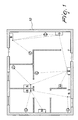
- Figure 1 is a plan view of an environment in which a plurality of fan coils are installed which are connected by the communications network according to the invention;
- Figure 2 is a block diagram of a fan coil used in the invention;
- Figure 3 is a block diagram of a user interface device used in the invention;
- Figure 4 is a diagram of a communications network according to the invention;
- Figure 5 is a diagram of the network of Figure 4 in the presence of obstacles.
- With reference to the figures, the network according to the invention comprises a plurality of fan coils which constitute the nodes of the network.
- The fan coils, equally designated by the reference letter B, are mounted on the walls or ceiling of a closed environment, such as for example the
environment 10, whose map is shown in Figure 1, according to the preferred climate-control requirements. - With reference to Figure 2, each fan coil B of the network is provided with a
means 12 for wireless communication, which preferably comprises a radiofrequency antenna. - The wireless communication means 12 is controlled by a
logic unit 13. Thelogic unit 13 comprises a memory (not shown) which stores the instructions for the operation of the fan coil as well as the instructions for exchanging messages within the network via the wireless communication means. The stored software instructions and the processing of the information contained in the messages can be executed by means of a microprocessor or equivalent circuit contained in thelogic unit 13. - The
logic unit 13 is further coupled to the conventional hydraulic andelectromechanical devices 14 of the fan coil in order to control the valves, the fan and other conventional components of the fan coil which are not described in further detail here. - Finally, the fan coil B further comprises a
power supply 15 which is connected to the mains. - The communications network comprises additional nodes constituted by an adjustment device A which is provided in the
environment 10 and by a plurality of temperature sensing units, designated equally by the reference letter C and arranged in the locations of the environment that the designer of the conditioning system deems to be ideal for reaching the selected temperature in the various locations of theenvironment 10. - The adjustment device A is preferably of the portable type and comprises a
battery 25, alogic unit 23 and awireless device 22 for radiofrequency communication with the other nodes of the network. Thelogic unit 23 comprises a memory means which contains the instructions for exchanging messages within the network via thewireless device 22 and a microprocessor or equivalent circuit for performing the stored instructions and processing the received messages. - In particular, the instructions stored in the adjustment device A comprise the reading of operating settings to be transmitted to one or more fan coils B of the communications network.
- For this purpose, the adjustment device A contains an
input device 24, for example one or more buttons, by means of which a user can enter manually the selected operating settings, which are then read and processed by thelogic unit 23 connected to the input device so as to be able to assemble the message to be sent to one or more recipient fan coils. - Optionally, the adjustment device A can contain an integrated
temperature sensor 26, which is connected to thelogic unit 23, in order to record the temperature measured in the region in which the adjustment device A is positioned and send it to the memory of thelogic unit 23 for processing. In this case, the memory of thelogic unit 23 contains instructions for introducing in the communications network messages which contain the temperature value measured by the integrated sensor. - Additional nodes of the wireless communications network according to the invention preferably correspond to respective temperature sensing units C, each of which comprises a temperature sensor, a wireless communications unit and a processing unit for transmitting reading messages via the wireless communication unit to at least one node of the network proximate to the sensing unit C. The reading messages contain a temperature value measured by the temperature sensor of the sensing unit C.
- The memories of the fan coils B and the memory means of the adjustment device A comprise a stored common database which is divided into a dynamic part and a substantially static part.
- The dynamic part of the database is updated more frequently than the static part and contains operating parameters of each of the nodes of the network, for example the measured temperature, a preset temperature, the status of the valves of the fan coil, the status of the fan of the fan coil, and the date and time. The updates of the dynamic part can occur as a consequence of the intervention of the user on the adjustment device A, as a consequence of a variation of the environmental variables detected by a sensing unit C, or in alarm or fault conditions.
- The substantially static part of the common database comprises instead network configuration parameters and is updated in case of changes to the composition of the network. These configuration parameters can comprise a progressive identification number, which is assigned to each fan coil and to each temperature sensing unit of the network during the initial configuration of the network, or settings selected by the user directly on the node.
- Since all type B nodes are aware of all the information available by means of the common database, each fan coil node is capable of deciding autonomously the actions to be performed for climate control of the environment. Therefore, there are no master or slave devices, and any fault or inability to communicate of one of said nodes does not compromise the operation of all the other nodes. Maximum efficiency of the climate control system is thus ensured in any condition.
- The common database is available in real time to all the nodes, provided that they can communicate directly or by indirect contact via other nodes.
- The communications network according to the invention is of the wireless type, since all the nodes that compose it are adapted to communicate with each other via appropriately provided wireless devices. The network according to the invention is classified as WPAN (Wireless Personal Area Network) and preferably the wireless means of communication used in the different nodes are selected so as to be able to transmit up to a distance of approximately 50 meters.
- The peculiarity of the invention consists in that said wireless network is configured so as to work as a mesh network.
- As is known, in mesh networks each node can send and receive messages from another node in its vicinity and can further act as a router in order to send received messages to a nearby node.
- By means of the forwarding process, a wireless data packet can be sent to the destination indicated therein by passing via intermediate nodes which have reliable communication links. Moreover, if one link fails due to the presence of obstacles or heavy interference, the network automatically routes the messages via alternative paths.
- In the preferred embodiment of the invention, the memories of the fan coils B store instructions not only for sending and receiving messages but also for routing messages received from at least one node of the network toward at least one other node of the network. In this manner, each fan coil can operate as a router if a message cannot reach its destination due to an obstacle or temporary interference which prevents its direct radio transmission, as shown schematically in Figures 4 and 5.
- Retransmission or routing of the received information is entrusted to the fan coils B, because by being powered directly by the mains they have no particular power consumption constraints and therefore can perform a greater number of transmissions and keep reception always active.
- Information routing is of the adaptive type and allows to relocate any node in the environment without having to reconfigure the network manually. This network architecture ensures communication, and therefore operation of the climate control system, even if obstacles or interference occur which prevent communication between two or more of nodes. The system is in fact capable of operating as long as there is, between any two nodes, an uninterrupted chain of radio links between nodes which correspond to fan coils B.
- This is possible thanks to the ability of the protocol implemented in the logic units of the fan coils B to retransmit received information toward the nodes which cannot receive it directly.
- The fan coils B, the adjustment device A and the temperature sensing units C store instructions for communicating within the network on at least two channels, in particular a main wireless channel and on a backup wireless channel, to be used in case of interference on the main channel.
- Preferably, the radio channels used are sixteen in number and the logic units of the various devices of the network are programmed to scan the power levels received on each channel when they are switched on.
- The selected main channel and backup channel are the ones having the lowest received power, i.e., the ones that have less interference when the scan is performed. However, channel selection is dynamic, and if communication problems occur during normal operation due to new interference sources, the channels can be changed.
- The logic units of all the nodes of the network according to the invention are preferably configured according to the IEEE 802.15.4 standard, so as to ensure low electric power consumption and longer life of the batteries of the network devices such as the sensing unit C or the adjustment device A.
- For access to the communication channels, the logic units of all the nodes of the network are configured according to a time-division protocol. In particular, time is divided into repetitive cycles, within which each device has an assigned slot for transmitting information. The duration of a cycle, here indicated by T_cycle, can be selected equal to approximately 4 seconds for a network with twenty-five fan coils, twenty-four temperature sensing units C and an adjustment device A.
- The time-division structure allows to avoid transmission collisions, thus increasing the life of the battery-powered nodes and more generally reducing the interference generated on the radio channels.
- Communication synchronization is dictated by one of the fan coil nodes B, which is assigned this task as a result of a priority selection algorithm based on the progressive identification number assigned during network configuration and on the visibility of the nodes and is repeated at each cycle.
- Preferably, the adjustment device A and the sensing units C are programmed, by way of appropriate stored instructions, so that the operating settings or the temperature value are input to the communications network with a periodic timing which is equal to the cycle T_cycle.
- As an alternative, the messages generated by the adjustment device A and/or by the sensing unit C are input only if the input device receives a manual command to change the operating settings and/or if the temperature sensor detects a temperature variation. The adjustment device A, in this case, reads the values that arrive from the
input device 24 or from the integrated temperature sensor every 128 ms, but the transmission of the corresponding message occurs every T_cycle, in order to save on battery consumption. - A reading every 128 ms of the temperature sensor and the transmission, if required, of the corresponding message every T_cycle are also performed by the sensing units C.
- If the device A does not work due to drained batteries or for other reasons, the network still continues to operate, maintaining the last selected settings.
- In order to further conserve the life of the batteries that supply power to the nodes A and C, the adjustment device and the sensing units C store instructions for keeping in sleep mode the respective wireless communication devices in order to activate them for transmission according to said periodic timing T_cycle, or as a consequence of the sensing of a temperature variation or of a manual command performed on the input device.
- Preferably, the adjustment device A and the sensing units C are further programmed so as to wait to receive an acknowledgment message from the fan coil B which receives the message related to the temperature variation or operating setting variation that has just been transmitted.
- The operation of the mesh network begins after a first configuration step, in which all the devices that belong to the network are placed in the environment in the preferred positions and are activated. By means of an appropriate function of the user interface, the unique serial codes and the type of the devices that belong to the network are acquired. During this step, all the devices of the same type are automatically assigned a progressive identification number (indicated by ProgIDVent and ProgIDSens, respectively, for the fan coil devices B and the sensing unit C).
- The information related to the components of the network, together with other information which configure operation (filters, associations, operating modes) are then collected in the static part of the common database and are reported to all type A and B devices of said network. In this manner, all type A and B nodes are informed of the composition of the network.
- By means of the priority selection algorithm based on the assigned progressive identification number, one fan coil is given the task of synchronizing the network and cyclically transmits the synchronization information to all the nodes B of the network.
- The fan coil B which is given the synchronization task transmits the synchronization information (timestamp) to all the other type B nodes, again according to a mesh architecture. The communication protocol used takes into account the possibility of a fault or jamming of communication of the node assigned to synchronization, and in this case the task is transferred automatically to another node as a result of a new selection.
- During the normal operation of the network, the fan coils B which receive a message regarding the update of the common database on the part of any other device of the network reply with a delay which is variable according to their progressive identifier ProgIDVent, unless they detect that any other device B has already answered. Usually, each device B waits before answering for a time which is equal to ProgIDVent x 4 ms.
- The device A or C which has received the answer from the fan coil identified by ProgIDVent enters in the next message the specific identifier ProgIDVent and authorizes the recipient fan coil to reply immediately, in order to minimize the power-on times of the device and extend the life of its batteries.
- With reference to Figures 4 and 5, during operation the fan coils B communicate continuously and exchange acknowledgment messages. The node B 1 is the one that provides communication synchronization.
- In the drawing, the solid lines represent a continuous time-division communication among the nodes, whereas the broken lines indicate communication only in the presence of an event such as the temperature variation or a manual setting, or periodic communication. The double arrows indicate communication with acknowledgment by the recipient node, while the single arrows indicate that the transmission has been ignored by the recipient node, since a node with a progressive identifier having a higher priority has answered.
- As can be seen, the node B 1 communicates continuously with all the nodes B that it can see, while the nodes B that can see the node B 1 ignore the messages received from the other nodes B because certainly these last nodes have already received an answer from the node B1, since it is the node having the highest priority.
- In the presence of an obstacle which blocks wireless communication between a node B and the node B1, the node affected by the obstacle begins to communicate with the node B which it can see and waits for an answer.
- In practice it has been found that the network architecture according to the invention fully achieves the intended aim, since a self-configuring network has been provided which does not require the presence of a network administrator or of a centralized control in order to work. Once the initial configuration has been completed, if nodes are added the network is in fact capable of detecting them autonomously.
- If one or more nodes are isolated from the rest of the network, they continue to operate on the basis of the updated information which in any case they are able to exchange and on the basis of the last received settings. For example, the fan coil can use the measurement of the ambient temperature obtained locally, optionally corrected on the basis of the variations detected previously with respect to the reference measurement.
- The network architecture thus conceived is susceptible of numerous modifications and variations, all of which are within the scope of the appended claims. All the details may further be replaced with other technically equivalent elements.
- The disclosures in
Italian Patent Application no. MI2006A000346 - Where technical features mentioned in any claim are followed by reference signs, those reference signs have been included for the sole purpose of increasing the intelligibility of the claims and accordingly such reference signs do not have any limiting effect on the interpretation of each element identified by way of example by such reference signs.
Claims (16)
- A communications network for air-conditioning systems, characterized in that it comprises a plurality of fan coils which correspond to respective wireless nodes of the network, each of said fan coils being provided with a respective wireless communications means for bidirectional communication with the other fan coils of the network and being further provided with a memory which contains instructions for exchanging messages with the nodes of said network according to a mesh-type logic by way of said wireless communications means.
- The communications network according to claim 1, wherein said memory of the fan coil comprises instructions for routing, via the wireless communication means, messages received from at least one node of the network toward at least one other node of the network.
- The communications network according to claim 1 or 2, further comprising an adjustment device which forms an additional respective wireless node of the network, said adjustment device comprising an input device for selecting operating settings of said fan coils, a device for wireless communication and a memory means which contains instructions for introducing in said communications network, via said wireless communication device, messages which contain said operating settings.
- The communications network according to claim 2 or 3, wherein said adjustment device comprises an integrated temperature sensor, said memory means of the adjustment device further comprising instructions for introducing in said communications network, via said wireless communications device, a message which contains the temperature value measured by said integrated sensor.
- The communications network according to one or more of claims 2 to 4, characterized in that said memory means of the adjustment device comprises stored instructions for transmitting said messages which contain the operating settings or the temperature value with a periodic timing, or for transmitting said messages if the input device receives a command to vary the operating settings and/or if the integrated temperature sensor detects a temperature variation.
- The communications network according to claim 5, wherein the memory means of the adjustment device contains instructions for keeping in sleep mode said wireless communications device and for activating it for transmission according to said periodic timing, or as a consequence of said variation command, or as a consequence of the detection of a temperature variation on the part of said integrated sensor, said memory means further comprising instructions for receiving, via said wireless communications device, an acknowledgment message from the fan coil which receives the message which contains the operating settings.
- The communications network according to one or more of claims 2 to 6, characterized in that said adjustment device is portable.
- The communications network according to any one of the preceding claims, comprising at least one temperature sensing unit which corresponds to an additional respective wireless node of the network, said sensing unit comprising a temperature sensor, a wireless communications unit and a processing unit for transmitting reading messages via said wireless communications unit to at least one node of the network proximate to said sensing unit, said reading messages comprising a value of the temperature measured by said temperature sensor.
- The communications network according to claim 8, wherein said processing unit comprises stored instructions for transmitting the temperature value when the temperature sensor detects a temperature variation and/or for transmitting with a periodic timing the measured temperature value.
- The communications network according to claim 9, wherein the processing unit further contains instructions for keeping in sleep mode said wireless communications unit and for activating it to transmit according to said periodic timing or as a consequence of the sensing of a temperature variation on the part of said temperature sensor, said processing unit further comprising instructions for receiving, via said wireless communications unit, an acknowledgment message from the fan coil that receives the message containing the transmitted temperature value.
- The communications network according to one or more of the preceding claims, wherein the memory of each fan coil contains instructions to keep always active in reception the wireless communication means and to activate it with a periodic timing for the transmission of said messages.
- The communications network according to one or more of the preceding claims, wherein the memories of said fan coils and the memory means of said at least one adjustment device store a common database which contains operating parameters of each one of the nodes of the network, said operating parameters comprising at least one among the following: measured temperature, preset temperature, fan coil valve status, fan coil fan status.
- The communications network according to claim 12, wherein said database further contains network configuration parameters, which comprise a progressive identification number for each fan coil and for each temperature sensing unit of the network.
- The communications network according to one or more of the preceding claims, wherein one of said fan coils is adapted to transmit via said wireless communications means a network synchronization signal, said network being configured according to a time-division protocol with a cycle which is equal to said periodic timing.
- The communications network according to claims 13 and 14, wherein said network is configured so that the fan coil adapted to transmit the synchronization signal is selected according to a priority selection algorithm which is based on said progressive identification number and on the visibility of the nodes of the network, said algorithm being repeated with said periodic timing.
- The communications network according to one or more of the preceding claims, wherein the fan coils, the adjustment device and said at least one temperature sensing unit store instructions for communicating over said network on a main wireless channel and a backup wireless channel to be used in case of interference on the main channel.
Priority Applications (1)
| Application Number | Priority Date | Filing Date | Title |
|---|---|---|---|
| PL07003206T PL1826498T3 (en) | 2006-02-27 | 2007-02-15 | Network of wireless fan coils |
Applications Claiming Priority (1)
| Application Number | Priority Date | Filing Date | Title |
|---|---|---|---|
| IT000346A ITMI20060346A1 (en) | 2006-02-27 | 2006-02-27 | NETWORK OF WIRELESS FANS |
Publications (2)
| Publication Number | Publication Date |
|---|---|
| EP1826498A1 true EP1826498A1 (en) | 2007-08-29 |
| EP1826498B1 EP1826498B1 (en) | 2009-11-11 |
Family
ID=38002096
Family Applications (1)
| Application Number | Title | Priority Date | Filing Date |
|---|---|---|---|
| EP07003206A Not-in-force EP1826498B1 (en) | 2006-02-27 | 2007-02-15 | Network of wireless fan coils |
Country Status (6)
| Country | Link |
|---|---|
| EP (1) | EP1826498B1 (en) |
| AT (1) | ATE448451T1 (en) |
| DE (1) | DE602007003123D1 (en) |
| ES (1) | ES2337188T3 (en) |
| IT (1) | ITMI20060346A1 (en) |
| PL (1) | PL1826498T3 (en) |
Cited By (8)
| Publication number | Priority date | Publication date | Assignee | Title |
|---|---|---|---|---|
| GB2475540A (en) * | 2009-11-23 | 2011-05-25 | Charles Hugh Carr Wyn-Davies | Energy management system |
| US20120248893A1 (en) * | 2011-03-29 | 2012-10-04 | Triune Ip Llc | Wireless Power Transmittal |
| EP2166292A3 (en) * | 2008-09-17 | 2018-08-15 | Samsung Electronics Co., Ltd. | Communication method for air conditioner using different communication schemes |
| EP3462095A1 (en) * | 2017-09-28 | 2019-04-03 | LG Electronics Inc. | Control method of air conditioner system |
| EP3462096A1 (en) * | 2017-09-28 | 2019-04-03 | LG Electronics Inc. | Control method of air conditioner system |
| US10854378B2 (en) | 2009-02-23 | 2020-12-01 | Triune Ip Llc | Wireless power transmittal |
| US11343873B2 (en) * | 2018-01-15 | 2022-05-24 | Gcs Gmbh | Blower system, blower and method for operating and for installing a blower |
| SE2350385A1 (en) * | 2023-03-31 | 2024-10-01 | Munters Europe Ab | A system and method for climate control within a space |
Citations (6)
| Publication number | Priority date | Publication date | Assignee | Title |
|---|---|---|---|---|
| US5711480A (en) | 1996-10-15 | 1998-01-27 | Carrier Corporation | Low-cost wireless HVAC systems |
| US20030227220A1 (en) * | 2000-08-04 | 2003-12-11 | Biskup James H | Security and energy control system |
| US20040088082A1 (en) * | 2002-01-28 | 2004-05-06 | Osman Ahmed | Building control system and fume hood system for use therein having reduced wiring requirements |
| JP2004200857A (en) * | 2002-12-17 | 2004-07-15 | Daikin Ind Ltd | Equipment management system, packet priority control method, network management device, air conditioner indoor unit, communication service providing method, and communication service providing system |
| EP1445550A1 (en) * | 2001-10-26 | 2004-08-11 | Daikin Industries, Ltd. | Air conditioner control system and air conditioner |
| US20050040943A1 (en) * | 2003-08-22 | 2005-02-24 | Honeywell International, Inc. | RF interconnected HVAC system and security system |
-
2006
- 2006-02-27 IT IT000346A patent/ITMI20060346A1/en unknown
-
2007
- 2007-02-15 AT AT07003206T patent/ATE448451T1/en active
- 2007-02-15 EP EP07003206A patent/EP1826498B1/en not_active Not-in-force
- 2007-02-15 ES ES07003206T patent/ES2337188T3/en active Active
- 2007-02-15 PL PL07003206T patent/PL1826498T3/en unknown
- 2007-02-15 DE DE602007003123T patent/DE602007003123D1/en active Active
Patent Citations (6)
| Publication number | Priority date | Publication date | Assignee | Title |
|---|---|---|---|---|
| US5711480A (en) | 1996-10-15 | 1998-01-27 | Carrier Corporation | Low-cost wireless HVAC systems |
| US20030227220A1 (en) * | 2000-08-04 | 2003-12-11 | Biskup James H | Security and energy control system |
| EP1445550A1 (en) * | 2001-10-26 | 2004-08-11 | Daikin Industries, Ltd. | Air conditioner control system and air conditioner |
| US20040088082A1 (en) * | 2002-01-28 | 2004-05-06 | Osman Ahmed | Building control system and fume hood system for use therein having reduced wiring requirements |
| JP2004200857A (en) * | 2002-12-17 | 2004-07-15 | Daikin Ind Ltd | Equipment management system, packet priority control method, network management device, air conditioner indoor unit, communication service providing method, and communication service providing system |
| US20050040943A1 (en) * | 2003-08-22 | 2005-02-24 | Honeywell International, Inc. | RF interconnected HVAC system and security system |
Cited By (12)
| Publication number | Priority date | Publication date | Assignee | Title |
|---|---|---|---|---|
| EP2166292A3 (en) * | 2008-09-17 | 2018-08-15 | Samsung Electronics Co., Ltd. | Communication method for air conditioner using different communication schemes |
| US10854378B2 (en) | 2009-02-23 | 2020-12-01 | Triune Ip Llc | Wireless power transmittal |
| US11309126B2 (en) | 2009-02-23 | 2022-04-19 | Triune Systems, LLC | Wireless power transmittal |
| GB2475540A (en) * | 2009-11-23 | 2011-05-25 | Charles Hugh Carr Wyn-Davies | Energy management system |
| US20120248893A1 (en) * | 2011-03-29 | 2012-10-04 | Triune Ip Llc | Wireless Power Transmittal |
| US9530555B2 (en) * | 2011-03-29 | 2016-12-27 | Triune Systems, LLC | Wireless power transmittal |
| EP3462095A1 (en) * | 2017-09-28 | 2019-04-03 | LG Electronics Inc. | Control method of air conditioner system |
| EP3462096A1 (en) * | 2017-09-28 | 2019-04-03 | LG Electronics Inc. | Control method of air conditioner system |
| US10760811B2 (en) | 2017-09-28 | 2020-09-01 | Lg Electronics Inc. | Method for controlling air conditioner system |
| US10852024B2 (en) | 2017-09-28 | 2020-12-01 | Lg Electronics Inc. | Method for controlling air conditioner system |
| US11343873B2 (en) * | 2018-01-15 | 2022-05-24 | Gcs Gmbh | Blower system, blower and method for operating and for installing a blower |
| SE2350385A1 (en) * | 2023-03-31 | 2024-10-01 | Munters Europe Ab | A system and method for climate control within a space |
Also Published As
| Publication number | Publication date |
|---|---|
| PL1826498T3 (en) | 2010-04-30 |
| ITMI20060346A1 (en) | 2007-08-28 |
| DE602007003123D1 (en) | 2009-12-24 |
| ES2337188T3 (en) | 2010-04-21 |
| ATE448451T1 (en) | 2009-11-15 |
| EP1826498B1 (en) | 2009-11-11 |
Similar Documents
| Publication | Publication Date | Title |
|---|---|---|
| EP1826498B1 (en) | Network of wireless fan coils | |
| EP1783959B1 (en) | Self-healing control network for building automation systems | |
| US10379504B2 (en) | Method and apparatus to optimize power to maximize performance of mesh sensors and control networks | |
| CA2661915C (en) | Method and device for binding an automation component within a building automation system | |
| CA2662014C (en) | Binding methods and devices in a building automation system | |
| CA2236569C (en) | Method for installing a wireless network | |
| US20090083416A1 (en) | Methods to verify wireless node placement for reliable communication in wireless sensor control networks | |
| KR101202914B1 (en) | Method and device for communicating change-of-value information in a building automation system | |
| US20250202603A1 (en) | Assigning router devices in a mesh network | |
| CN101939949B (en) | Method and tool for wireless communications with sleeping devices in a wireless sensor control network | |
| CA3144634A1 (en) | Network formation for a load control system | |
| GB2512781A (en) | Network configuration | |
| EP2428000A1 (en) | Method for controlling transmissions from a resource-restricted device, and batteryless device | |
| EP2169995A1 (en) | Radio network system and control node switching method | |
| KR101448299B1 (en) | Wireless each room control system using boiler control module | |
| KR20070122387A (en) | Communication method in home automation equipment | |
| EP3311607A2 (en) | Smart home system | |
| CN103576664A (en) | Automation component for transmitting value change information in intelligent household system and method | |
| KR20200089262A (en) | Wireless communication device and process management method for process control in factory | |
| WO2013132410A1 (en) | System and method of transmitting a message to a wireless limited node | |
| CA2836941C (en) | Binding methods and devices in a building automation system | |
| JP2009100040A (en) | Wireless telecontrol system |
Legal Events
| Date | Code | Title | Description |
|---|---|---|---|
| PUAI | Public reference made under article 153(3) epc to a published international application that has entered the european phase |
Free format text: ORIGINAL CODE: 0009012 |
|
| AK | Designated contracting states |
Kind code of ref document: A1 Designated state(s): AT BE BG CH CY CZ DE DK EE ES FI FR GB GR HU IE IS IT LI LT LU LV MC NL PL PT RO SE SI SK TR |
|
| AX | Request for extension of the european patent |
Extension state: AL BA HR MK YU |
|
| 17P | Request for examination filed |
Effective date: 20080123 |
|
| AKX | Designation fees paid |
Designated state(s): AT BE BG CH CY CZ DE DK EE ES FI FR GB GR HU IE IS IT LI LT LU LV MC NL PL PT RO SE SI SK TR |
|
| GRAP | Despatch of communication of intention to grant a patent |
Free format text: ORIGINAL CODE: EPIDOSNIGR1 |
|
| GRAS | Grant fee paid |
Free format text: ORIGINAL CODE: EPIDOSNIGR3 |
|
| GRAA | (expected) grant |
Free format text: ORIGINAL CODE: 0009210 |
|
| AK | Designated contracting states |
Kind code of ref document: B1 Designated state(s): AT BE BG CH CY CZ DE DK EE ES FI FR GB GR HU IE IS IT LI LT LU LV MC NL PL PT RO SE SI SK TR |
|
| REG | Reference to a national code |
Ref country code: GB Ref legal event code: FG4D |
|
| REG | Reference to a national code |
Ref country code: CH Ref legal event code: EP |
|
| REG | Reference to a national code |
Ref country code: IE Ref legal event code: FG4D |
|
| REF | Corresponds to: |
Ref document number: 602007003123 Country of ref document: DE Date of ref document: 20091224 Kind code of ref document: P |
|
| REG | Reference to a national code |
Ref country code: SE Ref legal event code: TRGR |
|
| REG | Reference to a national code |
Ref country code: RO Ref legal event code: EPE |
|
| NLV1 | Nl: lapsed or annulled due to failure to fulfill the requirements of art. 29p and 29m of the patents act | ||
| REG | Reference to a national code |
Ref country code: ES Ref legal event code: FG2A Ref document number: 2337188 Country of ref document: ES Kind code of ref document: T3 |
|
| LTIE | Lt: invalidation of european patent or patent extension |
Effective date: 20091111 |
|
| PG25 | Lapsed in a contracting state [announced via postgrant information from national office to epo] |
Ref country code: IS Free format text: LAPSE BECAUSE OF FAILURE TO SUBMIT A TRANSLATION OF THE DESCRIPTION OR TO PAY THE FEE WITHIN THE PRESCRIBED TIME-LIMIT Effective date: 20100311 Ref country code: FI Free format text: LAPSE BECAUSE OF FAILURE TO SUBMIT A TRANSLATION OF THE DESCRIPTION OR TO PAY THE FEE WITHIN THE PRESCRIBED TIME-LIMIT Effective date: 20091111 Ref country code: PT Free format text: LAPSE BECAUSE OF FAILURE TO SUBMIT A TRANSLATION OF THE DESCRIPTION OR TO PAY THE FEE WITHIN THE PRESCRIBED TIME-LIMIT Effective date: 20100311 Ref country code: LT Free format text: LAPSE BECAUSE OF FAILURE TO SUBMIT A TRANSLATION OF THE DESCRIPTION OR TO PAY THE FEE WITHIN THE PRESCRIBED TIME-LIMIT Effective date: 20091111 |
|
| REG | Reference to a national code |
Ref country code: PL Ref legal event code: T3 |
|
| PG25 | Lapsed in a contracting state [announced via postgrant information from national office to epo] |
Ref country code: LV Free format text: LAPSE BECAUSE OF FAILURE TO SUBMIT A TRANSLATION OF THE DESCRIPTION OR TO PAY THE FEE WITHIN THE PRESCRIBED TIME-LIMIT Effective date: 20091111 Ref country code: SI Free format text: LAPSE BECAUSE OF FAILURE TO SUBMIT A TRANSLATION OF THE DESCRIPTION OR TO PAY THE FEE WITHIN THE PRESCRIBED TIME-LIMIT Effective date: 20091111 Ref country code: CY Free format text: LAPSE BECAUSE OF FAILURE TO SUBMIT A TRANSLATION OF THE DESCRIPTION OR TO PAY THE FEE WITHIN THE PRESCRIBED TIME-LIMIT Effective date: 20091111 |
|
| PG25 | Lapsed in a contracting state [announced via postgrant information from national office to epo] |
Ref country code: BE Free format text: LAPSE BECAUSE OF FAILURE TO SUBMIT A TRANSLATION OF THE DESCRIPTION OR TO PAY THE FEE WITHIN THE PRESCRIBED TIME-LIMIT Effective date: 20091111 |
|
| PG25 | Lapsed in a contracting state [announced via postgrant information from national office to epo] |
Ref country code: EE Free format text: LAPSE BECAUSE OF FAILURE TO SUBMIT A TRANSLATION OF THE DESCRIPTION OR TO PAY THE FEE WITHIN THE PRESCRIBED TIME-LIMIT Effective date: 20091111 Ref country code: DK Free format text: LAPSE BECAUSE OF FAILURE TO SUBMIT A TRANSLATION OF THE DESCRIPTION OR TO PAY THE FEE WITHIN THE PRESCRIBED TIME-LIMIT Effective date: 20091111 Ref country code: BG Free format text: LAPSE BECAUSE OF FAILURE TO SUBMIT A TRANSLATION OF THE DESCRIPTION OR TO PAY THE FEE WITHIN THE PRESCRIBED TIME-LIMIT Effective date: 20100211 |
|
| REG | Reference to a national code |
Ref country code: HU Ref legal event code: AG4A Ref document number: E007837 Country of ref document: HU |
|
| PG25 | Lapsed in a contracting state [announced via postgrant information from national office to epo] |
Ref country code: SK Free format text: LAPSE BECAUSE OF FAILURE TO SUBMIT A TRANSLATION OF THE DESCRIPTION OR TO PAY THE FEE WITHIN THE PRESCRIBED TIME-LIMIT Effective date: 20091111 Ref country code: CZ Free format text: LAPSE BECAUSE OF FAILURE TO SUBMIT A TRANSLATION OF THE DESCRIPTION OR TO PAY THE FEE WITHIN THE PRESCRIBED TIME-LIMIT Effective date: 20091111 |
|
| PLBE | No opposition filed within time limit |
Free format text: ORIGINAL CODE: 0009261 |
|
| STAA | Information on the status of an ep patent application or granted ep patent |
Free format text: STATUS: NO OPPOSITION FILED WITHIN TIME LIMIT |
|
| 26N | No opposition filed |
Effective date: 20100812 |
|
| PG25 | Lapsed in a contracting state [announced via postgrant information from national office to epo] |
Ref country code: MC Free format text: LAPSE BECAUSE OF NON-PAYMENT OF DUE FEES Effective date: 20100301 Ref country code: GR Free format text: LAPSE BECAUSE OF FAILURE TO SUBMIT A TRANSLATION OF THE DESCRIPTION OR TO PAY THE FEE WITHIN THE PRESCRIBED TIME-LIMIT Effective date: 20100212 |
|
| PG25 | Lapsed in a contracting state [announced via postgrant information from national office to epo] |
Ref country code: IE Free format text: LAPSE BECAUSE OF NON-PAYMENT OF DUE FEES Effective date: 20100215 |
|
| REG | Reference to a national code |
Ref country code: CH Ref legal event code: PL |
|
| PG25 | Lapsed in a contracting state [announced via postgrant information from national office to epo] |
Ref country code: LI Free format text: LAPSE BECAUSE OF NON-PAYMENT OF DUE FEES Effective date: 20110228 Ref country code: CH Free format text: LAPSE BECAUSE OF NON-PAYMENT OF DUE FEES Effective date: 20110228 |
|
| PG25 | Lapsed in a contracting state [announced via postgrant information from national office to epo] |
Ref country code: NL Free format text: LAPSE BECAUSE OF FAILURE TO SUBMIT A TRANSLATION OF THE DESCRIPTION OR TO PAY THE FEE WITHIN THE PRESCRIBED TIME-LIMIT Effective date: 20091111 Ref country code: LU Free format text: LAPSE BECAUSE OF NON-PAYMENT OF DUE FEES Effective date: 20100215 |
|
| PG25 | Lapsed in a contracting state [announced via postgrant information from national office to epo] |
Ref country code: TR Free format text: LAPSE BECAUSE OF FAILURE TO SUBMIT A TRANSLATION OF THE DESCRIPTION OR TO PAY THE FEE WITHIN THE PRESCRIBED TIME-LIMIT Effective date: 20091111 |
|
| REG | Reference to a national code |
Ref country code: DE Ref legal event code: R082 Ref document number: 602007003123 Country of ref document: DE Representative=s name: GRAMM, LINS & PARTNER PATENT- UND RECHTSANWAEL, DE |
|
| REG | Reference to a national code |
Ref country code: FR Ref legal event code: PLFP Year of fee payment: 10 |
|
| PGFP | Annual fee paid to national office [announced via postgrant information from national office to epo] |
Ref country code: GB Payment date: 20160628 Year of fee payment: 10 |
|
| PGFP | Annual fee paid to national office [announced via postgrant information from national office to epo] |
Ref country code: SE Payment date: 20160627 Year of fee payment: 10 Ref country code: RO Payment date: 20160628 Year of fee payment: 10 Ref country code: AT Payment date: 20160629 Year of fee payment: 10 Ref country code: PL Payment date: 20160628 Year of fee payment: 10 Ref country code: FR Payment date: 20160630 Year of fee payment: 10 |
|
| PGFP | Annual fee paid to national office [announced via postgrant information from national office to epo] |
Ref country code: IT Payment date: 20160629 Year of fee payment: 10 Ref country code: DE Payment date: 20160629 Year of fee payment: 10 |
|
| PGFP | Annual fee paid to national office [announced via postgrant information from national office to epo] |
Ref country code: HU Payment date: 20160705 Year of fee payment: 10 |
|
| PGFP | Annual fee paid to national office [announced via postgrant information from national office to epo] |
Ref country code: ES Payment date: 20160629 Year of fee payment: 10 |
|
| REG | Reference to a national code |
Ref country code: DE Ref legal event code: R119 Ref document number: 602007003123 Country of ref document: DE |
|
| REG | Reference to a national code |
Ref country code: SE Ref legal event code: EUG |
|
| REG | Reference to a national code |
Ref country code: AT Ref legal event code: MM01 Ref document number: 448451 Country of ref document: AT Kind code of ref document: T Effective date: 20170215 |
|
| GBPC | Gb: european patent ceased through non-payment of renewal fee |
Effective date: 20170215 |
|
| PG25 | Lapsed in a contracting state [announced via postgrant information from national office to epo] |
Ref country code: RO Free format text: LAPSE BECAUSE OF NON-PAYMENT OF DUE FEES Effective date: 20170215 Ref country code: AT Free format text: LAPSE BECAUSE OF NON-PAYMENT OF DUE FEES Effective date: 20170215 |
|
| PG25 | Lapsed in a contracting state [announced via postgrant information from national office to epo] |
Ref country code: SE Free format text: LAPSE BECAUSE OF NON-PAYMENT OF DUE FEES Effective date: 20170216 Ref country code: HU Free format text: LAPSE BECAUSE OF NON-PAYMENT OF DUE FEES Effective date: 20170216 |
|
| REG | Reference to a national code |
Ref country code: FR Ref legal event code: ST Effective date: 20171031 |
|
| PG25 | Lapsed in a contracting state [announced via postgrant information from national office to epo] |
Ref country code: DE Free format text: LAPSE BECAUSE OF NON-PAYMENT OF DUE FEES Effective date: 20170901 Ref country code: FR Free format text: LAPSE BECAUSE OF NON-PAYMENT OF DUE FEES Effective date: 20170228 |
|
| PG25 | Lapsed in a contracting state [announced via postgrant information from national office to epo] |
Ref country code: GB Free format text: LAPSE BECAUSE OF NON-PAYMENT OF DUE FEES Effective date: 20170215 Ref country code: IT Free format text: LAPSE BECAUSE OF NON-PAYMENT OF DUE FEES Effective date: 20170215 |
|
| REG | Reference to a national code |
Ref country code: ES Ref legal event code: FD2A Effective date: 20180626 |
|
| PG25 | Lapsed in a contracting state [announced via postgrant information from national office to epo] |
Ref country code: ES Free format text: LAPSE BECAUSE OF NON-PAYMENT OF DUE FEES Effective date: 20170216 |
|
| PG25 | Lapsed in a contracting state [announced via postgrant information from national office to epo] |
Ref country code: PL Free format text: LAPSE BECAUSE OF NON-PAYMENT OF DUE FEES Effective date: 20170215 |
|
| P01 | Opt-out of the competence of the unified patent court (upc) registered |
Effective date: 20230527 |