EP1826371A1 - Particulate trap regeneration system and method - Google Patents
Particulate trap regeneration system and method Download PDFInfo
- Publication number
- EP1826371A1 EP1826371A1 EP07003801A EP07003801A EP1826371A1 EP 1826371 A1 EP1826371 A1 EP 1826371A1 EP 07003801 A EP07003801 A EP 07003801A EP 07003801 A EP07003801 A EP 07003801A EP 1826371 A1 EP1826371 A1 EP 1826371A1
- Authority
- EP
- European Patent Office
- Prior art keywords
- particulate trap
- air
- exhaust
- wall
- engine
- Prior art date
- Legal status (The legal status is an assumption and is not a legal conclusion. Google has not performed a legal analysis and makes no representation as to the accuracy of the status listed.)
- Withdrawn
Links
Images

Classifications
-
- F—MECHANICAL ENGINEERING; LIGHTING; HEATING; WEAPONS; BLASTING
- F01—MACHINES OR ENGINES IN GENERAL; ENGINE PLANTS IN GENERAL; STEAM ENGINES
- F01N—GAS-FLOW SILENCERS OR EXHAUST APPARATUS FOR MACHINES OR ENGINES IN GENERAL; GAS-FLOW SILENCERS OR EXHAUST APPARATUS FOR INTERNAL-COMBUSTION ENGINES
- F01N3/00—Exhaust or silencing apparatus having means for purifying, rendering innocuous, or otherwise treating exhaust
- F01N3/02—Exhaust or silencing apparatus having means for purifying, rendering innocuous, or otherwise treating exhaust for cooling, or for removing solid constituents of, exhaust
- F01N3/021—Exhaust or silencing apparatus having means for purifying, rendering innocuous, or otherwise treating exhaust for cooling, or for removing solid constituents of, exhaust by means of filters
- F01N3/023—Exhaust or silencing apparatus having means for purifying, rendering innocuous, or otherwise treating exhaust for cooling, or for removing solid constituents of, exhaust by means of filters using means for regenerating the filters, e.g. by burning trapped particles
- F01N3/025—Exhaust or silencing apparatus having means for purifying, rendering innocuous, or otherwise treating exhaust for cooling, or for removing solid constituents of, exhaust by means of filters using means for regenerating the filters, e.g. by burning trapped particles using fuel burner or by adding fuel to exhaust
-
- F—MECHANICAL ENGINEERING; LIGHTING; HEATING; WEAPONS; BLASTING
- F01—MACHINES OR ENGINES IN GENERAL; ENGINE PLANTS IN GENERAL; STEAM ENGINES
- F01N—GAS-FLOW SILENCERS OR EXHAUST APPARATUS FOR MACHINES OR ENGINES IN GENERAL; GAS-FLOW SILENCERS OR EXHAUST APPARATUS FOR INTERNAL-COMBUSTION ENGINES
- F01N13/00—Exhaust or silencing apparatus characterised by constructional features
- F01N13/14—Exhaust or silencing apparatus characterised by constructional features having thermal insulation
- F01N13/141—Double-walled exhaust pipes or housings
- F01N13/143—Double-walled exhaust pipes or housings with air filling the space between both walls
-
- F—MECHANICAL ENGINEERING; LIGHTING; HEATING; WEAPONS; BLASTING
- F01—MACHINES OR ENGINES IN GENERAL; ENGINE PLANTS IN GENERAL; STEAM ENGINES
- F01N—GAS-FLOW SILENCERS OR EXHAUST APPARATUS FOR MACHINES OR ENGINES IN GENERAL; GAS-FLOW SILENCERS OR EXHAUST APPARATUS FOR INTERNAL-COMBUSTION ENGINES
- F01N3/00—Exhaust or silencing apparatus having means for purifying, rendering innocuous, or otherwise treating exhaust
- F01N3/02—Exhaust or silencing apparatus having means for purifying, rendering innocuous, or otherwise treating exhaust for cooling, or for removing solid constituents of, exhaust
- F01N3/021—Exhaust or silencing apparatus having means for purifying, rendering innocuous, or otherwise treating exhaust for cooling, or for removing solid constituents of, exhaust by means of filters
- F01N3/023—Exhaust or silencing apparatus having means for purifying, rendering innocuous, or otherwise treating exhaust for cooling, or for removing solid constituents of, exhaust by means of filters using means for regenerating the filters, e.g. by burning trapped particles
- F01N3/025—Exhaust or silencing apparatus having means for purifying, rendering innocuous, or otherwise treating exhaust for cooling, or for removing solid constituents of, exhaust by means of filters using means for regenerating the filters, e.g. by burning trapped particles using fuel burner or by adding fuel to exhaust
- F01N3/0253—Exhaust or silencing apparatus having means for purifying, rendering innocuous, or otherwise treating exhaust for cooling, or for removing solid constituents of, exhaust by means of filters using means for regenerating the filters, e.g. by burning trapped particles using fuel burner or by adding fuel to exhaust adding fuel to exhaust gases
-
- F—MECHANICAL ENGINEERING; LIGHTING; HEATING; WEAPONS; BLASTING
- F01—MACHINES OR ENGINES IN GENERAL; ENGINE PLANTS IN GENERAL; STEAM ENGINES
- F01N—GAS-FLOW SILENCERS OR EXHAUST APPARATUS FOR MACHINES OR ENGINES IN GENERAL; GAS-FLOW SILENCERS OR EXHAUST APPARATUS FOR INTERNAL-COMBUSTION ENGINES
- F01N3/00—Exhaust or silencing apparatus having means for purifying, rendering innocuous, or otherwise treating exhaust
- F01N3/08—Exhaust or silencing apparatus having means for purifying, rendering innocuous, or otherwise treating exhaust for rendering innocuous
- F01N3/10—Exhaust or silencing apparatus having means for purifying, rendering innocuous, or otherwise treating exhaust for rendering innocuous by thermal or catalytic conversion of noxious components of exhaust
- F01N3/24—Exhaust or silencing apparatus having means for purifying, rendering innocuous, or otherwise treating exhaust for rendering innocuous by thermal or catalytic conversion of noxious components of exhaust characterised by constructional aspects of converting apparatus
- F01N3/30—Arrangements for supply of additional air
- F01N3/306—Preheating additional air
-
- F—MECHANICAL ENGINEERING; LIGHTING; HEATING; WEAPONS; BLASTING
- F01—MACHINES OR ENGINES IN GENERAL; ENGINE PLANTS IN GENERAL; STEAM ENGINES
- F01N—GAS-FLOW SILENCERS OR EXHAUST APPARATUS FOR MACHINES OR ENGINES IN GENERAL; GAS-FLOW SILENCERS OR EXHAUST APPARATUS FOR INTERNAL-COMBUSTION ENGINES
- F01N9/00—Electrical control of exhaust gas treating apparatus
- F01N9/002—Electrical control of exhaust gas treating apparatus of filter regeneration
-
- F—MECHANICAL ENGINEERING; LIGHTING; HEATING; WEAPONS; BLASTING
- F01—MACHINES OR ENGINES IN GENERAL; ENGINE PLANTS IN GENERAL; STEAM ENGINES
- F01N—GAS-FLOW SILENCERS OR EXHAUST APPARATUS FOR MACHINES OR ENGINES IN GENERAL; GAS-FLOW SILENCERS OR EXHAUST APPARATUS FOR INTERNAL-COMBUSTION ENGINES
- F01N2240/00—Combination or association of two or more different exhaust treating devices, or of at least one such device with an auxiliary device, not covered by indexing codes F01N2230/00 or F01N2250/00, one of the devices being
- F01N2240/14—Combination or association of two or more different exhaust treating devices, or of at least one such device with an auxiliary device, not covered by indexing codes F01N2230/00 or F01N2250/00, one of the devices being a fuel burner
-
- F—MECHANICAL ENGINEERING; LIGHTING; HEATING; WEAPONS; BLASTING
- F01—MACHINES OR ENGINES IN GENERAL; ENGINE PLANTS IN GENERAL; STEAM ENGINES
- F01N—GAS-FLOW SILENCERS OR EXHAUST APPARATUS FOR MACHINES OR ENGINES IN GENERAL; GAS-FLOW SILENCERS OR EXHAUST APPARATUS FOR INTERNAL-COMBUSTION ENGINES
- F01N2470/00—Structure or shape of exhaust gas passages, pipes or tubes
- F01N2470/24—Concentric tubes or tubes being concentric to housing, e.g. telescopically assembled
-
- F—MECHANICAL ENGINEERING; LIGHTING; HEATING; WEAPONS; BLASTING
- F01—MACHINES OR ENGINES IN GENERAL; ENGINE PLANTS IN GENERAL; STEAM ENGINES
- F01N—GAS-FLOW SILENCERS OR EXHAUST APPARATUS FOR MACHINES OR ENGINES IN GENERAL; GAS-FLOW SILENCERS OR EXHAUST APPARATUS FOR INTERNAL-COMBUSTION ENGINES
- F01N3/00—Exhaust or silencing apparatus having means for purifying, rendering innocuous, or otherwise treating exhaust
- F01N3/02—Exhaust or silencing apparatus having means for purifying, rendering innocuous, or otherwise treating exhaust for cooling, or for removing solid constituents of, exhaust
- F01N3/021—Exhaust or silencing apparatus having means for purifying, rendering innocuous, or otherwise treating exhaust for cooling, or for removing solid constituents of, exhaust by means of filters
- F01N3/023—Exhaust or silencing apparatus having means for purifying, rendering innocuous, or otherwise treating exhaust for cooling, or for removing solid constituents of, exhaust by means of filters using means for regenerating the filters, e.g. by burning trapped particles
- F01N3/029—Exhaust or silencing apparatus having means for purifying, rendering innocuous, or otherwise treating exhaust for cooling, or for removing solid constituents of, exhaust by means of filters using means for regenerating the filters, e.g. by burning trapped particles by adding non-fuel substances to exhaust
-
- F—MECHANICAL ENGINEERING; LIGHTING; HEATING; WEAPONS; BLASTING
- F01—MACHINES OR ENGINES IN GENERAL; ENGINE PLANTS IN GENERAL; STEAM ENGINES
- F01N—GAS-FLOW SILENCERS OR EXHAUST APPARATUS FOR MACHINES OR ENGINES IN GENERAL; GAS-FLOW SILENCERS OR EXHAUST APPARATUS FOR INTERNAL-COMBUSTION ENGINES
- F01N3/00—Exhaust or silencing apparatus having means for purifying, rendering innocuous, or otherwise treating exhaust
- F01N3/08—Exhaust or silencing apparatus having means for purifying, rendering innocuous, or otherwise treating exhaust for rendering innocuous
- F01N3/10—Exhaust or silencing apparatus having means for purifying, rendering innocuous, or otherwise treating exhaust for rendering innocuous by thermal or catalytic conversion of noxious components of exhaust
- F01N3/24—Exhaust or silencing apparatus having means for purifying, rendering innocuous, or otherwise treating exhaust for rendering innocuous by thermal or catalytic conversion of noxious components of exhaust characterised by constructional aspects of converting apparatus
- F01N3/30—Arrangements for supply of additional air
-
- F—MECHANICAL ENGINEERING; LIGHTING; HEATING; WEAPONS; BLASTING
- F01—MACHINES OR ENGINES IN GENERAL; ENGINE PLANTS IN GENERAL; STEAM ENGINES
- F01N—GAS-FLOW SILENCERS OR EXHAUST APPARATUS FOR MACHINES OR ENGINES IN GENERAL; GAS-FLOW SILENCERS OR EXHAUST APPARATUS FOR INTERNAL-COMBUSTION ENGINES
- F01N3/00—Exhaust or silencing apparatus having means for purifying, rendering innocuous, or otherwise treating exhaust
- F01N3/08—Exhaust or silencing apparatus having means for purifying, rendering innocuous, or otherwise treating exhaust for rendering innocuous
- F01N3/10—Exhaust or silencing apparatus having means for purifying, rendering innocuous, or otherwise treating exhaust for rendering innocuous by thermal or catalytic conversion of noxious components of exhaust
- F01N3/24—Exhaust or silencing apparatus having means for purifying, rendering innocuous, or otherwise treating exhaust for rendering innocuous by thermal or catalytic conversion of noxious components of exhaust characterised by constructional aspects of converting apparatus
- F01N3/30—Arrangements for supply of additional air
- F01N3/32—Arrangements for supply of additional air using air pump
-
- Y—GENERAL TAGGING OF NEW TECHNOLOGICAL DEVELOPMENTS; GENERAL TAGGING OF CROSS-SECTIONAL TECHNOLOGIES SPANNING OVER SEVERAL SECTIONS OF THE IPC; TECHNICAL SUBJECTS COVERED BY FORMER USPC CROSS-REFERENCE ART COLLECTIONS [XRACs] AND DIGESTS
- Y02—TECHNOLOGIES OR APPLICATIONS FOR MITIGATION OR ADAPTATION AGAINST CLIMATE CHANGE
- Y02T—CLIMATE CHANGE MITIGATION TECHNOLOGIES RELATED TO TRANSPORTATION
- Y02T10/00—Road transport of goods or passengers
- Y02T10/10—Internal combustion engine [ICE] based vehicles
- Y02T10/40—Engine management systems
Definitions
- the present invention relates to management of particulates in diesel engine exhaust, and more particularly to a particulate trap regeneration system.
- Diesel engine systems normally incorporate a particulate trap having a filter that captures particulates from the exhaust.
- the trap becomes too full to filter exhaust effectively and requires regeneration before it can accumulate more particulate matter, Regeneration is usually conducted by burning the particulates within the trap, which requires an external burner to increase the temperature of the particulates.
- the present invention is directed to a particulate trap regeneration system having a simplified configuration.
- the system includes an exhaust pipe that is connected between an engine and a particulate trap and an air pump that is connected to the exhaust pipe near the engine.
- a fuel injector and a burner supply fuel and heat to the trap so that the particulates in the trap can be burned off.
- the exhaust pipe includes two channels, one of which carries exhaust from the engine and the other of which carries air from the pump.
- the two channels have one common wall so that heat from the exhaust is absorbed by the air from the air pump. Because the air entering the trap is at the exhaust temperature, the burner requires less energy to raise the temperature of the particulates sufficiently to promote burning.
- the exhaust pipe has a double-walled configuration where the exhaust travels within the inner portion of the pipe and the air travels within the space between the walls. This configuration also keeps the outside of the exhaust pipe cool, improving safety and durability.
- the invention By capturing the heat from the exhaust into air entering the particulate trap, the invention is efficient to operate and also has a simpler structure than currently known particulate trap regeneration systems.
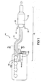
- Figure 1 is a schematic diagram of an engine and a particulate trap regeneration system according to one embodiment of the invention.
- FIG 2 is a more detailed schematic diagram of the air pump and the exhaust pipe in Figure 1;
- Figure 3 is a cross-sectional diagram of an alternative exhaust pipe configuration.
- Figure 1 shows an engine system 10 that incorporates a particulate trap regeneration system 12 according to one embodiment of the invention.
- the engine system 10 includes an engine 14 having an exhaust manifold 16 that sends exhaust through an exhaust pipe 18.
- the exhaust pipe 18 has a double-walled 19a, 19b structure that keeps the outside of the exhaust pipe 18 relatively cool ( Figure 2).
- the double walled exhaust pipe 18 also provides a space 19c between the walls for air to flow through and be heated by heat radiating through the inner wall 19b from the exhaust.
- Note that other exhaust pipe configurations are possible without departing from the scope of the invention as long as there are two pipe channels that share at least one wall through which heat from the exhaust in one channel is captured by air traveling through the adjoining channel.
- the exhaust pipe 18 may include a plurality of fins 19c that extend radially between the inner and outer walls 19b, 19a.
- the embodiment shown in Figure 3 show the fins 19c extending from the inner wall 19b toward the outer wall 19a without touching the outer wall 19a, those of ordinary skill in the art will understand that the fins can extend in any direction and touch either the inner wall 19b, the outer wall 19a, or both without departing from the scope of the invention.
- the exhaust pipe 18 is connected to a particulate trap 22 that filters and traps particulates in the exhaust in any known manner.
- An air supply such as an air pump 20 with a bypass valve 20a, is incorporated into the regeneration system 12 and is connected to the exhaust pipe 18 so that an outlet 21 of the air pump 20 is disposed between the walls 19a, 19b of the exhaust pipe 18.
- the air pump 20 supplies additional oxygen to the particulate trap 22 so that the particulate matter within the trap 22 will burn. Also, the air pump 20 is used to overcome back pressure within the engine system 10 to force oxygen into the trap 22.
- the regeneration system 12 may also include a one-way check valve 23 to prevent exhaust from flowing backwards in the pipe 18 back toward the engine 12. This valve can be placed anywhere in the air system. Possible locations include at the inlet or outlet of the compressor, in the double walled pipe or the entrance to the particulate trap.
- the air pump 20 is a mechanically-driven air pump, such as a Roots blower.
- a mechanically-driven air pump 20 provides efficient operation of the system 10 because gear and belt driven air pumps typically have a mechanical energy transfer efficiency above 90%.
- the air pump 20 is mechanically-driven, the air pump 20 is attached to the engine 14 and equipped with a electro-mechanical clutch (not shown) to stop and start pump operation. If the air pump is electrically-driven, it can be mounted anywhere. In both cases, the air pump 20 is controlled via an algorithm in an after-treatment controller (not shown) so that it operates only during a trap regeneration process.
- one or more injectors 24 and a burner 26 are coupled to the particulate trap 22.
- regeneration is conducted only when the trap 22 is filled with enough particulate to start choking off exhaust flow. This condition may be detected in any desired way, such as by measuring a pressure drop across the filter, a predetermined time period, or sensors that detect the thickness or amount of particulate.
- the air pump 20 starts blowing air between the walls 19a, 19b of the exhaust pipe 18.
- the double-walled structure of the exhaust pipe 18 prevent heat from dissipating into the atmosphere.
- the pumped air travels in the channel 19c between the walls 19a, 19b of the exhaust pipe 18, it is heated by the hot exhaust inside the inner channel of the pipe 18 ( Figure 2).
- the air is approaching the exhaust temperature by the time it reaches the trap 22,.
- the air captures the heat in the exhaust and therefore reduces the amount of energy needed from the burner 26 to heat the particulates in the trap 2'2.
- the heated air mixes with fuel or a catalyst supplied by the injectors 24 in the trap 22 and is further heated by the burner 26.
- the air-fuel mixture and high temperatures cause the particulates in the trap 22 to burn away, regenerating the trap 22 so that it can accumulate more particulate matter.
- the inventive system is therefore more efficient than currently known systems because it does not require any extra pipes to supply oxygen to the particulate trap; instead, it incorporates a double-walled exhaust pipe that carries exhaust within the pipe and air between the walls, allowing the air to absorb heat energy from the exhaust rather than wasting it as dissipated heat. This reduces the demands on the burner because the air temperature entering the trap is already near exhaust temperature and requires less heating for regeneration to occur. These simplifications make the inventive system economical to manufacture and operate.
Landscapes
- Engineering & Computer Science (AREA)
- Chemical & Material Sciences (AREA)
- Combustion & Propulsion (AREA)
- Mechanical Engineering (AREA)
- General Engineering & Computer Science (AREA)
- Chemical Kinetics & Catalysis (AREA)
- Health & Medical Sciences (AREA)
- Toxicology (AREA)
- Processes For Solid Components From Exhaust (AREA)
- Exhaust Gas After Treatment (AREA)
Abstract
A particulate trap regeneration system (12) has an exhaust pipe (18) that is connected between an engine (14) and a particulate trap (22) and an air pump (20) that is connected to the exhaust pipe near the engine. The exhaust pipe (18) has a double-walled configuration where the exhaust travels within the pipe and air from the air pump travels within the space between the walls, capturing heat from the exhaust. This configuration also keeps the outside of the exhaust pipe (18) cool, improving safety and durability. Because the air entering the trap (22) is near the exhaust temperature, the burner requires less energy to raise the temperature of the particulates sufficiently to promote burning.
Description
- The present invention relates to management of particulates in diesel engine exhaust, and more particularly to a particulate trap regeneration system.
- As is known in the art, burning diesel fuel generates particulates that need to be filtered and contained. Diesel engine systems normally incorporate a particulate trap having a filter that captures particulates from the exhaust. However, over time, the trap becomes too full to filter exhaust effectively and requires regeneration before it can accumulate more particulate matter, Regeneration is usually conducted by burning the particulates within the trap, which requires an external burner to increase the temperature of the particulates.
- Currently known systems provide a separate exhaust path and a diverter valve for temporarily diverting exhaust away from the trap during regeneration. Burning is enhanced by adding fuel, oxygen, and/or a catalyst to the particulates because the exhaust entering the trap usually does not have enough fuel and/or oxygen to sustain particulate burning. These systems, however, tend to require complicated routing to accommodate separate flow paths for the oxygen and catalyst. Moreover, current systems do not take advantage of the heat already existing in the exhaust and simply allow the heat to dissipate into the environment as wasted energy.
- There is a desire for a particulate trap regeneration system that operates more efficiently and that has a simpler configuration than currently known systems.
- The present invention is directed to a particulate trap regeneration system having a simplified configuration. The system includes an exhaust pipe that is connected between an engine and a particulate trap and an air pump that is connected to the exhaust pipe near the engine. A fuel injector and a burner supply fuel and heat to the trap so that the particulates in the trap can be burned off.
- The exhaust pipe includes two channels, one of which carries exhaust from the engine and the other of which carries air from the pump. The two channels have one common wall so that heat from the exhaust is absorbed by the air from the air pump. Because the air entering the trap is at the exhaust temperature, the burner requires less energy to raise the temperature of the particulates sufficiently to promote burning. In one embodiment, the exhaust pipe has a double-walled configuration where the exhaust travels within the inner portion of the pipe and the air travels within the space between the walls. This configuration also keeps the outside of the exhaust pipe cool, improving safety and durability.
- By capturing the heat from the exhaust into air entering the particulate trap, the invention is efficient to operate and also has a simpler structure than currently known particulate trap regeneration systems.
- Figure 1 is a schematic diagram of an engine and a particulate trap regeneration system according to one embodiment of the invention.
- Figure 2 is a more detailed schematic diagram of the air pump and the exhaust pipe in Figure 1; and
- Figure 3 is a cross-sectional diagram of an alternative exhaust pipe configuration.
- Figure 1 shows an
engine system 10 that incorporates a particulatetrap regeneration system 12 according to one embodiment of the invention. Theengine system 10 includes an engine 14 having anexhaust manifold 16 that sends exhaust through anexhaust pipe 18. In one embodiment, theexhaust pipe 18 has a double-walled 19a, 19b structure that keeps the outside of theexhaust pipe 18 relatively cool (Figure 2). The double walledexhaust pipe 18 also provides aspace 19c between the walls for air to flow through and be heated by heat radiating through theinner wall 19b from the exhaust. Note that other exhaust pipe configurations are possible without departing from the scope of the invention as long as there are two pipe channels that share at least one wall through which heat from the exhaust in one channel is captured by air traveling through the adjoining channel. - To further promote heat transfer, the
exhaust pipe 18 may include a plurality offins 19c that extend radially between the inner andouter walls fins 19c extending from theinner wall 19b toward theouter wall 19a without touching theouter wall 19a, those of ordinary skill in the art will understand that the fins can extend in any direction and touch either theinner wall 19b, theouter wall 19a, or both without departing from the scope of the invention. - The
exhaust pipe 18 is connected to aparticulate trap 22 that filters and traps particulates in the exhaust in any known manner. An air supply, such as anair pump 20 with abypass valve 20a, is incorporated into theregeneration system 12 and is connected to theexhaust pipe 18 so that anoutlet 21 of theair pump 20 is disposed between thewalls exhaust pipe 18. Theair pump 20 supplies additional oxygen to theparticulate trap 22 so that the particulate matter within thetrap 22 will burn. Also, theair pump 20 is used to overcome back pressure within theengine system 10 to force oxygen into thetrap 22. Note that other devices, such as compressed air from the engine boosting device, an oversized air brake compressor, or a storage container of compressed air may be used in place of theair pump 20 without departing from the scope of the invention. If desired, theregeneration system 12 may also include a one-way check valve 23 to prevent exhaust from flowing backwards in thepipe 18 back toward theengine 12. This valve can be placed anywhere in the air system. Possible locations include at the inlet or outlet of the compressor, in the double walled pipe or the entrance to the particulate trap. - In one embodiment, the
air pump 20 is a mechanically-driven air pump, such as a Roots blower. Although an electrically-driven air pump may be used without departing from the scope of the invention, using a mechanically-drivenair pump 20 provides efficient operation of thesystem 10 because gear and belt driven air pumps typically have a mechanical energy transfer efficiency above 90%. If theair pump 20 is mechanically-driven, theair pump 20 is attached to the engine 14 and equipped with a electro-mechanical clutch (not shown) to stop and start pump operation. If the air pump is electrically-driven, it can be mounted anywhere. In both cases, theair pump 20 is controlled via an algorithm in an after-treatment controller (not shown) so that it operates only during a trap regeneration process. - To supply the fuel and increased temperatures required for burning the particulates, one or
more injectors 24 and aburner 26 are coupled to theparticulate trap 22. In one embodiment, regeneration is conducted only when thetrap 22 is filled with enough particulate to start choking off exhaust flow. This condition may be detected in any desired way, such as by measuring a pressure drop across the filter, a predetermined time period, or sensors that detect the thickness or amount of particulate. - During the regeneration process, the
air pump 20 starts blowing air between thewalls exhaust pipe 18. As noted above, the double-walled structure of theexhaust pipe 18 prevent heat from dissipating into the atmosphere. As the pumped air travels in thechannel 19c between thewalls exhaust pipe 18, it is heated by the hot exhaust inside the inner channel of the pipe 18 (Figure 2). As a result, the air is approaching the exhaust temperature by the time it reaches thetrap 22,. The air captures the heat in the exhaust and therefore reduces the amount of energy needed from theburner 26 to heat the particulates in the trap 2'2. - The heated air mixes with fuel or a catalyst supplied by the
injectors 24 in thetrap 22 and is further heated by theburner 26. The air-fuel mixture and high temperatures cause the particulates in thetrap 22 to burn away, regenerating thetrap 22 so that it can accumulate more particulate matter. - The inventive system is therefore more efficient than currently known systems because it does not require any extra pipes to supply oxygen to the particulate trap; instead, it incorporates a double-walled exhaust pipe that carries exhaust within the pipe and air between the walls, allowing the air to absorb heat energy from the exhaust rather than wasting it as dissipated heat. This reduces the demands on the burner because the air temperature entering the trap is already near exhaust temperature and requires less heating for regeneration to occur. These simplifications make the inventive system economical to manufacture and operate.
- The foregoing description is exemplary rather than defined by the limitations within. Many modifications and variations of the present invention are possible in light of the above teachings. The preferred embodiments of this invention have been disclosed, however, one of ordinary skill in the art would recognize that certain modifications would come within the scope of this invention. It is, therefore, to be understood that within the scope of the appended claims, the invention may be practiced otherwise than as specifically described. For that reason the following claims should be studied to determine the true scope and content of this invention.
Claims (20)
- A particulate trap system (12), comprising:a particulate trap (22) that traps particulates in exhaust from an engine (14);an air supply (20) for directing air to the particulate trap;an exhaust pipe (18) coupled to the particulate trap and connectable to the engine, wherein the exhaust pipe includes a first channel that carries exhaust and a second channel that carries air from the air supply, wherein the first channel and the second channel have a common wall that allows heat to transfer from the exhaust to the air; anda burner (26) that heats the particulates in the particulate trap to regenerate the particulate trap.
- The particulate trap system of claim 1, wherein the air supply is one selected from the group consisting of an air pump, an engine boosting device, a brake compressor, and stored compressed air.
- The particulate trap system of claim 2, wherein the air pump is a mechanically-driven air pump.
- The particulate trap system of daim 2, further comprising a clutch that selectively controls operation of the air pump.
- The particular trap system of claim 2, wherein the air pump is an electrically-driven air pump.
- The particulate trap system of claim 1, wherein the exhaust pipe is a double-walled pipe having an inner wall (19b) and an outer wall (19a).
- The particulate trap system of claim 6, further comprising at least one heat transfer fin (19c) extending substantially radially between the inner wall and the outer wall.
- The particulate trap system of claim 6, wherein the second channel is a space between the inner wall and the outer wall, and wherein the air supply directs air into the second channel.
- The particulate trap system of claim 1, further comprising at least one fuel injector (24) that injects fuel into the particulate trap.
- An engine system (10) comprising:an engine (14) having an exhaust manifold;a particulate trap (22) that traps particulates in exhaust emitted through the exhaust manifold;an air supply (20) for directing air to the particulate trap;an exhaust pipe (18) connecting the exhaust manifold to the particulate trap, wherein the exhaust pipe includes a first channel that carries exhaust and a second channel that carries air from the air supply, wherein the first channel and the second channel have a common wall (19b) to allow the heat transfer from the exhaust to the air; anda burner (26) that heats the particulates in the particulate trap to regenerate the particulate trap.
- The particulate trap system of claim 10, wherein the air supply is one selected from the group consisting of an air pump, an engine boosting device; a brake compressor, and stored compressed air.
- The engine system of claim 10, wherein the air supply is a mechanically-driven air pump coupled to the engine.
- The engine system of claim 12, further comprising a clutch that selectively connects and disconnects the air pump with the engine.
- The engine system of claim 10, wherein the exhaust pipe is a double-walled pipe having an inner wall (19b) and an outer wall (19a).
- The particulate trap system of claim 14, further comprising at least one heat transfer fin (19c) extending substantially radially between the inner wall and the outer wall.
- The engine system of claim 14, wherein the second channel is a space between the inner wall and the outer wall, and wherein the air supply directs air into the second channel.
- The engine system of claim 10, further comprising at least one fuel injector (24) that injects fuel into the particulate trap.
- The engine system of claim 10, further comprising a check valve (23) connected to the exhaust pipe.
- A method of regenerating a particulate trap (22) in an engine system (10), comprising:directing air and exhaust into the particulate trap through an exhaust pipe (18) having two channels with a common wall (19c), wherein the air absorbs heat in the exhaust through the common wall; andheating particulates in the particulate trap to burn the particulates.
- The method of claim 19, further comprising adding at least one of a fuel and a catalyst to the particulate trap.
Applications Claiming Priority (1)
| Application Number | Priority Date | Filing Date | Title |
|---|---|---|---|
| US11/361,215 US20070199310A1 (en) | 2006-02-24 | 2006-02-24 | Particulate trap regeneration system and method |
Publications (1)
| Publication Number | Publication Date |
|---|---|
| EP1826371A1 true EP1826371A1 (en) | 2007-08-29 |
Family
ID=37944783
Family Applications (1)
| Application Number | Title | Priority Date | Filing Date |
|---|---|---|---|
| EP07003801A Withdrawn EP1826371A1 (en) | 2006-02-24 | 2007-02-23 | Particulate trap regeneration system and method |
Country Status (2)
| Country | Link |
|---|---|
| US (1) | US20070199310A1 (en) |
| EP (1) | EP1826371A1 (en) |
Cited By (1)
| Publication number | Priority date | Publication date | Assignee | Title |
|---|---|---|---|---|
| DE102009016810A1 (en) * | 2009-04-09 | 2010-10-14 | Albonair Gmbh | Dosing system for injecting a reducing agent in the exhaust stream of an internal combustion engine |
Families Citing this family (7)
| Publication number | Priority date | Publication date | Assignee | Title |
|---|---|---|---|---|
| US8042335B2 (en) | 2010-06-03 | 2011-10-25 | Ford Global Technologies, Llc | Intake air heating and exhaust cooling |
| US8893478B2 (en) * | 2013-03-01 | 2014-11-25 | Tenneco Automotive Operating Company Inc. | Compressor for exhaust treatment system |
| CN110044662B (en) * | 2019-05-16 | 2023-12-08 | 中国地质科学院地球物理地球化学勘查研究所 | A kind of earth gas nanoparticle separation and capture device and capture method |
| CN110939498B (en) * | 2019-12-16 | 2021-04-27 | 东风汽车集团有限公司 | A GPF regeneration device and control method for a supercharged gasoline hybrid vehicle |
| US11506136B1 (en) | 2021-07-22 | 2022-11-22 | Tenneco Automotive Operating Company Inc. | Selective catalytic reduction catalyst pre-heating and exhaust burner air control |
| CN115726866B (en) * | 2021-08-31 | 2024-12-31 | 北汽福田汽车股份有限公司 | Post-treatment pipeline of vehicle and post-treatment method of vehicle |
| CN115419488B (en) * | 2022-08-26 | 2023-10-27 | 中国第一汽车股份有限公司 | Control method of auxiliary regeneration system of particle trapping device based on solar power supply |
Citations (3)
| Publication number | Priority date | Publication date | Assignee | Title |
|---|---|---|---|---|
| WO1990012950A1 (en) * | 1989-04-17 | 1990-11-01 | Emitec Gesellschaft Für Emissionstechnologie Mbh | Diesel-soot filter with additional device for reducing oxides of nitrogen and/or oxidizing carbon monoxide |
| US5019142A (en) * | 1988-05-17 | 1991-05-28 | Gerhard Waschkuttis | Soot filter for diesel vehicles |
| EP0433598A1 (en) * | 1989-12-16 | 1991-06-26 | MAN Nutzfahrzeuge Aktiengesellschaft | Diesel engine soot filter regenerating process and device |
Family Cites Families (12)
| Publication number | Priority date | Publication date | Assignee | Title |
|---|---|---|---|---|
| US3947544A (en) * | 1970-12-26 | 1976-03-30 | Nippondenso Co., Ltd. | Method of cleaning exhaust gases |
| US4562695A (en) * | 1983-12-27 | 1986-01-07 | Ford Motor Company | Particulate trap system for engine exhaust using electrically powered regeneration |
| US4677823A (en) * | 1985-11-01 | 1987-07-07 | The Garrett Corporation | Diesel engine particulate trap regeneration system |
| US4744216A (en) * | 1986-10-20 | 1988-05-17 | Ford Motor Company | Electrical ignition device for regeneration of a particulate trap |
| US4987738A (en) * | 1989-10-27 | 1991-01-29 | General Motors Corporation | Particulate trap system for an internal combustion engine |
| SE468523B (en) * | 1991-07-08 | 1993-02-01 | Saab Automobile | DEVICE FOR AIR BREATHING IN A CATALYTIC EXHAUST CLEANER PROVIDED EXHAUST SYSTEM FOR AN UNLOADED AUTOMOTIVE ENGINE |
| EP0590814B1 (en) * | 1992-09-28 | 1996-12-18 | Ford Motor Company Limited | A particulate and exhaust gas emission control system |
| US5572866A (en) * | 1994-04-29 | 1996-11-12 | Environmental Thermal Oxidizers, Inc. | Pollution abatement incinerator system |
| US5685145A (en) * | 1995-02-07 | 1997-11-11 | Engelhard Corporation | Method and apparatus for performance enhancement of the manifold catalyst in the automotive exhaust system |
| US5829248A (en) * | 1997-06-19 | 1998-11-03 | Environmental Engineering Corp. | Anti-pollution system |
| US7032376B1 (en) * | 2003-08-27 | 2006-04-25 | Southwest Research Institute | Diesel fuel burner for diesel emissions control system |
| EP1541837B1 (en) * | 2003-12-08 | 2012-09-05 | Nissan Motor Co., Ltd. | Regeneration method and control of diesel particulate filter |
-
2006
- 2006-02-24 US US11/361,215 patent/US20070199310A1/en not_active Abandoned
-
2007
- 2007-02-23 EP EP07003801A patent/EP1826371A1/en not_active Withdrawn
Patent Citations (3)
| Publication number | Priority date | Publication date | Assignee | Title |
|---|---|---|---|---|
| US5019142A (en) * | 1988-05-17 | 1991-05-28 | Gerhard Waschkuttis | Soot filter for diesel vehicles |
| WO1990012950A1 (en) * | 1989-04-17 | 1990-11-01 | Emitec Gesellschaft Für Emissionstechnologie Mbh | Diesel-soot filter with additional device for reducing oxides of nitrogen and/or oxidizing carbon monoxide |
| EP0433598A1 (en) * | 1989-12-16 | 1991-06-26 | MAN Nutzfahrzeuge Aktiengesellschaft | Diesel engine soot filter regenerating process and device |
Cited By (3)
| Publication number | Priority date | Publication date | Assignee | Title |
|---|---|---|---|---|
| DE102009016810A1 (en) * | 2009-04-09 | 2010-10-14 | Albonair Gmbh | Dosing system for injecting a reducing agent in the exhaust stream of an internal combustion engine |
| CN102317588A (en) * | 2009-04-09 | 2012-01-11 | 阿尔博耐尔有限公司 | Be used for rationing system to the exhaust flow injection reduction agent of internal-combustion engine |
| US9273580B2 (en) | 2009-04-09 | 2016-03-01 | Albonair Gmbh | Metering system for injecting a reducing agent into the exhaust gas flow of an internal combustion engine |
Also Published As
| Publication number | Publication date |
|---|---|
| US20070199310A1 (en) | 2007-08-30 |
Similar Documents
| Publication | Publication Date | Title |
|---|---|---|
| US8388712B2 (en) | Particulate matter retaining and purging system | |
| CN101573522B (en) | Control method of exhaust emission purification system and exhaust emission purification system | |
| US8776504B2 (en) | Bypass fluid system for exhaust aftertreatment | |
| US8117831B2 (en) | Diesel exhaust gas temperature reduction | |
| CN104213967B (en) | There is WHRS and the method thereof of integrated hydrocarbon absorber | |
| EP2955347B1 (en) | Particle filter system for engines and method for reducing pressure loss in said filter | |
| CN102939443A (en) | Exhaust throttle valve system and method for diesel particulate filter regeneration | |
| CN104937228A (en) | Method for operating a drive and corresponding drive | |
| CN102939442A (en) | Exhaust gas purification system | |
| JP2010151058A (en) | Exhaust emission control device for diesel engine | |
| JP5352676B2 (en) | Internal combustion engine system and particulate filter device for internal combustion engine system | |
| US20070199310A1 (en) | Particulate trap regeneration system and method | |
| US8893493B2 (en) | Engine exhaust system and method of operation | |
| KR100748660B1 (en) | Regeneration System and Regeneration Method of Diesel Soot Filter | |
| CN110630353A (en) | A particulate treatment device and regeneration method | |
| GB2552811A (en) | Method and system for reducing crystallisation of diesel exhaust fluid in an injector | |
| US11879373B2 (en) | Exhaust after treatment system and method for pre-heating a catalytic converter | |
| JP2005320880A (en) | Exhaust emission control device | |
| JP2010138717A (en) | Exhaust gas after-treatment device for diesel engine | |
| CN102449280A (en) | Exhaust aftertreatment system with temperature control | |
| JP5022328B2 (en) | Diesel engine exhaust gas aftertreatment system | |
| JP2015027836A (en) | Tractor exhaust gas treatment equipment | |
| US8534055B2 (en) | Filter arrangement for exhaust aftertreatment system | |
| US20180058283A1 (en) | Oxidation of engine generated particulate matter utilizing exhaust manifold gases | |
| JP5141473B2 (en) | Exhaust gas purification system and exhaust gas purification method |
Legal Events
| Date | Code | Title | Description |
|---|---|---|---|
| PUAI | Public reference made under article 153(3) epc to a published international application that has entered the european phase |
Free format text: ORIGINAL CODE: 0009012 |
|
| AK | Designated contracting states |
Kind code of ref document: A1 Designated state(s): AT BE BG CH CY CZ DE DK EE ES FI FR GB GR HU IE IS IT LI LT LU LV MC NL PL PT RO SE SI SK TR |
|
| AX | Request for extension of the european patent |
Extension state: AL BA HR MK YU |
|
| AKX | Designation fees paid | ||
| STAA | Information on the status of an ep patent application or granted ep patent |
Free format text: STATUS: THE APPLICATION IS DEEMED TO BE WITHDRAWN |
|
| 18D | Application deemed to be withdrawn |
Effective date: 20080301 |
|
| REG | Reference to a national code |
Ref country code: DE Ref legal event code: 8566 |