EP1825921A1 - Rotary atomizing head and rotary atomizing coating device - Google Patents
Rotary atomizing head and rotary atomizing coating device Download PDFInfo
- Publication number
- EP1825921A1 EP1825921A1 EP05803278A EP05803278A EP1825921A1 EP 1825921 A1 EP1825921 A1 EP 1825921A1 EP 05803278 A EP05803278 A EP 05803278A EP 05803278 A EP05803278 A EP 05803278A EP 1825921 A1 EP1825921 A1 EP 1825921A1
- Authority
- EP
- European Patent Office
- Prior art keywords
- paint
- peripheral surface
- inner peripheral
- rotary atomizing
- atomizing head
- Prior art date
- Legal status (The legal status is an assumption and is not a legal conclusion. Google has not performed a legal analysis and makes no representation as to the accuracy of the status listed.)
- Granted
Links
Images



Classifications
-
- B—PERFORMING OPERATIONS; TRANSPORTING
- B05—SPRAYING OR ATOMISING IN GENERAL; APPLYING FLUENT MATERIALS TO SURFACES, IN GENERAL
- B05B—SPRAYING APPARATUS; ATOMISING APPARATUS; NOZZLES
- B05B3/00—Spraying or sprinkling apparatus with moving outlet elements or moving deflecting elements
- B05B3/02—Spraying or sprinkling apparatus with moving outlet elements or moving deflecting elements with rotating elements
- B05B3/10—Spraying or sprinkling apparatus with moving outlet elements or moving deflecting elements with rotating elements discharging over substantially the whole periphery of the rotating member
- B05B3/1064—Spraying or sprinkling apparatus with moving outlet elements or moving deflecting elements with rotating elements discharging over substantially the whole periphery of the rotating member the liquid or other fluent material to be sprayed being axially supplied to the rotating member through a hollow rotating shaft
-
- B—PERFORMING OPERATIONS; TRANSPORTING
- B05—SPRAYING OR ATOMISING IN GENERAL; APPLYING FLUENT MATERIALS TO SURFACES, IN GENERAL
- B05B—SPRAYING APPARATUS; ATOMISING APPARATUS; NOZZLES
- B05B15/00—Details of spraying plant or spraying apparatus not otherwise provided for; Accessories
- B05B15/14—Arrangements for preventing or controlling structural damage to spraying apparatus or its outlets, e.g. for breaking at desired places; Arrangements for handling or replacing damaged parts
- B05B15/18—Arrangements for preventing or controlling structural damage to spraying apparatus or its outlets, e.g. for breaking at desired places; Arrangements for handling or replacing damaged parts for improving resistance to wear, e.g. inserts or coatings; for indicating wear; for handling or replacing worn parts
-
- B—PERFORMING OPERATIONS; TRANSPORTING
- B05—SPRAYING OR ATOMISING IN GENERAL; APPLYING FLUENT MATERIALS TO SURFACES, IN GENERAL
- B05B—SPRAYING APPARATUS; ATOMISING APPARATUS; NOZZLES
- B05B3/00—Spraying or sprinkling apparatus with moving outlet elements or moving deflecting elements
- B05B3/02—Spraying or sprinkling apparatus with moving outlet elements or moving deflecting elements with rotating elements
- B05B3/10—Spraying or sprinkling apparatus with moving outlet elements or moving deflecting elements with rotating elements discharging over substantially the whole periphery of the rotating member
- B05B3/1007—Spraying or sprinkling apparatus with moving outlet elements or moving deflecting elements with rotating elements discharging over substantially the whole periphery of the rotating member characterised by the rotating member
- B05B3/1014—Spraying or sprinkling apparatus with moving outlet elements or moving deflecting elements with rotating elements discharging over substantially the whole periphery of the rotating member characterised by the rotating member with a spraying edge, e.g. like a cup or a bell
Definitions
- the present invention relates to a rotary atomizing head or a rotary atomizing coating machine having a rotary atomizing head.
- a rotary atomizing head or a rotary atomizing coating machine having a rotary atomizing head is a cup-like or trumpet-like member which is called bell cup.
- Paint supply holes are formed in the inner peripheral surface of the rotary atomizing head so as to supply paint.
- the paint supply holes are normally circular holes or oval holes and are arranged circumferentially so that the distance between each paint supply hole and the center of the inner peripheral surface of the rotary atomizing head is substantially equal to each other.
- the rotary atomizing head applies centrifugal force on the paint supplied to the inner peripheral surface by rotating itself so as to discharge the paint outside atomizingly.
- Such a rotary atomizing head is disclosed in the Japanese Patent Laid Open Gazette Hei. 9-220498 , the Japanese Patent Laid Open Gazette Hei. 8-84941 and the Japanese Patent Laid Open Gazette Hei. 3-101858 for instance.
- the paint may be contaminated with wearing powder generated by the wearing of the rotary atomizing head and then painted on a coated surface of a coated thing so as to cause the failure of paint.
- the present invention provides a rotary atomizing head that paint supplied to an inner peripheral surface is spread on the inner peripheral surface uniformly so as to improve the quality of coating and to lengthen the life of the rotary atomizing head and a rotary atomizing coating machine comprising the rotary atomizing head.
- a step part is formed at a middle portion of the inner peripheral surface between paint supply holes, supplying paint to the inner peripheral surface, and the peripheral edge of the inner peripheral surface.
- the step part comprises a step surface preferably substantially perpendicular to a direction of centrifugal force applied on the paint supplied to the inner peripheral surface.
- a step part is formed at a middle portion of the inner peripheral surface between paint supply holes, supplying paint to the inner peripheral surface, and the peripheral edge of the inner peripheral surface.
- the step part comprises a step surface preferably substantially perpendicular to a direction of centrifugal force applied on the paint supplied to the inner peripheral surface.
- the present invention brings below effects.
- the present invention improves the quality of coating and lengthens the life of the rotary atomizing head.
- paint is certainly dammed up once so as to spread the paint on the inner peripheral surface uniformly.
- the direction of an arrow A in Fig. 1 is defined as "the forward direction”.
- the arrow A is substantially in parallel to the axial direction of a later-discussed rotary shaft 4.
- the coating machine 1 sprays atomized paint to coat a target (for example, a body of a car or a housing of a electric household appliance).
- a target for example, a body of a car or a housing of a electric household appliance.
- the coating machine 1 is used while being fixed to a tip part of an articulated robot 101, an upper part of a gate-shaped stay 102, or a middle part of a stay 103.
- "Paint" in this application includes oil paint, water paint and the other kinds of paint widely.
- the coating machine 1 mainly comprises a main body 2, a motor 3, the rotary shaft 4, the paint supply tube 5 and a rotary atomizing head 6.
- the main body 2 is a structural member of the coating machine 1 and contains the motor 3.
- the main body 2 also serves as a support member for fixing the coating machine 1 to an articulated robot or a stay and supporting the coating machine 1.
- An outer peripheral surface of the main body 2 is covered by a cover 10 which is a substantially circular cylindrical member.
- the main body 2 also contains a high voltage generator (not shown) for electrifying atomized paint sprayed from the rotary atomizing head 6.
- the motor 3 drives the rotary shaft 4.
- the motor 3 is a pneumatic motor, which comprises a body part 30, an air bearing 31 and the like.
- the body part 30 is a structural member of the motor 3 and rotatably supports the rotary shaft 4 through the air bearing 31. Air is supplied to the air bearing 31 through an air supply passage 31a.
- the rotary shaft 4 which is made of a hollow member, transmits rotary driving force of the motor 3 to the rotary atomizing head 6.
- An external thread is formed on a front end part (tip part) of an outer peripheral surface of the rotary shaft 4, and an internal thread is formed on an inner peripheral surface of a basal part 60, so as to screw the rotary atomizing head 6 onto the tip part of the rotary shaft 4.
- a turbine 40 comprises blades formed on a rear end part (basal part) of the rotary shaft 4 so as to serve as a turbine 40, which is rotated by air from a compressor (not shown) so as to rotate the rotary shaft 4.
- the paint supply tube 5 relatively rotatably penetrates the rotary shaft 4.
- the turbine 40 is formed on the rear end part of the rotary shaft 4 in this embodiment, the turbine 40 may alternatively be fixed on the rotary shaft 4 as a member separated from the turbine 40.
- the rotary shaft 4 is rotated by the pneumatic motor 3 in this embodiment, the present invention is not limited to such a pattern.
- the rotary shaft 4 may alternatively be rotated by a hydraulic or electric motor.
- the paint supply tube 5 supplies paint to the rotary atomizing head 6.
- the paint supply tube 5 is a single tube, which is also used to supply solvent for washing paint adhering to the rotary atomizing head 6.
- the paint supply tube 5 is a tube serving as a supply passage 50 for passing paint or solvent passes therethrough.
- a nozzle part 51 is formed at a tip part (front end part) of the paint supply tube 5.
- the nozzle part 51 is formed into a forwardly widened trumpet-shape.
- a rear end part of the paint supply tube 5 is formed into a valve seat 52 and fixedly inserted into a tip part (front end part) of a connection tube 11.
- a rear end part of the connection tube 11 is fixed to the main body 2.
- a rod-like needle valve 12 is inserted into the connection tube 11 so as to keep a predetermined distance from an inner wall of the connection tube 11.
- a tip part (front end part) of the needle valve 12 is needle-like shaped and can be fitted into the valve seat 52.
- a piston 12a is formed on a basal part (rear end part) of the needle valve 12 and is biased by a spring 13 so as to fit the tip part of the needle valve 12 into the valve seat 52.
- a space in front of the piston 12a is connected to an air supply passage 14.
- the needle valve 12 is moved backward against the biasing force of the spring 13, whereby the needle valve 12 is separated from the valve seat 52.
- a fluid supply passage 15 bored in the main body 2 is provided to connect containers (not shown), which store paints of various kinds respectively, and a paint switching device (not shown), which selects one of paints and solvent to be supplied to the rotary atomizing head 6, to the paint supply tube 5 (more strictly, the rear end part of the connection tube 11).
- the fluid supply passage 15 is selectively connected to the paint supply tube 5 to supply paint or solvent to the rotary atomizing head 6, or separated from the paint supply tube 5 to isolate the supplied paint or solvent from the rotary atomizing head 6.
- a control device (not shown) is provided to control the operation of the paint switching device, the power on/off of the motor 3, the adjustment of rotation speed of the motor 3, and the operation of the needle valve 12.
- the rotary atomizing head 6 in this embodiment mainly comprises the basal part 60, a diametrically expanded part 61, a partition 62 and a blocking member 65.
- the basal part 60 serving as a rear half of the rotary atomizing head 6 is substantially circularly cylindrical.
- the basal part 60 is formed on the inner peripheral surface thereof with the internal thread so as to screw the rotary atomizing head 6 onto the tip part of the rotary shaft 4.
- the rotary shaft 4 is rotated, the rotary atomizing head 6 is also rotated.
- the diametrical expanded part 61 serving as a front half of the rotary atomizing head 6 is formed into a trumpet-shape.
- An inner wall surface 61a of the diametrical expanded part 61 is diametrically expanded from the center the diametrical expanded part 61 to a peripheral edge 61b.
- the partition 62 is provided at the boundary between the diametrical expanded part 61 and the basal part 60.
- a through hole 63 is formed in a substantially center portion of the partition 62.
- a paint gallery 64 recessed backward is formed at the peripheral edge of the through hole 63, that is, on the periphery of the nozzle part 51 of the paint supply tube.
- the blocking member 65 is a substantially discoid member and covers the center of the inner wall surface 61a of the diametrical expanded part 61.
- An atomizing chamber 66 is a space surrounded by the center of the inner wall surface 61a and the blocking member 65. Paint or solvent is supplied to the atomizing chamber 66 through the paint supply tube 5.
- a substantially conical projection 65a is formed at the center of the rear surface of the blocking member 65 which faces the atomizing chamber 66.
- a recess 65b is formed at the peripheral edge of the projection 65a and is depressed forward.
- a center connection hole 65c communicates the middle portion of the projection 65a with a center of a front surface 65e of the blocking member 65.
- Paint supply holes 65d are provided at a boundary between the projection 65a and the peripheral edge of the blocking member 65 so as to communicate the inside and the outside of the atomizing chamber 66 with each other along the inner wall surface 61a.
- the paint supply holes 65d supply paint or solvent to a later-discussed inner peripheral surface 67.
- the inner peripheral surface 67 constitutes the front surface of the rotary atomizing head 6 and is diametrically expanded from the center of the rotary atomizing head to the peripheral edge 61b.
- the inner peripheral surface 67 comprises the front surface 65e of the blocking member 65 and the part of the inner wall surface 61a not facing the atomizing chamber 66.
- the paint or solvent supplied to the atomizing chamber 66 through the paint supply tube 5 is further supplied to the inner peripheral surface 67 through the paint supply holes 65d.
- a step part 68 is formed at the middle portion of the inner peripheral surface 67 between the paint supply holes 65d and the peripheral edge 61b.
- the step part 68 has a step surface which is substantially perpendicular to the direction of centrifugal force applied on the paint supplied to the inner peripheral surface 67 (the direction substantially perpendicular to the arrow A).
- the inner peripheral surface 67 diametrically expanded from the center of the rotary atomizing head to the peripheral edge 61b is formed and centrifugal force generated by the rotation is applied on the paint supplied to the inner peripheral surface 67 so as to discharge the paint outside atomizingly
- the step part 68 is formed at the middle portion of the inner peripheral surface 67 between the paint supply holes 65d, supplying paint or solvent to the inner peripheral surface 67, and the peripheral edge 61b of the inner peripheral surface 67.
- the rotary atomizing coating machine has the rotary atomizing head 6 constructed so that the inner peripheral surface 67 diametrically expanded from the center of the rotary atomizing head to the peripheral edge 61b which is formed and centrifugal force generated by the rotation is applied on the paint supplied to the inner peripheral surface 67 so as to discharge the paint outside atomizingly, and the step part 68 is formed at the middle portion of the inner peripheral surface 67 between the paint supply holes 65d, supplying paint or solvent to the inner peripheral surface 67, and the peripheral edge 61b of the inner peripheral surface 67.
- any step part is not formed at a middle portion of an inner peripheral surface 167 between paint supply holes 165d and a peripheral edge 161b of the inner peripheral surface 167.
- the step part 68 is formed at the middle portion of the inner peripheral surface 67 between the paint supply holes 65d and the peripheral edge 61b of the inner peripheral surface 67.
- the paint moving within the part of the inner peripheral surface 67 between the paint supply holes 65d and the peripheral edge 61b is spread on the whole part thinly. Accordingly, when the paint is discharged outside atomizingly from the peripheral edge 61b, the particle size of the paint is uniform, thereby improving the quality of coating.
- the paint moves spreadingly uniformly on the inner peripheral surface 67 so as to prevent the specific parts of the inner peripheral surface 67 on which the paint moves from wearing out, thereby lengthening the life of the rotary atomizing head 6. Collaterally with it, it is not necessary to construct the rotary atomizing head 6 by hardwearing material such as ceramic or titanium or to form a plating layer with hard material on the corresponding parts of the inner peripheral surface 67 so as to prevent the wearing of the specific parts, whereby the rotary atomizing head 6 can be produced cheaply.
- the paint moves spreadingly uniformly on the inner peripheral surface 67, the amount of wearing of the rotary atomizing head 6 per operating time is reduced, whereby the paint is prevented from being contaminated with wearing powder so as to cause the failure of paint.
- a step surface 68a of the step part 68 is preferably substantially perpendicular to the direction of centrifugal force applied on the paint supplied to the inner peripheral surface 67. According to this, paint is certainly dammed up once so as to spread the paint on the inner peripheral surface 67 uniformly.
- the step part 68 is preferably provided near the paint supply holes 65d in the middle portion of the inner peripheral surface 67 between the paint supply holes 65d and the peripheral edge 61b of the inner peripheral surface 67.
- Two or more step parts may be provided in the middle portion of the inner peripheral surface between the paint supply holes and the peripheral edge of the inner peripheral surface.
- the present invention can be used for a rotary atomizing head or a rotary atomizing coating machine having a rotary atomizing head.
Landscapes
- Nozzles (AREA)
- Electrostatic Spraying Apparatus (AREA)
Abstract
Description
- The present invention relates to a rotary atomizing head or a rotary atomizing coating machine having a rotary atomizing head.
- Conventionally, there is well known a rotary atomizing head or a rotary atomizing coating machine having a rotary atomizing head. The rotary atomizing head is a cup-like or trumpet-like member which is called bell cup. Paint supply holes are formed in the inner peripheral surface of the rotary atomizing head so as to supply paint. The paint supply holes are normally circular holes or oval holes and are arranged circumferentially so that the distance between each paint supply hole and the center of the inner peripheral surface of the rotary atomizing head is substantially equal to each other. The rotary atomizing head applies centrifugal force on the paint supplied to the inner peripheral surface by rotating itself so as to discharge the paint outside atomizingly.
- Such a rotary atomizing head is disclosed in the
Japanese Patent Laid Open Gazette Hei. 9-220498 Japanese Patent Laid Open Gazette Hei. 8-84941 Japanese Patent Laid Open Gazette Hei. 3-101858 - However, when the rotary speed of the rotary atomizing head is increased or viscosity of paint is high, paint supplied to the inner peripheral surface of the rotary atomizing head is moved within quite shallow parts on lines connecting the paint supply holes to the corresponding points on the peripheral edge of the inner peripheral surface, and is not spread on the inner peripheral surface of the rotary atomizing head uniformly. As a result, when the paint is discharged outside atomizingly from the peripheral edge, the particle size of the paint is not uniform, thereby deteriorating the quality of coating.
- When the hardness of pigment included in the paint is high, the specific parts of the inner peripheral surface of the rotary atomizing head on which the paint moves wear out. As a result, it is difficult to lengthen the life of the rotary atomizing head.
- Furthermore, the paint may be contaminated with wearing powder generated by the wearing of the rotary atomizing head and then painted on a coated surface of a coated thing so as to cause the failure of paint.
- In consideration of above-mentioned circumstances, the present invention provides a rotary atomizing head that paint supplied to an inner peripheral surface is spread on the inner peripheral surface uniformly so as to improve the quality of coating and to lengthen the life of the rotary atomizing head and a rotary atomizing coating machine comprising the rotary atomizing head.
- The above-mentioned problems are solved by the following means.
- According to the present invention, with regard to a rotary atomizing head that an inner peripheral surface diametrically expanded from a center of the rotary atomizing head to a peripheral edge is formed and centrifugal force generated by rotation is applied on paint supplied to the inner peripheral surface so as to discharge the paint outside atomizingly, a step part is formed at a middle portion of the inner peripheral surface between paint supply holes, supplying paint to the inner peripheral surface, and the peripheral edge of the inner peripheral surface.
- According to the present invention, the step part comprises a step surface preferably substantially perpendicular to a direction of centrifugal force applied on the paint supplied to the inner peripheral surface.
- According to the present invention, with regard to a rotary atomizing coating machine comprising a rotary atomizing head that an inner peripheral surface diametrically expanded from a center of the rotary atomizing head to a peripheral edge is formed and centrifugal force generated by rotation is applied on paint supplied to the inner peripheral surface so as to discharge the paint outside atomizingly,
a step part is formed at a middle portion of the inner peripheral surface between paint supply holes, supplying paint to the inner peripheral surface, and the peripheral edge of the inner peripheral surface. - According to the present invention, the step part comprises a step surface preferably substantially perpendicular to a direction of centrifugal force applied on the paint supplied to the inner peripheral surface.
- The present invention brings below effects.
- The present invention improves the quality of coating and lengthens the life of the rotary atomizing head.
- According to the present invention, paint is certainly dammed up once so as to spread the paint on the inner peripheral surface uniformly.
-
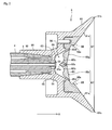
- Fig. 1 is a sectional side view of a rotary atomizing coating machine according to an embodiment of the present invention. Fig. 2 is a sectional side view of a rotary atomizing head according to an embodiment of the present invention. Fig. 3 is a schematic drawing of the route of paint moving on the inner peripheral surface of the rotary atomizing head. Fig. 4 is a schematic drawing of the working state of the rotary atomizing coating machine.
- An entire construction of a rotary atomizing
coating machine 1 having a rotary atomizinghead 6 according to an embodiment of the present invention will be described with reference to Fig. 1. - In addition, in the following description, the direction of an arrow A in Fig. 1 is defined as "the forward direction". The arrow A is substantially in parallel to the axial direction of a later-discussed
rotary shaft 4. - The
coating machine 1 sprays atomized paint to coat a target (for example, a body of a car or a housing of a electric household appliance). For example, as shown in (A), (B) and (C) in Fig. 4, thecoating machine 1 is used while being fixed to a tip part of an articulatedrobot 101, an upper part of a gate-shaped stay 102, or a middle part of astay 103.
"Paint" in this application includes oil paint, water paint and the other kinds of paint widely. - As shown in Fig. 1, the
coating machine 1 mainly comprises amain body 2, amotor 3, therotary shaft 4, thepaint supply tube 5 and a rotary atomizinghead 6. - The
main body 2 is a structural member of thecoating machine 1 and contains themotor 3. Themain body 2 also serves as a support member for fixing thecoating machine 1 to an articulated robot or a stay and supporting thecoating machine 1. An outer peripheral surface of themain body 2 is covered by acover 10 which is a substantially circular cylindrical member. Themain body 2 also contains a high voltage generator (not shown) for electrifying atomized paint sprayed from the rotary atomizinghead 6. - The
motor 3 drives therotary shaft 4. In this embodiment, themotor 3 is a pneumatic motor, which comprises abody part 30, an air bearing 31 and the like. - The
body part 30 is a structural member of themotor 3 and rotatably supports therotary shaft 4 through the air bearing 31. Air is supplied to the air bearing 31 through anair supply passage 31a. - The
rotary shaft 4, which is made of a hollow member, transmits rotary driving force of themotor 3 to the rotary atomizinghead 6. An external thread is formed on a front end part (tip part) of an outer peripheral surface of therotary shaft 4, and an internal thread is formed on an inner peripheral surface of abasal part 60, so as to screw the rotary atomizinghead 6 onto the tip part of therotary shaft 4. - A
turbine 40 comprises blades formed on a rear end part (basal part) of therotary shaft 4 so as to serve as aturbine 40, which is rotated by air from a compressor (not shown) so as to rotate therotary shaft 4. Thepaint supply tube 5 relatively rotatably penetrates therotary shaft 4. - Although the
turbine 40 is formed on the rear end part of therotary shaft 4 in this embodiment, theturbine 40 may alternatively be fixed on therotary shaft 4 as a member separated from theturbine 40. In addition, although therotary shaft 4 is rotated by thepneumatic motor 3 in this embodiment, the present invention is not limited to such a pattern. Therotary shaft 4 may alternatively be rotated by a hydraulic or electric motor. - As shown in Figs. 1 and 2, the
paint supply tube 5 supplies paint to the rotary atomizinghead 6. - In this embodiment, the
paint supply tube 5 is a single tube, which is also used to supply solvent for washing paint adhering to the rotary atomizinghead 6. - The
paint supply tube 5 is a tube serving as asupply passage 50 for passing paint or solvent passes therethrough. Anozzle part 51 is formed at a tip part (front end part) of thepaint supply tube 5. Thenozzle part 51 is formed into a forwardly widened trumpet-shape. - A rear end part of the
paint supply tube 5 is formed into avalve seat 52 and fixedly inserted into a tip part (front end part) of aconnection tube 11. A rear end part of theconnection tube 11 is fixed to themain body 2. - A rod-
like needle valve 12 is inserted into theconnection tube 11 so as to keep a predetermined distance from an inner wall of theconnection tube 11. A tip part (front end part) of theneedle valve 12 is needle-like shaped and can be fitted into thevalve seat 52. Apiston 12a is formed on a basal part (rear end part) of theneedle valve 12 and is biased by aspring 13 so as to fit the tip part of theneedle valve 12 into thevalve seat 52. - A space in front of the
piston 12a is connected to anair supply passage 14. By supplying compressed air to the space, theneedle valve 12 is moved backward against the biasing force of thespring 13, whereby theneedle valve 12 is separated from thevalve seat 52. - A
fluid supply passage 15 bored in themain body 2 is provided to connect containers (not shown), which store paints of various kinds respectively, and a paint switching device (not shown), which selects one of paints and solvent to be supplied to therotary atomizing head 6, to the paint supply tube 5 (more strictly, the rear end part of the connection tube 11). - By operating (longitudinally moving) the
needle valve 12, thefluid supply passage 15 is selectively connected to thepaint supply tube 5 to supply paint or solvent to therotary atomizing head 6, or separated from thepaint supply tube 5 to isolate the supplied paint or solvent from therotary atomizing head 6. - In addition, a control device (not shown) is provided to control the operation of the paint switching device, the power on/off of the
motor 3, the adjustment of rotation speed of themotor 3, and the operation of theneedle valve 12. - Explanation will be given on a detailed construction of the
rotary atomizing head 6 according to Figs. 1 and 2. - The
rotary atomizing head 6 in this embodiment mainly comprises thebasal part 60, a diametrically expandedpart 61, apartition 62 and a blockingmember 65. - The
basal part 60 serving as a rear half of therotary atomizing head 6 is substantially circularly cylindrical. Thebasal part 60 is formed on the inner peripheral surface thereof with the internal thread so as to screw therotary atomizing head 6 onto the tip part of therotary shaft 4. When therotary shaft 4 is rotated, therotary atomizing head 6 is also rotated. - The diametrical expanded
part 61 serving as a front half of therotary atomizing head 6 is formed into a trumpet-shape. Aninner wall surface 61a of the diametrical expandedpart 61 is diametrically expanded from the center the diametrical expandedpart 61 to aperipheral edge 61b. - The
partition 62 is provided at the boundary between the diametrical expandedpart 61 and thebasal part 60. A throughhole 63 is formed in a substantially center portion of thepartition 62. Apaint gallery 64 recessed backward is formed at the peripheral edge of the throughhole 63, that is, on the periphery of thenozzle part 51 of the paint supply tube. - The blocking
member 65 is a substantially discoid member and covers the center of theinner wall surface 61a of the diametrical expandedpart 61. Anatomizing chamber 66 is a space surrounded by the center of theinner wall surface 61a and the blockingmember 65. Paint or solvent is supplied to theatomizing chamber 66 through thepaint supply tube 5. - A substantially
conical projection 65a is formed at the center of the rear surface of the blockingmember 65 which faces theatomizing chamber 66. Arecess 65b is formed at the peripheral edge of theprojection 65a and is depressed forward. Acenter connection hole 65c communicates the middle portion of theprojection 65a with a center of afront surface 65e of the blockingmember 65.Paint supply holes 65d are provided at a boundary between theprojection 65a and the peripheral edge of the blockingmember 65 so as to communicate the inside and the outside of theatomizing chamber 66 with each other along theinner wall surface 61a. Thepaint supply holes 65d supply paint or solvent to a later-discussed innerperipheral surface 67. - The inner
peripheral surface 67 constitutes the front surface of therotary atomizing head 6 and is diametrically expanded from the center of the rotary atomizing head to theperipheral edge 61b. In this embodiment, the innerperipheral surface 67 comprises thefront surface 65e of the blockingmember 65 and the part of theinner wall surface 61a not facing the atomizingchamber 66. - The paint or solvent supplied to the
atomizing chamber 66 through thepaint supply tube 5 is further supplied to the innerperipheral surface 67 through thepaint supply holes 65d. - By rotating the
rotary atomizing head 6, centrifugal force is applied on the paint supplied to the innerperipheral surface 67. The paint moves to theperipheral edge 61b along the innerperipheral surface 67 and is discharged outside atomizingly. - A
step part 68 is formed at the middle portion of the innerperipheral surface 67 between thepaint supply holes 65d and theperipheral edge 61b. Thestep part 68 has a step surface which is substantially perpendicular to the direction of centrifugal force applied on the paint supplied to the inner peripheral surface 67 (the direction substantially perpendicular to the arrow A). - With regard to the
rotary atomizing head 6, which is the embodiment of the rotary atomizing head according to the present invention,
the innerperipheral surface 67 diametrically expanded from the center of the rotary atomizing head to theperipheral edge 61b is formed and centrifugal force generated by the rotation is applied on the paint supplied to the innerperipheral surface 67 so as to discharge the paint outside atomizingly, and
thestep part 68 is formed at the middle portion of the innerperipheral surface 67 between thepaint supply holes 65d, supplying paint or solvent to the innerperipheral surface 67, and theperipheral edge 61b of the innerperipheral surface 67. - With regard to the rotary
atomizing coating machine 1, which is the embodiment of the rotary atomizing coating machine according to the present invention,
the rotary atomizing coating machine has therotary atomizing head 6 constructed so that the innerperipheral surface 67 diametrically expanded from the center of the rotary atomizing head to theperipheral edge 61b which is formed and centrifugal force generated by the rotation is applied on the paint supplied to the innerperipheral surface 67 so as to discharge the paint outside atomizingly, and
thestep part 68 is formed at the middle portion of the innerperipheral surface 67 between thepaint supply holes 65d, supplying paint or solvent to the innerperipheral surface 67, and theperipheral edge 61b of the innerperipheral surface 67. - The construction takes below effects.
- With regard to a conventional rotary atomizing head 106 shown in Fig. 3 (B), any step part is not formed at a middle portion of an inner
peripheral surface 167 betweenpaint supply holes 165d and aperipheral edge 161b of the innerperipheral surface 167. - Accordingly, when the rotary speed of the rotary atomizing head 106 is increased or viscosity of paint is high, paint supplied from the
paint supply holes 165d to the innerperipheral surface 167 is moved within quite shallow parts on lines connecting thepaint supply holes 165d to the corresponding points on theperipheral edge 161b of the innerperipheral surface 167, and is not spread on the inner peripheral surface of the rotary atomizing head 106 uniformly. - Therefore, when the paint is discharged outside atomizingly from the
peripheral edge 161b, the particle size of the paint is not uniform, thereby deteriorating the quality of coating. - When the hardness of pigment included in the paint is high, the specific parts of the inner
peripheral surface 167 on which the paint moves wear out. As a result, it is difficult to lengthen the life of the rotary atomizing head 106. For preventing the wearing of the specific parts, it is necessary to construct the rotary atomizing head 106 by hardwearing material such as ceramic or titanium or to form a plating layer with hard material on the corresponding parts of the innerperipheral surface 167. Therefore, it is difficult to produce the rotary atomizing head 106 cheaply. - Furthermore, since paint moves on the specific parts of the inner
peripheral surface 167, the amount of wearing of the rotary atomizing head 106 per operating time is increased, whereby the paint may be contaminated with wearing powder so as to cause the failure of paint. - To the contrary, with regard to the
rotary atomizing head 6 of this embodiment shown in Fig. 3 (A), thestep part 68 is formed at the middle portion of the innerperipheral surface 67 between thepaint supply holes 65d and theperipheral edge 61b of the innerperipheral surface 67. - Accordingly, even if the rotary speed of the
rotary atomizing head 6 is increased or viscosity of paint is high, paint supplied from thepaint supply holes 65d to the innerperipheral surface 67 is dammed up once by thestep part 68 and spread on thestep part 68 uniformly in the middle of the movement, and then gets over thestep part 68 and moves to theperipheral edge 61b. - As a result, the paint moving within the part of the inner
peripheral surface 67 between thepaint supply holes 65d and theperipheral edge 61b is spread on the whole part thinly. Accordingly, when the paint is discharged outside atomizingly from theperipheral edge 61b, the particle size of the paint is uniform, thereby improving the quality of coating. - Even if the hardness of pigment included in the paint is high, the paint moves spreadingly uniformly on the inner
peripheral surface 67 so as to prevent the specific parts of the innerperipheral surface 67 on which the paint moves from wearing out, thereby lengthening the life of therotary atomizing head 6. Collaterally with it, it is not necessary to construct therotary atomizing head 6 by hardwearing material such as ceramic or titanium or to form a plating layer with hard material on the corresponding parts of the innerperipheral surface 67 so as to prevent the wearing of the specific parts, whereby therotary atomizing head 6 can be produced cheaply. - Furthermore, since the paint moves spreadingly uniformly on the inner
peripheral surface 67, the amount of wearing of therotary atomizing head 6 per operating time is reduced, whereby the paint is prevented from being contaminated with wearing powder so as to cause the failure of paint. - In addition, a
step surface 68a of thestep part 68 is preferably substantially perpendicular to the direction of centrifugal force applied on the paint supplied to the innerperipheral surface 67. According to this, paint is certainly dammed up once so as to spread the paint on the innerperipheral surface 67 uniformly. - For preventing wearing of the inner
peripheral surface 67, thestep part 68 is preferably provided near thepaint supply holes 65d in the middle portion of the innerperipheral surface 67 between thepaint supply holes 65d and theperipheral edge 61b of the innerperipheral surface 67. - Two or more step parts may be provided in the middle portion of the inner peripheral surface between the paint supply holes and the peripheral edge of the inner peripheral surface.
- The present invention can be used for a rotary atomizing head or a rotary atomizing coating machine having a rotary atomizing head.
Claims (4)
- A rotary atomizing head that an inner peripheral surface diametrically expanded from a center of the rotary atomizing head to a peripheral edge is formed and centrifugal force generated by rotation is applied on paint supplied to the inner peripheral surface so as to discharge the paint outside atomizingly, characterized in that:a step part is formed at a middle portion of the inner peripheral surface between paint supply holes, supplying paint to the inner peripheral surface, and the peripheral edge of the inner peripheral surface.
- The rotary atomizing head as set forth in claim 1, wherein the step part comprises a step surface preferably substantially perpendicular to a direction of centrifugal force applied on the paint supplied to the inner peripheral surface.
- A rotary atomizing coating machine comprising a rotary atomizing head that an inner peripheral surface diametrically expanded from a center of the rotary atomizing head to a peripheral edge is formed and centrifugal force generated by rotation is applied on paint supplied to the inner peripheral surface so as to discharge the paint outside atomizingly,
characterized in that:a step part is formed at a middle portion of the inner peripheral surface between paint supply holes, supplying paint to the inner peripheral surface, and the peripheral edge of the inner peripheral surface. - The rotary atomizing coating machine as set forth in claim 3, wherein the step part comprises a step surface preferably substantially perpendicular to a direction of centrifugal force applied on the paint supplied to the inner peripheral surface.
Applications Claiming Priority (2)
| Application Number | Priority Date | Filing Date | Title |
|---|---|---|---|
| JP2004323059A JP4554334B2 (en) | 2004-11-08 | 2004-11-08 | Rotary atomizing head and rotary atomizing coating equipment |
| PCT/JP2005/020767 WO2006049341A1 (en) | 2004-11-08 | 2005-11-07 | Rotary atomizing head and rotary atomizing coating device |
Publications (3)
| Publication Number | Publication Date |
|---|---|
| EP1825921A1 true EP1825921A1 (en) | 2007-08-29 |
| EP1825921A4 EP1825921A4 (en) | 2008-10-22 |
| EP1825921B1 EP1825921B1 (en) | 2012-10-03 |
Family
ID=36319328
Family Applications (1)
| Application Number | Title | Priority Date | Filing Date |
|---|---|---|---|
| EP05803278A Ceased EP1825921B1 (en) | 2004-11-08 | 2005-11-07 | Rotary atomizing head and rotary atomizing coating device |
Country Status (6)
| Country | Link |
|---|---|
| US (1) | US7726586B2 (en) |
| EP (1) | EP1825921B1 (en) |
| JP (1) | JP4554334B2 (en) |
| CN (1) | CN101056713B (en) |
| CA (1) | CA2586020C (en) |
| WO (1) | WO2006049341A1 (en) |
Cited By (2)
| Publication number | Priority date | Publication date | Assignee | Title |
|---|---|---|---|---|
| US8720797B2 (en) | 2007-05-24 | 2014-05-13 | Toyota Jidosha Kabushiki Kaisha | Rotary atomizing head, rotary atomization coating apparatus, and rotary atomization coating method |
| KR101764676B1 (en) | 2015-09-14 | 2017-08-03 | (주)에스시아이 | revolving spray nozzle for painting and painting method of pipe |
Families Citing this family (18)
| Publication number | Priority date | Publication date | Assignee | Title |
|---|---|---|---|---|
| JP4554334B2 (en) * | 2004-11-08 | 2010-09-29 | トヨタ自動車株式会社 | Rotary atomizing head and rotary atomizing coating equipment |
| JP4750803B2 (en) * | 2006-01-19 | 2011-08-17 | Abb株式会社 | Rotary atomizing head type coating equipment |
| DE102006022057B3 (en) | 2006-05-11 | 2007-10-31 | Dürr Systems GmbH | Rotary atomizer`s application unit for use in varnishing machine, has surface layer, on which thin coating medium with specific film thickness is formed, where layer reduces boundary surface friction between medium and overflow surface |
| JP4584291B2 (en) * | 2007-07-26 | 2010-11-17 | トヨタ自動車株式会社 | Rotating atomizing electrostatic coating machine and rotating atomizing coating method |
| JP4584283B2 (en) * | 2007-05-24 | 2010-11-17 | トヨタ自動車株式会社 | Rotary atomizing head and rotary atomizing coating equipment |
| FR2917309B1 (en) * | 2007-06-13 | 2013-10-25 | Sames Technologies | ROTATING PROJECTOR OF COATING PRODUCT AND INSTALLATION COMPRISING SUCH A PROJECTOR. |
| JP2009034577A (en) * | 2007-07-31 | 2009-02-19 | Toyota Motor Corp | Cleaning method of rotary atomizing electrostatic coating machine |
| US20090206182A1 (en) * | 2008-01-25 | 2009-08-20 | Abb Inc. | Rotary Atomizer with an Improved Valve |
| US10155233B2 (en) * | 2008-04-09 | 2018-12-18 | Carlisle Fluid Technologies, Inc. | Splash plate retention method and apparatus |
| JP4494498B2 (en) * | 2008-06-12 | 2010-06-30 | トヨタ自動車株式会社 | Rotating atomizing head, rotating atomizing coating apparatus and rotating atomizing coating method |
| EP2537593B1 (en) * | 2010-01-06 | 2015-03-11 | Ransburg Industrial Finishing KK | Rotary atomizing head for electrostatic coating machine |
| RU2472590C2 (en) * | 2010-12-03 | 2013-01-20 | Федеральное государственное образовательное учреждение высшего профессионального образования "Ижевская государственная сельскохозяйственная академия" | Centrifugal aerosol electric generator |
| WO2015114924A1 (en) * | 2014-01-29 | 2015-08-06 | 本田技研工業株式会社 | Rotary atomizing coating device and spray head |
| JP6314735B2 (en) * | 2014-08-07 | 2018-04-25 | 日産自動車株式会社 | Bell cup of rotary atomizing coating equipment |
| KR101532592B1 (en) * | 2014-11-03 | 2015-07-01 | (주)태송 | Spray nozzle for fire-extinguishing |
| JP6454792B2 (en) * | 2015-09-17 | 2019-01-16 | 本田技研工業株式会社 | Rotating atomizing coating device and spray head |
| KR101634298B1 (en) * | 2016-01-20 | 2016-06-30 | 박상은 | Doule bell-cup |
| US11331681B2 (en) | 2018-08-07 | 2022-05-17 | Carlisle Fluid Technologies, Inc. | Fluid tip for spray applicator |
Family Cites Families (26)
| Publication number | Priority date | Publication date | Assignee | Title |
|---|---|---|---|---|
| IL55501A0 (en) * | 1977-09-14 | 1978-12-17 | Bals Edward Julius | Ratary atomiser |
| JPS56141867A (en) * | 1980-04-04 | 1981-11-05 | Toyota Motor Corp | Rotary atomizing electrostatic coating device |
| JPS5742361A (en) * | 1980-08-26 | 1982-03-09 | Nippon Ranzubaagu Kk | Rotary atomizing head for sprayer |
| DE3040136A1 (en) * | 1980-10-24 | 1982-06-03 | Hermann Behr & Sohn Gmbh & Co, 7121 Ingersheim | SPRAYER |
| JPS57174170A (en) * | 1981-04-20 | 1982-10-26 | Nippon Ranzubaagu Kk | Rotary atomizing head of sprayer |
| FR2563835B1 (en) * | 1984-05-02 | 1986-12-12 | Saint Gobain Vitrage | PROCESS AND DEVICE FOR MANUFACTURING A LAYER OF PLASTIC MATERIAL OF HIGH OPTICAL QUALITY AND SHEET OBTAINED BY THIS PROCESS |
| US4684064A (en) * | 1985-08-19 | 1987-08-04 | Graco Inc. | Centrifugal atomizer |
| US4919333A (en) * | 1986-06-26 | 1990-04-24 | The Devilbiss Company | Rotary paint atomizing device |
| JPS63229163A (en) * | 1987-03-19 | 1988-09-26 | Toyota Motor Corp | Spray head of rotary atomizing electrostatic painting |
| JP2600390B2 (en) | 1989-09-13 | 1997-04-16 | トヨタ自動車株式会社 | Rotary atomizing coating equipment |
| US5078321A (en) * | 1990-06-22 | 1992-01-07 | Nordson Corporation | Rotary atomizer cup |
| US5152458A (en) * | 1991-06-13 | 1992-10-06 | Curtis Harold D | Automatically adjustable fluid distributor |
| JP3166113B2 (en) * | 1993-03-26 | 2001-05-14 | エービービー株式会社 | Rotary atomizing electrostatic coating machine |
| JPH0824719A (en) * | 1994-07-14 | 1996-01-30 | Nissan Motor Co Ltd | Rotating atomizing electrostatic coating device |
| JPH0833859A (en) * | 1994-07-22 | 1996-02-06 | Nissan Motor Co Ltd | Rotating atomizing electrostatic coating device |
| JP3473718B2 (en) * | 1994-07-22 | 2003-12-08 | 日産自動車株式会社 | Rotary atomization electrostatic coating method and apparatus |
| JPH08173857A (en) * | 1994-12-27 | 1996-07-09 | Trinity Ind Corp | Electrostatic coating apparatus |
| US5934574A (en) * | 1995-12-05 | 1999-08-10 | Van Der Steur; Gunnar | Rotary atomizer |
| JP2809170B2 (en) * | 1996-01-19 | 1998-10-08 | トヨタ自動車株式会社 | Rotary atomizing electrostatic coating equipment |
| JPH09220498A (en) | 1996-02-14 | 1997-08-26 | Toyota Motor Corp | Rotary atomizing electrostatic coating equipment |
| JP3726329B2 (en) * | 1996-02-16 | 2005-12-14 | トヨタ自動車株式会社 | Bell head of rotary atomizing electrostatic coating machine and rotary atomizing electrostatic coating machine |
| JP3178654B2 (en) * | 1996-12-03 | 2001-06-25 | エービービー株式会社 | Rotary atomizing head type coating equipment |
| US6322011B1 (en) * | 2000-03-14 | 2001-11-27 | Illinois Tool Works Inc. | Electrostatic coating system and dual lip bell cup therefor |
| JP4729183B2 (en) * | 2001-03-01 | 2011-07-20 | 旭サナック株式会社 | Painting gun |
| CA2567143A1 (en) * | 2004-05-25 | 2005-12-08 | Trinity Industrial Corporation | Coating machine and rotary atomizing head thereof |
| JP4554334B2 (en) * | 2004-11-08 | 2010-09-29 | トヨタ自動車株式会社 | Rotary atomizing head and rotary atomizing coating equipment |
-
2004
- 2004-11-08 JP JP2004323059A patent/JP4554334B2/en not_active Expired - Lifetime
-
2005
- 2005-11-07 EP EP05803278A patent/EP1825921B1/en not_active Ceased
- 2005-11-07 WO PCT/JP2005/020767 patent/WO2006049341A1/en not_active Ceased
- 2005-11-07 CN CN2005800380993A patent/CN101056713B/en not_active Expired - Fee Related
- 2005-11-07 CA CA2586020A patent/CA2586020C/en not_active Expired - Lifetime
- 2005-11-07 US US11/666,423 patent/US7726586B2/en not_active Expired - Lifetime
Cited By (2)
| Publication number | Priority date | Publication date | Assignee | Title |
|---|---|---|---|---|
| US8720797B2 (en) | 2007-05-24 | 2014-05-13 | Toyota Jidosha Kabushiki Kaisha | Rotary atomizing head, rotary atomization coating apparatus, and rotary atomization coating method |
| KR101764676B1 (en) | 2015-09-14 | 2017-08-03 | (주)에스시아이 | revolving spray nozzle for painting and painting method of pipe |
Also Published As
| Publication number | Publication date |
|---|---|
| CA2586020A1 (en) | 2006-05-11 |
| CA2586020C (en) | 2012-03-06 |
| US20070290081A1 (en) | 2007-12-20 |
| JP2006130423A (en) | 2006-05-25 |
| WO2006049341A1 (en) | 2006-05-11 |
| EP1825921B1 (en) | 2012-10-03 |
| CN101056713B (en) | 2011-06-15 |
| EP1825921A4 (en) | 2008-10-22 |
| US7726586B2 (en) | 2010-06-01 |
| CN101056713A (en) | 2007-10-17 |
| JP4554334B2 (en) | 2010-09-29 |
Similar Documents
| Publication | Publication Date | Title |
|---|---|---|
| CA2586020C (en) | Rotary atomizing head and rotary atomizing coating machine | |
| EP1514605B1 (en) | Rotary atomizer and coating method by it | |
| US9687863B2 (en) | Rotary atomizing head type coating machine | |
| EP1911522B1 (en) | Electrostatic coating apparatus | |
| US8973848B2 (en) | Composite air bearing assembly | |
| US11213838B2 (en) | Rotary atomizing head type coating machine | |
| CA2988061C (en) | Painting device | |
| CN109590120B (en) | coating device | |
| JP5378238B2 (en) | Painting equipment | |
| JP2020522385A (en) | Rotary atomizer bell cup | |
| GB2367772A (en) | Two-package-mixing discharging device and two-package-mixing coating device | |
| JP6179002B2 (en) | Rotary atomizing head type coating machine | |
| WO2005115636A1 (en) | Method for controlling spray pattern of rotary atomizing head type coating device and rotary atomizing head type coating device | |
| JP5736273B2 (en) | Coating method and coating apparatus | |
| JP2009034577A (en) | Cleaning method of rotary atomizing electrostatic coating machine | |
| JPH11128779A (en) | Spray gun for rotary atomization type coating | |
| GB2193447A (en) | Electrostatic spray coating apparatus | |
| KR100671088B1 (en) | Swivel device for sealer application | |
| JP2011041893A (en) | Rotary atomization type coating device | |
| JPH0113570Y2 (en) | ||
| JPH04334565A (en) | Rotary atomization head-type electrostatic coating device | |
| JP2015217346A (en) | Coating machine and coating method |
Legal Events
| Date | Code | Title | Description |
|---|---|---|---|
| PUAI | Public reference made under article 153(3) epc to a published international application that has entered the european phase |
Free format text: ORIGINAL CODE: 0009012 |
|
| 17P | Request for examination filed |
Effective date: 20070507 |
|
| AK | Designated contracting states |
Kind code of ref document: A1 Designated state(s): DE FR GB |
|
| DAX | Request for extension of the european patent (deleted) | ||
| A4 | Supplementary search report drawn up and despatched |
Effective date: 20080922 |
|
| 17Q | First examination report despatched |
Effective date: 20090603 |
|
| RBV | Designated contracting states (corrected) |
Designated state(s): DE FR GB |
|
| GRAP | Despatch of communication of intention to grant a patent |
Free format text: ORIGINAL CODE: EPIDOSNIGR1 |
|
| RAP1 | Party data changed (applicant data changed or rights of an application transferred) |
Owner name: TOYOTA JIDOSHA KABUSHIKI KAISHA Owner name: TRINITY INDUSTRIAL CORP. |
|
| GRAS | Grant fee paid |
Free format text: ORIGINAL CODE: EPIDOSNIGR3 |
|
| GRAA | (expected) grant |
Free format text: ORIGINAL CODE: 0009210 |
|
| RIN1 | Information on inventor provided before grant (corrected) |
Inventor name: ICHIMURA, MAKOTO Inventor name: MURAI, MASARU, C/O TOYOTA JIDOSHA KABUSHIKI KAISHA |
|
| AK | Designated contracting states |
Kind code of ref document: B1 Designated state(s): DE FR GB |
|
| REG | Reference to a national code |
Ref country code: GB Ref legal event code: FG4D |
|
| REG | Reference to a national code |
Ref country code: DE Ref legal event code: R096 Ref document number: 602005036427 Country of ref document: DE Effective date: 20121129 |
|
| RAP2 | Party data changed (patent owner data changed or rights of a patent transferred) |
Owner name: TRINITY INDUSTRIAL CORP. Owner name: TOYOTA JIDOSHA KABUSHIKI KAISHA |
|
| PLBE | No opposition filed within time limit |
Free format text: ORIGINAL CODE: 0009261 |
|
| STAA | Information on the status of an ep patent application or granted ep patent |
Free format text: STATUS: NO OPPOSITION FILED WITHIN TIME LIMIT |
|
| 26N | No opposition filed |
Effective date: 20130704 |
|
| REG | Reference to a national code |
Ref country code: DE Ref legal event code: R097 Ref document number: 602005036427 Country of ref document: DE Effective date: 20130704 |
|
| REG | Reference to a national code |
Ref country code: FR Ref legal event code: PLFP Year of fee payment: 11 |
|
| REG | Reference to a national code |
Ref country code: FR Ref legal event code: PLFP Year of fee payment: 12 |
|
| REG | Reference to a national code |
Ref country code: FR Ref legal event code: PLFP Year of fee payment: 13 |
|
| REG | Reference to a national code |
Ref country code: FR Ref legal event code: PLFP Year of fee payment: 14 |
|
| PGFP | Annual fee paid to national office [announced via postgrant information from national office to epo] |
Ref country code: GB Payment date: 20230928 Year of fee payment: 19 |
|
| PGFP | Annual fee paid to national office [announced via postgrant information from national office to epo] |
Ref country code: FR Payment date: 20230929 Year of fee payment: 19 |
|
| PGFP | Annual fee paid to national office [announced via postgrant information from national office to epo] |
Ref country code: DE Payment date: 20230929 Year of fee payment: 19 |
|
| REG | Reference to a national code |
Ref country code: DE Ref legal event code: R119 Ref document number: 602005036427 Country of ref document: DE |
|
| GBPC | Gb: european patent ceased through non-payment of renewal fee |
Effective date: 20241107 |
|
| PG25 | Lapsed in a contracting state [announced via postgrant information from national office to epo] |
Ref country code: DE Free format text: LAPSE BECAUSE OF NON-PAYMENT OF DUE FEES Effective date: 20250603 |
|
| PG25 | Lapsed in a contracting state [announced via postgrant information from national office to epo] |
Ref country code: GB Free format text: LAPSE BECAUSE OF NON-PAYMENT OF DUE FEES Effective date: 20241107 |
|
| PG25 | Lapsed in a contracting state [announced via postgrant information from national office to epo] |
Ref country code: FR Free format text: LAPSE BECAUSE OF NON-PAYMENT OF DUE FEES Effective date: 20241130 |