EP1825895B1 - Game apparatus and storage medium storing game program - Google Patents
Game apparatus and storage medium storing game program Download PDFInfo
- Publication number
- EP1825895B1 EP1825895B1 EP06113173.6A EP06113173A EP1825895B1 EP 1825895 B1 EP1825895 B1 EP 1825895B1 EP 06113173 A EP06113173 A EP 06113173A EP 1825895 B1 EP1825895 B1 EP 1825895B1
- Authority
- EP
- European Patent Office
- Prior art keywords
- data
- viewpoint
- game
- contact detection
- player character
- Prior art date
- Legal status (The legal status is an assumption and is not a legal conclusion. Google has not performed a legal analysis and makes no representation as to the accuracy of the status listed.)
- Active
Links
Images


Classifications
-
- A—HUMAN NECESSITIES
- A63—SPORTS; GAMES; AMUSEMENTS
- A63F—CARD, BOARD, OR ROULETTE GAMES; INDOOR GAMES USING SMALL MOVING PLAYING BODIES; VIDEO GAMES; GAMES NOT OTHERWISE PROVIDED FOR
- A63F13/00—Video games, i.e. games using an electronically generated display having two or more dimensions
- A63F13/55—Controlling game characters or game objects based on the game progress
- A63F13/57—Simulating properties, behaviour or motion of objects in the game world, e.g. computing tyre load in a car race game
- A63F13/577—Simulating properties, behaviour or motion of objects in the game world, e.g. computing tyre load in a car race game using determination of contact between game characters or objects, e.g. to avoid collision between virtual racing cars
-
- A—HUMAN NECESSITIES
- A63—SPORTS; GAMES; AMUSEMENTS
- A63F—CARD, BOARD, OR ROULETTE GAMES; INDOOR GAMES USING SMALL MOVING PLAYING BODIES; VIDEO GAMES; GAMES NOT OTHERWISE PROVIDED FOR
- A63F13/00—Video games, i.e. games using an electronically generated display having two or more dimensions
- A63F13/50—Controlling the output signals based on the game progress
- A63F13/52—Controlling the output signals based on the game progress involving aspects of the displayed game scene
- A63F13/525—Changing parameters of virtual cameras
-
- A—HUMAN NECESSITIES
- A63—SPORTS; GAMES; AMUSEMENTS
- A63F—CARD, BOARD, OR ROULETTE GAMES; INDOOR GAMES USING SMALL MOVING PLAYING BODIES; VIDEO GAMES; GAMES NOT OTHERWISE PROVIDED FOR
- A63F2300/00—Features of games using an electronically generated display having two or more dimensions, e.g. on a television screen, showing representations related to the game
- A63F2300/60—Methods for processing data by generating or executing the game program
- A63F2300/64—Methods for processing data by generating or executing the game program for computing dynamical parameters of game objects, e.g. motion determination or computation of frictional forces for a virtual car
- A63F2300/643—Methods for processing data by generating or executing the game program for computing dynamical parameters of game objects, e.g. motion determination or computation of frictional forces for a virtual car by determining the impact between objects, e.g. collision detection
-
- A—HUMAN NECESSITIES
- A63—SPORTS; GAMES; AMUSEMENTS
- A63F—CARD, BOARD, OR ROULETTE GAMES; INDOOR GAMES USING SMALL MOVING PLAYING BODIES; VIDEO GAMES; GAMES NOT OTHERWISE PROVIDED FOR
- A63F2300/00—Features of games using an electronically generated display having two or more dimensions, e.g. on a television screen, showing representations related to the game
- A63F2300/60—Methods for processing data by generating or executing the game program
- A63F2300/66—Methods for processing data by generating or executing the game program for rendering three dimensional images
- A63F2300/6661—Methods for processing data by generating or executing the game program for rendering three dimensional images for changing the position of the virtual camera
- A63F2300/6676—Methods for processing data by generating or executing the game program for rendering three dimensional images for changing the position of the virtual camera by dedicated player input
Definitions
- the present invention relates to a game apparatus and a storage medium storing game program. More specifically, the present invention relates to a game apparatus which has an operating means with which a player performs an operation input, a display means for displaying a game image, and storage means for storing in advance data to generate at least a virtual three-dimensional space, and a storage medium storing game program.
- a further example of the related art is US 6,050,896 .
- a three-dimensional game space is transformed into a two-dimensional projection viewpoint and the judgment of a collision is based on the positions of display objects in the two-dimensional projection.
- Another related art is US 6,128,018 , which discloses collision detections in the three-dimensional space.
- the three-dimensional game is disclosed in the Super Mario 64 Otasuke Guide
- the two-dimensional game is disclosed in the Super Mario Brothers Urawaza Taizensyu. It is a common recognition that the two-dimensional game is developed into the three-dimensional game.
- the respective games have a specific amusement, and cannot be compared with each other. However, there is no game for pursuing a further enjoyment of the game by combining the respective properties.
- Another object of the present invention is to provide a game apparatus and a storage medium storing game program which can increase interest of the game by utilizing properties of a two-dimensional game and of a three-dimensional game.
- the other object of the present invention is to provide a game apparatus and a storage medium storing game program capable of enjoying playing a two-dimensional game by utilizing a three-dimensional game space.
- the present invention employs following a configuration in order to solve the above-described problems. It should be noted that reference numerals and supplement inside the parentheses show one example of a corresponding relationship with the embodiments described later for easy understanding of the present invention, and does not limit the present invention.
- a game apparatus has an operating means with which a player makes an operation input, a display means for displaying a game image, and a storage means for storing in advance data for generating at least a virtual three-dimensional space.
- the game apparatus includes an input detecting means, a player character controlling means, an object controlling means, a contact detection means, a viewpoint controlling means, and a viewpoint switching means.
- the input detecting means detects input data corresponding to an operation input from the operating means, and temporarily stores it in the storage means.
- the player character controlling means arranges a player character to be operated by the player in the virtual three-dimensional space by utilizing player character data stored in the storage means in response to first input data temporarily stored by the input detecting means.
- the object controlling means arranges an object not to be operated by the player in the virtual three-dimensional space by utilizing object data stored in the storage means.
- the contact detection means determines whether or not the player character and a predetermined object are contacted with each other.
- the viewpoint controlling means controls a viewpoint in the virtual three-dimensional space.
- the viewpoint switching means switches the viewpoint depending on second input data temporarily stored by the input detecting means.
- the contact detection means changes contact detection data set to the predetermined object depending on a switching result of the viewpoint switching means.
- a game system (12) has an operating means (22, 26) with which a player makes an operation input, a display means (34) for displaying a game image, and a storage means (40) for storing in advance data for generating at least a virtual three-dimensional space.
- the game apparatus further includes an input detecting means (36, S51), a player character controlling means (36, S5), an object controlling means (36, S7), contact detection means (36, S9), a viewpoint controlling means (36, S3), and a viewpoint switching means (36, S21, S23, S29).
- the input detecting means detects input data corresponding to an operation input from the operating means, and temporarily stores it in the storage means.
- the player character controlling means arranges a player character to be operated by the player in the virtual three-dimensional space by utilizing player character data (404c) stored in the storage means in response to first input data temporarily stored by the input detecting means. For example, the player character is moved in response to an operation input from the operating means within the virtual three-dimensional space.
- the object controlling means arranges an object not to be operated by the player in the virtual three-dimensional space by utilizing object data (404d) stored in the storage means.
- a computer or a processor (36) causes an enemy object to appear, move independent of player's operation according to a program, and arrange (generate) an item object and a background object (104,106,108).
- the contact detection means determines whether or not the player character and a predetermined object are contacted with each other.
- the viewpoint controlling means controls a viewpoint (virtual camera) in the virtual three-dimensional space. For example, a position of the viewpoint is updated according to the movement of the player character.
- the viewpoint switching means switches the viewpoint depending on second input data temporarily stored by the input detecting means. For example, according to an instruction of switching the viewpoint by the player, the position and the direction of the viewpoint are switched.
- the contact detection means changes the contact detection data set used for contact detection between said player character and said predetermined object depending on a switching result of the viewpoint switching means.
- the viewpoint switching means (36, S21, S23, S29) is adapted to switch the viewpoint between a three-dimensional game screen (200) and a two-dimensional game screen (100).
- a contact detection is executed by utilizing contact detection data depending on the viewpoint, so that a player can enjoy playing a game by viewing a different game screen depending on the viewpoint.
- the contact detection data includes first detection data for performing a contact detection on all three dimensions of the virtual three-dimensional space and second detection data for performing a contact detection on one dimension or a combination of any two dimensions of the virtual three-dimensional space, and the contact detection means selects any one of the first detection data and the second detection data depending on a switching result of the viewpoint switching means.
- the contact detection data includes first detection data (404i) for performing a contact detection on all three dimensions of the virtual three-dimensional space and second detection data (404j) for performing a contact detection on one dimension or a combination of any two dimensions of the virtual three-dimensional space.
- the first detection data is data for performing a contact detection in an x-axis direction, a y-axis direction, and a z-axis direction within a virtual three-dimensional space.
- the second detection data is data for performing a contact detection within the virtual three-dimensional space in one or a combination of any two of the x-axis direction, the y-axis direction, and the z-axis direction (x-axis direction and y-axis direction, y-axis direction and z-axis direction, and z-axis direction and x-axis direction).
- the contact detection means selects any one of the first detection data and the second detection data depending on a switching result of the viewpoint switching means.
- the game apparatus further includes a mode switching means for switching between a first mode for switching to a view of all three dimensions of the virtual three-dimensional space by the viewpoint switching means and a second mode for switching to a view by combining one dimension or a combination of any two dimensions of the virtual three-dimensional space by the viewpoint switching means.
- the contact detection means selects the first detection data when the mode switching means switches to the first mode, and the contact detection means selects the second detection data when the mode switching means switches to the second mode.
- the game apparatus further includes a mode switching means (36, S55, S59, S61, S63).
- the mode switching means switches between a first mode for switching to a view of all three dimensions of the virtual three-dimensional space by the viewpoint switching means and a second mode for switching to a view by combining one dimension or a combination of any two dimensions of the virtual three-dimensional space by the viewpoint switching means. Accordingly, in the first mode, a switching of the viewpoint is performed on all of the x-axis direction, the y-axis direction, and the z-axis direction.
- the contact detection means selects the first detection data when the mode switching means switches to the first mode, and the contact detection means selects the second detection data when the mode switching means switches to the second mode.
- the viewpoint can thus be switched, so that a player can enjoy playing a game while viewing a different game screen depending on the viewpoint. For example, it is possible to play a game by displaying the game screen of the three-dimensional game in a two-dimensional manner.
- a storage medium storing game program stores a game program of a game apparatus having an operating means with which a player makes an operation input, a display means for displaying a game image, and a storage means for storing in advance data for generating at least a virtual three-dimensional space.
- the game program makes a processor of the game apparatus function as an input detecting means, a player character controlling means, an object controlling means, a contact detection means, a viewpoint controlling means, and a viewpoint switching means.
- the input detecting means detects input data corresponding to an operation input from the operating means, and temporarily stores it in the storage means.
- the player character controlling means arranges a player character to be operated by the player in the virtual three-dimensional space by utilizing the player character data stored in the storage means in response to first input data temporarily stored in the input detecting means.
- the object controlling means arranges an object not to be operated by the player in the virtual three-dimensional space by utilizing the object data stored in the storage means.
- the contact detection means determines whether or not the player character and the predetermined object are contacted with each other.
- the viewpoint controlling means controls a viewpoint in the virtual three-dimensional space.
- the viewpoint switching means switches the viewpoint depending on second input data temporarily stored by the input detecting means.
- the contact detection means changes the data set used for contact detection between said player character and said predetermined object depending on a switching result of said viewpoint switching means.
- the contact detection data includes first detection data for performing a contact detection on all three dimensions of the virtual three-dimensional space and second detection date for performing a contact detection in one dimension or a combination of any two dimensions of the virtual three-dimensional space.
- the contact detection means selects any one of said first detection data and said second detection data depending on a switching result of said viewpoint switching means.
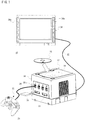
- a video game system 10 of one embodiment of the present invention includes a video game apparatus 12.
- the video game apparatus 12 includes an approximately cubic housing 14, and the housing 14 is provided with an optical disk drive 16 on an upper surface thereof.
- An optical disk 18 which is one example of an information storage medium storing a game program, and the like is mounted on the optical disk drive 16.
- the housing 14 is provided with a plurality of connectors 20 (four in this embodiment) on a front surface thereof These connectors 20 are for connecting a controller 22 to the video game apparatus 12 by a cable 24, and can connect up to four controllers to the video game apparatus 12 in this embodiment.
- the controller 22 is provided with an operating portion (operating switch) 26 on upper, lower, lateral sides and etc. thereof.
- the operating portion 26, for example, includes two analog joysticks, one cross switch, a plurality of button switches, and so on.
- One analog joystick is utilized for inputting a moving direction and/or a moving speed, moving amount and etc. of a player character (a moving image character object, operable with the controller 22 by a player) according to an amount and a direction of an inclination of the stick.
- the other analog joystick is utilized for controlling a movement of the virtual camera according to a direction of an inclination thereof.
- the cross switch is utilized for instructing a moving direction of the player character in place of the analog joystick.
- the button switches are utilized for instructing a movement of the player character, switching a point of view of the virtual camera in the three-dimensional image, adjusting the moving speed of the player character and etc.
- the button switches for example, further control a menu selection and a movement of a pointer or a cursor.
- the controller 22 is connected to the video game apparatus 12 by the cable 24 integrated into the controller 22 in this embodiment.
- the controller 22 may be connected to the video game apparatus 12 by another method such as a wireless manner via an electromagnetic wave (radio wave, infrared ray, for example).
- a detailed structure of the operating portion 26 of the controller 22 is, of course, not limited to the structure of the embodiment, and can be arbitrarily changed or modified.
- the only one analog joystick may be utilized, or no analog joystick may be utilized.
- the cross switch may not be utilized.
- At least one or plurality of (two in this embodiment) memory slots 28 are provided below the connectors 20 on the front surface of the housing 14 of the video game apparatus 12.
- a memory card 30 is inserted to this memory slot 28.
- the memory card 30 is utilized for loading the game program, etc. read from the optical disk 18 so as to temporarily store it, or saving game data of the game (result data or progress data of the game) that the player plays by utilizing the game system 10.
- the housing 14 of the video game apparatus 12 is provided with an AV cable connector (not shown) on its rear surface.
- the connector allows a monitor 34 to be connected to the video game apparatus 12 over an AV cable 32.
- the monitor 34 is typically a color television receiver, and the AV cable 32 inputs a video signal from the video game apparatus 12 to a video input terminal of the color television and inputs a sound signal to a sound input terminal. Accordingly, a game image of a three-dimension (3D) video game, for example, is displayed on the color television (monitor) 34, and a game sound (stereo game sound) such as a game music, a sound effect, etc. is output from right and left speakers 34a.
- 3D three-dimension
- a user or a game player first turns on an electric power source of the video game apparatus 12 in order to play a game (or another application), and then selects a suitable optical disk 18 storing a video game (or another application the play wants to play), and loads the optical disk 18 on the disk drive 16 of the video game apparatus 12.
- the video game apparatus 12 starts to execute the video game or another application on the basis of software stored in the optical disk 18.
- the player operates the controller 22 so as to apply an input to the video game apparatus 12.
- the player starts the game or another application by operating any one of the operating portion 26.
- By moving another of the operating portion 26, it is possible to move the moving image object (player character) in different directions and to change a viewpoint of the user (camera position) in the three-dimensional (3D) game world.
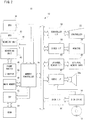
- FIG 2 is a block diagram showing an electric configuration of the video game system 10 of Figure 1 embodiment.
- the video game apparatus 12 is provided with a central processing unit (hereinafter, may be referred to as "CPU") 36.
- the CPU 36 is called a computer or a processor, and is in charge of governing overall control of the video game apparatus 12.
- the CPU 36 or the computer functions as a game processor and is connected with a memory controller 38 via a bus.
- the memory controller 38 mainly controls writing to and reading from a main memory 40 connected via a bus under control of the CPU 36.
- the memory controller 38 is connected with a GPU (Graphics Processing Unit) 42.
- GPU Graphics Processing Unit
- the GPU 42 forms a part of a rendering means, and is constructed by a single chip ASIC, for example.
- the GPU 42 receives a graphics command from the CPU 36 via the memory controller 38, and, in response to the command, generates the three-dimensional (3D) game image by a geometry unit 44 and a rendering unit 46.
- the geometry unit 44 performs a coordinate operation process such as turn-around or rotation, movement, transformation, etc. of a variety of objects and objects (which is formed by a plurality of polygons, and the polygon is a polygonal plane defined by at least three vertex coordinates) in a three-dimension coordinates system.
- the rendering unit 46 performs an image generating process such as pasting a texture on each of polygons of the variety of objects, and so on.
- image generating process such as pasting a texture on each of polygons of the variety of objects, and so on.
- three-dimension image data to be displayed on the game screen is created by the GPU 42, and the image data is stored in the frame buffer 48.
- data (primitive or polygon, texture and etc.) required to execute the construction command is acquired by the GPU 42 from the main memory 40 via the memory controller 38.
- the frame buffer 48 is a memory for rendering (storing) one frame of the image data of the raster scan monitor 34, for example, and is rewritten by the GPU 42 every one frame. More specifically, the frame buffer 48 stores color information of the image for each pixel in order.
- the color information is data as to R, G, B, and A, and is, for example, R (red) data of 8 bits, G (green) data of 8 bits, B (blue) data of 8 bits, and A (alpha) data of 8 bits.
- the A data is data as to a mask (mat image).
- a video I/F 58 described later reads the data stored in the frame buffer 48 via the memory controller 38 to display a 3D game image on the screen of the monitor 34.
- a Z buffer 50 has a storage capacity equal to the number of pixels corresponding to the frame buffer 48 ⁇ the number of bits of depth data per one pixel, and stores depth information or depth data (Z value) of dots corresponding to respective storing positions of the frame buffer 48.
- the frame buffer 48 and the Z buffer 50 may be constructed by utilizing a portion of the main memory 40, or may be provided inside the GPU 42.
- the memory controller 38 is also connected to an RAM for audio 54 (hereinafter, to be referred as "ARAM") via a DSP (Digital Signal Processor) 52. Accordingly, the memory controller 38 controls the writing to and/or reading from the ARAM 54 as a sub memory in addition to the main memory 40.
- ARAM Random Access Memory
- DSP Digital Signal Processor
- the DSP 52 functions as a sound processor, and generates audio data corresponding to a sound required for the game, a sound or music by use of the sound data (not shown) stored in the main memory 40 or by use of sound wave form data written to the ARAM 54.
- the memory controller 38 is further connected to respective interfaces (I/F) 56, 58, 60, 62 and 64 by buses.
- the controller I/F 56 is an interface for the controller 22 to be connected to the video game apparatus 12, and applies an operation signal or operation data of the operating portion 26 of the controller 22 to the CPU 36 through the memory controller 38.
- the video I/F 58 accesses the frame buffer 48 to read the image data formed by the GPU 42 and then, applies the image signal or the image data (digital RGB pixel values) to the monitor 34 via the AV cable 32 ( Figure 1 ).
- the external memory I/F 60 makes the memory card 30 ( Figure 1 ) which is inserted to the front surface of the video game apparatus 12 communicate to the memory controller 38. This allows the CPU 36 to write and read the data to and from the memory card 30 ( Figure 1 ) via the memory controller 38.
- the audio I/F 62 receives audio data applied from the DSP 52 through the memory controller 38 or an audio stream read from the optical disk 18, and then applies an audio signal (sound signal) corresponding thereto to the speakers 34a of the monitor 34.
- the disk I/F 64 connects the disk drive 16 to the memory controller 38, and whereby the CPU 36 controls the disk drive 16.
- the disk drive 16 By the disk drive 16, a program, data, texture data, etc. read from the optical disk 18 are written to the main memory 40 under control of the CPU 36.
- FIG 3 shows one example of a game screen 100 of a virtual game (action game) in this embodiment.
- the game screen 100 displays a player character 102, a ground object (floor object) 104, a step object 108 including a plurality of block objects 106, and a background image 110.
- the game screen 100 is displayed in a two dimensional (2D) manner such that the player character 102 is viewed from a side vertical to a direction of movement (x-axis direction).
- 2D game screen 100 is scrolled right to left, and up and down in accordance with the movement of the player character 102.
- the game screen 100 may be scrolled in a combined direction, such as the upper left, the lower left, the upper right, and the lower right.
- the player character 102 and the object (104, 106, 108, etc.) are subjected to a modeling process in the three dimension (3D). Accordingly, in a case that the game screen 100 shown in Figure 3 is displayed, the position (three-dimensional position) and the direction of a virtual camera (viewpoint) not shown is set such that the game screen 100 looks like a pseudo-two dimensional display.
- the direction (viewpoint direction) of the viewpoint can be represented by an angle formed with a reference direction (home position direction where a virtual camera is not panned and tilted) set in advance. Or, the viewpoint direction may be represented by position coordinates of the center of interest defined by a distance and an angle with respect to the viewpoint.
- the background image 110 is generated by pasting a texture on a billboard placed in a position indicated by a predetermined Z value in a 3-dimensional coordinates system, for example, a position corresponding to a far clipping plane in a case of displaying a 2D game screen 100.
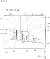
- Figure 4 shows a 3D game screen 200 representing a scene the same as the scene (position on the map) in Figure 3 .
- a viewpoint is moved to a different position from that when the game screen 100 is generated, and its direction is also changed. More specifically, the position of the viewpoint is switched to be at the back of the player character 102, and the direction of the viewpoint is switched so as to be directed to the direction of movement (x-axis direction).
- the player character 102, the ground object 104, and the step object 108 are displayed in a 3D manner.
- the step object 108 includes four components 108a, 108b, 108c, and 108d, and each of the components 108a-108d is placed in a position different in a z-axis direction as well as in an x-axis direction. Also, each of the components 108a-108d includes one or more block objects 106. Accordingly, the position (height) in the y-axis direction of each of the components 108a-108d is different depending on the number of the accumulated blocks.
- the background image 110 in the 2D game screen 100 is equal to a left side surface in a case the player character 102 is oriented to the direction of movement (x-axis direction) in the 3D game screen 200.
- the right side surface when the player character 102 is oriented to the direction of movement is not displayed.
- a transparent polygon (not illustrated) for detecting a contact is arranged on the right side surface to prevent the player character 102 from moving in a right direction (z-axis direction) with respect to the direction of movement.
- the right side surface when the 3D game screen 200 is displayed is equal to the near clipping plane when the 2D game screen 100 is displayed.
- the 2D game screen 100 can be displayed to advance the game while the 3D game screen 200 also can be displayed to advance the game.
- the player can switch the virtual camera (viewpoint) by operating any of the operating portions 26 of the controller 22.
- the player advances the game by selectively displaying the 2D game screen 100 and the 3D game screen 200 to conquer the game (map).
- the player makes the player character 102 advance in the direction of movement (x-axis direction) across a portion where the ground object 104 and the step object 108 are absent (do not exist). That is, in the virtual three-dimensional space, the step object 108 is separated into the components 108a-108d, and no ground object 104 is placed between each of the components 108a-108d, and therefore, the player character 102 is apt to fall (downwardly move in the y-axis direction).
- the step object 108 is integrally displayed like a step, and therefore, if the player character 102 moves on the step object 108, it never falls. That is, in such a scene, the player character 102 can be moved more easily when being displayed in the 2D game screen 100 than when being displayed in the 3D game screen 200.
- the player character 102 is subjected to a modeling in the three-dimensional manner, and even if the 2D game screen 100 is displayed, the player character 102 moves in the 3D virtual space.
- the player character 102 moves in the direction of movement (x-axis direction) through the space between the component 108a and the component 108b in the z-axis direction of the virtual tree-dimensional space, the player character 102 causes the inconvenience of falling through the block object 106 on the 2D game screen 100 even though it moves on the step object 108.
- the player character 102 has to fall at a position of no ground object 104 between the component 108a and component 108b.
- collision data (2D collision data 404h) for displaying a predetermined object (step object 108 in this embodiment) in the 2D game screen 100 and the collision data (3D collision data 404i) for displaying it in the 3D game screen 200 are prepared so as to be selectively utilized.
- a polyhedron for detecting contact 120 shown in Figure 5 is arranged to the step object 108.
- the polyhedron 120 includes a plurality of transparent polygons 120a, and is invisible in a case that the game screen 100 is actually displayed.
- the polyhedron 120 is formed by a plurality of polygons 120a in a horizontally-long step shape. The width of the polyhedron 120 is sectioned by the near clipping plane and the far clipping plane in the z-axis direction.
- the player character 102 moves on the step object 108, the player character 102 is displayed so as to contact the polyhedron 120 wherever it is in the z-axis direction, and so as not to fall from the step object 108.
- the outline of the polygons 120a is represented.
- the Z value is different in each of the components 108a-108d.
- polyhedrons for detecting contact 130, 140, 150, and 160 are respectively arranged for the components 108a-108d. More specifically, the polyhedron 130 is set with respect to the component 108a, the polyhedron 140 is set with respect to the component 108b, the polyhedron 150 is set with respect to the component 108c, and the polyhedron 160 is set with respect to the component 108d.
- the polyhedron 130 includes a plurality of polygons 130a
- the polyhedron 140 includes a plurality of polygons 140a
- the polyhedron 150 includes a plurality of polygons 150a
- the polyhedron 160 includes a plurality of polygons 160a.
- the player character 102 needs to jump toward the ground object 104 of the opposite shore. This is because if the player character does not reach the ground object 104 of the opposite shore, the player object displays such that it falls down and then dies out. That is in such a case, the player character 102 does not contact the polyhedron 130-160, so that it does not ride on any of the components 108a-108d.
- Figure 5 and Figure 6 show a state when a virtual three-dimensional space (game) is obliquely viewed by placing a virtual camera (viewpoint) in a position different from that in the game screen 100 shown in Figure 3 and the game screen 200 shown in Figure 4 .
- a plurality of vectors for performing a contact detection is set to the player character 102.
- a plurality of vectors P from the central axis (axis in parallel with the Y axis) of the player character 102 to the outside are set to the player character 102.
- each of the vectors P is the same in size.
- the collision data to be used is different depending on the fact that the game screen currently being displayed is a 2D display or a 3D display. That is, if the 2D game screen 100 is displayed, the collision data for 2D (404h shown in Figure 9 ) is utilized, and if the 3D game screen 200 is displayed, the collision data for 3D (404i shown in Figure 9 ) is utilized.
- a polyhedron (polyhedron 120, polyhedrons 130-160, for example) including a plurality of transparent polygons are set to the predetermined object (step object 108, for example) according to the prepared collision data.
- a contact detection is performed by utilizing the collision data prepared in advance, it is determined that each of the polygons (120a-160a) included in the polyhedron (120-160) set in accordance with the collision data and the vector P are contacted with each other. More specifically, the presence or absence of the contact is determined depending on whether or not the vector P and the polygonal plane cross each other, or whether or not the vector P is included in the polygonal plane.
- the contact detection is performed by use of the 3D collision data, detection is made on all the vectors P set to the player character 102. That is, a contact detection is performed in the x-axis direction, the y-axis direction, and the z-axis direction on the virtual three-dimensional space.
- the contact detection is made by use of the 2D collision data, only a direction in parallel with the X axis out of the vectors P set to the player characters 102 is utilized. That is, a contact detection as to the z-axis direction is not performed, and the contact detection as to only the x-axis direction and the y-axis direction are executed. That is, the z-axis direction is neglected.
- collision data collision data (simple data as to a plane figure or a solid figure in this embodiment) of the enemy object and the item object are created (calculated) every time that the contact detection is required. Also, in such a case, in order to simply perform the contact detection, the collision data is also created as to the player character 102 similarly to other objects.
- the player character 102, the enemy object, and the item object are displayed in the form of a plane figure (plane figure in parallel with X and Y planes in this embodiment), such as a circle, a rectangle (oblong and square) such that the outlines thereof are enclosed. That is, the height (length in the Y-axis direction) and the width (length in the X-axis direction) of the player character 102, the enemy object, and the item object are obtained, and the plane figure is calculated on the basis of the height and the width in the X and Y axes (X and Y planes).
- the player character 102, the enemy object, and the item object are displayed in the form of solid figure, such as a round, a column, a cube, a rectangular parallelepiped, and the like such that the outlines thereof are enclosed. That is, the height (length in the Y-axis direction), the width (height in the X-axis direction), and the depth (length in the Z-axis direction) of the player character 102, the enemy object, and the item object are obtained, and the solid figure in the X, Y, and Z axes (virtual three-dimensional space) is calculated on the basis of the height, the width, and the depth.
- a contact detection is described when the figure corresponding to the collision data of the object (210 and 212, here) is set (calculated) to a quadrangular prism shape, such as a rectangular parallelepiped or a cube.
- the object 210 has the position coordinates (central coordinates) of (Xo1, Yo1, Zo1), and the length in the X-axis direction (in the horizontal direction), the length in the Y-axis direction (in the vertical direction), and the length in the Z-axis direction (in the depth direction) are L1, L2, and L3, respectively.
- the object 212 has the position coordinates (central coordinates) of (Xo2, Yo2, Zo2), and the length in the X-axis direction (in the horizontal direction), the length in the Y-axis direction (in the vertical direction), and the length in the Z-axis direction (in the depth direction) are H1, H2, and H3, respectively.
- the outline of each of the objects is set to the quadrangular prism shape, if the distance (distance between centers) d of the objects and the length of each side satisfies all the following equations 1-3, it is determined that the object 210 and the object 212 are contacted with each other.
- the dx, the dy, and the dz are respectively the X component, the Y component, and the Z component of the distance between centers d. Furthermore, each of the components dx, dy, and dz of the distance between centers d is calculated according to the equation 4.
- FIG. 8 (B) a description is made on a contact detection in case that the figure corresponding to the collision data of the object (220, 222, here) is set (calculated as) to a round shape (shown in a two dimensional circle in the drawing for simplicity).
- the object 220 is the position coordinates (central coordinates) (Xo3, Yo3, Zo3), and has a radius R.
- the object 222 is the position coordinates (central coordinates) (Xo4, Yo4, Zo4), and has a radius r.
- FIG. 9 shows a memory map of the main memory 40.
- the main memory 40 includes a program storage area 402 and a data storage area 404.
- a game program of the action game in this embodiment is stored in the program storage area 402.
- the game program includes a game main processing program 402a, an image generating program 402b, an image displaying program 402c, an operation information obtaining program 402d, a player character controlling program 402e, an object controlling program 402f, a viewpoint switching program 402g, a viewpoint controlling program 402h, a contact detection program 402i, etc.
- the game main processing program 402a is a program for processing a main routine of the action game.
- the image generating program 402b is a program for generating a game image including a player character 102, a non-player object such as an enemy object, an item object, a background object (104,106,108), etc. existing in a virtual game space (virtual three-dimensional space).
- the player character 102 means a moving character moving around, and so forth in the virtual three-dimensional space according to an operation by the player.
- the non-player object is an object moving according to the program independent of player's operation.
- the background object is an object as to a background, such as a wall, a floor (ground), a pillar, a tree, etc. These background objects are arranged to form a map of the action game.
- the image displaying program 402c is a program for displaying on the monitor 34 a game image generated according to execution of the image generating program 402b.
- the operation information obtaining program 402d is a program for obtaining operation information (operation input) by the player, and detects operation data (operation signal) input from the controller 22 via the controller I/F56 to store it in the data storage area 404.
- the player character controlling program 402e is a program for calculating position coordinates (three-dimensional coordinates) of the moved player character 102 corresponding to the operation data obtained according to the operation information obtaining program 402d to update a current position, and making the player character 102 perform an arbitrary action, and so forth. Also, the player character controlling program 402e executes a process of reducing the life of the player character 102 according to a detection result of the contact detection program 402h described later, annihilating the player character 102 and the enemy object, making the player character 102 obtain an item, destroying a block object 106, and so forth.
- the object controlling program 402f is a program for moving a non-player object such as an enemy object in the virtual three-dimensional space. Also, the object controlling program 402f is a program for decreasing the life of the player character 102 depending on a detection result of the contact detection program 402h, annihilates the player character 102 and the enemy object, making the player character 102 obtain an item, destroying the block object 106, and so forth.
- the viewpoint switching program 402g is a program for switching the virtual camera (viewpoint) arranged in the virtual three-dimensional space.
- the viewpoint switching program 402g is a program for switching between the virtual camera (viewpoint) position and the direction of the viewpoint for generating the 2D game screen 100, and the viewpoint position and the direction of the viewpoint for generating the 3D game screen 200. It should be noted that the viewpoint switching program 402g obtains viewpoint data (data of the position of the viewpoint and the direction of the viewpoint) to be stored in correspondence to the current position of the player character 102 from the viewpoint parameter for 2D (2D viewpoint parameter 404f) or the viewpoint parameter for 3D (3D viewpoint parameter 404g).
- the viewpoint controlling program 402h is a program for controlling the movement of the virtual camera (viewpoint), that is, the change of the position of the viewpoint, and the change of the direction of the viewpoint. More specifically, the viewpoint controlling program 402h updates the X coordinate and the Y coordinate according to the operation input from the controller 22, that is, according to the movement of the player character 102 in a case that the 2D game screen 100 is displayed. It should be noted that in a case that the 2D game screen 100 is displayed, the Z coordinate of the viewpoint position is not changed until the operation input from the player. The viewpoint controlling program 402h updates each of the X coordinate, Y coordinate, and Z coordinate as if it follows the player character 102 in accordance with its movement in a case that the 3D game screen 200 is displayed.
- the player can change the position of the virtual camera (viewpoint) and the direction of the viewpoint (position of the center of the interest) by utilizing the controller 22.
- the change is stored (set) in the data storage area of the main memory 40. Therefore, when the position of the viewpoint and the direction of the viewpoint are changed, the position of the viewpoint is updated according to the movement of the player character 102 such that a positional relationship between the changed viewpoint position and the player character 102 is maintained, and the changed viewpoint direction is maintained.
- the contact detection program 402i is a program for detecting that the player character 102 and other objects (104, 106, 108, etc.) are contacted (hit, collided) with each other, and is a program for detecting that the enemy objects are contacted with each other.
- miscellaneous programs such as a game sound reproducing program, a backup program, etc. are stored.
- the game sound reproducing program is a program for generating a sound necessary for the game, such as voices or an onomatopoeic sound of the character (object) appearing in the game, game music like a BGM, a sound effect, etc.
- the backup program is a program for storing in the memory card 30 game data (proceeding data or result data of the game) stored (or temporarily stored) in the main memory 40 according to a predetermined event and player's instruction.
- image data 404a image data 404a, operation data 404b, player character data 404c, object data 404d, viewpoint data 404e, 2D viewpoint parameter data 404f, 3D viewpoint parameter data 404g, 2D collision data 404h, 3D collision data 404i, 2D flag data 404j, etc.
- the image data 404a is data (polygon data and texture data) for rendering characters and objects, such as a player character 102, an enemy object, an item object, a background object (ground object 104, block object 106, step object 108, etc.), and for rendering the background image 110.
- the operation data 404b is operation data input from the controller 22 according to the player operating the operating means of the controller 22.
- the character data 404c is data (coordinates data) as to the current three-dimensional position (three-dimensional coordinates) of the player character 102 in the virtual three-dimensional space.
- the character data 404c is updated according to player's operation input.
- the object data 404d is coordinates data as to the current three-dimensional position (three-dimensional coordinates) of the object, such as an enemy object, an item object, and a background object (104, 106, 108) in the three dimensional space.
- the coordinates data is stored in correspondence to each of the objects, and the coordinates data of the moving image object such as the enemy object is updated according to the program (according to the process by the CPU 36).
- the viewpoint data 404e is data (coordinates data) of the current three-dimensional position (three-dimensional coordinates) and data of the direction of viewpoint (angular data from a reference direction or coordinates data of the center of interest) of the virtual camera (viewpoint) in the virtual three-dimensional space.
- the 2D viewpoint parameter data 404f is viewpoint data to be referred when the 2D game screen 100 is displayed, and is set in advance in correspondence with each of the scenes or the position of the map.
- the 3D viewpoint parameter data 404g is viewpoint data to be referred when the 3D game screen 200 is displayed, and set in advance in correspondence with each of the scenes or the position of the map.
- the 2D collision data 404h is contact detection data prepared for a predetermined object (step object 108 in this embodiment) when the 2D game screen 100 is displayed. More specifically, it is coordinates (three-dimensional coordinates) data as to vertices of the each of the polygons (120a in this embodiment) comprising a polyhedron (120 in this embodiment).
- the 2D collision data 404h (the same is true for 3D collision data 404i) is table data in which a plurality of polygons are set corresponding to the predetermined object, and coordinates of the vertices of the polygon (three-dimensional coordinates) corresponding to each polygon is described.
- the 3D collision data 404i is contact detection data prepared for a predetermined object (step object 108 in this embodiment) when the 3D game screen 200 is displayed. More specifically, it is three-dimensional coordinates data as to the vertices of each of the polygons (130a, 140a, 150a, 160a in this embodiment) comprising a polyhedron (130, 140, 150, 160 in this embodiment).
- the 2D flag data 404j is flag data to determine whether or not the 2D game screen 100 is displayed.
- the 2D flag data 404j comprises 1 bit register, for example. If the flag is turned on (established), a data value "1" is set to the register, and if the flag is turned off (not established), a data value "0" is set to the register. It should be noted that if the 2D game screen 100 is displayed, the flag is turned on, and if the 3D game screen 200 is displayed, the flag is turned off.
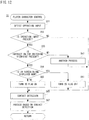
- the CPU 36 shown in Figure 2 executes a game entire process shown in Figure 10 .
- the CPU 36 first performs an initial setting in a step S1 when starting the game entire process. For example, if the game is started from the top, the buffer area of the main memory 40 is initialized, and an initial value is set to the flag data stored in the main memory 40. Also, if the game is started where the player left off, the game data stored in the memory card 30 is loaded.
- a viewpoint controlling process (see Figure 11 ) described later is executed
- a player character controlling process (see Figure 12 ) described later is executed.
- an object controlling process (see Figure 13 ) described later is executed
- an image generating process (see Figure 16 ) described later is executed.
- the image (game image) generated in the step S9 is displayed on the monitor 34.
- a step S13 it is determined whether or not a game is to be ended. That is, it is determined whether or not a game is over, or whether or not a game end is instructed by the player. If “NO” in the step S13, that is, if the game is not to be ended, the process returns to the step S3. On the other hand, if "YES” in the step S13, that is, if the game is to be ended, the game entire process is directly ended.
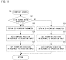
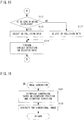
- FIG 11 is a flowchart showing a viewpoint controlling process in the step S3 shown in Figure 10 .
- the CPU 36 determines whether or not the 2D screen is being displayed in a step S21 when starting the viewpoint controlling process. That is, referring to the 2D flag data 404j, it is determined whether or not the 2D flag is turned on. If "YES" in the step S21, that is, if the 2D flag is turned on, it is determined that the 2D screen is being displayed, and then, the 2D viewpoint parameter data 404f is obtained in a step S23. Strictly speaking, in the step S23, with referring to the player character data 404c, the current position of the player character 102 is obtained, and the 2D viewpoint parameter data 404f (viewpoint data) stored in correspondence with the current position is obtained.
- step S25 the position of the viewpoint is set (changed) in response to the operation input, and in a step S27, the direction of the viewpoint is set (changed) in response to the operation input, and then, the process returns to the game entire process shown in Figure 10 .
- the process in the step S25 and the step S27 are not executed.
- the 3D viewpoint parameter data 404g is obtained in a step S29. Strictly speaking, in the step S29, with referring to the player character data 404c, the current position of the player character 102 is obtained, and the 3D viewpoint parameter data 404g (viewpoint data) stored in correspondence to the current position is obtained.
- step S31 in response to the operation input, the position of the viewpoint is set (changed), and in a step S33, the direction of the viewpoint is set (changed) in response to the operation input, and then, the game entire process is returned. It should be noted that if no operation input is present from the player, that is, if the operation data 404b is not stored in the data storage area 404, or even if the operation data 404b is stored, but it has nothing to do with the viewpoint control, the process in the steps S31 and S33 are not executed.
- FIG 12 is a flowchart showing a player character controlling process in the step S5 shown in Figure 10 .
- the CPU 36 detects an operation input in a step S51 when starting the player character controlling process. That is, the data storage area 404 is referred.
- step S53 it is determined whether or not the operation input is present. That is, it is determined whether or not the operation data 404b is stored in the data storage area 404. If “NO” in the step S53, that is, if the operation input is not present, the process directly proceeds to a step S65. On the other hand, if "YES” in the step S53, that is, if the operation input is present, it is determined whether or not the operation input is an instruction for switching the viewpoint in a step S55. If "NO” in the step S55, that is, if the operation input is not the instruction for switching the viewpoint, another process is executed in a step S57, and then, the process proceeds to the step S65. For example, in the step S57, the player makes the player character 102 move or perform an arbitrary action.
- step S55 determines whether or not the operation input is the instruction for switching the viewpoint. That is, it is determined whether or not the 2D screen is being displayed now in a step S59. That is, it is determined whether or not the 2D flag is turned on. If “YES” in the step S59, that is, if the 2D flag is turned on, the 2D flag is turned off to switch to the 3D screen in a step S61, and then, the process proceeds to the step S65.
- step S59 that is, if the 2D flag is turned off, it is determined that the 3D screen is being displayed now, the 2D flag is turned on in order to switch to the 2D screen in a step S63, and then, the process proceeds to the step S65.
- a contact detection process (see Figure 14 and Figure 15 ) described later is executed.
- a process based on the contact detection is executed, and then, the process returns to the entire process shown in Figure 10 .
- the player character 102 contacts the item, it obtains the item.
- the player character 102 contacts the enemy character, the player character 102 is damaged, or annihilates the enemy character. According thereto, the life of the player character 102 is subtracted, the point is added, and so forth.
- the player character 102 contacts the ground object 104 and the step object 108, the player character 102 can move on it, or is hindered its progress by the step object 108.
- Figure 13 is a flowchart showing an object controlling process in the step S7 shown in Figure 10 .
- an object game process is executed in a step S81. This makes the enemy character appear or move, and makes an item appear and disappear.
- a contact detection process described later is executed in a next step S83.
- a process based on the contact detection is executed to return to the entire process shown in Figure 10 .
- step S85 is similar to the above-described player character controlling process ( Figure 12 ) in the step S67.
- FIG 14 and Figure 15 is a flowchart showing the contact detection process in the step S65 in Figure 12 and in the step S83 in Figure 13 .
- the CPU 36 determines whether or not an object is an object utilizing the collision data in a step S101 when the contact detection process is started. That is, it is determined whether or not the collision data is prepared (stored) with respect to the object on which a contact detection is performed. If "YES” in the step S101, that is, if the object is an object utilizing the collision data, the process proceeds to a step S113 shown in Figure 15 . However, if "NO" in the step S101, that is, if the object is not an object utilizing the collision data, it is determined whether or not the 2D screen is being displayed with referring to the 2D flag data 404j in a step S103.
- step S103 If “YES” in the step S103, that is, if the 2D screen is being displayed, the height and the width of the object is obtained in a step S105, a contact detection is performed on the circle and the rectangle in the X and Y axes in a step S107, and then, the contact detection process is returned.
- step S109 if "NO” in the step S103, that is, if the 3D screen is being displayed, the height, width and depth of the object are obtained in a step S109, a contact detection is performed on the round and cube (rectangular parallelepiped) in the X, Y, and Z axes in a step S111, and then, the contact detection process is returned.
- step S113 it is determined whether or not the 2D screen is being displayed in the step S113. If “YES” in the step S113, that is, if the 2D screen is being displayed, the 2D collision data 404h is selected (read) in a step S115, and then, the process proceeds to a step S119. On the other hand, if "NO” in the step S113, that is, if the 3D screen is displayed, the 3D collision data 404i is selected (read) in a step S117, and then, the process proceeds to the step S119. In the step S119, a contact detection is performed on the selected (read) data, and then, a contact detection process is returned as shown in Figure 14 .
- FIG 16 is a flowchart showing an image generating process in the step S9 shown in Figure 10 .
- the CPU 36 executes a viewpoint transformation on the basis of the position of the viewpoint and the direction of the viewpoint in a step S131. That is, with referring to the viewpoint data 404e stored in the data storage area 404 of the main memory 40, the current position of the viewpoint and direction of the viewpoint are obtained so as to be converted into camera coordinates, regarding the current viewpoint (camera position) as an original point, and the current direction of viewpoint as the z-axis direction of the camera coordinates. Then, in a step S133, a two dimensional image is generated, and then, the entire process is returned as shown in Figure 10 . In the step S133, a virtual three-dimensional space viewed from the viewpoint is focused on a virtual screen, that is, converted into the camera coordinates to generate a two-dimensional image.
- the 2D collision data and the 3D collision data are prepared in correspondence with a predetermined object, and a contact detection is performed by utilizing any one of them.
- the player can enjoy playing a pseudo 2D game in the 3D game, and gain interest of the game utilizing the properties of the 2D game and the 3D game.
- not only combining the 2D game and the 3D game, but also unifying them it becomes possible to more decrease a processing load and increases an available memory than that in a case of combining both of them.
- a contact detection is performed on only the x-axis direction and the y-axis direction, it is not limited thereto.
- a contact detection may be performed on only the x-axis direction by neglecting the y-axis direction and the z-axis direction, and a contact detection may also be performed on only the y-axis direction by neglecting the x-axis direction and the z-axis direction. That is, for each virtual game, any detection method may be applicable.
Description
- The present invention relates to a game apparatus and a storage medium storing game program. More specifically, the present invention relates to a game apparatus which has an operating means with which a player performs an operation input, a display means for displaying a game image, and storage means for storing in advance data to generate at least a virtual three-dimensional space, and a storage medium storing game program.
- One example of a related art is disclosed in "Super Mario 64 Otasuke Guide", First edition, published by Soft Bank Co. Ltd., on September 7, 1996, on . According to this document, a player operates a hero character (player character) to move the player character on a map developed in a three-dimensional space, and conquers the game by attacking an enemy character, and so forth.
- Another example of the related art is disclosed in "Super Mario Brothers Urawaza Taizensyu", the 19-th edition, Futami Shobo Co. Ltd, on March 31, 1986, on . According to this document, an initial video game is proposed, in which a player character moves in a two-dimensional map to be scrolled in a horizontal direction according to player's operation, and conquers the game by attacking an enemy character, and so forth.
- A further example of the related art is
US 6,050,896 . According to this document, a three-dimensional game space is transformed into a two-dimensional projection viewpoint and the judgment of a collision is based on the positions of display objects in the two-dimensional projection. Another related art isUS 6,128,018 , which discloses collision detections in the three-dimensional space. As described above, the three-dimensional game is disclosed in the Super Mario 64 Otasuke Guide, and the two-dimensional game is disclosed in the Super Mario Brothers Urawaza Taizensyu. It is a common recognition that the two-dimensional game is developed into the three-dimensional game. The respective games have a specific amusement, and cannot be compared with each other. However, there is no game for pursuing a further enjoyment of the game by combining the respective properties. - Of course, it is easily conceivable that the respective games are simply combined, but data for two-dimensional game and data for three-dimensional game are required, resulting in a lot of processing load and a large memory capacity.
- Therefore, it is a primary object of the present invention to provide a novel game apparatus and storage medium storing game program.
- Another object of the present invention is to provide a game apparatus and a storage medium storing game program which can increase interest of the game by utilizing properties of a two-dimensional game and of a three-dimensional game.
- The other object of the present invention is to provide a game apparatus and a storage medium storing game program capable of enjoying playing a two-dimensional game by utilizing a three-dimensional game space.
- The present invention employs following a configuration in order to solve the above-described problems. It should be noted that reference numerals and supplement inside the parentheses show one example of a corresponding relationship with the embodiments described later for easy understanding of the present invention, and does not limit the present invention.
- A game apparatus according to the present invention has an operating means with which a player makes an operation input, a display means for displaying a game image, and a storage means for storing in advance data for generating at least a virtual three-dimensional space. The game apparatus includes an input detecting means, a player character controlling means, an object controlling means, a contact detection means, a viewpoint controlling means, and a viewpoint switching means. The input detecting means detects input data corresponding to an operation input from the operating means, and temporarily stores it in the storage means. The player character controlling means arranges a player character to be operated by the player in the virtual three-dimensional space by utilizing player character data stored in the storage means in response to first input data temporarily stored by the input detecting means. The object controlling means arranges an object not to be operated by the player in the virtual three-dimensional space by utilizing object data stored in the storage means. The contact detection means determines whether or not the player character and a predetermined object are contacted with each other. The viewpoint controlling means controls a viewpoint in the virtual three-dimensional space. The viewpoint switching means switches the viewpoint depending on second input data temporarily stored by the input detecting means. The contact detection means changes contact detection data set to the predetermined object depending on a switching result of the viewpoint switching means.
- More specifically as set out in the appended claims, a game system (12) has an operating means (22, 26) with which a player makes an operation input, a display means (34) for displaying a game image, and a storage means (40) for storing in advance data for generating at least a virtual three-dimensional space. The game apparatus further includes an input detecting means (36, S51), a player character controlling means (36, S5), an object controlling means (36, S7), contact detection means (36, S9), a viewpoint controlling means (36, S3), and a viewpoint switching means (36, S21, S23, S29). The input detecting means detects input data corresponding to an operation input from the operating means, and temporarily stores it in the storage means. The player character controlling means arranges a player character to be operated by the player in the virtual three-dimensional space by utilizing player character data (404c) stored in the storage means in response to first input data temporarily stored by the input detecting means. For example, the player character is moved in response to an operation input from the operating means within the virtual three-dimensional space. The object controlling means arranges an object not to be operated by the player in the virtual three-dimensional space by utilizing object data (404d) stored in the storage means. For example, a computer or a processor (36) causes an enemy object to appear, move independent of player's operation according to a program, and arrange (generate) an item object and a background object (104,106,108). The contact detection means determines whether or not the player character and a predetermined object are contacted with each other. The viewpoint controlling means controls a viewpoint (virtual camera) in the virtual three-dimensional space. For example, a position of the viewpoint is updated according to the movement of the player character. The viewpoint switching means switches the viewpoint depending on second input data temporarily stored by the input detecting means. For example, according to an instruction of switching the viewpoint by the player, the position and the direction of the viewpoint are switched. The contact detection means changes the contact detection data set used for contact detection between said player character and said predetermined object depending on a switching result of the viewpoint switching means. According to the present invention, the viewpoint switching means (36, S21, S23, S29) is adapted to switch the viewpoint between a three-dimensional game screen (200) and a two-dimensional game screen (100). According to the present invention, a contact detection is executed by utilizing contact detection data depending on the viewpoint, so that a player can enjoy playing a game by viewing a different game screen depending on the viewpoint.
- In particular, the contact detection data includes first detection data for performing a contact detection on all three dimensions of the virtual three-dimensional space and second detection data for performing a contact detection on one dimension or a combination of any two dimensions of the virtual three-dimensional space, and the contact detection means selects any one of the first detection data and the second detection data depending on a switching result of the viewpoint switching means. More specifically, the contact detection data includes first detection data (404i) for performing a contact detection on all three dimensions of the virtual three-dimensional space and second detection data (404j) for performing a contact detection on one dimension or a combination of any two dimensions of the virtual three-dimensional space. For example, the first detection data is data for performing a contact detection in an x-axis direction, a y-axis direction, and a z-axis direction within a virtual three-dimensional space. Furthermore, the second detection data is data for performing a contact detection within the virtual three-dimensional space in one or a combination of any two of the x-axis direction, the y-axis direction, and the z-axis direction (x-axis direction and y-axis direction, y-axis direction and z-axis direction, and z-axis direction and x-axis direction). The contact detection means selects any one of the first detection data and the second detection data depending on a switching result of the viewpoint switching means. A contact detection is performed on the three-dimensional display and the two (one) dimensional display, and therefore, it is possible to perform a contact detection in a first-dimensional or a second-dimensional manner in the three-dimensional game. According to the present invention, the first detection data (404i) is used when the three-dimensional game screen (200) is displayed and the second detection data (404h) is used when the two-dimensional game screen (100) is displayed. In one aspect of the present invention, the game apparatus further includes a mode switching means for switching between a first mode for switching to a view of all three dimensions of the virtual three-dimensional space by the viewpoint switching means and a second mode for switching to a view by combining one dimension or a combination of any two dimensions of the virtual three-dimensional space by the viewpoint switching means. The contact detection means selects the first detection data when the mode switching means switches to the first mode, and the contact detection means selects the second detection data when the mode switching means switches to the second mode. More specifically, the game apparatus further includes a mode switching means (36, S55, S59, S61, S63). The mode switching means switches between a first mode for switching to a view of all three dimensions of the virtual three-dimensional space by the viewpoint switching means and a second mode for switching to a view by combining one dimension or a combination of any two dimensions of the virtual three-dimensional space by the viewpoint switching means. Accordingly, in the first mode, a switching of the viewpoint is performed on all of the x-axis direction, the y-axis direction, and the z-axis direction. On the other hand, in the second mode, a switching of the viewpoint is performed on one or a combination of any two of the x-axis direction, the y-axis direction, and the z-axis direction (x-axis direction and y-axis direction, y-axis direction and z-axis direction, and z-axis direction and x-axis direction). Thus, the contact detection means selects the first detection data when the mode switching means switches to the first mode, and the contact detection means selects the second detection data when the mode switching means switches to the second mode. The viewpoint can thus be switched, so that a player can enjoy playing a game while viewing a different game screen depending on the viewpoint. For example, it is possible to play a game by displaying the game screen of the three-dimensional game in a two-dimensional manner.
- A storage medium storing game program according to the present invention stores a game program of a game apparatus having an operating means with which a player makes an operation input, a display means for displaying a game image, and a storage means for storing in advance data for generating at least a virtual three-dimensional space. The game program makes a processor of the game apparatus function as an input detecting means, a player character controlling means, an object controlling means, a contact detection means, a viewpoint controlling means, and a viewpoint switching means. The input detecting means detects input data corresponding to an operation input from the operating means, and temporarily stores it in the storage means. The player character controlling means arranges a player character to be operated by the player in the virtual three-dimensional space by utilizing the player character data stored in the storage means in response to first input data temporarily stored in the input detecting means. The object controlling means arranges an object not to be operated by the player in the virtual three-dimensional space by utilizing the object data stored in the storage means. The contact detection means determines whether or not the player character and the predetermined object are contacted with each other. The viewpoint controlling means controls a viewpoint in the virtual three-dimensional space. The viewpoint switching means switches the viewpoint depending on second input data temporarily stored by the input detecting means. The contact detection means changes the data set used for contact detection between said player character and said predetermined object depending on a switching result of said viewpoint switching means.
- The contact detection data includes first detection data for performing a contact detection on all three dimensions of the virtual three-dimensional space and second detection date for performing a contact detection in one dimension or a combination of any two dimensions of the virtual three-dimensional space. The contact detection means selects any one of said first detection data and said second detection data depending on a switching result of said viewpoint switching means.
- In this invention also, similarly to the above-described game apparatus, a player can enjoy playing a game by viewing different game screen depending on the viewpoint.
- The above described objects and other objects, features, aspects and advantages of the present invention will become more apparent from the following detailed description of the present invention when taken in conjunction with the accompanying drawings.
-
Figure 1 is an illustrative view showing a game system of one embodiment of the present invention; -
Figure 2 is a block diagram showing an electric configuration of the game system shown inFigure 1 ; -
Figure 3 is an illustrative view showing one example of a 2D game screen displayed on a monitor shown inFigure 1 ; -
Figure 4 is an illustrative view showing one example of a 3D game screen displayed on the monitor shown inFigure 1 ; -
Figure 5 is an illustrative view showing one example of a polyhedron for detecting contact set to a step object in a case that the 2D game screen shown inFigure 3 is being displayed; -
Figure 6 is an illustrative view showing one example of a polyhedron for detecting contact set to the step object when the 3D game screen shown inFigure 4 is displayed; -
Figure 7 is an illustrative view showing a vector for contact detection which is set to a player character; -
Figure 8 is an illustrative view for explaining a contact detection performed between objects; -
Figure 9 is an illustrative view showing a memory map of a main memory shown in Figure; -
Figure 10 is a flowchart showing a game entire process of a CPU shown inFigure 2 ; -
Figure 11 is a flowchart showing a viewpoint controlling process of the CPU shown inFigure 2 ; -
Figure 12 is a flowchart showing a player character controlling process of the CPU shown inFigure 2 ; -
Figure 13 is a flowchart showing an object controlling process of the CPU shown inFigure 2 ; -
Figure 14 is a flowchart showing a part of a contact detection process of the CPU shown inFigure 2 ; -
Figure 15 is a flowchart showing another part of the contact detection process of the CPU shown inFigure 2 ; and -
Figure 16 is a flowchart showing an image generating process of the CPU shown inFigure 2 . - Referring to
Figure 1 , avideo game system 10 of one embodiment of the present invention includes avideo game apparatus 12. Thevideo game apparatus 12 includes an approximatelycubic housing 14, and thehousing 14 is provided with anoptical disk drive 16 on an upper surface thereof. Anoptical disk 18 which is one example of an information storage medium storing a game program, and the like is mounted on theoptical disk drive 16. Thehousing 14 is provided with a plurality of connectors 20 (four in this embodiment) on a front surface thereof Theseconnectors 20 are for connecting acontroller 22 to thevideo game apparatus 12 by acable 24, and can connect up to four controllers to thevideo game apparatus 12 in this embodiment. - The
controller 22 is provided with an operating portion (operating switch) 26 on upper, lower, lateral sides and etc. thereof. The operatingportion 26, for example, includes two analog joysticks, one cross switch, a plurality of button switches, and so on. One analog joystick is utilized for inputting a moving direction and/or a moving speed, moving amount and etc. of a player character (a moving image character object, operable with thecontroller 22 by a player) according to an amount and a direction of an inclination of the stick. The other analog joystick is utilized for controlling a movement of the virtual camera according to a direction of an inclination thereof. The cross switch is utilized for instructing a moving direction of the player character in place of the analog joystick. The button switches are utilized for instructing a movement of the player character, switching a point of view of the virtual camera in the three-dimensional image, adjusting the moving speed of the player character and etc. The button switches, for example, further control a menu selection and a movement of a pointer or a cursor. - It should be noted that the
controller 22 is connected to thevideo game apparatus 12 by thecable 24 integrated into thecontroller 22 in this embodiment. However, thecontroller 22 may be connected to thevideo game apparatus 12 by another method such as a wireless manner via an electromagnetic wave (radio wave, infrared ray, for example). Furthermore, a detailed structure of the operatingportion 26 of thecontroller 22 is, of course, not limited to the structure of the embodiment, and can be arbitrarily changed or modified. For example, the only one analog joystick may be utilized, or no analog joystick may be utilized. The cross switch may not be utilized. - At least one or plurality of (two in this embodiment)
memory slots 28 are provided below theconnectors 20 on the front surface of thehousing 14 of thevideo game apparatus 12. Amemory card 30 is inserted to thismemory slot 28. Thememory card 30 is utilized for loading the game program, etc. read from theoptical disk 18 so as to temporarily store it, or saving game data of the game (result data or progress data of the game) that the player plays by utilizing thegame system 10. - The
housing 14 of thevideo game apparatus 12 is provided with an AV cable connector (not shown) on its rear surface. The connector allows amonitor 34 to be connected to thevideo game apparatus 12 over anAV cable 32. Themonitor 34 is typically a color television receiver, and theAV cable 32 inputs a video signal from thevideo game apparatus 12 to a video input terminal of the color television and inputs a sound signal to a sound input terminal. Accordingly, a game image of a three-dimension (3D) video game, for example, is displayed on the color television (monitor) 34, and a game sound (stereo game sound) such as a game music, a sound effect, etc. is output from right and leftspeakers 34a. - In the
game system 10, a user or a game player first turns on an electric power source of thevideo game apparatus 12 in order to play a game (or another application), and then selects a suitableoptical disk 18 storing a video game (or another application the play wants to play), and loads theoptical disk 18 on thedisk drive 16 of thevideo game apparatus 12. In response thereto, thevideo game apparatus 12 starts to execute the video game or another application on the basis of software stored in theoptical disk 18. The player operates thecontroller 22 so as to apply an input to thevideo game apparatus 12. For example, the player starts the game or another application by operating any one of the operatingportion 26. By moving another of the operatingportion 26, it is possible to move the moving image object (player character) in different directions and to change a viewpoint of the user (camera position) in the three-dimensional (3D) game world. -
Figure 2 is a block diagram showing an electric configuration of thevideo game system 10 ofFigure 1 embodiment. Thevideo game apparatus 12 is provided with a central processing unit (hereinafter, may be referred to as "CPU") 36. TheCPU 36 is called a computer or a processor, and is in charge of governing overall control of thevideo game apparatus 12. TheCPU 36 or the computer functions as a game processor and is connected with amemory controller 38 via a bus. Thememory controller 38 mainly controls writing to and reading from amain memory 40 connected via a bus under control of theCPU 36. Thememory controller 38 is connected with a GPU (Graphics Processing Unit) 42. - The
GPU 42 forms a part of a rendering means, and is constructed by a single chip ASIC, for example. TheGPU 42 receives a graphics command from theCPU 36 via thememory controller 38, and, in response to the command, generates the three-dimensional (3D) game image by ageometry unit 44 and arendering unit 46. Specifically, thegeometry unit 44 performs a coordinate operation process such as turn-around or rotation, movement, transformation, etc. of a variety of objects and objects (which is formed by a plurality of polygons, and the polygon is a polygonal plane defined by at least three vertex coordinates) in a three-dimension coordinates system. Therendering unit 46 performs an image generating process such as pasting a texture on each of polygons of the variety of objects, and so on. Thus, three-dimension image data to be displayed on the game screen is created by theGPU 42, and the image data is stored in theframe buffer 48. - It should be noted that data (primitive or polygon, texture and etc.) required to execute the construction command is acquired by the
GPU 42 from themain memory 40 via thememory controller 38. - The
frame buffer 48 is a memory for rendering (storing) one frame of the image data of theraster scan monitor 34, for example, and is rewritten by theGPU 42 every one frame. More specifically, theframe buffer 48 stores color information of the image for each pixel in order. Here, the color information is data as to R, G, B, and A, and is, for example, R (red) data of 8 bits, G (green) data of 8 bits, B (blue) data of 8 bits, and A (alpha) data of 8 bits. It should be noted that the A data is data as to a mask (mat image). A video I/F 58 described later reads the data stored in theframe buffer 48 via thememory controller 38 to display a 3D game image on the screen of themonitor 34. - Furthermore, a
Z buffer 50 has a storage capacity equal to the number of pixels corresponding to theframe buffer 48 ×the number of bits of depth data per one pixel, and stores depth information or depth data (Z value) of dots corresponding to respective storing positions of theframe buffer 48. - It should be noted that the
frame buffer 48 and theZ buffer 50 may be constructed by utilizing a portion of themain memory 40, or may be provided inside theGPU 42. - The
memory controller 38 is also connected to an RAM for audio 54 (hereinafter, to be referred as "ARAM") via a DSP (Digital Signal Processor) 52. Accordingly, thememory controller 38 controls the writing to and/or reading from theARAM 54 as a sub memory in addition to themain memory 40. - The
DSP 52 functions as a sound processor, and generates audio data corresponding to a sound required for the game, a sound or music by use of the sound data (not shown) stored in themain memory 40 or by use of sound wave form data written to theARAM 54. - The
memory controller 38 is further connected to respective interfaces (I/F) 56, 58, 60, 62 and 64 by buses. The controller I/F 56 is an interface for thecontroller 22 to be connected to thevideo game apparatus 12, and applies an operation signal or operation data of the operatingportion 26 of thecontroller 22 to theCPU 36 through thememory controller 38. The video I/F 58 accesses theframe buffer 48 to read the image data formed by theGPU 42 and then, applies the image signal or the image data (digital RGB pixel values) to themonitor 34 via the AV cable 32 (Figure 1 ). - The external memory I/
F 60 makes the memory card 30 (Figure 1 ) which is inserted to the front surface of thevideo game apparatus 12 communicate to thememory controller 38. This allows theCPU 36 to write and read the data to and from the memory card 30 (Figure 1 ) via thememory controller 38. The audio I/F 62 receives audio data applied from theDSP 52 through thememory controller 38 or an audio stream read from theoptical disk 18, and then applies an audio signal (sound signal) corresponding thereto to thespeakers 34a of themonitor 34. - The disk I/
F 64 connects thedisk drive 16 to thememory controller 38, and whereby theCPU 36 controls thedisk drive 16. By thedisk drive 16, a program, data, texture data, etc. read from theoptical disk 18 are written to themain memory 40 under control of theCPU 36. -
Figure 3 shows one example of agame screen 100 of a virtual game (action game) in this embodiment. Thegame screen 100 displays aplayer character 102, a ground object (floor object) 104, astep object 108 including a plurality of block objects 106, and abackground image 110. As understood fromFigure 3 , thegame screen 100 is displayed in a two dimensional (2D) manner such that theplayer character 102 is viewed from a side vertical to a direction of movement (x-axis direction). Although illustration is omitted, the2D game screen 100 is scrolled right to left, and up and down in accordance with the movement of theplayer character 102. Also, thegame screen 100 may be scrolled in a combined direction, such as the upper left, the lower left, the upper right, and the lower right. - It should be noted that strictly speaking, in the image processing of the
game apparatus 12, theplayer character 102 and the object (104, 106, 108, etc.) are subjected to a modeling process in the three dimension (3D). Accordingly, in a case that thegame screen 100 shown inFigure 3 is displayed, the position (three-dimensional position) and the direction of a virtual camera (viewpoint) not shown is set such that thegame screen 100 looks like a pseudo-two dimensional display. The direction (viewpoint direction) of the viewpoint can be represented by an angle formed with a reference direction (home position direction where a virtual camera is not panned and tilted) set in advance. Or, the viewpoint direction may be represented by position coordinates of the center of interest defined by a distance and an angle with respect to the viewpoint. - It should be noted that, in this embodiment, the
background image 110 is generated by pasting a texture on a billboard placed in a position indicated by a predetermined Z value in a 3-dimensional coordinates system, for example, a position corresponding to a far clipping plane in a case of displaying a2D game screen 100. - Also, in this embodiment, in order to distinguish the player character to be operated by the
player 102 from the object not to be operated by the player (104, 106, 108, etc.), a "character" and an "object" are separately utilized, but it is needless to strictly distinguish the "character" from the "object", and merely a difference in term. -
Figure 4 shows a3D game screen 200 representing a scene the same as the scene (position on the map) inFigure 3 . In thegame screen 200 shown inFigure 4 , a viewpoint is moved to a different position from that when thegame screen 100 is generated, and its direction is also changed. More specifically, the position of the viewpoint is switched to be at the back of theplayer character 102, and the direction of the viewpoint is switched so as to be directed to the direction of movement (x-axis direction). As can be understood fromFigure 4 , on thegame screen 200, theplayer character 102, theground object 104, and thestep object 108 are displayed in a 3D manner. Thestep object 108 includes fourcomponents components 108a-108d is placed in a position different in a z-axis direction as well as in an x-axis direction. Also, each of thecomponents 108a-108d includes one or more block objects 106. Accordingly, the position (height) in the y-axis direction of each of thecomponents 108a-108d is different depending on the number of the accumulated blocks. - It should be noted that the
background image 110 in the2D game screen 100 is equal to a left side surface in a case theplayer character 102 is oriented to the direction of movement (x-axis direction) in the3D game screen 200. Also, in the3D game screen 200, the right side surface when theplayer character 102 is oriented to the direction of movement is not displayed. However, in reality, a transparent polygon (not illustrated) for detecting a contact is arranged on the right side surface to prevent theplayer character 102 from moving in a right direction (z-axis direction) with respect to the direction of movement. - It should be noted that the right side surface when the
3D game screen 200 is displayed is equal to the near clipping plane when the2D game screen 100 is displayed. - Thus, even on the same scene, the
2D game screen 100 can be displayed to advance the game while the3D game screen 200 also can be displayed to advance the game. For example, the player can switch the virtual camera (viewpoint) by operating any of the operatingportions 26 of thecontroller 22. Thus, the player advances the game by selectively displaying the2D game screen 100 and the3D game screen 200 to conquer the game (map). - As understood from the
3D game screen 200 shown inFigure 4 , for example, in the scene shown inFigure 3 andFigure 4 , the player makes theplayer character 102 advance in the direction of movement (x-axis direction) across a portion where theground object 104 and thestep object 108 are absent (do not exist). That is, in the virtual three-dimensional space, thestep object 108 is separated into thecomponents 108a-108d, and noground object 104 is placed between each of thecomponents 108a-108d, and therefore, theplayer character 102 is apt to fall (downwardly move in the y-axis direction). On the other hand, in the2D game screen 100 shown inFigure 3 , thestep object 108 is integrally displayed like a step, and therefore, if theplayer character 102 moves on thestep object 108, it never falls. That is, in such a scene, theplayer character 102 can be moved more easily when being displayed in the2D game screen 100 than when being displayed in the3D game screen 200. - It should be noted that as described above, the
player character 102, etc., is subjected to a modeling in the three-dimensional manner, and even if the2D game screen 100 is displayed, theplayer character 102 moves in the 3D virtual space. Thus, without any treatment, if theplayer character 102 moves in the direction of movement (x-axis direction) through the space between thecomponent 108a and thecomponent 108b in the z-axis direction of the virtual tree-dimensional space, theplayer character 102 causes the inconvenience of falling through theblock object 106 on the2D game screen 100 even though it moves on thestep object 108. On the contrary thereto, in a case that the3D game screen 200 is displayed, theplayer character 102 has to fall at a position of noground object 104 between thecomponent 108a andcomponent 108b. - In order to avoid these problems, collision data (
2D collision data 404h) for displaying a predetermined object (step object 108 in this embodiment) in the2D game screen 100 and the collision data (3D collision data 404i) for displaying it in the3D game screen 200 are prepared so as to be selectively utilized. - More specifically, in a case that the
2D game screen 100 shown inFigure 3 is displayed, a polyhedron for detectingcontact 120 shown inFigure 5 is arranged to thestep object 108. Thepolyhedron 120 includes a plurality oftransparent polygons 120a, and is invisible in a case that thegame screen 100 is actually displayed. In addition, as understood fromFigure 5 , thepolyhedron 120 is formed by a plurality ofpolygons 120a in a horizontally-long step shape. The width of thepolyhedron 120 is sectioned by the near clipping plane and the far clipping plane in the z-axis direction. Thus, in a case that theplayer character 102 moves on thestep object 108, theplayer character 102 is displayed so as to contact thepolyhedron 120 wherever it is in the z-axis direction, and so as not to fall from thestep object 108. It should be noted that inFigure 5 (the same is true forFigure 6 ), for understanding the polyhedron for detectingcontact 120, the outline of thepolygons 120a is represented. - On the other hand, as to the
step object 108 of the3D game screen 200 shown inFigure 4 , the Z value is different in each of thecomponents 108a-108d. Accordingly, as shown inFigure 6 , polyhedrons for detectingcontact components 108a-108d. More specifically, thepolyhedron 130 is set with respect to thecomponent 108a, thepolyhedron 140 is set with respect to thecomponent 108b, thepolyhedron 150 is set with respect to thecomponent 108c, and thepolyhedron 160 is set with respect to thecomponent 108d. Furthermore, thepolyhedron 130 includes a plurality ofpolygons 130a, thepolyhedron 140 includes a plurality ofpolygons 140a, thepolyhedron 150 includes a plurality ofpolygons 150a, and thepolyhedron 160 includes a plurality ofpolygons 160a. - Accordingly, in a case that the player wants the
player character 102 to move to a place where nocomponents 108a-108d are arranged by operating thecontroller 22, theplayer character 102 needs to jump toward theground object 104 of the opposite shore. This is because if the player character does not reach theground object 104 of the opposite shore, the player object displays such that it falls down and then dies out. That is in such a case, theplayer character 102 does not contact the polyhedron 130-160, so that it does not ride on any of thecomponents 108a-108d. - It should be noted that for better understanding of the polyhedrons for detecting contact 120-160,
Figure 5 andFigure 6 show a state when a virtual three-dimensional space (game) is obliquely viewed by placing a virtual camera (viewpoint) in a position different from that in thegame screen 100 shown inFigure 3 and thegame screen 200 shown inFigure 4 . - Next, a description is made on the contact detection. First, a description is made on a method of detection whether the
player character 102 and the object to which collision data in advance is prepared are contacted with each other. In such a case, a plurality of vectors for performing a contact detection is set to theplayer character 102. As shown inFigure 7 , a plurality of vectors P from the central axis (axis in parallel with the Y axis) of theplayer character 102 to the outside are set to theplayer character 102. - It should be noted that in
Figure 7 , for the sake of simplicity, the vector P is represented by wedges. Also, for the sake of simplicity, inFigure 7 , the wedges are represented so as to protrude from the surface of theplayer character 102, but the start point of each vector P is actually on the central axis. Also, although it is difficult to understand it inFigure 7 , each of the vectors P (scalar) is the same in size. - Furthermore, in such a case, the collision data to be used is different depending on the fact that the game screen currently being displayed is a 2D display or a 3D display. That is, if the
2D game screen 100 is displayed, the collision data for 2D (404h shown inFigure 9 ) is utilized, and if the3D game screen 200 is displayed, the collision data for 3D (404i shown inFigure 9 ) is utilized. - Also, as described by use of
Figure 5 andFigure 6 , a polyhedron (polyhedron 120, polyhedrons 130-160, for example) including a plurality of transparent polygons are set to the predetermined object (step object 108, for example) according to the prepared collision data. Thus, if a contact detection is performed by utilizing the collision data prepared in advance, it is determined that each of the polygons (120a-160a) included in the polyhedron (120-160) set in accordance with the collision data and the vector P are contacted with each other. More specifically, the presence or absence of the contact is determined depending on whether or not the vector P and the polygonal plane cross each other, or whether or not the vector P is included in the polygonal plane. - It should be noted that if the contact detection is performed by use of the 3D collision data, detection is made on all the vectors P set to the
player character 102. That is, a contact detection is performed in the x-axis direction, the y-axis direction, and the z-axis direction on the virtual three-dimensional space. On the other hand, if the contact detection is made by use of the 2D collision data, only a direction in parallel with the X axis out of the vectors P set to theplayer characters 102 is utilized. That is, a contact detection as to the z-axis direction is not performed, and the contact detection as to only the x-axis direction and the y-axis direction are executed. That is, the z-axis direction is neglected. - Next, a description is made on the contact detection between the
player character 102 and the enemy object (not illustrated), the contact detection between the enemy objects, or the contact detection between theplayer character 102 and the item object (not illustrated), and so forth. In such a case, as to the enemy object and the item object, the contact detection data (collision data) needs not to be prepared, and cannot be prepared. This is because that the enemy object moves around the virtual three-dimensional space, and the item object may not appear. Thus, in such a case, collision data (simple data as to a plane figure or a solid figure in this embodiment) of the enemy object and the item object are created (calculated) every time that the contact detection is required. Also, in such a case, in order to simply perform the contact detection, the collision data is also created as to theplayer character 102 similarly to other objects. - More specifically, as to the contact detection, for display of the
2D game screen 100, theplayer character 102, the enemy object, and the item object are displayed in the form of a plane figure (plane figure in parallel with X and Y planes in this embodiment), such as a circle, a rectangle (oblong and square) such that the outlines thereof are enclosed. That is, the height (length in the Y-axis direction) and the width (length in the X-axis direction) of theplayer character 102, the enemy object, and the item object are obtained, and the plane figure is calculated on the basis of the height and the width in the X and Y axes (X and Y planes). - On the other hand, for display of the
3D game screen 200, theplayer character 102, the enemy object, and the item object are displayed in the form of solid figure, such as a round, a column, a cube, a rectangular parallelepiped, and the like such that the outlines thereof are enclosed. That is, the height (length in the Y-axis direction), the width (height in the X-axis direction), and the depth (length in the Z-axis direction) of theplayer character 102, the enemy object, and the item object are obtained, and the solid figure in the X, Y, and Z axes (virtual three-dimensional space) is calculated on the basis of the height, the width, and the depth. - It should be noted that in a case that the contact detection between the
player character 102 and the enemy object, the contact detection between the enemy objects, the contact detection between theplayer character 102 and the item object, etc. are performed, ones on which the contact detection is performed are represented in the same figures. Although the contact detection between the objects is described in detail below, this same is true for the contact detection between theplayer character 102 and the enemy object, and the contact detection between theplayer character 102 and the item object. - Referring to
Figure 8 (A) , a contact detection is described when the figure corresponding to the collision data of the object (210 and 212, here) is set (calculated) to a quadrangular prism shape, such as a rectangular parallelepiped or a cube. As understood fromFigure 8 (A) , theobject 210 has the position coordinates (central coordinates) of (Xo1, Yo1, Zo1), and the length in the X-axis direction (in the horizontal direction), the length in the Y-axis direction (in the vertical direction), and the length in the Z-axis direction (in the depth direction) are L1, L2, and L3, respectively. On the other hand, theobject 212 has the position coordinates (central coordinates) of (Xo2, Yo2, Zo2), and the length in the X-axis direction (in the horizontal direction), the length in the Y-axis direction (in the vertical direction), and the length in the Z-axis direction (in the depth direction) are H1, H2, and H3, respectively. Thus, in a case that the outline of each of the objects is set to the quadrangular prism shape, if the distance (distance between centers) d of the objects and the length of each side satisfies all the following equations 1-3, it is determined that theobject 210 and theobject 212 are contacted with each other. However, if any one of the equations 1-3 is not satisfied, it is determined that theobject 210 and theobject 212 are not contacted. It should be noted that in the equations 1-3, the dx, the dy, and the dz are respectively the X component, the Y component, and the Z component of the distance between centers d. Furthermore, each of the components dx, dy, and dz of the distance between centers d is calculated according to the equation 4.


- It should be noted that |·| is an absolute value. Although illustration is omitted, in a case that the
2D game screen 100 is displayed, the detection is simply made on the 2D direction, and therefore, the outline of the object is set to a rectangle (quadrilateral) shape such as, an oblong, a square, etc. Thus, when performing the contact detection, the Z component is neglected. - Also, referring to
Figure 8 (B) , a description is made on a contact detection in case that the figure corresponding to the collision data of the object (220, 222, here) is set (calculated as) to a round shape (shown in a two dimensional circle in the drawing for simplicity). As understood fromFigure 8 (B) , theobject 220 is the position coordinates (central coordinates) (Xo3, Yo3, Zo3), and has a radius R. On the other hand, theobject 222 is the position coordinates (central coordinates) (Xo4, Yo4, Zo4), and has a radius r. Thus, in a case that the outline of the object is set to a round shape, if the equations 5-7 shown below are satisfied, it is determined that theobject 220 and theobject 222 are contacted with each other. However, if any one of the equations 5-7 is not satisfied, it is determined that theobject 220 and theobject 222 are not contacted with each other. It should be noted that the distance from centers d (dx, dy, dz) is obtained according to the equation 4.


- It should be noted that although illustration is omitted, if the
2D game screen 100 is displayed, the detection is simply made on the 2D direction, the outline of the object is set to circle. Thus, the contact detection as to the Z component is neglected. -
Figure 9 shows a memory map of themain memory 40. Themain memory 40 includes aprogram storage area 402 and adata storage area 404. In theprogram storage area 402, a game program of the action game in this embodiment is stored. The game program includes a gamemain processing program 402a, animage generating program 402b, animage displaying program 402c, an operationinformation obtaining program 402d, a playercharacter controlling program 402e, anobject controlling program 402f, aviewpoint switching program 402g, aviewpoint controlling program 402h, acontact detection program 402i, etc. - The game
main processing program 402a is a program for processing a main routine of the action game. Theimage generating program 402b is a program for generating a game image including aplayer character 102, a non-player object such as an enemy object, an item object, a background object (104,106,108), etc. existing in a virtual game space (virtual three-dimensional space). - Here, the
player character 102 means a moving character moving around, and so forth in the virtual three-dimensional space according to an operation by the player. Also, the non-player object is an object moving according to the program independent of player's operation. The background object is an object as to a background, such as a wall, a floor (ground), a pillar, a tree, etc. These background objects are arranged to form a map of the action game. - The
image displaying program 402c is a program for displaying on themonitor 34 a game image generated according to execution of theimage generating program 402b. The operationinformation obtaining program 402d is a program for obtaining operation information (operation input) by the player, and detects operation data (operation signal) input from thecontroller 22 via the controller I/F56 to store it in thedata storage area 404. - The player
character controlling program 402e is a program for calculating position coordinates (three-dimensional coordinates) of the movedplayer character 102 corresponding to the operation data obtained according to the operationinformation obtaining program 402d to update a current position, and making theplayer character 102 perform an arbitrary action, and so forth. Also, the playercharacter controlling program 402e executes a process of reducing the life of theplayer character 102 according to a detection result of thecontact detection program 402h described later, annihilating theplayer character 102 and the enemy object, making theplayer character 102 obtain an item, destroying ablock object 106, and so forth. - The
object controlling program 402f is a program for moving a non-player object such as an enemy object in the virtual three-dimensional space. Also, theobject controlling program 402f is a program for decreasing the life of theplayer character 102 depending on a detection result of thecontact detection program 402h, annihilates theplayer character 102 and the enemy object, making theplayer character 102 obtain an item, destroying theblock object 106, and so forth. - The
viewpoint switching program 402g is a program for switching the virtual camera (viewpoint) arranged in the virtual three-dimensional space. In this embodiment, theviewpoint switching program 402g is a program for switching between the virtual camera (viewpoint) position and the direction of the viewpoint for generating the2D game screen 100, and the viewpoint position and the direction of the viewpoint for generating the3D game screen 200. It should be noted that theviewpoint switching program 402g obtains viewpoint data (data of the position of the viewpoint and the direction of the viewpoint) to be stored in correspondence to the current position of theplayer character 102 from the viewpoint parameter for 2D (2D viewpoint parameter 404f) or the viewpoint parameter for 3D (3D viewpoint parameter 404g). - The
viewpoint controlling program 402h is a program for controlling the movement of the virtual camera (viewpoint), that is, the change of the position of the viewpoint, and the change of the direction of the viewpoint. More specifically, theviewpoint controlling program 402h updates the X coordinate and the Y coordinate according to the operation input from thecontroller 22, that is, according to the movement of theplayer character 102 in a case that the2D game screen 100 is displayed. It should be noted that in a case that the2D game screen 100 is displayed, the Z coordinate of the viewpoint position is not changed until the operation input from the player. Theviewpoint controlling program 402h updates each of the X coordinate, Y coordinate, and Z coordinate as if it follows theplayer character 102 in accordance with its movement in a case that the3D game screen 200 is displayed. - It should be noted that although a detailed description is omitted, for either case of 2D or 3D, the player can change the position of the virtual camera (viewpoint) and the direction of the viewpoint (position of the center of the interest) by utilizing the
controller 22. The change is stored (set) in the data storage area of themain memory 40. Therefore, when the position of the viewpoint and the direction of the viewpoint are changed, the position of the viewpoint is updated according to the movement of theplayer character 102 such that a positional relationship between the changed viewpoint position and theplayer character 102 is maintained, and the changed viewpoint direction is maintained. - The
contact detection program 402i is a program for detecting that theplayer character 102 and other objects (104, 106, 108, etc.) are contacted (hit, collided) with each other, and is a program for detecting that the enemy objects are contacted with each other. - It should be noted that although illustration is omitted, in the
program storage area 402, miscellaneous programs, such as a game sound reproducing program, a backup program, etc. are stored. The game sound reproducing program is a program for generating a sound necessary for the game, such as voices or an onomatopoeic sound of the character (object) appearing in the game, game music like a BGM, a sound effect, etc. Also, the backup program is a program for storing in thememory card 30 game data (proceeding data or result data of the game) stored (or temporarily stored) in themain memory 40 according to a predetermined event and player's instruction. - Furthermore, in the
data storage area 404,image data 404a,operation data 404b,player character data 404c,object data 404d,viewpoint data viewpoint parameter data viewpoint parameter data 2D collision data 3D collision data 404i, 2D flag data 404j, etc. - The
image data 404a is data (polygon data and texture data) for rendering characters and objects, such as aplayer character 102, an enemy object, an item object, a background object (ground object 104,block object 106,step object 108, etc.), and for rendering thebackground image 110. Theoperation data 404b is operation data input from thecontroller 22 according to the player operating the operating means of thecontroller 22. Thecharacter data 404c is data (coordinates data) as to the current three-dimensional position (three-dimensional coordinates) of theplayer character 102 in the virtual three-dimensional space. Thecharacter data 404c is updated according to player's operation input. - Furthermore, the
object data 404d is coordinates data as to the current three-dimensional position (three-dimensional coordinates) of the object, such as an enemy object, an item object, and a background object (104, 106, 108) in the three dimensional space. It should be noted that the coordinates data is stored in correspondence to each of the objects, and the coordinates data of the moving image object such as the enemy object is updated according to the program (according to the process by the CPU 36). - The
viewpoint data 404e is data (coordinates data) of the current three-dimensional position (three-dimensional coordinates) and data of the direction of viewpoint (angular data from a reference direction or coordinates data of the center of interest) of the virtual camera (viewpoint) in the virtual three-dimensional space. The 2Dviewpoint parameter data 404f is viewpoint data to be referred when the2D game screen 100 is displayed, and is set in advance in correspondence with each of the scenes or the position of the map. The 3Dviewpoint parameter data 404g is viewpoint data to be referred when the3D game screen 200 is displayed, and set in advance in correspondence with each of the scenes or the position of the map. - The
2D collision data 404h is contact detection data prepared for a predetermined object (step object 108 in this embodiment) when the2D game screen 100 is displayed. More specifically, it is coordinates (three-dimensional coordinates) data as to vertices of the each of the polygons (120a in this embodiment) comprising a polyhedron (120 in this embodiment). For example, the2D collision data 404h (the same is true for 3D collision data 404i) is table data in which a plurality of polygons are set corresponding to the predetermined object, and coordinates of the vertices of the polygon (three-dimensional coordinates) corresponding to each polygon is described. - The 3D collision data 404i is contact detection data prepared for a predetermined object (
step object 108 in this embodiment) when the3D game screen 200 is displayed. More specifically, it is three-dimensional coordinates data as to the vertices of each of the polygons (130a, 140a, 150a, 160a in this embodiment) comprising a polyhedron (130, 140, 150, 160 in this embodiment). - The 2D flag data 404j is flag data to determine whether or not the
2D game screen 100 is displayed. The 2D flag data 404j comprises 1 bit register, for example. If the flag is turned on (established), a data value "1" is set to the register, and if the flag is turned off (not established), a data value "0" is set to the register. It should be noted that if the2D game screen 100 is displayed, the flag is turned on, and if the3D game screen 200 is displayed, the flag is turned off. - It should be noted that although illustration is omitted, in the
data storage area 404, game data generated according to the progress of the game or another flag data, etc. are stored. Also, sound (music) data for outputting a sound necessary for the game is also stored. - More specifically, the
CPU 36 shown inFigure 2 executes a game entire process shown inFigure 10 . As shown inFigure 10 , theCPU 36 first performs an initial setting in a step S1 when starting the game entire process. For example, if the game is started from the top, the buffer area of themain memory 40 is initialized, and an initial value is set to the flag data stored in themain memory 40. Also, if the game is started where the player left off, the game data stored in thememory card 30 is loaded. - Succeedingly, in a step S3, a viewpoint controlling process (see
Figure 11 ) described later is executed, in a step S5, a player character controlling process (seeFigure 12 ) described later is executed. Next, in a step S7, an object controlling process (seeFigure 13 ) described later is executed, and in a step S9, an image generating process (seeFigure 16 ) described later is executed. In a following step S11, the image (game image) generated in the step S9 is displayed on themonitor 34. - Then, in a step S13, it is determined whether or not a game is to be ended. That is, it is determined whether or not a game is over, or whether or not a game end is instructed by the player. If "NO" in the step S13, that is, if the game is not to be ended, the process returns to the step S3. On the other hand, if "YES" in the step S13, that is, if the game is to be ended, the game entire process is directly ended.
-
Figure 11 is a flowchart showing a viewpoint controlling process in the step S3 shown inFigure 10 . As shown inFigure 11 , theCPU 36 determines whether or not the 2D screen is being displayed in a step S21 when starting the viewpoint controlling process. That is, referring to the 2D flag data 404j, it is determined whether or not the 2D flag is turned on. If "YES" in the step S21, that is, if the 2D flag is turned on, it is determined that the 2D screen is being displayed, and then, the 2Dviewpoint parameter data 404f is obtained in a step S23. Strictly speaking, in the step S23, with referring to theplayer character data 404c, the current position of theplayer character 102 is obtained, and the 2Dviewpoint parameter data 404f (viewpoint data) stored in correspondence with the current position is obtained. - In a succeeding step S25, the position of the viewpoint is set (changed) in response to the operation input, and in a step S27, the direction of the viewpoint is set (changed) in response to the operation input, and then, the process returns to the game entire process shown in
Figure 10 . It should be noted that if no operation input is present from the player, that is, if theoperation data 404b is not stored in thedata storage area 404, or even if theoperation data 404b is stored, but it has nothing to do with the viewpoint control, the process in the step S25 and the step S27 are not executed. - If "NO" in the step S21, that is, if the 2D flag is turned off, and a 3D screen is being displayed, the 3D
viewpoint parameter data 404g is obtained in a step S29. Strictly speaking, in the step S29, with referring to theplayer character data 404c, the current position of theplayer character 102 is obtained, and the 3Dviewpoint parameter data 404g (viewpoint data) stored in correspondence to the current position is obtained. - In a succeeding step S31, in response to the operation input, the position of the viewpoint is set (changed), and in a step S33, the direction of the viewpoint is set (changed) in response to the operation input, and then, the game entire process is returned. It should be noted that if no operation input is present from the player, that is, if the
operation data 404b is not stored in thedata storage area 404, or even if theoperation data 404b is stored, but it has nothing to do with the viewpoint control, the process in the steps S31 and S33 are not executed. -
Figure 12 is a flowchart showing a player character controlling process in the step S5 shown inFigure 10 . As shown inFigure 12 , theCPU 36 detects an operation input in a step S51 when starting the player character controlling process. That is, thedata storage area 404 is referred. - In a following step S53, it is determined whether or not the operation input is present. That is, it is determined whether or not the
operation data 404b is stored in thedata storage area 404. If "NO" in the step S53, that is, if the operation input is not present, the process directly proceeds to a step S65. On the other hand, if "YES" in the step S53, that is, if the operation input is present, it is determined whether or not the operation input is an instruction for switching the viewpoint in a step S55. If "NO" in the step S55, that is, if the operation input is not the instruction for switching the viewpoint, another process is executed in a step S57, and then, the process proceeds to the step S65. For example, in the step S57, the player makes theplayer character 102 move or perform an arbitrary action. - However, if "YES" in the step S55, that is, if the operation input is the instruction for switching the viewpoint, it is determined whether or not the 2D screen is being displayed now in a step S59. That is, it is determined whether or not the 2D flag is turned on. If "YES" in the step S59, that is, if the 2D flag is turned on, the 2D flag is turned off to switch to the 3D screen in a step S61, and then, the process proceeds to the step S65. On the other hand, if "NO" in the step S59, that is, if the 2D flag is turned off, it is determined that the 3D screen is being displayed now, the 2D flag is turned on in order to switch to the 2D screen in a step S63, and then, the process proceeds to the step S65.
- In the step S65, a contact detection process (see
Figure 14 andFigure 15 ) described later is executed. Then, in a step S67, a process based on the contact detection is executed, and then, the process returns to the entire process shown inFigure 10 . For example, in the step S67, if theplayer character 102 contacts the item, it obtains the item. Also, if theplayer character 102 contacts the enemy character, theplayer character 102 is damaged, or annihilates the enemy character. According thereto, the life of theplayer character 102 is subtracted, the point is added, and so forth. In addition, if theplayer character 102 contacts theground object 104 and thestep object 108, theplayer character 102 can move on it, or is hindered its progress by thestep object 108. -
Figure 13 is a flowchart showing an object controlling process in the step S7 shown inFigure 10 . As shown inFigure 13 , when the object controlling process is started, an object game process is executed in a step S81. This makes the enemy character appear or move, and makes an item appear and disappear. In a next step S83, a contact detection process described later is executed. Then, in a step S85, a process based on the contact detection is executed to return to the entire process shown inFigure 10 . - It should be noted that the process in the step S85 is similar to the above-described player character controlling process (
Figure 12 ) in the step S67. -
Figure 14 andFigure 15 is a flowchart showing the contact detection process in the step S65 inFigure 12 and in the step S83 inFigure 13 . As shown inFigure 14 , theCPU 36 determines whether or not an object is an object utilizing the collision data in a step S101 when the contact detection process is started. That is, it is determined whether or not the collision data is prepared (stored) with respect to the object on which a contact detection is performed. If "YES" in the step S101, that is, if the object is an object utilizing the collision data, the process proceeds to a step S113 shown inFigure 15 . However, if "NO" in the step S101, that is, if the object is not an object utilizing the collision data, it is determined whether or not the 2D screen is being displayed with referring to the 2D flag data 404j in a step S103. - If "YES" in the step S103, that is, if the 2D screen is being displayed, the height and the width of the object is obtained in a step S105, a contact detection is performed on the circle and the rectangle in the X and Y axes in a step S107, and then, the contact detection process is returned. On the other hand, if "NO" in the step S103, that is, if the 3D screen is being displayed, the height, width and depth of the object are obtained in a step S109, a contact detection is performed on the round and cube (rectangular parallelepiped) in the X, Y, and Z axes in a step S111, and then, the contact detection process is returned.
- As shown in
Figure 15 , it is determined whether or not the 2D screen is being displayed in the step S113. If "YES" in the step S113, that is, if the 2D screen is being displayed, the2D collision data 404h is selected (read) in a step S115, and then, the process proceeds to a step S119. On the other hand, if "NO" in the step S113, that is, if the 3D screen is displayed, the 3D collision data 404i is selected (read) in a step S117, and then, the process proceeds to the step S119. In the step S119, a contact detection is performed on the selected (read) data, and then, a contact detection process is returned as shown inFigure 14 . -
Figure 16 is a flowchart showing an image generating process in the step S9 shown inFigure 10 . As shown inFigure 16 , when starting an image generating process, theCPU 36 executes a viewpoint transformation on the basis of the position of the viewpoint and the direction of the viewpoint in a step S131. That is, with referring to theviewpoint data 404e stored in thedata storage area 404 of themain memory 40, the current position of the viewpoint and direction of the viewpoint are obtained so as to be converted into camera coordinates, regarding the current viewpoint (camera position) as an original point, and the current direction of viewpoint as the z-axis direction of the camera coordinates. Then, in a step S133, a two dimensional image is generated, and then, the entire process is returned as shown inFigure 10 . In the step S133, a virtual three-dimensional space viewed from the viewpoint is focused on a virtual screen, that is, converted into the camera coordinates to generate a two-dimensional image. - According to this embodiment, the 2D collision data and the 3D collision data are prepared in correspondence with a predetermined object, and a contact detection is performed by utilizing any one of them. Thus, the player can enjoy playing a pseudo 2D game in the 3D game, and gain interest of the game utilizing the properties of the 2D game and the 3D game. Also, not only combining the 2D game and the 3D game, but also unifying them, it becomes possible to more decrease a processing load and increases an available memory than that in a case of combining both of them.
- It should be noted that, in this embodiment, although in a case that the 2D game screen is displayed, by neglecting the z-axis direction, a contact detection is performed on only the x-axis direction and the y-axis direction, it is not limited thereto. For example, a contact detection may be performed on only the x-axis direction by neglecting the y-axis direction and the z-axis direction, and a contact detection may also be performed on only the y-axis direction by neglecting the x-axis direction and the z-axis direction. That is, for each virtual game, any detection method may be applicable.
- Furthermore, in this embodiment, although a description is made on a game system which is separately provided with a video game apparatus and a monitor, it is needless to say that the present invention is applicable to a hand-held type game apparatus integrally provided with the monitor, an arcade game, a hand-held phone having a game function.
- Although the present invention has been described and illustrated in detail, it is clearly understood that the same is by way of illustration and example only and is not to be taken by way of limitation, the scope of the present invention being limited only by the terms of the appended claims.
Claims (3)
- A game system comprising game apparatus (12) having an operating means (22, 26) with which a player makes an operation input, a display means (34) for displaying a game image, and a storage means (40) for storing in advance data for generating at least a virtual three-dimensional space, comprising:an input detecting means (36, S51) for detecting operation input data corresponding to an operation input from said operating means (22, 26), and temporarily storing it in said storage means (40);a player character controlling means (36, S5) for arranging a player character to be operated by the player in said virtual three-dimensional space by utilizing player character data stored in said storage means (40) in response to a first operation input from said operating means (22,26) temporarily stored as operation input data by said input detecting means (36, S51);an object controlling means (36, S7) for arranging an object not to be operated by the player in said virtual three-dimensional space by utilizing object data stored in said storage means (40);a contact detection means (36, S9) for detecting that said player character and a predetermined object are contacted with each other;a viewpoint controlling means (36, S3) for controlling a viewpoint in said virtual three-dimensional space; anda viewpoint switching means (36, S21, S23, S29) for switching said viewpoint depending on a second operation input from said operating means (22, 26) temporarily stored as operation input data by said input detecting means(36, S51), whereinsaid contact detection means (36, S9) changes the contact detection data set used for contact detection between said player character and said predetermined object depending on a switching result of said viewpoint switching means (36, S21, S23, S29) characterized in thatthe viewpoint switching means (36, S21, S23, S29) is adapted to switch the viewpoint between a three-dimensional game screen (200) and a two-dimensional game screen (100), andthe contact detection data set includes:first detection data (404i) for performing a contact detection in all three dimensions of the virtual three-dimensional space; andsecond detection data (404h) for performing a contact detection in one dimension or a combination of any two dimensions of the virtual three-dimensional space, andsaid contact detection means (36, S9) selects any one of said first detection data (404i) and said second detection data (404h) depending on a switching result of said viewpoint switching means (36, S21, S23, S29) such that the first detection data (404i) is used when the three-dimensional game screen (200) is displayed and the second detection data (404h) is used when the two-dimensional game screen (100) is displayed.
- A game system according to claim 1, further comprising
a mode switching means (36, S55, S59, S61, S63) for switching between a first mode for switching to a view of all three dimensions of said virtual three-dimensional space by said viewpoint switching means (36, S21, S23, S29) and a second mode for switching to a view of one dimension or a combination of any two dimensions of said virtual three-dimensional space by said viewpoint switching means (36, S21, S23, S29), wherein
said contact detection means (36, S9) selects said first detection data when said mode switching means (36, S55, S59, S61, S63) switches to said first mode, and said contact detection means (36, S9) selects said second detection data when said mode switching means (36, S55, S59, S61, S63) switches to said second mode. - A game program for a game apparatus (12) having an operating means (22, 26) with which a player makes an operation input, a display means (34) for displaying a game image, and a storage means (40) for storing in advance data for generating at least a virtual three-dimensional space,
said game program causes a processor of said game apparatus (12) to function as the following means:an input detecting means (36, S51) for detecting operation input data corresponding to an operation input from said operating means (22, 26), and temporarily storing it in said storage means (40);a player character controlling means (36, S5) for arranging a player character to be operated by the player in said virtual three-dimensional space by utilizing the player character data stored in said storage means (40) in response to a first operation input from said operating means (22, 26) temporarily stored as operation input data in said input detecting means (36, S51);an object controlling means (36, S7) for arranging an object not to be operated by the player in said virtual three-dimensional space by utilizing the object data stored in said storage means (40);a contact detection means (36, S9) for detecting that said player character and the predetermined object are contacted with each other;a viewpoint controlling means (36, S3) for controlling a viewpoint in said virtual three-dimensional space; anda viewpoint switching means (36, S21, S23, S29) for switching said viewpoint depending on a second operation input from said operating means (22, 26) temporarily stored as operation input data by said input detecting means (36, S51), whereinsaid contact detection means (36, S9) changes the contact detection data set used for contact detection between said player character and said predetermined object depending on a switching result of said viewpoint switching means (36, S21, S23, S29) characterized in thatthe viewpoint switching means (36, S21, S23, S29) is adapted to switch the viewpoint between a three-dimensional game screen (200) and a two-dimensional game screen (100), andthe contact detection data set includes:first detection data (404i) for performing a contact detection in all three dimensions of the virtual three-dimensional space; andsecond detection data (404h) for performing a contact detection in one dimension or a combination of any two dimensions of the virtual three-dimensional space, andsaid contact detection means (36, S9) selects any one of said first detection data (404i) and said second detection data (404h) depending on a switching result of said viewpoint switching means (36, S21, S23, S29) such that the first detection data (404i) is used when the three-dimensional game screen (200) is displayed and the second detection data (404h) is used when the two-dimensional game screen (100) is displayed.
Applications Claiming Priority (1)
| Application Number | Priority Date | Filing Date | Title |
|---|---|---|---|
| JP2006049778A JP4791852B2 (en) | 2006-02-27 | 2006-02-27 | GAME DEVICE, GAME PROGRAM, AND GAME CONTROL METHOD |
Publications (3)
| Publication Number | Publication Date |
|---|---|
| EP1825895A2 EP1825895A2 (en) | 2007-08-29 |
| EP1825895A3 EP1825895A3 (en) | 2007-12-26 |
| EP1825895B1 true EP1825895B1 (en) | 2017-09-06 |
Family
ID=36936475
Family Applications (1)
| Application Number | Title | Priority Date | Filing Date |
|---|---|---|---|
| EP06113173.6A Active EP1825895B1 (en) | 2006-02-27 | 2006-04-26 | Game apparatus and storage medium storing game program |
Country Status (3)
| Country | Link |
|---|---|
| US (1) | US8012018B2 (en) |
| EP (1) | EP1825895B1 (en) |
| JP (1) | JP4791852B2 (en) |
Families Citing this family (19)
| Publication number | Priority date | Publication date | Assignee | Title |
|---|---|---|---|---|
| JP4688739B2 (en) * | 2006-05-02 | 2011-05-25 | 株式会社ソニー・コンピュータエンタテインメント | Information display device |
| JP4605400B2 (en) * | 2006-12-01 | 2011-01-05 | 富士フイルム株式会社 | Image output system, image generation apparatus, and image generation method |
| JP4521020B2 (en) * | 2007-09-27 | 2010-08-11 | 株式会社コナミデジタルエンタテインメント | GAME PROGRAM, GAME DEVICE, AND GAME CONTROL METHOD |
| US9640021B2 (en) * | 2007-11-09 | 2017-05-02 | Bally Gaming, Inc. | Real three dimensional display for wagering game machine events |
| JP5390093B2 (en) * | 2007-12-21 | 2014-01-15 | 任天堂株式会社 | GAME PROGRAM AND GAME DEVICE |
| US20090318223A1 (en) * | 2008-06-23 | 2009-12-24 | Microsoft Corporation | Arrangement for audio or video enhancement during video game sequences |
| JP4773492B2 (en) | 2008-09-12 | 2011-09-14 | 任天堂株式会社 | GAME DEVICE AND GAME PROGRAM |
| JP5499778B2 (en) * | 2010-03-03 | 2014-05-21 | 株式会社ニコン | Imaging device |
| JP5520656B2 (en) * | 2010-03-30 | 2014-06-11 | 株式会社バンダイナムコゲームス | Program and image generation apparatus |
| JP5520698B2 (en) | 2010-06-07 | 2014-06-11 | 任天堂株式会社 | GAME DEVICE, GAME PROGRAM, AND GAME SYSTEM |
| US8913064B2 (en) | 2010-06-14 | 2014-12-16 | Nintendo Co., Ltd. | Real-time terrain animation selection |
| US8814679B2 (en) | 2010-06-14 | 2014-08-26 | Nintendo Co., Ltd. | Rivet mechanisms |
| JP5765070B2 (en) * | 2011-06-13 | 2015-08-19 | ソニー株式会社 | Display switching device, display switching method, display switching program |
| US9292948B2 (en) | 2011-06-14 | 2016-03-22 | Nintendo Co., Ltd. | Drawing method |
| JP6319952B2 (en) * | 2013-05-31 | 2018-05-09 | 任天堂株式会社 | Information processing program, information processing apparatus, information processing system, and information processing method |
| CN104941180B (en) * | 2014-03-31 | 2018-08-10 | 北京畅游天下网络技术有限公司 | A kind of collision checking method and device of 2D game |
| JP5793609B2 (en) * | 2014-11-20 | 2015-10-14 | グリー株式会社 | Program and server device |
| CN108415639B (en) * | 2018-02-09 | 2022-02-25 | 腾讯科技(深圳)有限公司 | Visual angle adjusting method and device, electronic device and computer readable storage medium |
| JP7233399B2 (en) * | 2020-06-23 | 2023-03-06 | 任天堂株式会社 | GAME PROGRAM, GAME DEVICE, GAME SYSTEM, AND GAME PROCESSING METHOD |
Family Cites Families (7)
| Publication number | Priority date | Publication date | Assignee | Title |
|---|---|---|---|---|
| JP2950228B2 (en) | 1996-02-15 | 1999-09-20 | 株式会社セガ・エンタープライゼス | Game image display method and game device |
| JP3138423B2 (en) | 1996-02-20 | 2001-02-26 | 株式会社ナムコ | Simulation equipment |
| US6343987B2 (en) * | 1996-11-07 | 2002-02-05 | Kabushiki Kaisha Sega Enterprises | Image processing device, image processing method and recording medium |
| US6326963B1 (en) * | 1998-01-22 | 2001-12-04 | Nintendo Co., Ltd. | Method and apparatus for efficient animation and collision detection using local coordinate systems |
| JP3707995B2 (en) * | 2000-05-17 | 2005-10-19 | 株式会社ナムコ | GAME SYSTEM AND INFORMATION STORAGE MEDIUM |
| JP2002085829A (en) * | 2000-09-20 | 2002-03-26 | Namco Ltd | Game system and information storage medium |
| US20040219980A1 (en) * | 2003-04-30 | 2004-11-04 | Nintendo Co., Ltd. | Method and apparatus for dynamically controlling camera parameters based on game play events |
-
2006
- 2006-02-27 JP JP2006049778A patent/JP4791852B2/en active Active
- 2006-04-21 US US11/408,070 patent/US8012018B2/en active Active
- 2006-04-26 EP EP06113173.6A patent/EP1825895B1/en active Active
Non-Patent Citations (1)
| Title |
|---|
| None * |
Also Published As
| Publication number | Publication date |
|---|---|
| EP1825895A2 (en) | 2007-08-29 |
| JP4791852B2 (en) | 2011-10-12 |
| EP1825895A3 (en) | 2007-12-26 |
| JP2007226707A (en) | 2007-09-06 |
| US20070202949A1 (en) | 2007-08-30 |
| US8012018B2 (en) | 2011-09-06 |
Similar Documents
| Publication | Publication Date | Title |
|---|---|---|
| EP1825895B1 (en) | Game apparatus and storage medium storing game program | |
| US8506398B2 (en) | Game apparatus, game system, and storing medium storing game program in which display is divided between players | |
| EP0990458B1 (en) | Video game machine, method for switching viewpoint on gamescreen of video game, and computer-readable recording medium containing game-screen-viewpoint switching program | |
| EP1350545B1 (en) | Game machine and game program | |
| EP1722334B1 (en) | A method, an apparatus and a computer program product for generating an image | |
| EP1213044B1 (en) | Video game system, character action control method, and readable storage medium storing character action control program | |
| US20140002456A1 (en) | Image processing apparatus and storing medium that stores image processing program | |
| US20050119050A1 (en) | Game apparatus and storage medium storing a game program | |
| US6878058B1 (en) | Image processor and game device with image processor | |
| US7023434B2 (en) | Image processing apparatus and image processing program | |
| JP3786670B1 (en) | Program, information storage medium, and image generation system | |
| EP0992945B1 (en) | Video game apparatus, model display and readable recording medium therefor | |
| EP1362622B1 (en) | Video game apparatus and control method thereof | |
| JP2004242706A (en) | Game program and game device | |
| JP5054908B2 (en) | Program, information storage medium, and image generation system | |
| JP4307317B2 (en) | GAME DEVICE AND GAME PROGRAM | |
| JP3839355B2 (en) | GAME DEVICE AND GAME PROGRAM | |
| US6296567B1 (en) | Video game machine and computer-readable recording medium containing video game program | |
| JP2000135376A (en) | Game system, information recording medium and method for switching indication | |
| JP4219766B2 (en) | Image generation program and image generation apparatus |
Legal Events
| Date | Code | Title | Description |
|---|---|---|---|
| PUAI | Public reference made under article 153(3) epc to a published international application that has entered the european phase |
Free format text: ORIGINAL CODE: 0009012 |
|
| AK | Designated contracting states |
Kind code of ref document: A2 Designated state(s): AT BE BG CH CY CZ DE DK EE ES FI FR GB GR HU IE IS IT LI LT LU LV MC NL PL PT RO SE SI SK TR |
|
| AX | Request for extension of the european patent |
Extension state: AL BA HR MK YU |
|
| PUAL | Search report despatched |
Free format text: ORIGINAL CODE: 0009013 |
|
| AK | Designated contracting states |
Kind code of ref document: A3 Designated state(s): AT BE BG CH CY CZ DE DK EE ES FI FR GB GR HU IE IS IT LI LT LU LV MC NL PL PT RO SE SI SK TR |
|
| AX | Request for extension of the european patent |
Extension state: AL BA HR MK YU |
|
| 17P | Request for examination filed |
Effective date: 20080620 |
|
| AKX | Designation fees paid |
Designated state(s): DE FR GB |
|
| 17Q | First examination report despatched |
Effective date: 20080828 |
|
| RAP1 | Party data changed (applicant data changed or rights of an application transferred) |
Owner name: NINTENDO CO., LTD. |
|
| REG | Reference to a national code |
Ref country code: DE Ref legal event code: R079 Ref document number: 602006053514 Country of ref document: DE Free format text: PREVIOUS MAIN CLASS: A63F0013100000 Ipc: A63F0013577000 |
|
| GRAP | Despatch of communication of intention to grant a patent |
Free format text: ORIGINAL CODE: EPIDOSNIGR1 |
|
| RIC1 | Information provided on ipc code assigned before grant |
Ipc: A63F 13/577 20140101AFI20170221BHEP Ipc: A63F 13/525 20140101ALI20170221BHEP |
|
| INTG | Intention to grant announced |
Effective date: 20170321 |
|
| GRAS | Grant fee paid |
Free format text: ORIGINAL CODE: EPIDOSNIGR3 |
|
| GRAA | (expected) grant |
Free format text: ORIGINAL CODE: 0009210 |
|
| AK | Designated contracting states |
Kind code of ref document: B1 Designated state(s): DE FR GB |
|
| REG | Reference to a national code |
Ref country code: GB Ref legal event code: FG4D |
|
| REG | Reference to a national code |
Ref country code: DE Ref legal event code: R096 Ref document number: 602006053514 Country of ref document: DE |
|
| REG | Reference to a national code |
Ref country code: FR Ref legal event code: PLFP Year of fee payment: 13 |
|
| REG | Reference to a national code |
Ref country code: DE Ref legal event code: R097 Ref document number: 602006053514 Country of ref document: DE |
|
| PLBE | No opposition filed within time limit |
Free format text: ORIGINAL CODE: 0009261 |
|
| STAA | Information on the status of an ep patent application or granted ep patent |
Free format text: STATUS: NO OPPOSITION FILED WITHIN TIME LIMIT |
|
| 26N | No opposition filed |
Effective date: 20180607 |
|
| PGFP | Annual fee paid to national office [announced via postgrant information from national office to epo] |
Ref country code: FR Payment date: 20230309 Year of fee payment: 18 |
|
| PGFP | Annual fee paid to national office [announced via postgrant information from national office to epo] |
Ref country code: GB Payment date: 20230302 Year of fee payment: 18 |
|
| P01 | Opt-out of the competence of the unified patent court (upc) registered |
Effective date: 20230428 |
|
| PGFP | Annual fee paid to national office [announced via postgrant information from national office to epo] |
Ref country code: DE Payment date: 20230228 Year of fee payment: 18 |