EP1825887A1 - Gymnastic machine - Google Patents
Gymnastic machine Download PDFInfo
- Publication number
- EP1825887A1 EP1825887A1 EP07102592A EP07102592A EP1825887A1 EP 1825887 A1 EP1825887 A1 EP 1825887A1 EP 07102592 A EP07102592 A EP 07102592A EP 07102592 A EP07102592 A EP 07102592A EP 1825887 A1 EP1825887 A1 EP 1825887A1
- Authority
- EP
- European Patent Office
- Prior art keywords
- slide
- limb
- respect
- machine according
- starting station
- Prior art date
- Legal status (The legal status is an assumption and is not a legal conclusion. Google has not performed a legal analysis and makes no representation as to the accuracy of the status listed.)
- Granted
Links
Images



Classifications
-
- A—HUMAN NECESSITIES
- A63—SPORTS; GAMES; AMUSEMENTS
- A63B—APPARATUS FOR PHYSICAL TRAINING, GYMNASTICS, SWIMMING, CLIMBING, OR FENCING; BALL GAMES; TRAINING EQUIPMENT
- A63B23/00—Exercising apparatus specially adapted for particular parts of the body
- A63B23/035—Exercising apparatus specially adapted for particular parts of the body for limbs, i.e. upper or lower limbs, e.g. simultaneously
- A63B23/04—Exercising apparatus specially adapted for particular parts of the body for limbs, i.e. upper or lower limbs, e.g. simultaneously for lower limbs
- A63B23/0482—Exercising apparatus specially adapted for particular parts of the body for limbs, i.e. upper or lower limbs, e.g. simultaneously for lower limbs primarily by articulating the hip joints
- A63B23/0488—Exercising apparatus specially adapted for particular parts of the body for limbs, i.e. upper or lower limbs, e.g. simultaneously for lower limbs primarily by articulating the hip joints by spreading the legs
-
- A—HUMAN NECESSITIES
- A61—MEDICAL OR VETERINARY SCIENCE; HYGIENE
- A61H—PHYSICAL THERAPY APPARATUS, e.g. DEVICES FOR LOCATING OR STIMULATING REFLEX POINTS IN THE BODY; ARTIFICIAL RESPIRATION; MASSAGE; BATHING DEVICES FOR SPECIAL THERAPEUTIC OR HYGIENIC PURPOSES OR SPECIFIC PARTS OF THE BODY
- A61H1/00—Apparatus for passive exercising; Vibrating apparatus; Chiropractic devices, e.g. body impacting devices, external devices for briefly extending or aligning unbroken bones
- A61H1/02—Stretching or bending or torsioning apparatus for exercising
- A61H1/0237—Stretching or bending or torsioning apparatus for exercising for the lower limbs
- A61H1/0255—Both knee and hip of a patient, e.g. in supine or sitting position, the feet being moved together in a plane substantially parallel to the body-symmetrical plane
- A61H1/0259—Both knee and hip of a patient, e.g. in supine or sitting position, the feet being moved together in a plane substantially parallel to the body-symmetrical plane moved by translation
-
- A—HUMAN NECESSITIES
- A63—SPORTS; GAMES; AMUSEMENTS
- A63B—APPARATUS FOR PHYSICAL TRAINING, GYMNASTICS, SWIMMING, CLIMBING, OR FENCING; BALL GAMES; TRAINING EQUIPMENT
- A63B23/00—Exercising apparatus specially adapted for particular parts of the body
- A63B2023/006—Exercising apparatus specially adapted for particular parts of the body for stretching exercises
-
- A—HUMAN NECESSITIES
- A63—SPORTS; GAMES; AMUSEMENTS
- A63B—APPARATUS FOR PHYSICAL TRAINING, GYMNASTICS, SWIMMING, CLIMBING, OR FENCING; BALL GAMES; TRAINING EQUIPMENT
- A63B2208/00—Characteristics or parameters related to the user or player
- A63B2208/02—Characteristics or parameters related to the user or player posture
- A63B2208/0214—Kneeling
-
- A—HUMAN NECESSITIES
- A63—SPORTS; GAMES; AMUSEMENTS
- A63B—APPARATUS FOR PHYSICAL TRAINING, GYMNASTICS, SWIMMING, CLIMBING, OR FENCING; BALL GAMES; TRAINING EQUIPMENT
- A63B23/00—Exercising apparatus specially adapted for particular parts of the body
- A63B23/035—Exercising apparatus specially adapted for particular parts of the body for limbs, i.e. upper or lower limbs, e.g. simultaneously
- A63B23/03508—For a single arm or leg
-
- A—HUMAN NECESSITIES
- A63—SPORTS; GAMES; AMUSEMENTS
- A63B—APPARATUS FOR PHYSICAL TRAINING, GYMNASTICS, SWIMMING, CLIMBING, OR FENCING; BALL GAMES; TRAINING EQUIPMENT
- A63B23/00—Exercising apparatus specially adapted for particular parts of the body
- A63B23/035—Exercising apparatus specially adapted for particular parts of the body for limbs, i.e. upper or lower limbs, e.g. simultaneously
- A63B23/04—Exercising apparatus specially adapted for particular parts of the body for limbs, i.e. upper or lower limbs, e.g. simultaneously for lower limbs
- A63B23/0405—Exercising apparatus specially adapted for particular parts of the body for limbs, i.e. upper or lower limbs, e.g. simultaneously for lower limbs involving a bending of the knee and hip joints simultaneously
- A63B23/0417—Exercising apparatus specially adapted for particular parts of the body for limbs, i.e. upper or lower limbs, e.g. simultaneously for lower limbs involving a bending of the knee and hip joints simultaneously with guided foot supports moving parallel to the body-symmetrical-plane by translation
Definitions
- the present invention relates to a gymnastic machine.
- the present invention relates to a gymnastic machine provided with a support movable along a given direction from and to a starting station in order to perform muscle stretching exercises.
- the present invention relates to a gymnastic machine for muscle stretching provided with a support movable along a given direction from and to a starting station in order to perform alternating movements.
- the applicant has recently filed the Italian patent application no. RA2006A000009 wherein teachings are provided to construct preferably but without limitation a gymnastic machine usable for performing stretching exercises for the posterior kinetic chain, and particularly for the glutei, the piriformis muscle, the rachis, the ischiocrural muscle and the femoral bicipital muscle, and therefore for the lumbar musculature too, in order to prevent backache.
- the user may employ a slide movable along a longitudinal guide to control the rotating movement of a support with respect to the slide. With the back and the glutei bearing on the slide and the lower limbs on the support, the relative movement of the support induces the lower limbs to rotate with respect to the back and thus produces a stretching of the lumbar muscles.
- the present invention relates to a gymnastic machine.
- the present invention relates to a gymnastic machine provided with a support movable along a given direction from and to a starting station in order to perform muscle stretching exercises.
- the present invention relates to a gymnastic machine for muscle stretching provided with a support movable along a given direction from and to a starting station in order to perform alternating movements.
- the object of the present invention is to construct a gymnastic machine for muscle stretching that allows the disadvantages described above to be solved, and which is suitable to satisfy a plurality of requirements that to date have still not been addressed, and therefore, suitable to represent a new and original source of economic interest and capable of modifying the current market of gymnastic machines for muscle stretching.
- a gymnastic machine for muscle stretching is constructed, whose main characteristics are described in at least one of the appended claims.
- the present invention also relates to a method for using a gymnastic machine for muscle stretching.
- a method is also provided for training on a gymnastic machine for muscle stretching, and the main characteristics of said method are described in at least one of the appended claims.
- number 1 indicates, in its entirety, a gymnastic machine for the performance of muscle stretching exercises.
- This machine 1 comprises a frame 10 supporting a support member 20 by means of a guide 21 so constructed that the support member 20 is movable along a given direction D from and to a starting station 30.
- the guide 21 is provided with two longitudinal members 26 supported by a central beam 11 on the frame 10, and that the support member 20 is carried by the members 26 in a freely longitudinally sliding manner by means of the interposition of a plurality of rollers 28 that hold bilaterally the support member 20 engaged on the guide 21.
- the support member 20 can be interpreted as a slide that, for sake of simplicity, will be indicated, in the following, by the same number 20.
- the starting station 30 is designed to house a first lower limb, which may be either one of a pair of limbs, and the slide 20 is shaped to provide support for the second lower limb, so as to guide such second limb along the direction D and enable, in use, to control a scissor movement of the second limb in relation to the first limb, which is retained in the starting station 30.
- means are provided to prevent straining of the lower limb muscles and to make it safe to perform muscle stretching exercises.
- the station 30 comprises a unit 32 designed to house stably the first limb, and it is provided with a rest 12 carried rigidly by a central upright 17 forming part of the frame 10 and comprising a cushion 14 for the upper part of the user's body.
- said rest 12 may comprise a handlebar 16, as shown in figure 1, wherein said handlebar is ring-shaped simply for reasons of practicality and safety.
- the machine 1 comprises a controlling device, associated with the slide 20 and suitable for controlling, in use, the rotation of the limb carried by the slide 20 with respect to the given direction D during the performance of the scissor movement, as described in more detail later on.
- the unit 32 designed to house stably the first limb, is shaped so as to induce and maintain the flexion of such limb
- the unit 32 comprises a retaining member 34, which can be selectively disengaged, for holding a joint of the first limb.
- said retaining member 34 comprises a cushion 36 for the posterior part of the leg of the first limb.
- This cushion 36 is hinged to the frame 10 around a substantially vertical axis 37 so that it is switchable between a position of use, shown in figure 1, wherein it lies transverse to the direction D, and a neutral position, rotated through about 90° with respect to the first position.
- the cushion 36 when the cushion 36 occupies the respective position for use, it provides support for the user's first lower limb and enables the user to keep the limb flexed without effort, with the knee joint kept bent at an approximately 90° angle.
- the cushion 36 occupies its respective neutral position, user wishing to perform the scissor movement must exert an adequate muscular effort to keep his/her first lower limbs within the starting station 30 without the aid of auxiliary means.
- the slide 20 comprises a base anterior portion 22 that is shaped in such a given way as to support at least a portion of the second lower limb placed between the knee and the foot. Furthermore, the slide 20 comprises a posterior portion 24 for resting the neck of the foot of said second limb. For the sake of convenience, here and on the following pages, said posterior portion 24 may be mentioned using the expression tibial cushion 24. Furthermore, said anterior portion 22 is associated with a regulating unit 50 suitable for varying the position of the portion with respect to the frame 10, and consequently for changing the angle of the leg of the second limb with respect to said frame 10.
- said regulating unit 50 comprises a first regulating device 52 for adjusting the starting position/the reference position of the portion 22/of the tibial cushion 24 with respect to the direction D/to the frame 10, and a second regulating device 54 suitable for changing, in use, the inclination of the portion 22/of the tibial cushion 24 with respect to the direction D/to the frame 10, and particularly around an axle 55 integral with the slide 20, in relation to the current distance between the slide 20 and the station 30.
- the second regulating device 54 comprises a roller tappet 56 carried by the slide 20 and a shaped member 58 delimited by a profile 59 that is suitable for controlling the rotation of the portion 22/of the tibial cushion 24 with respect to the direction D/to the frame 10.
- the weight of the user performing the exercise ensures that a rolling contact is constantly maintained between the roller tappet 56 and the shaped member 58, without any need to include a spring return component to guarantee the proper operation of the second regulating device 54.
- the profile 59 is shaped like a plane 59 decreasing towards the starting station 30.
- the rotation of the tibial cushion 24 thus increases in a substantially linear fashion.
- the first regulating device 52 comprises a support member 53 for the roller tappet 56 that is adjustable in at least two positions, to determine reference inclinations/starting inclinations of the portion 22/of the tibial cushion 24 with respect to the given direction D/to the frame 10.
- the member 53 comprises a lever 53 carried rotatable by the slide 20 with respect to an axle 51 parallel to the axle 55, and which can be locked in a given position by a locking device 501.
- said locking device 501 comprises a pin 503 snap fitted prismatic to a support 504 by means of the thrust of a spring 505 contained inside a support member 504, which can be switched by a lever 509 connected to the pin 503 by means of a connecting member 507.
- Said pin 503 faces a head 531 that is carried by the lever 53 at opposite side with respect to the respective wheel 532, in such a way as to engage a radial hole 533 from a plurality of radial holes 533 provided in the head 531, each of which coincides with a starting inclination of the portion 22/of the tibial cushion 24 with respect to the direction D.
- the regulating device 52 enables to define starting inclinations of the tibial cushion 24.
- the machine 1 comprises a braking device 60 suitable for controlling the position of the slide 20 with respect to the starting station 30 in order to prevent straining of the musculature of the lower limbs.
- the braking device 60 comprises an elongated member 62, which is rigidly connected to the slide 20 and carried parallel to the given direction D between a pair of jaws 64, at least one of which is movable transversally to the direction D against the force of a spring to switch the braking device 60 from a respective active position to a respective inactive position, which permits the operation of the slide 20 and its consequent displacement from and to the station 30.
- the elongated member 62 comprises a foil 62 wound in a ring around two transmission elements 68 carried by the frame 10 at the ends of the elongated members 26; it must be also noted that the foil 62 is connected to the slide 20 by means of the respective ends; and that the said foil 62 is provided with a braking branch 63 positioned between the jaws 64 in order to be alternately locked in place or left free to move with respect to the jaws 64.
- the device 60 comprises a manually-operated member 66 carried by the frame 10 for controlling the movement of at least one of the jaws 64 in relation to the other from and to a respective locking position, wherein the elongated member 62 is normally held locked by the pair of jaws 64 so as to prevent any movement of the slide 20 along the given direction D.
- This manually-operated member 66 comprises a lever 66 hinged to the frame 10 and interfaced with the lower jaw 64 by means of a lever 65, which can be actuated by means of a Bowden cable 67 connected to the lever 66.
- a spring 69 acting on the lower jaw 64 allows to define the normal locked situation of the foil 62 and consequently also of the slide 20, and thus enables the second limb to perform scissor movement with respect to the first limb in safety because, when the lever 66 is released, the slide 20 is locked in its respective current position.
- the machine 1 comprises a measuring device 70 for measuring the position of the slide 20 with respect to the starting station 30; this device is suitable for providing information about the progress of the muscle stretching, able to give significant data on the effectiveness of the training session, or series of successive training sessions.
- the measuring device 70 is analogical and comprises a tape measure 78 with a tape 781 presenting a graduated scale 782 and wound in a spiral inside a box 783.
- the tape 781 presents one end 785 connected to the slide 20 to enable a measurement of the latter's current position with respect to the starting station 30.
- the tape 781 is wound around a pair of pulleys 786 supported by the frame 10 to define a given path between the rest 12 and the slide 20 so as to facilitate the user's reading of the graduated scale 782 during the training session.
- the tape 781 is associated with a spring return component, known and therefore not shown, inside the box 783, and that the tape 781 internally engages at least a portion of the upright 17, which serves as a safety casing. It must be noted that the employment of a tape measure on a machine for muscle training is in itself new and original, and enables a simple and cost-effective monitoring of the user's muscle stretching progress. As it is well known, muscle stretching exercises are all the more effective the longer the elongated position is maintained, and an indicator of the effectiveness of the training is represented by the time interval during which said position can be maintained. Therefore, the machine 1 has been provided with a timer device 80 of known type suitable for timing the duration of an exercise, or of the time interval during which the slide 20 is held in a given position with respect to the starting station 30 by means of the jaws 64.
- such method comprises the steps of: positioning stably a first limb in the starting station 30 situated in front of the user performing the exercise, with his/her knee bent and the posterior portion of the first limb resting on the front portion of the cushion 36; resting the knee and the tibia of the second limb on the base portion 22 of the slide 20, and the neck of the foot on the tibial cushion 24; actuating the slide 20 with respect to said starting station 30; and controlling, in use, a scissor movement of said second limb by means of a braking device 60.
- the step of actuating the slide 20 with respect to the starting station 30 and the step of controlling, in use, the scissor movement of said second limb by means of the braking device 60 may take place simultaneously.
- the measuring device 70 may be constructed using a device of the digital type.
- Said measuring device 70 comprises a transducer 71 provided with a rigid reference element 72 integrally connected to the frame 10, and particularly to the guide 21, and with a movable element 74 connected directly or indirectly to the slide 20.
- the measuring device 70 comprises a calculating device 76 for calculating the relative position between the movable element 74 and the rigid element 72 in order to generate data to indicate the instantaneous position of said slide 20 with respect to the starting station 30.
- Said transducer 71 could validly comprise an encoder that is indicated by the same reference number for the sake of convenience. In the case in point, the encoder 71 is of the linear type and the respective movable element 74 comprises a magnetic band associated with the foil 62 and indicated, again for convenience, by the same number 74.
- the calculating device 76 can be carried on board the slide 20, and so can the movable element 74, but it could also be carried by the frame 10 in any other position, if arranged so as to exchange remote data with the movable element 74.
- the encoder 71 could be of the rotating type and be associated with one of the transmission pulleys 68.
- the machine 1 punctually solves the technical problems set out above and its use is easy and safe even for users who are inexperienced in muscle stretching, so that it is useful in the prevention of muscle pains in the lumbar region.
Landscapes
- Health & Medical Sciences (AREA)
- Orthopedic Medicine & Surgery (AREA)
- General Health & Medical Sciences (AREA)
- Physical Education & Sports Medicine (AREA)
- Epidemiology (AREA)
- Pain & Pain Management (AREA)
- Rehabilitation Therapy (AREA)
- Life Sciences & Earth Sciences (AREA)
- Animal Behavior & Ethology (AREA)
- Public Health (AREA)
- Veterinary Medicine (AREA)
- Rehabilitation Tools (AREA)
- Confectionery (AREA)
- Separation Of Suspended Particles By Flocculating Agents (AREA)
- Manipulator (AREA)
Abstract
Description
- The present invention relates to a gymnastic machine. In particular, the present invention relates to a gymnastic machine provided with a support movable along a given direction from and to a starting station in order to perform muscle stretching exercises. In more detail, the present invention relates to a gymnastic machine for muscle stretching provided with a support movable along a given direction from and to a starting station in order to perform alternating movements.
- It is well known that in the field of gymnastic machines for muscular activities of various kinds, the machines dedicated to muscle stretching are a narrow minority. This fact is mainly justified by the critical nature of stretching exercises, which are only apparently simple, but in fact are particularly insidious if executed by an inexperienced athlete without a supervising trainer, given the high quantity of degrees of freedom left to the athlete while executing such exercises. Therefore, the market for said machines is very limited, because the presence of a trainer could place every athlete, even if inexperienced, in the condition of executing effective stretching exercises also free style, or through the simple availability of a wall or of a tree, if outdoors, or of a wall bar, if in a gym. On the other hand, relying on a trainer requires being tied down to a schedule that does not always suit the athlete's needs, and bearing the related costs, which increase in proportion to the number of training sessions. This is likely to be particularly costly for those who suffer from backache.
- To overcome the above-mentioned drawbacks, the applicant has recently filed the
Italian patent application no. RA2006A000009 - Though it is particularly safe and very easy-to-use, such gymnastic machine does not allow to stretch the ileopsoas muscle, or hip flexor muscle, and consequently to prevent the compression of the lumbar vertebrae due to contraction of the muscles in the anterior kinetic chain. As a result, people wishing to train/stretch said kinematic chain currently cannot use a gymnastic machine and must necessarily resort to the aid of a trainer, with the above-mentioned drawbacks this entails.
- The present invention relates to a gymnastic machine. In particular, the present invention relates to a gymnastic machine provided with a support movable along a given direction from and to a starting station in order to perform muscle stretching exercises. In more detail, the present invention relates to a gymnastic machine for muscle stretching provided with a support movable along a given direction from and to a starting station in order to perform alternating movements.
- The object of the present invention is to construct a gymnastic machine for muscle stretching that allows the disadvantages described above to be solved, and which is suitable to satisfy a plurality of requirements that to date have still not been addressed, and therefore, suitable to represent a new and original source of economic interest and capable of modifying the current market of gymnastic machines for muscle stretching.
- According to the present invention, a gymnastic machine for muscle stretching is constructed, whose main characteristics are described in at least one of the appended claims.
- The present invention also relates to a method for using a gymnastic machine for muscle stretching.
- According to the present invention, a method is also provided for training on a gymnastic machine for muscle stretching, and the main characteristics of said method are described in at least one of the appended claims.
- Further characteristics and advantages of the gymnastic machine and of the method according to the present invention will be more apparent from the description below, set forth with reference to the accompanying drawings, which illustrate some non-limiting examples of embodiment, in which, for the sake of convenience, identical or corresponding parts of the machine are identified by the same reference numbers. In particular:
- figure 1 is a schematic perspective view of a first preferred embodiment of a gymnastic machine according to the present invention in a first operative position;
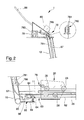
- figure 2 is a side elevation view, on an enlarged scale, of figure 1, with some parts removed for the sake of clarity;
- figure 3 is a side elevation view of a portion extracted from figure 1 on an enlarged scale and in a second operative position;
- figure 4 is a side elevation view of a second preferred embodiment of the machine in figure 1 with some parts removed for the sake of clarity.
- In figure 1, number 1 indicates, in its entirety, a gymnastic machine for the performance of muscle stretching exercises. This machine 1 comprises a
frame 10 supporting asupport member 20 by means of aguide 21 so constructed that thesupport member 20 is movable along a given direction D from and to astarting station 30. It must be noted that the following description is provided with reference to the lower limbs of a user. For the sake of completeness, it should be noted that theguide 21 is provided with twolongitudinal members 26 supported by acentral beam 11 on theframe 10, and that thesupport member 20 is carried by themembers 26 in a freely longitudinally sliding manner by means of the interposition of a plurality ofrollers 28 that hold bilaterally thesupport member 20 engaged on theguide 21. In view of the above description, thesupport member 20 can be interpreted as a slide that, for sake of simplicity, will be indicated, in the following, by thesame number 20. - With reference to the attached drawings, the
starting station 30 is designed to house a first lower limb, which may be either one of a pair of limbs, and theslide 20 is shaped to provide support for the second lower limb, so as to guide such second limb along the direction D and enable, in use, to control a scissor movement of the second limb in relation to the first limb, which is retained in thestarting station 30. As shall be readily apparent hereafter, means are provided to prevent straining of the lower limb muscles and to make it safe to perform muscle stretching exercises. - Again with reference to figure 1, the
station 30 comprises aunit 32 designed to house stably the first limb, and it is provided with arest 12 carried rigidly by a central upright 17 forming part of theframe 10 and comprising acushion 14 for the upper part of the user's body. If necessary, saidrest 12 may comprise ahandlebar 16, as shown in figure 1, wherein said handlebar is ring-shaped simply for reasons of practicality and safety. - With reference to figure 1, and with particular reference to figures 3 and 4, the machine 1 comprises a controlling device, associated with the
slide 20 and suitable for controlling, in use, the rotation of the limb carried by theslide 20 with respect to the given direction D during the performance of the scissor movement, as described in more detail later on. - It must be noted that the
unit 32, designed to house stably the first limb, is shaped so as to induce and maintain the flexion of such limb In this regard, theunit 32 comprises a retaining member 34, which can be selectively disengaged, for holding a joint of the first limb. In particular, said retaining member 34 comprises a cushion 36 for the posterior part of the leg of the first limb. This cushion 36 is hinged to theframe 10 around a substantiallyvertical axis 37 so that it is switchable between a position of use, shown in figure 1, wherein it lies transverse to the direction D, and a neutral position, rotated through about 90° with respect to the first position. For the sake of clarity, when the cushion 36 occupies the respective position for use, it provides support for the user's first lower limb and enables the user to keep the limb flexed without effort, with the knee joint kept bent at an approximately 90° angle. On the other hand, when the cushion 36 occupies its respective neutral position, user wishing to perform the scissor movement must exert an adequate muscular effort to keep his/her first lower limbs within thestarting station 30 without the aid of auxiliary means. - With particular reference to figure 3, the
slide 20 comprises a baseanterior portion 22 that is shaped in such a given way as to support at least a portion of the second lower limb placed between the knee and the foot. Furthermore, theslide 20 comprises aposterior portion 24 for resting the neck of the foot of said second limb. For the sake of convenience, here and on the following pages, saidposterior portion 24 may be mentioned using the expressiontibial cushion 24. Furthermore, saidanterior portion 22 is associated with a regulatingunit 50 suitable for varying the position of the portion with respect to theframe 10, and consequently for changing the angle of the leg of the second limb with respect to saidframe 10. In particular, said regulatingunit 50 comprises a first regulatingdevice 52 for adjusting the starting position/the reference position of theportion 22/of thetibial cushion 24 with respect to the direction D/to theframe 10, and a secondregulating device 54 suitable for changing, in use, the inclination of theportion 22/of thetibial cushion 24 with respect to the direction D/to theframe 10, and particularly around anaxle 55 integral with theslide 20, in relation to the current distance between theslide 20 and thestation 30. - The second regulating
device 54 comprises aroller tappet 56 carried by theslide 20 and ashaped member 58 delimited by aprofile 59 that is suitable for controlling the rotation of theportion 22/of thetibial cushion 24 with respect to the direction D/to theframe 10. The weight of the user performing the exercise ensures that a rolling contact is constantly maintained between theroller tappet 56 and theshaped member 58, without any need to include a spring return component to guarantee the proper operation of the second regulatingdevice 54. - It must be noted that the
profile 59 is shaped like aplane 59 decreasing towards thestarting station 30. The rotation of thetibial cushion 24 thus increases in a substantially linear fashion. However, where it is deemed advisable, it may be advantageous to shape theprofile 59 differently in order to impose different variations in the inclination of theportion 22/of thetibial cushion 24 with respect to theframe 10/to the direction D as the slide moves from and to thestation 30. - Again with reference to figure 3, the first regulating
device 52 comprises asupport member 53 for theroller tappet 56 that is adjustable in at least two positions, to determine reference inclinations/starting inclinations of theportion 22/of thetibial cushion 24 with respect to the given direction D/to theframe 10. In particular, themember 53 comprises alever 53 carried rotatable by theslide 20 with respect to anaxle 51 parallel to theaxle 55, and which can be locked in a given position by alocking device 501. In this regard, saidlocking device 501 comprises apin 503 snap fitted prismatic to asupport 504 by means of the thrust of aspring 505 contained inside asupport member 504, which can be switched by alever 509 connected to thepin 503 by means of a connectingmember 507. Saidpin 503 faces ahead 531 that is carried by thelever 53 at opposite side with respect to therespective wheel 532, in such a way as to engage aradial hole 533 from a plurality ofradial holes 533 provided in thehead 531, each of which coincides with a starting inclination of theportion 22/of thetibial cushion 24 with respect to the direction D. In view of the above description, the regulatingdevice 52 enables to define starting inclinations of thetibial cushion 24. - With particular reference to figure 2, the machine 1 comprises a
braking device 60 suitable for controlling the position of theslide 20 with respect to thestarting station 30 in order to prevent straining of the musculature of the lower limbs. Thebraking device 60 comprises anelongated member 62, which is rigidly connected to theslide 20 and carried parallel to the given direction D between a pair ofjaws 64, at least one of which is movable transversally to the direction D against the force of a spring to switch thebraking device 60 from a respective active position to a respective inactive position, which permits the operation of theslide 20 and its consequent displacement from and to thestation 30. It must be noted that theelongated member 62 comprises afoil 62 wound in a ring around twotransmission elements 68 carried by theframe 10 at the ends of theelongated members 26; it must be also noted that thefoil 62 is connected to theslide 20 by means of the respective ends; and that the saidfoil 62 is provided with abraking branch 63 positioned between thejaws 64 in order to be alternately locked in place or left free to move with respect to thejaws 64. - In this regard, the
device 60 comprises a manually-operatedmember 66 carried by theframe 10 for controlling the movement of at least one of thejaws 64 in relation to the other from and to a respective locking position, wherein theelongated member 62 is normally held locked by the pair ofjaws 64 so as to prevent any movement of theslide 20 along the given direction D. This manually-operatedmember 66 comprises alever 66 hinged to theframe 10 and interfaced with thelower jaw 64 by means of alever 65, which can be actuated by means of a Bowdencable 67 connected to thelever 66. Clearly, the presence of aspring 69 acting on thelower jaw 64 allows to define the normal locked situation of thefoil 62 and consequently also of theslide 20, and thus enables the second limb to perform scissor movement with respect to the first limb in safety because, when thelever 66 is released, theslide 20 is locked in its respective current position. - Again with reference to figure 2, the machine 1 comprises a measuring
device 70 for measuring the position of theslide 20 with respect to the startingstation 30; this device is suitable for providing information about the progress of the muscle stretching, able to give significant data on the effectiveness of the training session, or series of successive training sessions. - The measuring
device 70 is analogical and comprises atape measure 78 with atape 781 presenting a graduatedscale 782 and wound in a spiral inside abox 783. Thetape 781 presents one end 785 connected to theslide 20 to enable a measurement of the latter's current position with respect to the startingstation 30. In this regard, thetape 781 is wound around a pair ofpulleys 786 supported by theframe 10 to define a given path between the rest 12 and theslide 20 so as to facilitate the user's reading of the graduatedscale 782 during the training session. It must be noted that thetape 781 is associated with a spring return component, known and therefore not shown, inside thebox 783, and that thetape 781 internally engages at least a portion of theupright 17, which serves as a safety casing. It must be noted that the employment of a tape measure on a machine for muscle training is in itself new and original, and enables a simple and cost-effective monitoring of the user's muscle stretching progress. As it is well known, muscle stretching exercises are all the more effective the longer the elongated position is maintained, and an indicator of the effectiveness of the training is represented by the time interval during which said position can be maintained. Therefore, the machine 1 has been provided with atimer device 80 of known type suitable for timing the duration of an exercise, or of the time interval during which theslide 20 is held in a given position with respect to the startingstation 30 by means of thejaws 64. - From the above description, it is clear that, providing the
braking device 60 has been disengaged, theslide 20 is free to move from and to thestation 30. Therefore, actuating theslide 20 along therespective guide 21, and the consequent performance of the scissor movement is readily achievable simply by exploiting the gravity associated with the weight of the user performing the exercises, and particularly with the part of the user's weight coming to bear on the second lower limb, i.e. the limb that comes to bear on theslide 20. - In addition, the training method that can be implemented on a machine 1 as described above is easily understood from the above description and requires no further explanation.
- It is worth noting, however, that such method comprises the steps of: positioning stably a first limb in the starting
station 30 situated in front of the user performing the exercise, with his/her knee bent and the posterior portion of the first limb resting on the front portion of the cushion 36; resting the knee and the tibia of the second limb on thebase portion 22 of theslide 20, and the neck of the foot on thetibial cushion 24; actuating theslide 20 with respect to said startingstation 30; and controlling, in use, a scissor movement of said second limb by means of abraking device 60. It must be noted that the step of actuating theslide 20 with respect to the startingstation 30 and the step of controlling, in use, the scissor movement of said second limb by means of thebraking device 60 may take place simultaneously. - Finally, it is clear that modifications and variants can be made to the gymnastic machine 1 described and illustrated herein without however departing from the protective scope of the present invention.
- For instance, as already explained with reference to the
Italian patent application no. RA2006A000009 slide 20 on theguide 21 by means of an actuating device, possibly operated on the basis of cycles programmed by a trainer to suit a given user's specific needs. This opportunity may be particularly useful in the case of users particularly out of condition, or with little experience of performing physical exercises on their own. For the sake of practicality and given the analogy, reference should be made to the corresponding part of the application '009, the teachings of which are considered an integral part of the present application for the sake of brevity. - Moreover, according to a further embodiment represented in figure 4, the measuring
device 70 may be constructed using a device of the digital type. Said measuringdevice 70 comprises a transducer 71 provided with arigid reference element 72 integrally connected to theframe 10, and particularly to theguide 21, and with amovable element 74 connected directly or indirectly to theslide 20. Furthermore, the measuringdevice 70 comprises a calculatingdevice 76 for calculating the relative position between themovable element 74 and therigid element 72 in order to generate data to indicate the instantaneous position of saidslide 20 with respect to the startingstation 30. Said transducer 71 could validly comprise an encoder that is indicated by the same reference number for the sake of convenience. In the case in point, the encoder 71 is of the linear type and the respectivemovable element 74 comprises a magnetic band associated with thefoil 62 and indicated, again for convenience, by thesame number 74. - The calculating
device 76 can be carried on board theslide 20, and so can themovable element 74, but it could also be carried by theframe 10 in any other position, if arranged so as to exchange remote data with themovable element 74. - Alternatively, the encoder 71 could be of the rotating type and be associated with one of the transmission pulleys 68.
- In view of the above description, the machine 1, described with reference to the accompanying drawings, punctually solves the technical problems set out above and its use is easy and safe even for users who are inexperienced in muscle stretching, so that it is useful in the prevention of muscle pains in the lumbar region.
Claims (57)
- A gymnastic machine (1) comprising a frame (10), a slide (20) carried movable by said frame (10) along a given direction (D) from and to a starting station (30); characterised in that said slide (20) is suitable for coupling with a first limb in such a way as to guide it along said given direction (D) and to enable, in use, to control a scissor movement of the first limb with respect to a second limb retained at the starting station (30).
- A machine according to claim 1, characterised in that said first limb comprises a first lower limb and that said second limb comprises a second lower limb distinguished from said first lower limb.
- A machine according to claim 1 or 2, characterised in that said starting station (30) comprises housing means (32) for housing stably said second limb, and that said frame (10) comprises a rigid rest (12) associated with said starting station (30).
- A machine according to claim 1 or 2 or 3, characterised in that said slide comprises a support member (22) for said first limb; controlling means (50) for regulating the inclination of said slide (20) being associated with said support member (22) so as to control, in use, the rotation of said first limb during said scissor movement.
- A machine according to claim 4, characterised in that said controlling means (50) comprise regulating means (50) for adjusting the position of said support member (22) with respect to said frame (10).
- A machine according to claim 5, characterised in that said regulating means (50) comprise a first regulating device (52) for adjusting the starting position of said support member (22) with respect to said frame (10).
- A machine according to claim 4 or 5, characterised in that said regulating means (50) comprise a second regulating device (54) suitable for varying the inclination, in use, of said support member (22) with respect to said frame (10) in relation to the current distance of said slide (20) with respect to said starting station (30).
- A machine according to claim 7, characterised in that said second regulating device (54) comprises a roller tappet (56) carried by said slide (20) and a shaped member (58) delimited by a profile (59) suitable for controlling the rotation of said support member (22) with respect to said frame (10).
- A machine according to claim 8, characterised in that said profile (59) is shaped like a plane (59) decreasing towards said starting station (30).
- A machine according to claim 7 or 8, characterised in that said first regulating device (52) comprises a support (53) for said roller tappet (56) that is adjustable in at least two positions in order to determine reference inclinations/starting inclinations of said support member (22) with respect to said given direction (D).
- A machine according to any one of claims 3-10, characterised in that said housing means (32) for said second limb are shaped so as to induce and maintain the flexion of the limb around said rest (12).
- A machine according to any one of claims 3-11, characterised in that said housing means (32) comprise a retaining member (34) that can be selectively disengaged for holding a joint of said second limb.
- A machine according to claim 12, characterised in that said retaining member (34) is carried movable by said frame (10) by means of a respective upright (17) so that it can be selectively disengaged.
- A machine according to claim 12 or 13, characterised in that said retaining member (34) comprises at least a first cushion (36) for the reference of said second limb.
- A machine according to any one of claims 4-11, characterised in that said support member (22) presents an anterior portion (22) shaped so as to provide support for a knee of said first limb and a posterior portion (24) comprising a tibial cushion (24), suitable for supporting the neck of the foot of said first limb.
- A machine according to any one of the preceding claims, characterised by comprising controlling means (50) for controlling the position of said slide (20) with respect to said starting station (30) in order to prevent any straining of the musculature of the lower limbs.
- A machine according to claim 16, characterised in that said controlling means (50) for controlling the position of said slide (20) comprise a braking device (60) normally engaged and selectively switchable to be disengaged, and thereby enable, in use, the alternate locking and release of the movement of said slide (20) from and to said starting station (30).
- A machine according to claim 17, characterised in that said braking device (60) comprises an elongated member (62) rigidly connected to said slide (20) and carried parallel to said given direction (D) between a pair of jaws (64), at least one of which is movable transversally to said direction (D) against the force of a spring in order to inactivate said braking device and enable the actuation of said slide (20).
- A machine according to claim 18, characterised in that said braking device (60) comprises a manually-operated member (66) carried by said frame (10) for controlling the movement of at least one of said jaws (64) from and to a respective locking position wherein said elongated member (62) is firmly held by said pair of jaws (64) so as to prevent any movement of said slide (20) along said given direction (D).
- A machine according to claim 18 or 19, characterised in that said elongated member (62) comprises a foil (62) wound in a ring around two transmission elements (68) carried by said frame (10); said foil (62) being connected to said slide (20) by means of respective ends and being provided with a braking branch (63) that engages a space delimited by said jaws (64) in order to be alternately locked in place or left free to move with respect to said jaws (64).
- A machine according to any one of the preceding claims, characterised by comprising measuring means (70) for measuring the position of said slide (20) with respect to the said starting station (30).
- A machine according to claim 21, characterised in that said measuring means (70) comprise a transducer (71) provided with a rigid reference element (72) integrally connected to the frame (10), and with a movable element (74) connected directly or indirectly to said slide (20), and with a calculating device (76) for calculating the relative position between said movable element (74) and said rigid element (72) in order to generate data to indicate the instantaneous position of said slide (20) with respect to said starting station (30).
- A machine according to claim 22, characterised in that said movable element (74) is enabled to exchange remotely data with said calculating device (76).
- A machine according to claim 22 or 23, characterised in that said transducer (71) comprises an encoder (71).
- A machine according to claim 24, characterised in that said encoder (71) is of the linear type and that said respective movable element (74) is associated with said foil (62).
- A machine according to claim 24, characterised in that at least one of said transmission elements (68) comprises a pulley (68), that said encoder (71) is of the rotating type and that said respective movable element (74) is associated with said pulley (68).
- A machine according to claim 21, characterised in that said measuring means (70) comprise an analogical measuring device (78) connected to said slide (20) and calibrated so as to identify the current position of the slide (20) itself with respect to said starting station (30).
- A machine according to claim 27, characterised in that said measuring device (78) comprises a metal tape measure (78) provided with one end (79) connected to said slide (20), which can be unwound against a spring return mechanism and which is at least partially protected by a casing (17) for safety reasons.
- A machine according to claim 28, characterised in that said casing (17) is associated with said frame (10).
- A machine according to claim 29, characterised in that said tape measure (78) comprises a tape (781) provided with a graduated scale (782) wound in a spiral inside a box (783); said tape(781) being provided with one end (785) connected to said slide (20) to enable the latter's current position to be measured with respect to said starting station (30); said tape (781) being wound around a plurality of pulleys (786) supported by said frame (10) in order to define a given path so as to facilitate the user's reading of said graduated scale (782) during the training session.
- A machine according to any one of claims 17-20 or according to any one of claims 21-30 depending on any one of claims 17-20, characterised by comprising timer means (80) for timing the duration of an exercise or of the time interval during which said slide (20) is held locked with respect to said starting station (30) by means of said braking device (60).
- A machine according to any one of claims 4-31, characterised in that said rest (12) comprises a second cushion (14) for the upper part of the user's body.
- A machine according to any one of claims 4-32, characterised in that said rest (12) comprises a handle (16) suitable for frontal gripping.
- A machine according to any one of the preceding claims, characterised by comprising actuating means for actuating said slide (20) with respect to said starting station (30).
- A machine according to claim 34, characterised in that said actuating means comprise, in use, the action of gravity on said first limb.
- A machine according to any one of the preceding claims, characterised in that said slide (20) is carried by a guide (21) of the rectilinear motion provided with at least two elongated members (26); said slide (20) being supported bilaterally by means of the interposition of a plurality of rollers (28).
- A training method to be implemented on a machine (1) described with reference to any one of the preceding claims, said method being characterized by comprising the step of stably positioning a second limb in a starting station (30); the step of associating a first limb with a slide (20) carried movable by a frame (10) along a given direction (D) from and to said starting station (30); the step of actuating said slide (20) with respect to said starting station (30) and the step of controlling, in use, a scissor movement of said first limb across said second limb.
- A method according to claim 37, characterised in that said first and second limbs may be either one of a pair of limbs.
- A method according to claim 37 or 38, characterised by comprising a step of resting (12) a region of the body on a rest (12) carried by said frame at said starting station (30).
- A method according to any one of claims 37-39, characterised by comprising the step of causing, in use, a rotation of said first limb during said scissor movement; said step of causing a rotation of said first limb being associated to the step of maintaining said second limb flexed in said starting station (30).
- A method according to claim 39, characterised in that said step of maintaining said second limbs flexed in said starting station (30) comprises the step of retaining said second limb in said starting station (30) by means of a first cushion (36) for resting a posterior portion of said second limb.
- A method according to any one of claims 37-41, characterised in that said first and second limbs comprise a respective first and second lower limbs of a user; said slide (20) being shaped in such a manner as to be coupled with said first lower limb.
- A method according to claim 42, characterised in that said step of associating a first limb with said slide (20) comprises the step of resting the knee of said first limb on a base portion of said slide (20) and the step of resting the respective neck of the foot on a tibial cushion (24) of said slide (20).
- A method according to claim 43, characterised by comprising the step of regulating the position of said tibial cushion (24) with respect to said frame (10).
- A method according to claim 44, characterised in that said step of regulating the position of said tibial cushion (24) comprises a first step of regulating the starting position of said tibial cushion (24) with respect to said given direction (D) by means of a first regulating device (52), and a second step of regulating, in use, the inclination of said tibial cushion (24) with respect to said frame in relation to the distance of said slide (20) from said starting station (30) by means of a second regulating device (54).
- A method according to claim 45, characterised in that said second step of regulating, in use, the inclination of said tibial cushion (24) with respect to said frame comprises the step of rotating said tibial cushion (24) with respect to said given direction (D) by means of a roller tappet (56) carried by said slide (20) and a shaped element (58) with a sloping plane carried by said frame (10).
- A method according to any one of claims 37-46, characterised in that the step of actuating said slide (20) with respect to said starting station (30) is associated with the step of controlling, in use, the amplitude of said scissor movement of said first limb across said second limb in order to prevent any straining of the musculature of the lower limbs.
- A method according to claim 47, characterised in that said step of controlling, in use, said scissor movement comprises the step of interacting with a braking device (60).
- A method according to claim 48, characterised in that said step of interacting with a braking device (60) comprises the step of acting by means of a pair of jaws (64) on a braking branch (63) of a foil (62) connected in a ring to said slide (20); at least one of said jaws (64) being movable transversally to said direction (D) against the force of a spring in order to inactivate said braking device (60).
- A method according to claim 49, characterised in that said step of acting on the braking branch (63) of said foil (62) is achievable manually.
- A method according to any one of claims 37-50, characterised in that said step of actuating said slide (20) with respect to said starting station (30) comprises the step of displacing said slide (20) exclusively by means of the gravity coming to bear on said slide (20).
- A method according to any one of claims 37-51, characterised by comprising the step of measuring the position of said slide (20) with respect to said starting station (30) by means of a measuring device (70).
- A method according to claim 52, characterised in that the step of measuring the position of said slide (20) with respect to said starting station (30) is achievable by means of an analogical measuring device connected to said slide (20) and calibrated so as to identify the current position of said slide (20) with respect to said starting station (30).
- A method according to claim 52, characterised in that said step of measuring the position of said slide (20) with respect to said starting station (30) is achievable by means of a digital measuring device connected to said slide (20) and calibrated so as to identify the current position of said slide (20) with respect to said starting station (30).
- A method according to any one of claims 37-54, characterised in that said step of actuating said slide (20) with respect to said starting station (30) is associated with the step of calculating the duration of an exercise, or of a time interval during which said slide (20) is held in a stable position with respect to said starting station (30).
- A method according to any one of claims 48-54, characterised in that said actuating means comprise the action of gravity on the said first limb.
- The use of a tape measure in a gymnastic machine for muscle stretching, as described with reference to the claims 1-36, said tape measure (78) comprising a tape (781) provided with a graduated scale (782) wound in a spiral inside a box (783); said tape (781) being provided with one end (785) connected to said slide 20 to enable the measurement of the latter's current position with respect to said starting station (30); said tape (781) being wound round a plurality of pulleys (786) supported by said frame (10) to define a given path so as to facilitate the user's reading of said graduated scale (782) during the training session.
Applications Claiming Priority (1)
| Application Number | Priority Date | Filing Date | Title |
|---|---|---|---|
| IT000012A ITRA20060012A1 (en) | 2006-02-24 | 2006-02-24 | GINNICA MACHINE. |
Publications (2)
| Publication Number | Publication Date |
|---|---|
| EP1825887A1 true EP1825887A1 (en) | 2007-08-29 |
| EP1825887B1 EP1825887B1 (en) | 2010-12-01 |
Family
ID=38055652
Family Applications (1)
| Application Number | Title | Priority Date | Filing Date |
|---|---|---|---|
| EP07102592A Active EP1825887B1 (en) | 2006-02-24 | 2007-02-16 | Gymnastic machine |
Country Status (6)
| Country | Link |
|---|---|
| US (1) | US7878951B2 (en) |
| EP (1) | EP1825887B1 (en) |
| CN (1) | CN101024114B (en) |
| AT (1) | ATE490007T1 (en) |
| DE (1) | DE602007010847D1 (en) |
| IT (1) | ITRA20060012A1 (en) |
Families Citing this family (21)
| Publication number | Priority date | Publication date | Assignee | Title |
|---|---|---|---|---|
| US7740563B2 (en) | 2004-08-11 | 2010-06-22 | Icon Ip, Inc. | Elliptical exercise machine with integrated anaerobic exercise system |
| US7766797B2 (en) | 2004-08-11 | 2010-08-03 | Icon Ip, Inc. | Breakaway or folding elliptical exercise machine |
| US7717828B2 (en) | 2006-08-02 | 2010-05-18 | Icon Ip, Inc. | Exercise device with pivoting assembly |
| US7658698B2 (en) | 2006-08-02 | 2010-02-09 | Icon Ip, Inc. | Variable stride exercise device with ramp |
| US7736279B2 (en) | 2007-02-20 | 2010-06-15 | Icon Ip, Inc. | One-step foldable elliptical exercise machine |
| US7674205B2 (en) | 2007-05-08 | 2010-03-09 | Icon Ip, Inc. | Elliptical exercise machine with adjustable foot motion |
| US7618350B2 (en) | 2007-06-04 | 2009-11-17 | Icon Ip, Inc. | Elliptical exercise machine with adjustable ramp |
| US8430800B2 (en) * | 2008-02-07 | 2013-04-30 | Gregory Joseph Nolan | Leg exercise machine |
| WO2010107632A1 (en) | 2009-03-17 | 2010-09-23 | Woodway Usa, Inc. | Power generating manually operated treadmill |
| USD611999S1 (en) * | 2009-06-29 | 2010-03-16 | Johnson Health Tech Co., Ltd. | Exercise apparatus |
| US8992391B2 (en) * | 2010-09-17 | 2015-03-31 | Seastrom Manufacturing Co., Inc. | Sizing fit cycle |
| TWM408386U (en) * | 2010-11-02 | 2011-08-01 | Zhu Zhen Gang | Foot-treading stretch machine |
| US9358419B1 (en) | 2013-03-15 | 2016-06-07 | Jonathan Smith | Physical fitness device |
| WO2017062504A1 (en) | 2015-10-06 | 2017-04-13 | Woodway Usa, Inc. | Manual treadmill and methods of operating the same |
| US10625137B2 (en) | 2016-03-18 | 2020-04-21 | Icon Health & Fitness, Inc. | Coordinated displays in an exercise device |
| US10493349B2 (en) | 2016-03-18 | 2019-12-03 | Icon Health & Fitness, Inc. | Display on exercise device |
| WO2018006055A1 (en) | 2016-07-01 | 2018-01-04 | Woodway Usa, Inc. | Motorized treadmill with motor braking mechanism and methods of operating same |
| US10625114B2 (en) | 2016-11-01 | 2020-04-21 | Icon Health & Fitness, Inc. | Elliptical and stationary bicycle apparatus including row functionality |
| USD930089S1 (en) | 2019-03-12 | 2021-09-07 | Woodway Usa, Inc. | Treadmill |
| US11278764B1 (en) * | 2020-12-28 | 2022-03-22 | Ned Falk | Elbow and wrist stretching device |
| CN114558282B (en) * | 2022-04-11 | 2023-03-10 | 吉林医药学院附属医院 | Hemiplegia fitness equipment for rehabilitation medical science department |
Citations (5)
| Publication number | Priority date | Publication date | Assignee | Title |
|---|---|---|---|---|
| US4046373A (en) * | 1975-11-12 | 1977-09-06 | Chong Chan Kim | Multi-purpose parallel bar exercising apparatus |
| US4826158A (en) * | 1988-02-01 | 1989-05-02 | Fields Jr Thomas H | Body stretching and exercising device |
| DE20006846U1 (en) * | 2000-04-13 | 2000-11-02 | Brylka, Theophil, Dr., 68775 Ketsch | Training device for stretching the muscles of the hip flexor and hip extensor |
| WO2001045801A1 (en) * | 1999-12-21 | 2001-06-28 | Tyne Philip J | Lunge exercice device |
| ES2182620A1 (en) * | 1999-12-17 | 2003-03-01 | Menendez Miguel Angel Menendez | Leg stretching device |
Family Cites Families (5)
| Publication number | Priority date | Publication date | Assignee | Title |
|---|---|---|---|---|
| JPH03165744A (en) * | 1989-11-22 | 1991-07-17 | Konbi Kk | Instantaneous force measuring device by leg extending force |
| US5263919A (en) * | 1992-11-12 | 1993-11-23 | Hollenback George M | Single leg squat machine |
| CN2179172Y (en) | 1993-12-10 | 1994-10-12 | 罗美捷 | fitness chair |
| US6368254B1 (en) * | 1999-10-14 | 2002-04-09 | Robert A. Wall | Hybrid stretching and exercising machine |
| WO2005044393A1 (en) * | 2003-11-03 | 2005-05-19 | Tommy Bull | Stretching and exercise apparatus |
-
2006
- 2006-02-24 IT IT000012A patent/ITRA20060012A1/en unknown
-
2007
- 2007-02-16 EP EP07102592A patent/EP1825887B1/en active Active
- 2007-02-16 US US11/708,154 patent/US7878951B2/en active Active
- 2007-02-16 AT AT07102592T patent/ATE490007T1/en not_active IP Right Cessation
- 2007-02-16 DE DE602007010847T patent/DE602007010847D1/en active Active
- 2007-02-25 CN CN2007100858224A patent/CN101024114B/en active Active
Patent Citations (5)
| Publication number | Priority date | Publication date | Assignee | Title |
|---|---|---|---|---|
| US4046373A (en) * | 1975-11-12 | 1977-09-06 | Chong Chan Kim | Multi-purpose parallel bar exercising apparatus |
| US4826158A (en) * | 1988-02-01 | 1989-05-02 | Fields Jr Thomas H | Body stretching and exercising device |
| ES2182620A1 (en) * | 1999-12-17 | 2003-03-01 | Menendez Miguel Angel Menendez | Leg stretching device |
| WO2001045801A1 (en) * | 1999-12-21 | 2001-06-28 | Tyne Philip J | Lunge exercice device |
| DE20006846U1 (en) * | 2000-04-13 | 2000-11-02 | Brylka, Theophil, Dr., 68775 Ketsch | Training device for stretching the muscles of the hip flexor and hip extensor |
Also Published As
| Publication number | Publication date |
|---|---|
| DE602007010847D1 (en) | 2011-01-13 |
| US20070202995A1 (en) | 2007-08-30 |
| ITRA20060012A1 (en) | 2007-08-25 |
| EP1825887B1 (en) | 2010-12-01 |
| CN101024114A (en) | 2007-08-29 |
| CN101024114B (en) | 2012-10-24 |
| US7878951B2 (en) | 2011-02-01 |
| ATE490007T1 (en) | 2010-12-15 |
Similar Documents
| Publication | Publication Date | Title |
|---|---|---|
| EP1825887A1 (en) | Gymnastic machine | |
| US7867153B2 (en) | Gymnastic machine | |
| US7854685B2 (en) | Training system and method | |
| US5624353A (en) | Dynamically controlled resistance exercise machine | |
| US5964684A (en) | Exercise method and apparatus | |
| CN108883333B (en) | Rehabilitation device and its use for exercising the shoulder region | |
| US20140011645A1 (en) | Multiple position exercise device | |
| WO2008066559A2 (en) | Abdominal exercise device | |
| KR101953236B1 (en) | Rehabilitation Equipment for Hemiplegic Lower Limb | |
| ES2643220T3 (en) | Machine for gymnastic exercises, particularly for muscle stretching | |
| EP3124085B1 (en) | Machine for training the hamstring muscles | |
| US6814708B1 (en) | Body stretching apparatus and method | |
| US20110137215A1 (en) | Apparatus and Method for Knee Rehabilitation | |
| US20070105695A1 (en) | Exercise apparatus for exercising lower limbs | |
| CN108883332B (en) | Rehabilitation device and its use for exercising the shoulder region | |
| CN110868982A (en) | Walking training device for treatment | |
| JP2008520338A (en) | Rotary rehabilitation apparatus and method | |
| NL2015675B1 (en) | Training module. | |
| US5725462A (en) | Reciprocal inhibition exercise device | |
| RU2417066C2 (en) | Spinal traction apparatus and method of application thereof | |
| US20130045839A1 (en) | Sitting type stepper | |
| KR102252959B1 (en) | Multi-function sporting equipment | |
| US7648445B1 (en) | Elliptical exercise apparatus | |
| WO2012108422A1 (en) | Rotation angle measurement device, rotation angle measurement method, pivot foot measurement method, training device, and training method | |
| KR200338175Y1 (en) | Lower body exercise equipment |
Legal Events
| Date | Code | Title | Description |
|---|---|---|---|
| PUAI | Public reference made under article 153(3) epc to a published international application that has entered the european phase |
Free format text: ORIGINAL CODE: 0009012 |
|
| AK | Designated contracting states |
Kind code of ref document: A1 Designated state(s): AT BE BG CH CY CZ DE DK EE ES FI FR GB GR HU IE IS IT LI LT LU LV MC NL PL PT RO SE SI SK TR |
|
| AX | Request for extension of the european patent |
Extension state: AL BA HR MK YU |
|
| 17P | Request for examination filed |
Effective date: 20080229 |
|
| AKX | Designation fees paid |
Designated state(s): AT BE BG CH CY CZ DE DK EE ES FI FR GB GR HU IE IS IT LI LT LU LV MC NL PL PT RO SE SI SK TR |
|
| GRAP | Despatch of communication of intention to grant a patent |
Free format text: ORIGINAL CODE: EPIDOSNIGR1 |
|
| GRAS | Grant fee paid |
Free format text: ORIGINAL CODE: EPIDOSNIGR3 |
|
| GRAA | (expected) grant |
Free format text: ORIGINAL CODE: 0009210 |
|
| AK | Designated contracting states |
Kind code of ref document: B1 Designated state(s): AT BE BG CH CY CZ DE DK EE ES FI FR GB GR HU IE IS IT LI LT LU LV MC NL PL PT RO SE SI SK TR |
|
| REG | Reference to a national code |
Ref country code: GB Ref legal event code: FG4D |
|
| REG | Reference to a national code |
Ref country code: CH Ref legal event code: EP |
|
| REG | Reference to a national code |
Ref country code: IE Ref legal event code: FG4D |
|
| REF | Corresponds to: |
Ref document number: 602007010847 Country of ref document: DE Date of ref document: 20110113 Kind code of ref document: P |
|
| REG | Reference to a national code |
Ref country code: NL Ref legal event code: T3 |
|
| PG25 | Lapsed in a contracting state [announced via postgrant information from national office to epo] |
Ref country code: LT Free format text: LAPSE BECAUSE OF FAILURE TO SUBMIT A TRANSLATION OF THE DESCRIPTION OR TO PAY THE FEE WITHIN THE PRESCRIBED TIME-LIMIT Effective date: 20101201 |
|
| LTIE | Lt: invalidation of european patent or patent extension |
Effective date: 20101201 |
|
| PG25 | Lapsed in a contracting state [announced via postgrant information from national office to epo] |
Ref country code: SI Free format text: LAPSE BECAUSE OF FAILURE TO SUBMIT A TRANSLATION OF THE DESCRIPTION OR TO PAY THE FEE WITHIN THE PRESCRIBED TIME-LIMIT Effective date: 20101201 Ref country code: BG Free format text: LAPSE BECAUSE OF FAILURE TO SUBMIT A TRANSLATION OF THE DESCRIPTION OR TO PAY THE FEE WITHIN THE PRESCRIBED TIME-LIMIT Effective date: 20110301 Ref country code: SE Free format text: LAPSE BECAUSE OF FAILURE TO SUBMIT A TRANSLATION OF THE DESCRIPTION OR TO PAY THE FEE WITHIN THE PRESCRIBED TIME-LIMIT Effective date: 20101201 Ref country code: CY Free format text: LAPSE BECAUSE OF FAILURE TO SUBMIT A TRANSLATION OF THE DESCRIPTION OR TO PAY THE FEE WITHIN THE PRESCRIBED TIME-LIMIT Effective date: 20101201 Ref country code: LV Free format text: LAPSE BECAUSE OF FAILURE TO SUBMIT A TRANSLATION OF THE DESCRIPTION OR TO PAY THE FEE WITHIN THE PRESCRIBED TIME-LIMIT Effective date: 20101201 Ref country code: AT Free format text: LAPSE BECAUSE OF FAILURE TO SUBMIT A TRANSLATION OF THE DESCRIPTION OR TO PAY THE FEE WITHIN THE PRESCRIBED TIME-LIMIT Effective date: 20101201 Ref country code: FI Free format text: LAPSE BECAUSE OF FAILURE TO SUBMIT A TRANSLATION OF THE DESCRIPTION OR TO PAY THE FEE WITHIN THE PRESCRIBED TIME-LIMIT Effective date: 20101201 |
|
| PG25 | Lapsed in a contracting state [announced via postgrant information from national office to epo] |
Ref country code: GR Free format text: LAPSE BECAUSE OF FAILURE TO SUBMIT A TRANSLATION OF THE DESCRIPTION OR TO PAY THE FEE WITHIN THE PRESCRIBED TIME-LIMIT Effective date: 20110302 |
|
| PG25 | Lapsed in a contracting state [announced via postgrant information from national office to epo] |
Ref country code: IS Free format text: LAPSE BECAUSE OF FAILURE TO SUBMIT A TRANSLATION OF THE DESCRIPTION OR TO PAY THE FEE WITHIN THE PRESCRIBED TIME-LIMIT Effective date: 20110401 Ref country code: CZ Free format text: LAPSE BECAUSE OF FAILURE TO SUBMIT A TRANSLATION OF THE DESCRIPTION OR TO PAY THE FEE WITHIN THE PRESCRIBED TIME-LIMIT Effective date: 20101201 Ref country code: ES Free format text: LAPSE BECAUSE OF FAILURE TO SUBMIT A TRANSLATION OF THE DESCRIPTION OR TO PAY THE FEE WITHIN THE PRESCRIBED TIME-LIMIT Effective date: 20110312 Ref country code: EE Free format text: LAPSE BECAUSE OF FAILURE TO SUBMIT A TRANSLATION OF THE DESCRIPTION OR TO PAY THE FEE WITHIN THE PRESCRIBED TIME-LIMIT Effective date: 20101201 Ref country code: PT Free format text: LAPSE BECAUSE OF FAILURE TO SUBMIT A TRANSLATION OF THE DESCRIPTION OR TO PAY THE FEE WITHIN THE PRESCRIBED TIME-LIMIT Effective date: 20110401 Ref country code: BE Free format text: LAPSE BECAUSE OF FAILURE TO SUBMIT A TRANSLATION OF THE DESCRIPTION OR TO PAY THE FEE WITHIN THE PRESCRIBED TIME-LIMIT Effective date: 20101201 |
|
| PG25 | Lapsed in a contracting state [announced via postgrant information from national office to epo] |
Ref country code: PL Free format text: LAPSE BECAUSE OF FAILURE TO SUBMIT A TRANSLATION OF THE DESCRIPTION OR TO PAY THE FEE WITHIN THE PRESCRIBED TIME-LIMIT Effective date: 20101201 Ref country code: SK Free format text: LAPSE BECAUSE OF FAILURE TO SUBMIT A TRANSLATION OF THE DESCRIPTION OR TO PAY THE FEE WITHIN THE PRESCRIBED TIME-LIMIT Effective date: 20101201 Ref country code: RO Free format text: LAPSE BECAUSE OF FAILURE TO SUBMIT A TRANSLATION OF THE DESCRIPTION OR TO PAY THE FEE WITHIN THE PRESCRIBED TIME-LIMIT Effective date: 20101201 |
|
| PG25 | Lapsed in a contracting state [announced via postgrant information from national office to epo] |
Ref country code: MC Free format text: LAPSE BECAUSE OF NON-PAYMENT OF DUE FEES Effective date: 20110228 |
|
| REG | Reference to a national code |
Ref country code: CH Ref legal event code: PL |
|
| PLBE | No opposition filed within time limit |
Free format text: ORIGINAL CODE: 0009261 |
|
| STAA | Information on the status of an ep patent application or granted ep patent |
Free format text: STATUS: NO OPPOSITION FILED WITHIN TIME LIMIT |
|
| PG25 | Lapsed in a contracting state [announced via postgrant information from national office to epo] |
Ref country code: DK Free format text: LAPSE BECAUSE OF FAILURE TO SUBMIT A TRANSLATION OF THE DESCRIPTION OR TO PAY THE FEE WITHIN THE PRESCRIBED TIME-LIMIT Effective date: 20101201 Ref country code: CH Free format text: LAPSE BECAUSE OF NON-PAYMENT OF DUE FEES Effective date: 20110228 Ref country code: LI Free format text: LAPSE BECAUSE OF NON-PAYMENT OF DUE FEES Effective date: 20110228 |
|
| 26N | No opposition filed |
Effective date: 20110902 |
|
| REG | Reference to a national code |
Ref country code: FR Ref legal event code: ST Effective date: 20111102 |
|
| REG | Reference to a national code |
Ref country code: IE Ref legal event code: MM4A |
|
| REG | Reference to a national code |
Ref country code: DE Ref legal event code: R097 Ref document number: 602007010847 Country of ref document: DE Effective date: 20110902 |
|
| PG25 | Lapsed in a contracting state [announced via postgrant information from national office to epo] |
Ref country code: FR Free format text: LAPSE BECAUSE OF NON-PAYMENT OF DUE FEES Effective date: 20110228 Ref country code: IE Free format text: LAPSE BECAUSE OF NON-PAYMENT OF DUE FEES Effective date: 20110216 |
|
| PG25 | Lapsed in a contracting state [announced via postgrant information from national office to epo] |
Ref country code: LU Free format text: LAPSE BECAUSE OF NON-PAYMENT OF DUE FEES Effective date: 20110216 |
|
| PG25 | Lapsed in a contracting state [announced via postgrant information from national office to epo] |
Ref country code: TR Free format text: LAPSE BECAUSE OF FAILURE TO SUBMIT A TRANSLATION OF THE DESCRIPTION OR TO PAY THE FEE WITHIN THE PRESCRIBED TIME-LIMIT Effective date: 20101201 |
|
| PG25 | Lapsed in a contracting state [announced via postgrant information from national office to epo] |
Ref country code: HU Free format text: LAPSE BECAUSE OF FAILURE TO SUBMIT A TRANSLATION OF THE DESCRIPTION OR TO PAY THE FEE WITHIN THE PRESCRIBED TIME-LIMIT Effective date: 20101201 |
|
| P01 | Opt-out of the competence of the unified patent court (upc) registered |
Effective date: 20230530 |
|
| PGFP | Annual fee paid to national office [announced via postgrant information from national office to epo] |
Ref country code: NL Payment date: 20250224 Year of fee payment: 19 |
|
| PGFP | Annual fee paid to national office [announced via postgrant information from national office to epo] |
Ref country code: GB Payment date: 20250218 Year of fee payment: 19 |
|
| PGFP | Annual fee paid to national office [announced via postgrant information from national office to epo] |
Ref country code: DE Payment date: 20260220 Year of fee payment: 20 |
|
| PGFP | Annual fee paid to national office [announced via postgrant information from national office to epo] |
Ref country code: IT Payment date: 20260220 Year of fee payment: 20 |