EP1825612B1 - Method and apparatus for bias and alignment control in an optical signal transmitter - Google Patents
Method and apparatus for bias and alignment control in an optical signal transmitter Download PDFInfo
- Publication number
- EP1825612B1 EP1825612B1 EP05854014.7A EP05854014A EP1825612B1 EP 1825612 B1 EP1825612 B1 EP 1825612B1 EP 05854014 A EP05854014 A EP 05854014A EP 1825612 B1 EP1825612 B1 EP 1825612B1
- Authority
- EP
- European Patent Office
- Prior art keywords
- bias
- signal
- nrz
- output
- phase
- Prior art date
- Legal status (The legal status is an assumption and is not a legal conclusion. Google has not performed a legal analysis and makes no representation as to the accuracy of the status listed.)
- Expired - Lifetime
Links
Images




Classifications
-
- H—ELECTRICITY
- H04—ELECTRIC COMMUNICATION TECHNIQUE
- H04B—TRANSMISSION
- H04B10/00—Transmission systems employing electromagnetic waves other than radio-waves, e.g. infrared, visible or ultraviolet light, or employing corpuscular radiation, e.g. quantum communication
- H04B10/50—Transmitters
-
- H—ELECTRICITY
- H04—ELECTRIC COMMUNICATION TECHNIQUE
- H04B—TRANSMISSION
- H04B10/00—Transmission systems employing electromagnetic waves other than radio-waves, e.g. infrared, visible or ultraviolet light, or employing corpuscular radiation, e.g. quantum communication
- H04B10/50—Transmitters
- H04B10/501—Structural aspects
- H04B10/503—Laser transmitters
- H04B10/505—Laser transmitters using external modulation
- H04B10/5057—Laser transmitters using external modulation using a feedback signal generated by analysing the optical output
- H04B10/50577—Laser transmitters using external modulation using a feedback signal generated by analysing the optical output to control the phase of the modulating signal
-
- H—ELECTRICITY
- H04—ELECTRIC COMMUNICATION TECHNIQUE
- H04B—TRANSMISSION
- H04B10/00—Transmission systems employing electromagnetic waves other than radio-waves, e.g. infrared, visible or ultraviolet light, or employing corpuscular radiation, e.g. quantum communication
-
- H—ELECTRICITY
- H04—ELECTRIC COMMUNICATION TECHNIQUE
- H04B—TRANSMISSION
- H04B10/00—Transmission systems employing electromagnetic waves other than radio-waves, e.g. infrared, visible or ultraviolet light, or employing corpuscular radiation, e.g. quantum communication
- H04B10/50—Transmitters
- H04B10/501—Structural aspects
- H04B10/503—Laser transmitters
- H04B10/505—Laser transmitters using external modulation
- H04B10/5051—Laser transmitters using external modulation using a series, i.e. cascade, combination of modulators
-
- H—ELECTRICITY
- H04—ELECTRIC COMMUNICATION TECHNIQUE
- H04B—TRANSMISSION
- H04B10/00—Transmission systems employing electromagnetic waves other than radio-waves, e.g. infrared, visible or ultraviolet light, or employing corpuscular radiation, e.g. quantum communication
- H04B10/50—Transmitters
- H04B10/501—Structural aspects
- H04B10/503—Laser transmitters
- H04B10/505—Laser transmitters using external modulation
- H04B10/5057—Laser transmitters using external modulation using a feedback signal generated by analysing the optical output
- H04B10/50575—Laser transmitters using external modulation using a feedback signal generated by analysing the optical output to control the modulator DC bias
-
- H—ELECTRICITY
- H04—ELECTRIC COMMUNICATION TECHNIQUE
- H04B—TRANSMISSION
- H04B10/00—Transmission systems employing electromagnetic waves other than radio-waves, e.g. infrared, visible or ultraviolet light, or employing corpuscular radiation, e.g. quantum communication
- H04B10/50—Transmitters
- H04B10/516—Details of coding or modulation
- H04B10/54—Intensity modulation
- H04B10/541—Digital intensity or amplitude modulation
-
- H—ELECTRICITY
- H04—ELECTRIC COMMUNICATION TECHNIQUE
- H04B—TRANSMISSION
- H04B10/00—Transmission systems employing electromagnetic waves other than radio-waves, e.g. infrared, visible or ultraviolet light, or employing corpuscular radiation, e.g. quantum communication
- H04B10/50—Transmitters
- H04B10/516—Details of coding or modulation
- H04B10/548—Phase or frequency modulation
- H04B10/556—Digital modulation, e.g. differential phase shift keying [DPSK] or frequency shift keying [FSK]
- H04B10/5561—Digital phase modulation
Definitions
- PSK Phase Shift Keying
- PSK modulation ones and zeros are identified by phase differences or transitions in the optical carrier.
- PSK may be implemented by turning the transmitter on with a first phase to indicate a one and then with a second phase to indicate a zero.
- DPSK differential phase-shift-keying
- the optical intensity of the signal may be held constant, while ones and zeros are indicated by differential phase transitions.
- DPSK modulation formats include RZ-DPSK, wherein a retum-to-zero amplitude modulation is imparted to a DPSK signal, and CRZ-DPSK.
- RZ-DPSK modulation format has particular advantages over other formats in WDM long-haul optical systems. For example, compared to OOK, RZ-DPSK modulation provides a significant reduction in the required optical signal-to-noise (OSNR) for a particular bit error rate (BER). As such, systems for imparting a RZ-DPSK modulation to WDM optical signals have been developed.
- OSNR optical signal-to-noise
- BER bit error rate
- FIG. 1 is a simplified block diagram of one exemplary embodiment of a WDM transmission system 100 consistent with the present invention.
- the transmission system serves to transmit a plurality of optical channels over an optical information path 102 from a transmitting terminal 104 to one or more remotely located receiving terminals 106.
- the system 100 has been depicted as a highly simplified point-to-point system form for ease of explanation.
- the transmitting terminal 104 and receiving terminal 106 may, of course, both be configured as transceivers, whereby each may be configured to perform both transmitting and receiving functions.
- the terminals are depicted and described herein with respect to only a transmitting or receiving function. It is to be understood that a system and method consistent with the invention may be incorporated into a wide variety of network components and configurations.
- the illustrated exemplary embodiments herein are provided only by way of explanation, not of limitation.
- the illustrated exemplary embodiment includes a dual-stage optical modulator 202, e.g. an LN modulator, including an RZ Mach-Zehnder type modulator 204 for imparting a periodic RZ intensity modulation and a NRZ Mach-Zehnder type modulator 206 for imparting an NRZ (DPSK) modulation to the intensity modulated signal.
- the two-stage modulator 202 may be driven in a known manner to modulate data onto a continuous wave optical signal 208, e.g. from a laser source, with a RZ-DPSK modulation format.
- the RZ Bias Setting is added to the RZ Dither signal and provided to the RZ modulator 204 as the RZ Bias output 236 of the controller for setting the RZ modulator bias point
- the NRZ Bias Setting is added to the NRZ Dither signal and is provided as a NRZ output 238 of the controller to the NRZ modulator 206 for setting the NRZ modulator bias point.
- the controller 234a adjusts the bias settings, Phase Bias Setting, RZ Bias Setting, and a NRZ Bias Setting, in response to associated error values derived from comparing the average power in the light scattered by the NRZ modulator 206 with the dither signals.
- the illustrated exemplary controller 234a generally includes an amplifier 300, a low pass filter (LPF) 302 and amplifier 304 coupled to the output of the amplifier 300, a digital signal processor (DSP) 306 including an analog-to-digital converter (ADC) 308, and a digital-to-analog converter (DAC) 310.
- DSP digital signal processor
- ADC analog-to-digital converter
- DAC digital-to-analog converter
- the current output 312 of the scattered photodetector 242 may be coupled to the amplifier 300.
- the amplifier 300 may be configured as a logarithmic trans-impedance amplifier.
- a logarithmic trans-impedance amplifier allows the ADC and associated circuitry to operate correctly over a wide dynamic range of monitored photocurrents.
- FIG. 4 is a timing diagram showing exemplary P AC , RZ Dither, NRZ Dither, Phase Dither and sampling instants associated with an exemplary bias and phase controller consistent with the present invention.
- the dither signals may be low frequency signals.
- the term "low frequency” refers to a frequency that is at least an order of magnitude (i.e. a factor of 10) less than the modulator data rate.
- Use of low frequency dither signals allows use low frequency/low speed components, e.g.
- the optimal setting for the RZ bias, NRZ bias and Phase bias signals may be achieved by minimizing the associated signed error values.
- FIGS 5-7 illustrate the Q penalty vs. error signal value associated with one exemplary controller consistent with the invention wherein the RZ pulse width is characterized by a carrier-to-side-band ratio (CSR) of 7.5 dB.
- CSR carrier-to-side-band ratio
- the illustrated Q penalty represents the decrease in Q associated with incorrect biasing compared to the Q achieved with optimal biasing, i.e. a Q penalty of 0 dB represents optimal biasing.
- FIG. 5 includes a plot 500 of Q penalty vs. the RZ error signal value established by the controller.
- FIG. 6 includes a plot 600 of Q penalty vs.
- the error signal values may be minimized by perturbing the bias settings to achieve a minimum error.
- a new bias setting may be calculated and written to the DAC in response to each signed error value.
- the sign (+/-) of the error value may establish a direction of change in the associated bias signal.
- the bias may be changed in any increment. Smaller incremental changes in the bias lead to increased bias resolution and accuracy.
- the bias may be changed by a constant multiple of the error value.
- N samples of the PAC signal may be taken 810 by the DSP.
- the samples may be mixed with the dither signals to establish the error values 812, and bias adjustments may be calculated 814 from the error values. If the adjusted bias signals are within a predetermined expected range 816, they may be written to the DACS 806 and flow may continue. Otherwise, a bias control alarm may be set 818 and flow may return to the initialization step 804.
- the apparatus includes a dual-stage Mach-Zehnder modulator for modulating data on an optical signal with a modulation format having a periodic intensity modulation and a DPSK data modulation.
- the modulator may include a Mach-Zehnder RZ modulator for imparting the periodic intensity modulation in response to a RZ bias signal, and a Mach-Zehnder NRZ modulator for imparting the DPSK data modulation in response to a NRZ bias signal.
Landscapes
- Physics & Mathematics (AREA)
- Electromagnetism (AREA)
- Engineering & Computer Science (AREA)
- Computer Networks & Wireless Communication (AREA)
- Signal Processing (AREA)
- Optics & Photonics (AREA)
- Optical Modulation, Optical Deflection, Nonlinear Optics, Optical Demodulation, Optical Logic Elements (AREA)
- Optical Communication System (AREA)
Description
- The present application relates to the optical transmission of information and, more particularly, to a method and apparatus for bias and alignment control in an optical signal transmitter.
- Very long optical fiber transmission paths, such as those employed in undersea or transcontinental terrestrial lightwave transmission systems, are subject to decreased performance due to a host of impairments that accumulate along the length of the optical fiber in the transmission path. The source of these impairments within a single data channel includes amplified spontaneous emission (ASE) noise generated in Erbium-Doped Fiber-Amplifiers (EDFAs), nonlinear effects caused by dependence of the single-mode fiber's index on the intensity of the light propagating through it, and chromatic dispersion which causes different optical frequencies to travel at different group velocities. In addition, for wavelength division multiplexed (WDM) systems, where several optical channels are on the same fiber, crosstalk between channels caused by the fiber's nonlinear index can be problematic.
- Distortions of the received waveform are influenced by design of the transmission line, as well as the shape of the transmitted pulses. Known long-haul systems have been implemented using On-Off-Keying (OOK), wherein the transmitted pulse is turned on and off with the ones and zeros of a data bit stream. On-Off-Keying may be implemented in a variety of well-known formats, such as Return-to-Zero (RZ), Non-Return to Zero (NRZ) and Chirped-Return-to-Zero (CRZ) formats. Generally, in a RZ format the transmitted optical pulses do not occupy the entire bit period and return to zero between adjacent bits, whereas in a NRZ format the optical pulses have a constant value characteristic when consecutive binary ones are sent. In a chirped format, such as CRZ, a bit synchronous sinusoidal phase modulation is imparted to the transmitted pulses.
- Phase Shift Keying (PSK) is another modulation method known to those of ordinary skill in the art. In PSK modulation ones and zeros are identified by phase differences or transitions in the optical carrier. PSK may be implemented by turning the transmitter on with a first phase to indicate a one and then with a second phase to indicate a zero. In a differential phase-shift-keying (DPSK) format, the optical intensity of the signal may be held constant, while ones and zeros are indicated by differential phase transitions. DPSK modulation formats include RZ-DPSK, wherein a retum-to-zero amplitude modulation is imparted to a DPSK signal, and CRZ-DPSK.
- It has been recognized that the RZ-DPSK modulation format has particular advantages over other formats in WDM long-haul optical systems. For example, compared to OOK, RZ-DPSK modulation provides a significant reduction in the required optical signal-to-noise (OSNR) for a particular bit error rate (BER). As such, systems for imparting a RZ-DPSK modulation to WDM optical signals have been developed.
- A RZ-DPSK modulation may be applied to a signal by imparting a periodic RZ intensity modulation to a continuous wave optical signal, and then imparting a NRZ DPSK data modulation to the intensity modulated signal. The order of the RZ and DPSK modulation may be reversed. Those of ordinary skill in the art will recognize that the RZ intensity modulator and the NRZ DPSK data modulator may be Mach-Zehnder-type optical modulators. Known two-stage Mach-Zehnder type optical modulators conduct modulation in a two-staged manner through serially connected Mach-Zehnder type optical modulators disposed on a single substrate, such as lithium niobate (LN). RZ-DPSK modulation may be generated by selecting appropriate driving voltages and bias points for the serially connected Mach-Zehnder modulators.
- Stable and accurate setting of the Mach-Zehnder bias points is necessary to achieve a RZ-DPSK modulated signal that results in optimal system BER. In a RZ-DPSK signal, the modulator imparting the RZ modulation may be biased at the peak of the modulator transfer function, and the modulator imparting the NRZ DPSK modulation may be biased at the null of the transfer function. However, factors including temperature and aging can cause the modulator transfer function to vary, thereby modifying the bias point necessary to achieve optimum performance. Bias control loops have been developed in an attempt to ensure accurate modulator biasing. Known bias control loop configurations have, however, incorporated expensive and/or inefficient configurations.
- In addition, optimum performance requires stable and accurate relative alignment between the RZ modulator and the NRZ DPSK modulator. Optimally, the peak amplitude point of the RZ modulation is aligned with the center of the data bits modulated on the signal by the NRZ DPSK modulator. The alignment may be achieved by delaying the RZ modulation relative to the DPSK modulation using an electrical phase shifter/delay circuit coupled to the RZ modulator's drive signal. The optimal setting of the phase shifter to achieve proper alignment can also vary with temperature and aging. In an attempt to address this problem, transmitters have been configured with predetermined alignment settings for various temperatures. This solution, however, requires a complicated and time consuming factory calibration procedure, and does not account for drift in clock-data alignment associated with aging or modulator operating point changes.
-
US 2003/0175037 discloses passing laser light through a pulse modulator and a data modulator. A modulator controller monitors the output signal power and optimizes the bias settings for the modulators and the phase relationship between them. A low amplitude and low frequency dither signal is injected in the modulator, producing fluctuations in the output signal. A portion of the output signal is split off by an optical coupler, and provided to the modulator controller as feedback. -
US 2003/0112487 discloses a first optical modulator for modulating a continuous source of light in response to RF driving and DC bias signals to generate a pulsed optical stream, and a second modulator for modulating the optical pulse stream with an electrical data signal. A processor dithers the phase of the RF driving signal and the level of the DC bias signal. A directional coupler and an associated photodetector sample the optical output signal and provide feedback to the processor. -
US 2002/0114047 discloses a RZ laser modulator coupled to a NRZ laser modulator. DC bias and modulation signal drive levels of the two modulators are controlled using dither-based feedback to align the phase of the RZ signal with that of the NRZ data. An optical coupler couples a small fraction (e.g. 2%) of the modulated beam to a high speed optical detector for providing the feedback. - There is therefore a need for a system and method for efficiently and reliably controlling the modulator bias points and timing alignment in a RZ-DPSK transmitter.
- Reference should be made to the following detailed description which should be read in conjunction with the following figures, wherein like numerals represent like parts:
-
FIG. 1 is a simplified block diagram of one exemplary embodiment of a system consistent with the present invention; -
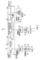
FIG. 2 is a simplified block diagram of one exemplary embodiment of a system consistent with the present invention; -
FIG. 3 is a simplified block diagram of a system consistent with the present invention including an exemplary controller consistent with the present invention; -
FIG. 4 is a timing diagram showing exemplary waveforms associated with an exemplary transmitter consistent with the invention; -
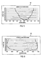
FIG. 5 shows plots of Q penalty vs. RZ error signal established by a controller consistent with the invention; -
FIG. 6 shows plots of Q penalty vs. NRZ error signal established by a controller consistent with the invention; -
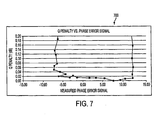
FIG. 7 shows plots of Q penalty vs. Phase error signal established by a controller consistent with the invention; and -
FIG. 8 is a block flow diagram illustrating an exemplary alarm bias and alignment control process performed by a controller consistent with the present invention. -
FIG. 1 is a simplified block diagram of one exemplary embodiment of aWDM transmission system 100 consistent with the present invention. The transmission system serves to transmit a plurality of optical channels over anoptical information path 102 from a transmittingterminal 104 to one or more remotely located receivingterminals 106. Those skilled in the art will recognize that thesystem 100 has been depicted as a highly simplified point-to-point system form for ease of explanation. For example, the transmittingterminal 104 and receivingterminal 106 may, of course, both be configured as transceivers, whereby each may be configured to perform both transmitting and receiving functions. For ease of explanation, however, the terminals are depicted and described herein with respect to only a transmitting or receiving function. It is to be understood that a system and method consistent with the invention may be incorporated into a wide variety of network components and configurations. The illustrated exemplary embodiments herein are provided only by way of explanation, not of limitation. - In the illustrated exemplary embodiment, each of a plurality of transmitters TX1, TX2 ... TXN receives a data signal on an associated input port 108-1, 108-2 ... 108-N, and transmits the data signal on associated wavelength λ1, λ2 ... λN. One or more of the transmitters TX1, TX2 ... TXN may be configured to modulate data on the associated wavelength with a RZ-DPSK modulation format while providing bias and/or alignment control in a manner consistent with the present invention. The transmitters, of course, are shown in highly simplified form for ease of explanation. Those skilled in the art will recognize that each transmitter may include electrical and optical components configured for transmitting the data signal at its associated wavelength with a desired amplitude and modulation.
- The transmitted wavelengths or channels are respectively carried on a plurality of paths 110-1, 110-2...110-N. The data channels are combined into an aggregate signal on
optical information channel 102 by a multiplexer orcombiner 112. Theoptical information channel 102 may include optical fiber waveguides, optical amplifiers, optical filters, dispersion compensating modules, and other active and passive components. - The aggregate signal may be received at one or more
remote receiving terminals 106. Ademultiplexer 114 separates the transmitted channels at wavelengths λ1, λ2... λN onto associated paths 116-1,116-2...116-N coupled to associated receivers RX1, RX2...RXN. One or more of the receivers RX1, RX2...RXN may be configured to demodulate a RZ-DPSK modulated signal and provide an associated output data signal on an associated output path 118-1, 118-2, 118-3, 118-N. - Turning to
FIG. 2 , there is illustrated anexemplary transmitter 200 consistent with the present invention. The illustrated exemplary embodiment includes a dual-stageoptical modulator 202, e.g. an LN modulator, including an RZ Mach-Zehnder type modulator 204 for imparting a periodic RZ intensity modulation and a NRZ Mach-Zehnder type modulator 206 for imparting an NRZ (DPSK) modulation to the intensity modulated signal. The two-stage modulator 202 may be driven in a known manner to modulate data onto a continuous waveoptical signal 208, e.g. from a laser source, with a RZ-DPSK modulation format. - For example, the
RZ modulator 204 may be driven in a well-known manner by the data clock to impart a periodic intensity modulation to the CWoptical signal 208. As shown, the data clock may be provided to a knowndivider 218 which provides an output including a train of identical sinusoidal pulses at half the data clock frequency. In one exemplary embodiment, the divider may receive a 12 GHz data clock signal and output a 6GHz drive signal. - The output of the
divider 218 may be provided to a known electrical phase shifter/delay circuit 220. Thephase shifter 220 may be configured to impart a timing delay to the output of thedivider 218 for purposes of adjusting the alignment of the RZ modulation to the NRZ (DPSK) data modulation. Optimal performance is achieved when the peak amplitude point of the RZ modulation is aligned with the center of the data bits modulated on the signal by the NRZ (DPSK)modulator 206. The timing delay imparted by the phase shifter may be controlled by aPhase bias 222 input to thephase shifter 220. - The output of the
phase shifter 220 may be coupled to anRF driver 224 for driving theRZ modulator 204. The nonlinear switching characteristic of the RZ modulator 204 doubles the frequency of the electrical drive signal from theRF driver 224, as is well known in the art, to impart the periodic intensity modulation to the optical signal at a frequency equal to the data rate. The intensity modulatedsignal 228 is provided at an output of theRZ modulator 204. Apower control mechanism 226 may be coupled to theRF driver 224. The power control mechanism may be configured to adjust the intensity modulation depth imparted tooptical information signal 208. The depth of modulation imparted by theRZ modulator 204 may be controlled by an amplitude control signal provided to thepower control mechanism 226. In an RZ-DPSK format the modulation depth may be set to 100%. Periodic intensity modulation may, however, be imparted to the CWoptical signal 208 at other modulation depths, as described, for example inU.S. Patent No. 6,556,326 (the '326 patent) to Neal S. Bergano, the teachings of which are incorporated herein by reference. - The NRZ modulator 206 may be driven to impart a DPSK modulation to the intensity modulated
optical signal 228 in a well-known manner. As shown, for example, a data stream and clock may be coupled to a known DPSK encoder 230. The output of the DPSK encoder 230 may be provided to anRF driver 232. TheRF driver 232 may drive theNRZ modulator 206 in response to the DPSK encoder 230 output to modulate the phase of the intensity modulatedoptical signal 228 in accordance with a DPSK modulation format, i.e. with ones and zeros indicated by differential phase transitions in the optical signal. Theoutput 244 of theNRZ modulator 206 is provided as themodulator 202 output and is a RZ-DPSK formatted optical signal. The modulation amplitude and the phase transition crossing point associated with the NRZ modulator may be adjusted using amplitude and crossing inputs to theRF driver 232. - Those of ordinary skill in the art will recognize that stable and accurate setting of the Mach-Zehnder modulator DC bias points and of the alignment of the RZ modulation to the data modulation are necessary to achieve a RZ-DPSK modulated signal that results in optimal system BER. In the illustrated exemplary embodiment, the modulator bias points and the alignment of the RZ modulation to the data modulation are established and controlled by a bias and
phase controller 234. Thecontroller 234 provides anRZ Bias output 236 to establish the DC bias of theRZ modulator 204, anNRZ Bias output 238 to establish the DC bias of theNRZ modulator 206, and aPhase Bias output 240 to thePhase Bias input 222 of the phase shifter to establish timing alignment between theRZ 204 andNRZ 206 modulators. - As is known, optical power from the two arms of a Mach-Zehnder modulator is coupled to the output of the modulator Y-branch as the modulator output. Optical power from the two arms is also scattered/radiated at or near the Y-branch coupler and does not appear at the modulator output. As used, herein "scattered light" and "light scattered" at the output of a modulator, or by a modulator, shall refer to the optical power from the two arms of a modulator that is scattered/radiated at or near the modulator Y-branch coupler.
- In general, the controller bias outputs are established by the
controller 234 in response to changes of the average power in the scattered light at the output of theNRZ modulator 206 when dithering the modulator bias settings. Thecontroller 234 amplifies, low pass filters and samples the current generated by aphotodetector 242, e.g. a photodiode, and mixes these samples separately with each dither signal to obtain an error value representing the energy in the photodetector current at each of the dither frequencies. The presence of energy at a particular dither frequency indicates that its associated bias voltage is not optimum. The error values are used to establish new associated bias settings. Optimum bias settings may be achieved by minimizing the associated error values. - In the illustrated exemplary embodiment, the average power in the light scattered by the
NRZ modulator 206 is derived from the output of thephotodetector 242, which is positioned in close proximity to the modulator Y-branch for detection of at least a portion of the light scattered at the output of the NRZ modulator. In one embodiment, thephotodetector 242 may be integrated into the dual-stage modulator package It has been recognized that use of a photodetector which monitors the light transmitted by the modulator, as opposed to the scattered light, can cause the RZ bias control loop to fail at a specific RZ modulation depths. Using a scattered light photo-detector 242 reduces or eliminates this problem since a much different pulse shape is imparted to the detector. -
FIG. 3 illustrates an exemplary embodiment of a bias and phase (modulation alignment)controller 234a consistent with the invention coupled to adual stage modulator 202. In operation, thecontroller 234a establishes initial bias settings, Phase Bias Setting, RZ Bias Setting, and NRZ Bias Setting, and applies low frequency dither signals Phase Dither, RZ Dither, NRZ Dither, respectively, to the settings. The Phase Bias Setting is added to the Phase Dither signal and provided to the phase shifter as thePhase Bias output 240 of the controller for aligning the relative phase of the RZ modulator 204 to theNRZ modulator 206. The RZ Bias Setting is added to the RZ Dither signal and provided to theRZ modulator 204 as theRZ Bias output 236 of the controller for setting the RZ modulator bias point, and the NRZ Bias Setting is added to the NRZ Dither signal and is provided as aNRZ output 238 of the controller to theNRZ modulator 206 for setting the NRZ modulator bias point. Thecontroller 234a adjusts the bias settings, Phase Bias Setting, RZ Bias Setting, and a NRZ Bias Setting, in response to associated error values derived from comparing the average power in the light scattered by theNRZ modulator 206 with the dither signals. - The illustrated
exemplary controller 234a generally includes anamplifier 300, a low pass filter (LPF) 302 andamplifier 304 coupled to the output of theamplifier 300, a digital signal processor (DSP) 306 including an analog-to-digital converter (ADC) 308, and a digital-to-analog converter (DAC) 310. As shown, thecurrent output 312 of thescattered photodetector 242 may be coupled to theamplifier 300. A variety of amplifier configurations are known to those of ordinary skill in the art. In one embodiment, theamplifier 300 may be configured as a logarithmic trans-impedance amplifier. A logarithmic trans-impedance amplifier allows the ADC and associated circuitry to operate correctly over a wide dynamic range of monitored photocurrents. - The output of the
amplifier 300 may be provided to the low pass filter (LPF) 302 andamplifier 304 configured to output an analog signal PAC containing dither signals recovered by thephotodetector 242, plus their harmonics and noise. In an embodiment wherein theamplifier 300 is configured as a linear amplifier, the output of theamplifier 300 may be provided to a secondlow pass filter 314 andamplifier 316 configured to provide an analog signal PDC, representative of the DC content of the monitored photocurrent. The PDC signal may be digitized by theADC 308, and sampled by theDSP 306, e.g. only once for each iteration of the control loop, to achieve a value representative of the average power. The average power value derived from PDC may be used to normalize the error values to ensure that the error values increase only when the associated bias setting moves in the wrong direction. - The digitized PAC signal is sampled by the
DSP 306. To simplify processing, the sampling may be conducted synchronously with the generation of the three dither signals Phase Dither, RZ Dither, NRZ dither. The PAC samples are mixed (i.e. multiplied) with each of the three generated dither tones Phase Dither, RZ Dither, NRZ dither. The result of each mixing is a signed error value which represents an error associated with each bias setting, e.g. mixing of Phase Dither with the samples produces an error value representing error in the Phase Bias Setting, mixing of RZ Dither with the samples produces an error value representing error in the RZ Bias Setting, and mixing of NRZ Dither produces an error value representing error in the NRZ Bias Setting. - Each of the signed error values may be coupled to a separate associated proportional-integral-differential controller (PID): Each PID may calculate new values for an associated one of the bias settings. The PID controllers may be implemented in the
DSP 306, e.g. in software, hardware or a combination thereof. TheDSP 306 may provide the new control setting values via a DAC interface 318 to theDAC 310, e.g. an SPI bus, which produces the new bias settings. The new bias settings, Phase Bias Setting, RZ Bias Setting, and NRZ Bias Setting provided by theDAC 310 may be added to their associated dither signals, Phase Dither, RZ Dither, NRZ dither, respectively, e.g. byadders -
FIG. 4 is a timing diagram showing exemplary PAC, RZ Dither, NRZ Dither, Phase Dither and sampling instants associated with an exemplary bias and phase controller consistent with the present invention. In a controller consistent with the present invention, the dither signals may be low frequency signals. As used herein, the term "low frequency" refers to a frequency that is at least an order of magnitude (i.e. a factor of 10) less than the modulator data rate. The term "low speed", as used herein, refers to a device having an operating bandwidth that is at least an order of magnitude (i.e. a factor of 10) less than the modulator data rate. Use of low frequency dither signals, allows use low frequency/low speed components, e.g. the scatteredlight photodetector 242,amplifier 300,LPF 302,ADC 308,DSP 306,DAC 310, etc. capable of manipulating and/or processing the dither signals. This reduces the cost and complexity of the system compared to high frequency (bandwidth on the order of the data rate) designs. - The PAC signal 400 shown in
FIG. 4 is an analog signal. PAC is digitized by theADC 308 and sampled N times by theDSP 306 for each iteration of the control loop. In one embodiment, a 60 KHz sampling frequency may be used to provide 60 samples (N=60) for each iteration of the control loop. The PAC samples are multiplied, separately, by theRZ Dither 402 ,NRZ dither 404 andPhase Dither 406 signals to obtain separate error values associated with the RZ bias, NRZ bias, and Phase bias, respectively. - To avoid interference between the RZ Bias, NRZ Bias and Phase Bias control loops, each dither signal may have a different frequency. In an embodiment including a 60 kHz sampling frequency, the RZ dither frequency may be about 5 kHz, the NRZ dither frequency may be about 3 kHz, and the Phase dither frequency may be about 2 kHz. Those of ordinary skill in the art will recognize that a variety of other sampling and dither frequencies may be provided. To avoid interference between the dither frequencies, however, the dither frequencies may be established such the no dither frequency is an integer multiple of any other dither frequency, and the period, TRZ, TNRZ, TPhase, respectively, of the dither signals are a factor ofN.
- In addition, to simplify the controller the phase of the dither signals may be optimized with respect to the digitized PAC signal. The controller may be configured, e.g. through software, hardware or a combination of software and hardware, to allow for deterministic low frequency phase differences between the dither signals and the digitized PAC signal. The optimal phase value for each dither signal may be determined by purposefully misadjusting the bias signals and measuring the error values as a function of the phase value. The phase value may be set for each loop at a value that minimizes the error value.
- Consistent with the present invention, the optimal setting for the RZ bias, NRZ bias and Phase bias signals may be achieved by minimizing the associated signed error values.
FIGS 5-7 , for example, illustrate the Q penalty vs. error signal value associated with one exemplary controller consistent with the invention wherein the RZ pulse width is characterized by a carrier-to-side-band ratio (CSR) of 7.5 dB. The illustrated Q penalty represents the decrease in Q associated with incorrect biasing compared to the Q achieved with optimal biasing, i.e. a Q penalty of 0 dB represents optimal biasing.FIG. 5 includes aplot 500 of Q penalty vs. the RZ error signal value established by the controller.FIG. 6 includes a plot 600 of Q penalty vs. the NRZ error signal value established by the controller.FIG. 7 includes aplot 700 of Q penalty vs. the Phase error signal value established by the controller. As shown, for a CSR of 7.5 dB the Q penalty associated with the modulator bias settings is below about 0.02 dB when the error signals values are minimized, e.g. approximately zero. - Those of ordinary skill in the art will recognize numerous methods of minimizing the error signal values to achieve optimum bias settings. In one embodiment, for example, the error signal values may be minimized by perturbing the bias settings to achieve a minimum error. A new bias setting may be calculated and written to the DAC in response to each signed error value. The sign (+/-) of the error value may establish a direction of change in the associated bias signal. The bias may be changed in any increment. Smaller incremental changes in the bias lead to increased bias resolution and accuracy. In one embodiment, the bias may be changed by a constant multiple of the error value. The optimum bias may be achieved when the same change in the associated average power is achieved when the bias is changed in one direction and then back to the optimum as is achieved when the bias is changed in the opposite direction and then back to the optimum. When the optimum bias is achieved the average power no longer contains a spectral component at the fundamental of the associated dither frequency. The average power may still contain spectral components at harmonics of the dither frequency.
-
FIG. 8 is a block flow diagram of one example of a bias andalignment control process 800 performed by a controller consistent with the present invention. The block flow diagram is illustrated with a particular sequences of steps. It can be appreciated, however, that the sequence of steps merely provides an example of how the general functionality described herein can be implemented. Further, each sequence of steps does not have to be executed in the order presented unless otherwise indicated. - In the exemplary embodiment illustrated in
FIG. 8 , the process starts 802 with initializing 804 each bias control loop. The initialization may include setting the RZ Bias Setting, NRZ Bias Setting and Phase Bias Setting values to levels located at the middle of the bias ranges, and activating the RZ Dither, NRZ Dither, and Phase Dither signals. The RZ Bias Setting, NRZ Bias Setting and Phase Bias Setting may be written to theDAC 806. Adelay 808 may be provided to allow the bias settings to settle into the DAC analog circuitry and appear at the DAC output for addition to the dither signals. - Once the initial bias signals and dither signals are added and provided at the associated ports of the RZ modulator, NRZ modulator and phase shifter, N samples of the PAC signal may be taken 810 by the DSP. The samples may be mixed with the dither signals to establish the error values 812, and bias adjustments may be calculated 814 from the error values. If the adjusted bias signals are within a predetermined expected
range 816, they may be written to theDACS 806 and flow may continue. Otherwise, a bias control alarm may be set 818 and flow may return to theinitialization step 804. - There is thus provided a method and apparatus for bias and alignment control in a RZ-DPSK transmitter that provides stable, accurate, and efficient bias and alignment control. In one exemplary embodiment, the apparatus includes a dual-stage Mach-Zehnder modulator for modulating data on an optical signal with a modulation format having a periodic intensity modulation and a DPSK data modulation. The modulator may include a Mach-Zehnder RZ modulator for imparting the periodic intensity modulation in response to a RZ bias signal, and a Mach-Zehnder NRZ modulator for imparting the DPSK data modulation in response to a NRZ bias signal. A phase shifter may be provided for selectively aligning the periodic intensity modulation and the data modulation in response to a phase bias signal. A low speed photodetector may be configured to detect scattered light at the output of the modulator. The low speed photo-detector may have a bandwidth of at least one order of magnitude less than a data rate of the data and be configured to provide an output representative of power scattered by the NRZ modulator. A controller may provide at least one of the RZ bias signal, the NRZ bias signal, or the phase bias signal, in response to the output of the low speed photodetector.
- The embodiments that have been described herein but some of the several which utilize this invention and are set forth here by way of illustration but not of limitation. Many other embodiments, which will be readily apparent to those skilled in the art, may be made without departing materially from the spirit and scope of the invention.
Claims (24)
- An apparatus (200) for transmitting an optical signal, said apparatus comprising:a modulator (202) for modulating data on an optical signal (208) with a modulation format having a periodic intensity modulation and a differential phase shift keying (DPSK) data modulation, said modulator (202) comprising a Mach-Zehnder RZ modulator (204) for imparting said periodic intensity modulation in response to a RZ bias signal (236), and a Mach-Zehnder NRZ modulator (206) for imparting said DPSK data modulation in response to a NRZ bias signal (238);a phase shifter (220) for selectively aligning said periodic intensity modulation and said data modulation in response to a phase bias signal (222); andcharacterized in that the apparatus further comprises:a low speed photo-detector (242), said low speed photo-detector having a bandwidth of at least one order of magnitude less than a data rate of said data and being configured to detect light scattered at an output of said NRZ modulator and provide an output representative of power in said light scattered at said output of said NRZ modulator; anda controller (234) for providing at least one of said RZ bias signal, said NRZ bias signal, or said phase bias signal, in response to said output of said low speed photodetector.
- An apparatus according to claim 1, wherein said controller (234) is configured for providing each of said RZ bias signal (236), said NRZ bias signal (238), and said phase bias signal (240) in response to said output of said low speed photodetector.
- An apparatus according to claim 1 or 2, wherein an input of said Mach-Zehnder NRZ modulator (206) is coupled to an output of said Mach-Zehnder RZ modulator (204), and wherein an output (244) of said Mach-Zehnder NRZ modulator is provided as said output of said modulator.
- An apparatus according to any preceding claim, wherein said phase shifter (220) is coupled to said Mach-Zehnder RZ modulator (204) for selectively aligning said periodic intensity modulation with said data modulation.
- An apparatus according to any preceding claim, wherein said controller (234) is configured for providing said phase bias signal (240) in response to said output of said low speed photodetector (242), and wherein said phase bias signal comprises a low frequency phase bias dither (406), said low frequency phase bias dither having a frequency at least one order of magnitude less than said data rate.
- An apparatus according to claim 5, wherein said controller (234) provides said phase bias signal in response to a phase bias error value obtained by mixing a signal representative of said output of said photodetector (242) with a signal representative of said phase bias dither.
- An apparatus according to claim 6, wherein said controller (234) is configured to adjust said phase bias signal (240) to minimize said phase bias error value.
- An apparatus according to any preceding claim, wherein said controller (234) is configured for providing said RZ bias signal (236) in response to said output of said low speed photodetector (242), and wherein said RZ bias signal comprises a low frequency RZ bias dither (402), said low frequency RZ bias dither having a frequency at least one order of magnitude less than said data rate.
- An apparatus according to claim 8, wherein said controller (234) provides said RZ bias signal in response to a RZ bias error value obtained by mixing a signal representative of said output of said photodetector with a signal representative of said RZ bias dither,
- An apparatus according to claim 9, wherein said controller (234) is configured to adjust said RZ bias signal to minimize said RZ bias error value.
- An apparatus according to any preceding claim, wherein said controller (234) is configured for providing said NRZ bias signal (238) in response to said output of said low speed photodetector, and wherein said NRZ bias signal comprises a low frequency NRZ bias dither (404), said low frequency NRZ bias dither having a frequency at least one order of magnitude less than said data rate.
- An apparatus according to claim 11, wherein said controller (234) provides said NRZ bias signal (338) in response to a NRZ bias error value obtained by mixing a signal representative of said output of said photodetector with a signal representative of said NRZ bias dither (404).
- An apparatus according to claim 12, wherein said controller (234) is configured to adjust said NRZ bias signal (238) to minimize said NRZ bias error value.
- A method (800) of operating a modulator (202) for modulating data on an optical signal (208) with a modulation format having a periodic intensity modulation and a differential phase shift keying (DPSK) data modulation, said modulator (202) comprising a Mach-Zehnder RZ modulator (204) for imparting said periodic intensity modulation in response to a RZ bias signal (236), and a Mach-Zehnder NRZ modulator (206) for imparting said DPSK data modulation in response to a NRZ bias signal (238), and having a phase shifter (220) coupled thereto for selectively aligning said periodic intensity modulation and said data modulation in response to a phase bias signal (222), said method characterized by:detecting (810) power in light scattered at an output of said NRZ modulator (206) using a low speed photo-detector (242), said low speed photo-detector having a bandwidth of at least one order of magnitude less than a data rate of said data and being configured to provide an output representative of said power of said scattered light at said output of said modulator; andproviding (814) at least one of said phase bias signal, said RZ bias signal, or said NRZ bias signal in response to said output of said low speed photodetector.
- A method according to claim 14, said method comprising providing each of said RZ bias signal (236), said NRZ bias signal (238), and said phase bias signal (240) in response to said output of said low speed photodetector (242).
- A method according to claim 14 or 15, said method comprising providing said phase bias signal (240) in response to said output of said low speed photodetector (242), and wherein said phase bias signal comprises a low frequency phase bias dither (406), said low frequency phase bias dither having a frequency at least one order of magnitude less than said data rate.
- A method according to claim 16, said method comprising providing said phase bias signal (240) in response to a phase bias error value obtained by mixing a signal representative of said output of said photodetector (242) with a signal representative of said phase bias dither (406).
- A method according to claim 17, said method further comprising adjusting said phase bias signal (240) to minimize said phase bias error value.
- A method according to any of claims 14 to 18, said method comprising providing said RZ bias signal (236) in response to said output of said low speed photodetector (242), and wherein said RZ bias signal (236) comprises a low frequency RZ bias dither (402), said low frequency RZ bias dither having a frequency at least one order of magnitude less than said data rate.
- A method according to claim 19, said method comprising providing said RZ bias signal (236) in response to a RZ bias error value obtained by mixing a signal representative of said output of said photodetector (242) with a signal representative of said RZ bias dither (402).
- A method according to claim 20, said method further comprising adjusting said RZ bias signal (236) to minimize said RZ bias error value.
- A method according to any of claims 14 to 21, said method comprising providing said NRZ bias signal (238) in response to said output of said low speed photodetector (242), and wherein said bias signal comprises a low frequency NRZ bias dither (404), said low frequency NRZ bias dither having a frequency at least one order of magnitude less than said data rate.
- A method according to claim 22, said method comprising providing said NRZ bias signal (238) in response to a NRZ bias error value obtained by mixing a signal representative of said output of said photodetector with a signal representative of said NRZ bias dither (404).
- A method according to claim 23, said method further comprising adjusting said NRZ bias signal (238) to minimize said NRZ bias error value.
Applications Claiming Priority (2)
| Application Number | Priority Date | Filing Date | Title |
|---|---|---|---|
| US11/012,369 US7398023B2 (en) | 2004-12-15 | 2004-12-15 | Method and apparatus for bias and alignment control in an optical signal transmitter |
| PCT/US2005/045215 WO2006065887A2 (en) | 2004-12-15 | 2005-12-14 | Method and apparatus for bias and alignment control in an optical signal transmitter |
Publications (3)
| Publication Number | Publication Date |
|---|---|
| EP1825612A2 EP1825612A2 (en) | 2007-08-29 |
| EP1825612A4 EP1825612A4 (en) | 2010-02-17 |
| EP1825612B1 true EP1825612B1 (en) | 2013-06-26 |
Family
ID=36584027
Family Applications (1)
| Application Number | Title | Priority Date | Filing Date |
|---|---|---|---|
| EP05854014.7A Expired - Lifetime EP1825612B1 (en) | 2004-12-15 | 2005-12-14 | Method and apparatus for bias and alignment control in an optical signal transmitter |
Country Status (8)
| Country | Link |
|---|---|
| US (1) | US7398023B2 (en) |
| EP (1) | EP1825612B1 (en) |
| JP (1) | JP5253813B2 (en) |
| KR (1) | KR101185098B1 (en) |
| CN (1) | CN101084634B (en) |
| AU (1) | AU2005317102B2 (en) |
| CA (1) | CA2588585C (en) |
| WO (1) | WO2006065887A2 (en) |
Families Citing this family (30)
| Publication number | Priority date | Publication date | Assignee | Title |
|---|---|---|---|---|
| JP4149298B2 (en) * | 2003-03-27 | 2008-09-10 | 富士通株式会社 | Control device for optical modulator |
| US8532499B2 (en) * | 2005-10-25 | 2013-09-10 | Emcore Corporation | Optical transmitter with adaptively controlled optically linearized modulator |
| US7853155B2 (en) * | 2005-12-12 | 2010-12-14 | Emcore Corporation | Method for adjusting bias in optical transmitter with external modulator |
| US7463802B2 (en) * | 2006-01-13 | 2008-12-09 | Emcore Corporation | Integrated circuit for adjusting bias in optical transmitter with external modulator |
| JP4910476B2 (en) * | 2006-05-22 | 2012-04-04 | 富士通株式会社 | Optical communication device |
| JP2008129476A (en) * | 2006-11-24 | 2008-06-05 | Yokogawa Electric Corp | Light modulator |
| JP2008211439A (en) * | 2007-02-26 | 2008-09-11 | Yokogawa Electric Corp | Optical transmitter |
| JP4983466B2 (en) * | 2007-07-30 | 2012-07-25 | 富士通株式会社 | Optical modulation device, optical modulation method, and optical transmission device |
| JP5476697B2 (en) * | 2008-09-26 | 2014-04-23 | 富士通株式会社 | Optical signal transmitter |
| US8175465B2 (en) * | 2008-11-12 | 2012-05-08 | Lockheed Martin Corporation | Bias control apparatus and method for optical modulator |
| JP5353428B2 (en) * | 2009-05-12 | 2013-11-27 | 住友大阪セメント株式会社 | Light modulator |
| CN101895357B (en) * | 2010-07-12 | 2012-05-30 | 上海新干通通信设备有限公司 | Multi-frequency FM broadcasting system capable of switching in emergency alarm voice signal |
| JP5760419B2 (en) * | 2010-12-13 | 2015-08-12 | 富士通株式会社 | Optical transmission device and optical transmission method |
| KR20120099171A (en) * | 2011-02-10 | 2012-09-07 | 한국전자통신연구원 | Apparatus and method for controlling optical signal, and device for generating optical signal with the said apparatus |
| CN102156499B (en) * | 2011-04-06 | 2013-06-19 | 烽火通信科技股份有限公司 | Method and device for bias control for optical phase delayer based on logarithm detection |
| US8606114B2 (en) * | 2011-05-17 | 2013-12-10 | Oclaro Technology Limited | Alignment of a data signal to an alignment signal |
| US9158137B1 (en) * | 2011-09-02 | 2015-10-13 | Eospace Inc. | Spread-spectrum bias control |
| EP2896988B1 (en) * | 2012-09-12 | 2018-08-08 | Mitsubishi Electric Corporation | Optical transmitter and dc bias control method |
| US9467227B2 (en) * | 2014-03-13 | 2016-10-11 | Luxtera, Inc. | Method and system for an optical connection service interface |
| CN105871533A (en) * | 2015-01-20 | 2016-08-17 | 中兴通讯股份有限公司 | Phase processing method and device |
| JP6572659B2 (en) * | 2015-07-28 | 2019-09-11 | 富士通オプティカルコンポーネンツ株式会社 | Optical transmitter and control method |
| EP3358397B1 (en) * | 2015-09-28 | 2021-02-17 | Nec Corporation | Optical modulator, optical transmitter, and optical modulation method |
| JP2017103646A (en) * | 2015-12-02 | 2017-06-08 | 日本電信電話株式会社 | Optical transmitter |
| WO2017123243A1 (en) * | 2016-01-15 | 2017-07-20 | Hewlett Packard Enterprise Development Lp | Optical signal modulation |
| US20180176665A1 (en) * | 2016-12-15 | 2018-06-21 | National Sun Yat-Sen University | Method and apparatus for signal processing by light waveform shaping |
| WO2019187335A1 (en) * | 2018-03-30 | 2019-10-03 | 日本電気株式会社 | Light transmission/reception device, light modulator control method, and non-temporary computer readable medium storing light modulator control program |
| US11509275B2 (en) * | 2018-04-20 | 2022-11-22 | Neophotonics Corporation | Method and apparatus for bias control with a large dynamic range for Mach-Zehnder modulators |
| CN108768523A (en) * | 2018-05-30 | 2018-11-06 | 大连理工大学 | A kind of underwater general optical communication system |
| JP7793181B2 (en) * | 2021-12-17 | 2026-01-05 | シンクランド株式会社 | Optical System |
| CN115882963B (en) * | 2022-12-09 | 2024-07-02 | 华中科技大学 | Hidden communication device and system |
Family Cites Families (14)
| Publication number | Priority date | Publication date | Assignee | Title |
|---|---|---|---|---|
| JP3723358B2 (en) * | 1998-11-25 | 2005-12-07 | 富士通株式会社 | Optical modulation device and optical modulator control method |
| JP3591346B2 (en) * | 1998-12-08 | 2004-11-17 | 富士通株式会社 | Light modulator |
| DE60142814D1 (en) * | 2000-02-28 | 2010-09-30 | Nippon Telegraph & Telephone | Optical transmission method, optical transmitter and optical receiver |
| JP2001296506A (en) * | 2000-04-13 | 2001-10-26 | Nec Corp | RZ optical transmitter |
| US6952534B1 (en) | 2000-08-25 | 2005-10-04 | Alcatel | System and method for generating return-to-zero (RZ) optical data in a digital lightwave communications system |
| US20020114047A1 (en) * | 2000-11-22 | 2002-08-22 | Jds Uniphase Corporation | Cascaded RZ and NRZ laser modulators having RZ/NRZ phase alignment bias control |
| US20030007216A1 (en) * | 2001-06-21 | 2003-01-09 | Chraplyvy Andrew Roman | Long haul transmission in a dispersion managed optical communication system |
| US6671079B2 (en) * | 2001-12-14 | 2003-12-30 | Lucent Technologies Inc. | Method and apparatus for transmitting a modulated optical signal |
| JP3974792B2 (en) * | 2002-02-07 | 2007-09-12 | 富士通株式会社 | Optical waveguide device and optical device |
| US7394992B2 (en) * | 2002-03-15 | 2008-07-01 | Mintera Corporation | Control of an optical modulator for desired biasing of data and pulse modulators |
| JP3892326B2 (en) * | 2002-03-26 | 2007-03-14 | 富士通株式会社 | Control device for optical modulator |
| JP3863896B2 (en) * | 2002-12-16 | 2006-12-27 | 富士通株式会社 | Optical modulator driving circuit and driving method |
| JP4069036B2 (en) * | 2003-08-15 | 2008-03-26 | 日本電信電話株式会社 | Mark rate evaluation system |
| US6972842B2 (en) | 2003-08-25 | 2005-12-06 | Lucent Technologies Inc. | Monitoring alignment between pulse carvers and phase modulators in optical systems |
-
2004
- 2004-12-15 US US11/012,369 patent/US7398023B2/en not_active Expired - Lifetime
-
2005
- 2005-12-14 AU AU2005317102A patent/AU2005317102B2/en not_active Ceased
- 2005-12-14 WO PCT/US2005/045215 patent/WO2006065887A2/en not_active Ceased
- 2005-12-14 CA CA2588585A patent/CA2588585C/en not_active Expired - Fee Related
- 2005-12-14 EP EP05854014.7A patent/EP1825612B1/en not_active Expired - Lifetime
- 2005-12-14 CN CN200580043288XA patent/CN101084634B/en not_active Expired - Fee Related
- 2005-12-14 JP JP2007546851A patent/JP5253813B2/en not_active Expired - Fee Related
- 2005-12-14 KR KR1020077013391A patent/KR101185098B1/en not_active Expired - Fee Related
Also Published As
| Publication number | Publication date |
|---|---|
| WO2006065887A2 (en) | 2006-06-22 |
| AU2005317102B2 (en) | 2010-03-18 |
| JP2008524655A (en) | 2008-07-10 |
| US20060127103A1 (en) | 2006-06-15 |
| WO2006065887A3 (en) | 2006-11-16 |
| KR101185098B1 (en) | 2012-09-21 |
| CN101084634B (en) | 2011-08-10 |
| CA2588585C (en) | 2015-02-03 |
| AU2005317102A1 (en) | 2006-06-22 |
| EP1825612A2 (en) | 2007-08-29 |
| EP1825612A4 (en) | 2010-02-17 |
| US7398023B2 (en) | 2008-07-08 |
| CA2588585A1 (en) | 2006-06-22 |
| JP5253813B2 (en) | 2013-07-31 |
| CN101084634A (en) | 2007-12-05 |
| KR20070104524A (en) | 2007-10-26 |
Similar Documents
| Publication | Publication Date | Title |
|---|---|---|
| CA2588585C (en) | Method and apparatus for bias and alignment control in an optical signal transmitter | |
| US9419720B2 (en) | Optical signal transmitter | |
| US8412047B2 (en) | Polarization multiplexed light transmitter and control method thereof | |
| US6970655B2 (en) | Method and circuit for generating single-sideband optical signal | |
| US7978390B2 (en) | Optical modulator | |
| US6809849B2 (en) | Control apparatus and control method for an optical method | |
| US9692519B2 (en) | Level spacing for M-PAM optical systems with coherent detection | |
| EP1906564A1 (en) | Optical transmitter | |
| EP1919105B1 (en) | Optical transmitter and optical transmission system | |
| JP5811531B2 (en) | Optical transmitter, optical communication system, and optical transmission method | |
| US7330666B1 (en) | Method and apparatus for controlling modulator phase alignment in a transmitter of an optical communications system | |
| EP3497825B1 (en) | Encoding for optical transmission | |
| US7155071B2 (en) | Device for Mach-Zehnder modulator bias control for duobinary optical transmission and associated system and method | |
| US8811827B2 (en) | System for generating optical RZ signals based on electrical RZ signals | |
| EP1873575B1 (en) | Optical modulation apparatus and method to control it |
Legal Events
| Date | Code | Title | Description |
|---|---|---|---|
| PUAI | Public reference made under article 153(3) epc to a published international application that has entered the european phase |
Free format text: ORIGINAL CODE: 0009012 |
|
| 17P | Request for examination filed |
Effective date: 20070614 |
|
| AK | Designated contracting states |
Kind code of ref document: A2 Designated state(s): AT BE BG CH CY CZ DE DK EE ES FI FR GB GR HU IE IS IT LI LT LU LV MC NL PL PT RO SE SI SK TR |
|
| DAX | Request for extension of the european patent (deleted) | ||
| RAP1 | Party data changed (applicant data changed or rights of an application transferred) |
Owner name: TYCO TELECOMMUNICATIONS (US) INC. |
|
| A4 | Supplementary search report drawn up and despatched |
Effective date: 20100115 |
|
| RIC1 | Information provided on ipc code assigned before grant |
Ipc: H04B 10/155 20060101AFI20100111BHEP |
|
| RAP1 | Party data changed (applicant data changed or rights of an application transferred) |
Owner name: TYCO ELECTRONICS SUBSEA COMMUNICATIONS LLC |
|
| 17Q | First examination report despatched |
Effective date: 20100316 |
|
| RAP1 | Party data changed (applicant data changed or rights of an application transferred) |
Owner name: TYCO ELECTRONICS SUBSEA COMMUNICATIONS LLC |
|
| REG | Reference to a national code |
Ref country code: DE Ref legal event code: R079 Ref document number: 602005040194 Country of ref document: DE Free format text: PREVIOUS MAIN CLASS: H04B0010040000 Ipc: H04B0010500000 |
|
| RIC1 | Information provided on ipc code assigned before grant |
Ipc: H04B 10/50 20130101AFI20130129BHEP |
|
| GRAP | Despatch of communication of intention to grant a patent |
Free format text: ORIGINAL CODE: EPIDOSNIGR1 |
|
| GRAS | Grant fee paid |
Free format text: ORIGINAL CODE: EPIDOSNIGR3 |
|
| GRAA | (expected) grant |
Free format text: ORIGINAL CODE: 0009210 |
|
| AK | Designated contracting states |
Kind code of ref document: B1 Designated state(s): AT BE BG CH CY CZ DE DK EE ES FI FR GB GR HU IE IS IT LI LT LU LV MC NL PL PT RO SE SI SK TR |
|
| REG | Reference to a national code |
Ref country code: GB Ref legal event code: FG4D |
|
| REG | Reference to a national code |
Ref country code: CH Ref legal event code: EP |
|
| REG | Reference to a national code |
Ref country code: AT Ref legal event code: REF Ref document number: 619083 Country of ref document: AT Kind code of ref document: T Effective date: 20130715 |
|
| REG | Reference to a national code |
Ref country code: IE Ref legal event code: FG4D |
|
| REG | Reference to a national code |
Ref country code: DE Ref legal event code: R096 Ref document number: 602005040194 Country of ref document: DE Effective date: 20130822 |
|
| PG25 | Lapsed in a contracting state [announced via postgrant information from national office to epo] |
Ref country code: SE Free format text: LAPSE BECAUSE OF FAILURE TO SUBMIT A TRANSLATION OF THE DESCRIPTION OR TO PAY THE FEE WITHIN THE PRESCRIBED TIME-LIMIT Effective date: 20130626 Ref country code: SI Free format text: LAPSE BECAUSE OF FAILURE TO SUBMIT A TRANSLATION OF THE DESCRIPTION OR TO PAY THE FEE WITHIN THE PRESCRIBED TIME-LIMIT Effective date: 20130626 Ref country code: GR Free format text: LAPSE BECAUSE OF FAILURE TO SUBMIT A TRANSLATION OF THE DESCRIPTION OR TO PAY THE FEE WITHIN THE PRESCRIBED TIME-LIMIT Effective date: 20130927 Ref country code: LT Free format text: LAPSE BECAUSE OF FAILURE TO SUBMIT A TRANSLATION OF THE DESCRIPTION OR TO PAY THE FEE WITHIN THE PRESCRIBED TIME-LIMIT Effective date: 20130626 Ref country code: FI Free format text: LAPSE BECAUSE OF FAILURE TO SUBMIT A TRANSLATION OF THE DESCRIPTION OR TO PAY THE FEE WITHIN THE PRESCRIBED TIME-LIMIT Effective date: 20130626 |
|
| REG | Reference to a national code |
Ref country code: AT Ref legal event code: MK05 Ref document number: 619083 Country of ref document: AT Kind code of ref document: T Effective date: 20130626 |
|
| REG | Reference to a national code |
Ref country code: LT Ref legal event code: MG4D |
|
| PG25 | Lapsed in a contracting state [announced via postgrant information from national office to epo] |
Ref country code: BG Free format text: LAPSE BECAUSE OF FAILURE TO SUBMIT A TRANSLATION OF THE DESCRIPTION OR TO PAY THE FEE WITHIN THE PRESCRIBED TIME-LIMIT Effective date: 20130926 |
|
| REG | Reference to a national code |
Ref country code: NL Ref legal event code: VDEP Effective date: 20130626 |
|
| PG25 | Lapsed in a contracting state [announced via postgrant information from national office to epo] |
Ref country code: LV Free format text: LAPSE BECAUSE OF FAILURE TO SUBMIT A TRANSLATION OF THE DESCRIPTION OR TO PAY THE FEE WITHIN THE PRESCRIBED TIME-LIMIT Effective date: 20130626 |
|
| PG25 | Lapsed in a contracting state [announced via postgrant information from national office to epo] |
Ref country code: AT Free format text: LAPSE BECAUSE OF FAILURE TO SUBMIT A TRANSLATION OF THE DESCRIPTION OR TO PAY THE FEE WITHIN THE PRESCRIBED TIME-LIMIT Effective date: 20130626 Ref country code: CZ Free format text: LAPSE BECAUSE OF FAILURE TO SUBMIT A TRANSLATION OF THE DESCRIPTION OR TO PAY THE FEE WITHIN THE PRESCRIBED TIME-LIMIT Effective date: 20130626 Ref country code: EE Free format text: LAPSE BECAUSE OF FAILURE TO SUBMIT A TRANSLATION OF THE DESCRIPTION OR TO PAY THE FEE WITHIN THE PRESCRIBED TIME-LIMIT Effective date: 20130626 Ref country code: SK Free format text: LAPSE BECAUSE OF FAILURE TO SUBMIT A TRANSLATION OF THE DESCRIPTION OR TO PAY THE FEE WITHIN THE PRESCRIBED TIME-LIMIT Effective date: 20130626 Ref country code: IS Free format text: LAPSE BECAUSE OF FAILURE TO SUBMIT A TRANSLATION OF THE DESCRIPTION OR TO PAY THE FEE WITHIN THE PRESCRIBED TIME-LIMIT Effective date: 20131026 Ref country code: PT Free format text: LAPSE BECAUSE OF FAILURE TO SUBMIT A TRANSLATION OF THE DESCRIPTION OR TO PAY THE FEE WITHIN THE PRESCRIBED TIME-LIMIT Effective date: 20131028 Ref country code: BE Free format text: LAPSE BECAUSE OF FAILURE TO SUBMIT A TRANSLATION OF THE DESCRIPTION OR TO PAY THE FEE WITHIN THE PRESCRIBED TIME-LIMIT Effective date: 20130626 Ref country code: CY Free format text: LAPSE BECAUSE OF FAILURE TO SUBMIT A TRANSLATION OF THE DESCRIPTION OR TO PAY THE FEE WITHIN THE PRESCRIBED TIME-LIMIT Effective date: 20130724 |
|
| PG25 | Lapsed in a contracting state [announced via postgrant information from national office to epo] |
Ref country code: NL Free format text: LAPSE BECAUSE OF FAILURE TO SUBMIT A TRANSLATION OF THE DESCRIPTION OR TO PAY THE FEE WITHIN THE PRESCRIBED TIME-LIMIT Effective date: 20130626 Ref country code: RO Free format text: LAPSE BECAUSE OF FAILURE TO SUBMIT A TRANSLATION OF THE DESCRIPTION OR TO PAY THE FEE WITHIN THE PRESCRIBED TIME-LIMIT Effective date: 20130626 Ref country code: ES Free format text: LAPSE BECAUSE OF FAILURE TO SUBMIT A TRANSLATION OF THE DESCRIPTION OR TO PAY THE FEE WITHIN THE PRESCRIBED TIME-LIMIT Effective date: 20131007 Ref country code: PL Free format text: LAPSE BECAUSE OF FAILURE TO SUBMIT A TRANSLATION OF THE DESCRIPTION OR TO PAY THE FEE WITHIN THE PRESCRIBED TIME-LIMIT Effective date: 20130626 |
|
| PG25 | Lapsed in a contracting state [announced via postgrant information from national office to epo] |
Ref country code: CY Free format text: LAPSE BECAUSE OF FAILURE TO SUBMIT A TRANSLATION OF THE DESCRIPTION OR TO PAY THE FEE WITHIN THE PRESCRIBED TIME-LIMIT Effective date: 20130626 |
|
| PG25 | Lapsed in a contracting state [announced via postgrant information from national office to epo] |
Ref country code: DK Free format text: LAPSE BECAUSE OF FAILURE TO SUBMIT A TRANSLATION OF THE DESCRIPTION OR TO PAY THE FEE WITHIN THE PRESCRIBED TIME-LIMIT Effective date: 20130626 |
|
| PLBE | No opposition filed within time limit |
Free format text: ORIGINAL CODE: 0009261 |
|
| STAA | Information on the status of an ep patent application or granted ep patent |
Free format text: STATUS: NO OPPOSITION FILED WITHIN TIME LIMIT |
|
| PG25 | Lapsed in a contracting state [announced via postgrant information from national office to epo] |
Ref country code: IT Free format text: LAPSE BECAUSE OF FAILURE TO SUBMIT A TRANSLATION OF THE DESCRIPTION OR TO PAY THE FEE WITHIN THE PRESCRIBED TIME-LIMIT Effective date: 20130626 |
|
| 26N | No opposition filed |
Effective date: 20140327 |
|
| REG | Reference to a national code |
Ref country code: DE Ref legal event code: R097 Ref document number: 602005040194 Country of ref document: DE Effective date: 20140327 |
|
| REG | Reference to a national code |
Ref country code: CH Ref legal event code: PL |
|
| GBPC | Gb: european patent ceased through non-payment of renewal fee |
Effective date: 20131214 |
|
| PG25 | Lapsed in a contracting state [announced via postgrant information from national office to epo] |
Ref country code: MC Free format text: LAPSE BECAUSE OF FAILURE TO SUBMIT A TRANSLATION OF THE DESCRIPTION OR TO PAY THE FEE WITHIN THE PRESCRIBED TIME-LIMIT Effective date: 20130626 Ref country code: LU Free format text: LAPSE BECAUSE OF FAILURE TO SUBMIT A TRANSLATION OF THE DESCRIPTION OR TO PAY THE FEE WITHIN THE PRESCRIBED TIME-LIMIT Effective date: 20131214 |
|
| REG | Reference to a national code |
Ref country code: IE Ref legal event code: MM4A |
|
| PG25 | Lapsed in a contracting state [announced via postgrant information from national office to epo] |
Ref country code: LI Free format text: LAPSE BECAUSE OF NON-PAYMENT OF DUE FEES Effective date: 20131231 Ref country code: IE Free format text: LAPSE BECAUSE OF NON-PAYMENT OF DUE FEES Effective date: 20131214 Ref country code: CH Free format text: LAPSE BECAUSE OF NON-PAYMENT OF DUE FEES Effective date: 20131231 |
|
| PG25 | Lapsed in a contracting state [announced via postgrant information from national office to epo] |
Ref country code: GB Free format text: LAPSE BECAUSE OF NON-PAYMENT OF DUE FEES Effective date: 20131214 |
|
| PG25 | Lapsed in a contracting state [announced via postgrant information from national office to epo] |
Ref country code: TR Free format text: LAPSE BECAUSE OF FAILURE TO SUBMIT A TRANSLATION OF THE DESCRIPTION OR TO PAY THE FEE WITHIN THE PRESCRIBED TIME-LIMIT Effective date: 20130626 |
|
| PG25 | Lapsed in a contracting state [announced via postgrant information from national office to epo] |
Ref country code: HU Free format text: LAPSE BECAUSE OF FAILURE TO SUBMIT A TRANSLATION OF THE DESCRIPTION OR TO PAY THE FEE WITHIN THE PRESCRIBED TIME-LIMIT; INVALID AB INITIO Effective date: 20051214 |
|
| REG | Reference to a national code |
Ref country code: FR Ref legal event code: PLFP Year of fee payment: 11 |
|
| PGFP | Annual fee paid to national office [announced via postgrant information from national office to epo] |
Ref country code: FR Payment date: 20151217 Year of fee payment: 11 |
|
| PGFP | Annual fee paid to national office [announced via postgrant information from national office to epo] |
Ref country code: DE Payment date: 20151229 Year of fee payment: 11 |
|
| REG | Reference to a national code |
Ref country code: DE Ref legal event code: R119 Ref document number: 602005040194 Country of ref document: DE |
|
| REG | Reference to a national code |
Ref country code: FR Ref legal event code: ST Effective date: 20170831 |
|
| PG25 | Lapsed in a contracting state [announced via postgrant information from national office to epo] |
Ref country code: FR Free format text: LAPSE BECAUSE OF NON-PAYMENT OF DUE FEES Effective date: 20170102 |
|
| PG25 | Lapsed in a contracting state [announced via postgrant information from national office to epo] |
Ref country code: DE Free format text: LAPSE BECAUSE OF NON-PAYMENT OF DUE FEES Effective date: 20170701 |