EP1821154A1 - Media storage apparatus and image forming apparatus - Google Patents
Media storage apparatus and image forming apparatus Download PDFInfo
- Publication number
- EP1821154A1 EP1821154A1 EP20070102188 EP07102188A EP1821154A1 EP 1821154 A1 EP1821154 A1 EP 1821154A1 EP 20070102188 EP20070102188 EP 20070102188 EP 07102188 A EP07102188 A EP 07102188A EP 1821154 A1 EP1821154 A1 EP 1821154A1
- Authority
- EP
- European Patent Office
- Prior art keywords
- media
- groove
- guide member
- recording media
- grooves
- Prior art date
- Legal status (The legal status is an assumption and is not a legal conclusion. Google has not performed a legal analysis and makes no representation as to the accuracy of the status listed.)
- Granted
Links
Images









Classifications
-
- G—PHYSICS
- G03—PHOTOGRAPHY; CINEMATOGRAPHY; ANALOGOUS TECHNIQUES USING WAVES OTHER THAN OPTICAL WAVES; ELECTROGRAPHY; HOLOGRAPHY
- G03G—ELECTROGRAPHY; ELECTROPHOTOGRAPHY; MAGNETOGRAPHY
- G03G15/00—Apparatus for electrographic processes using a charge pattern
- G03G15/65—Apparatus which relate to the handling of copy material
- G03G15/6502—Supplying of sheet copy material; Cassettes therefor
-
- B—PERFORMING OPERATIONS; TRANSPORTING
- B65—CONVEYING; PACKING; STORING; HANDLING THIN OR FILAMENTARY MATERIAL
- B65H—HANDLING THIN OR FILAMENTARY MATERIAL, e.g. SHEETS, WEBS, CABLES
- B65H1/00—Supports or magazines for piles from which articles are to be separated
- B65H1/26—Supports or magazines for piles from which articles are to be separated with auxiliary supports to facilitate introduction or renewal of the pile
- B65H1/266—Support fully or partially removable from the handling machine, e.g. cassette, drawer
-
- B—PERFORMING OPERATIONS; TRANSPORTING
- B65—CONVEYING; PACKING; STORING; HANDLING THIN OR FILAMENTARY MATERIAL
- B65H—HANDLING THIN OR FILAMENTARY MATERIAL, e.g. SHEETS, WEBS, CABLES
- B65H2402/00—Constructional details of the handling apparatus
- B65H2402/50—Machine elements
- B65H2402/51—Joints, e.g. riveted or magnetic joints
-
- B—PERFORMING OPERATIONS; TRANSPORTING
- B65—CONVEYING; PACKING; STORING; HANDLING THIN OR FILAMENTARY MATERIAL
- B65H—HANDLING THIN OR FILAMENTARY MATERIAL, e.g. SHEETS, WEBS, CABLES
- B65H2511/00—Dimensions; Position; Numbers; Identification; Occurrences
- B65H2511/10—Size; Dimensions
- B65H2511/11—Length
-
- B—PERFORMING OPERATIONS; TRANSPORTING
- B65—CONVEYING; PACKING; STORING; HANDLING THIN OR FILAMENTARY MATERIAL
- B65H—HANDLING THIN OR FILAMENTARY MATERIAL, e.g. SHEETS, WEBS, CABLES
- B65H2511/00—Dimensions; Position; Numbers; Identification; Occurrences
- B65H2511/20—Location in space
- B65H2511/22—Distance
Definitions
- a sheet cassette of an image forming apparatus has a sheet guiding mechanism for guiding the sheets.
- the sheet guiding mechanism includes, for example, a sheet rear end guide that guides the rear end of recording media.
- the sheet rear end guide engages one of grooves formed at constant intervals on a bottom frame of the sheet cassette so that the position of the sheet rear end guide is determined.
- Such a sheet cassette is disclosed in, for example, Japanese Laid-Open Patent Publication No. 8-34525 (in particular, pages 2-3 and FIG. 1).
- the present invention provides a media storage apparatus including a media storing body that stores recording media, a guide member slidably provided in the media storing body and guiding the recording media, a first positioning portion that positions the guide member at a predetermined position where the guide member guides regular-sized recording media, and a second positioning portion that positions the guide member at a position where the guide member guides irregular-sized recording media.
- the first positioning portion and the second positioning portion have different shapes.
- the guide member can be easily positioned when the regular-sized recording media are set in the media storing body, and the guide member can be positioned with a high positioning accuracy when the irregular-sized recording media are set in the media storing body.
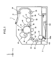
- FIG. 1 is a schematic view showing a configuration of a main part of an image forming apparatus according to Embodiment 1 of the present invention.
- an image forming apparatus 1 of Embodiment 1 has a configuration of, for example, an electrophotographic printer.
- a media cassette 2 for storing recording media 11 are detachably attached to a main body of the image forming apparatus 1.
- the recording media 11 are stacked and set in the media cassette 2.
- a supply roller 21 is provided in the image forming apparatus 1.
- the supply roller 21 cooperates with a separation frame 103 of the media cassette 2 to separately supply a recording medium 11 (from the recording media 11 stored in the media cassette 2) one by one.
- Feeding rollers 22, registration rollers 23 and eject rollers 25 and 26 are provided in the image forming apparatus 1, for feeding the recording medium 11 along a feeding path 24.
- An entering sensor 27, a passage sensor 28 and an ejection sensor 29 are provided in the image forming apparatus 1, for detecting the position of the recording medium 11 fed along the feeding path 24.
- An eject stacker 31 is provided on the image forming apparatus 1, which holds the ejected recording media 11.
- An image forming portion 3 is provided in the image forming apparatus 1, which forms a toner image (i.e., a developer image).
- a transfer roller 30 is provided in the image forming apparatus 1, which transfers the toner image to the recording medium 11.
- a fixing unit 4 is provided in the image forming apparatus 1, which fixes the toner image (having been transferred to the recording medium 11) to the recording medium 11.
- An image forming portion 3 for forming the toner image includes a photosensitive drum 41 for bearing the toner image, a charging roller 42 that uniformly charges the surface of the photosensitive drum 41, an exposing head 43 composed of LED array that form a latent image on the surface of the photosensitive drum 41, a developing unit 45 that stores toner (developer) and forms the toner image on the latent image using a developing roller 45, and a cleaning blade 46 that scrapes off the toner from the surface of the photosensitive drum 41 after the toner image is transferred to the recording medium 11.
- the fixing unit 4 includes a pair or rollers, i.e., a heat roller 51 having an internal heat source such as a halogen lamp (not shown) and a backup roller 52.
- the fixing unit 4 applies heat and pressure to the toner image on the recording medium 11 fed from the image forming portion 3 and the transfer roller 30 so that the toner image is molten and fixed to the recording medium 11.
- the recording media 11 set in the media cassette 2 are pressed by the supply roller 21 rotating in the direction shown by an arrow.
- the recording medium 11 is fed out of a placing plate 102, and is fed into the feeding path 24 one by one by the cooperation of the separation frame 103 (pushed by a not shown pushing unit clockwise about a shaft 103a) and the supply roller 21. Further, the recording medium 11 is fed by the feeding rollers 22 and reaches the detecting position of the entering sensor 27. In synchronization with the detection of the passage of the recording medium 11 by the entering sensor 27, the registration rollers 23 start rotating.
- the image forming portion 3 forms the toner image as follows. First, the surface of the photosensitive drum 41 rotating in a direction shown by an arrow is negatively charged by the charging roller 42. When the charged surface of the photosensitive drum 41 reaches the position below the exposing head 43, the exposing head 43 performs the exposure to form the latent image on the surface of the photosensitive drum 41. The latent image is developed by the developing roller 44 in the developing unit 45, and the toner image is formed. The toner image is transferred to the recording medium 11 by the transfer roller 30. The residual toner remaining on the surface of the photosensitive drum 41 is removed by the cleaning blade 46.
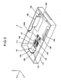
- FIGS. 2 and 3 are respectively a perspective view and a plan view of the media cassette as a media storage apparatus according to Embodiment 1 of the present invention.
- the side guides 104 and 105 moves along Y-axis in directions opposite to each other and in synchronization with each other. That is, the side guides 104 and 105 moves in the widthwise direction of the recording media 11 (i.e., the direction of the Y-axis) so that the side guides 104 and 105 are distanced from the center by the same amount, so as to symmetrically guide the recording media 11 with respect to the center of the placing plate 102.
- the tail guide 110 is provided for guiding the position of the recording media 11 set in the media cassette 2 in the longitudinal direction (i.e., the direction of the x-axis).
- the feeding side of the recording media 11 set in the media cassette 2 i.e., the negative side in the direction of the X-axis
- a front side i.e., the negative side in the direction of the X-axis
- the opposite side is referred to as a rear side.
- a movement-guide elongated hole 116 is formed on the bottom plate 115 of the cassette frame 101.
- the movement-guide elongated hole 116 extends from the rear end to the center in the feeding direction of the recording media 11.
- a plurality of first grooves 117 i.e., positioning portions
- a plurality of second grooves 118 are formed on both sides of the movement-guide elongated hole 116 in bilaterally symmetric manner.
- a side wall formed on the separation frame 103 side of the cassette frame 101 in the longitudinal direction constitutes a media reference surface 120 against which the front ends of the recording media 11 (i.e., the front end of the stack of the recording media 11) abut.
- the first grooves 117 are disposed at predetermined distances (described later) from the media reference surface 120.
- the second grooves 118 are formed at predetermined intervals to constitute groove-arrays 121 so that flat portions 119 lie between the groove-arrays 121 and the first grooves 117.
- the opening area of each first groove 117 is larger than the opening area of each second groove 118, and the depth of each first groove 117 is deeper than the depth of each second groove 118, so that claw portions 134 and 135 (FIG. 4) of the tail guide 110 can enter into the first groove 117 more deeply as described later.
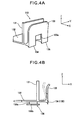
- FIG. 4A is a perspective view showing an external shape of the tail guide 110.
- FIG. 4B is a side view showing the tail guide 110.
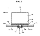
- FIG. 5 is a sectional view schematically showing the media cassette 2 taken along a line V-V shown in FIG. 3.
- the tail guide 110 includes a flat plate portion 132 on which the rear ends of the recording media 11 are placed facing the bottom plate 115 (FIG. 2) of the cassette frame 101, a media regulating plate 131 provided upright on the flat plate portion 132 so as to face the rear ends of the recording media 11 , a lock lever 133 with a parting portion 133a, and claw portions 134 and 135 protrude downward from both sides of the parting portion 133a of the lock lever 133 to positions lower than the flat plate portion 132.
- a suspended portion 136 is formed below the flat plate portion 132. As shown in FIG.
- the suspended portion 136 protrude downward from the bottom surface of the flat plate portion 132, and includes a guide convex 136a guided by the movement-guide elongated hole 116 of the cassette frame 101, and a bottom plate 136b formed continuously from the guide convex 136a for preventing the tail guide 110 from dropping out of the movement-guide elongated hole 116.
- the tail guide 110 is guided by the movement-guide elongated hole 116 and becomes slidably movable in the longitudinal direction thereof (i.e., the direction of X-axis).
- the claw portions 134 and 135 of the lock lever 133 engage the first grooves 117 or the second grooves 118 formed on the cassette frame 101, and are fixed at the engaging positions. Therefore, in order to move the tail guide 110, it is necessary to disengage the claw portions 134 and 135 from the first grooves 117 or the second grooves 118 by slightly lifting up the tail guide 110, or by pinching the lock lever 133 to inflect the lock lever 133 as shown by dashed line in FIG. 4B.
- the first grooves 117, the second grooves 118 and the flat portions 119 are arranged in the form of two arrays on both sides of the movement-guide elongated hole 116, and engage two claw portions 134 and 135 of the tail guide 110. Since the tail guide 110 is fixed on both (bilateral) sides of the movement-guide elongated hole 16, the tail guide 100 can be stably fixed.
- the positions of the first grooves 117 are so determined that the distance from the medium reference surface 120 to the medium regulation plate 131 of the tail guide 110 is, for example, the same as or slightly longer than the longer sides of the regular-sized recording media 11 (i.e., A3, A4, A5, B5 or the like of Japan Industrial Standard) so that the regular-sized recording media 11 can be suitably set, when the claw portions 134 and 135 of the tail guide 110 engage the first grooves 117 and are locked by the first grooves 117.
- the second grooves 118 are formed at narrower pitches than the first grooves 117, so that the second grooves 118 can be used for the irregular-sized recording media 11.
- the recording media 11 are stored in such a manner that the front ends of the recording media 11 abut against the media reference surface 120 (FIG. 3).
- the recording media 11 are guided by the side guides 104 and 105 in the widthwise direction, and the recording media 11 are guided in a symmetrical manner with respect to the center in the widthwise direction (i.e., the direction of the Y-axis).
- the tail guide 110 is moved to the position where the media regulating plate 131 of the tail guide 110 abuts against the rear ends of the recording media 11.
- the claw portions 134 and 135 (FIG. 5) of the tail guide 110 engage the first grooves 117 formed on the cassette frame 101 so that the tail guide 110 is fixed.
- the tail guide 110 it is also possible to push the rear ends of the recording media 11 by the tail guide 110 to the position where the front ends of the recording media 11 abut against the media reference surface 120. In this case, the tail guide 110 is fixed at the position where the front ends of the recording media 11 abut against the media reference surface 120. As another alternative method, it is also possible to previously fix the tail guide 110 at a fixing position corresponding to the regular-sized recording media 11, and then set the recording media 11 to a position defined between the media reference surface 120 and the tail guide 110.
- FIG. 6A shows the relationship among the claw portions 134 and 135, the first grooves 117 and the second grooves 118 in this state.
- the first grooves 117 engaging the claw portions 134 and 135 are deeper than the second grooves 118, and the flat portion 119 function as free areas in which the tail guide 110 can not be fixed. Therefore, it is easy to confirm that the tail guide 110 is fixed at the fixing position suitable for the regular-sized recording media 11.
- the width 119a of the flat portion 119 is wider than a width 118a of a portion between edges of the adjacent second grooves 118.
- the recording media 11 are stored in such a manner that the front ends of the recording media 11 abut against the media reference surface 120 (FIG. 3), as is the case with the regular-sized recording media 11. Then, the tail guide 110 is moved to the position (i.e., the contact position) where the media regulating plate 131 of the tail guide 110 abuts against the rear ends of the recording media 11, and the tail guide 110 is fixed at the closest position from the contact position.
- FIG. 6B shows the relationship among the claw portions 134 and 135, the first grooves 117 and the second grooves 118 in this state.
- the claw portions 134 and 135 engage the second grooves 118 of the groove-arrays 121 formed at narrow pitches, and therefore the accuracy in the fixing position can be enhanced.
- the first grooves 117, the second grooves 118 and the flat portions 119 are arranged in the form of two arrays on both sides of the movement-guide elongated hole 116.
- the tail guide defining the rear end of the recording media in the feeding direction can be positioned with a high positioning accuracy. Further, the free areas are provided ahead of and behind the first grooves (for the regular-sized recording media), and the first grooves are deeper than the second grooves for the irregular-sized recording media, with the result that it becomes easy to confirm the tail guide being fixed at the position for the regular-sized recording media. Moreover, during the setting of the irregular-sized recording media, the tail guide can be positioned with a high positioning accuracy.
- FIGS. 8 and 9 are a perspective view and a plan view showing a configuration of a media cassette as a media storage apparatus according to Embodiment 2 of the present invention.
- the media cassette 202 according to Embodiment 2 is mainly different from the above described media cassette 2 according to Embodiment 1 (FIG. 2) in the shapes of the grooves formed on the bottom plate 115 and the claw portions of a tail guide 210 (in contrast with the tail guide 110 in Embodiment 1) that engage the grooves.
- Elements of the media cassette 202 that are the same as those of the media cassette 2 are assigned the same reference numerals, and duplicate explanation will be omitted.
- the description will be emphasized on the difference between the media cassette 202 and the media cassette 2.
- the main body of the image forming apparatus to which the media cassette 202 is attached is the same as the main body (i.e., except the media cassette 2) of the image forming apparatus 1 shown in FIG. 1, and therefore duplicate explanation will be omitted.
- the media cassette 202 detachably attached to the image forming apparatus 1 includes a cassette frame 101 for storing the recording media 11 (FIG. 1), a placing plate 102 supported by the cassette frame 101 and rotatable about an axis 102a in the direction of the Y-axis, a separation frame 103 having the above described structure, and the tail guide 210 described later.
- a pair of side guides 104 and 105 are disposed on the placing plate 102 for setting the recording media 11.
- the side guides 104 and 105 are supported on the placing plate 102 so that the side guides 104 and 105 are slidable in the direction of the Y-axis.
- the side guides 104 and 105 have rack gears 104a and 105a at the backside of the placing plate 102 that engage the pinion gear 106 (rotatably formed by the placing plate 102) where the side guides 104 and 105 face each other.
- the side guides 104 and 105 moves in directions opposite to each other along the Y-axis and in synchronization with each other, so as to symmetrically guide the recording media 11 with respect to the center of the placing plate 102 in the widthwise direction (i.e., the direction of the Y-axis).
- the tail guide 210 is provided for guiding the position of the recording media 11 set in the media cassette 202 in the longitudinal direction (i.e., the direction of the X-axis).
- a movement-guide elongated hole 116 is formed on the bottom plate 115 of the cassette frame 101, and extends from the rear end to the center in the feeding direction of the recording media 11.
- First grooves 117, second grooves 118 and third grooves 217 are formed on the bottom plate 115.
- the first grooves 117, the second grooves 118 and the third grooves 217 have different shapes.
- the first grooves 117 are formed on one side of the movement-guide elongated hole 116.
- the second grooves 118 and the third grooves 217 are formed on the other side of the movement-guide elongated hole 116.
- the shapes of the first grooves 117 and the second grooves 118 are as described in Embodiment 1. As shown in FIG.
- each first groove 117 is larger than the opening area of each second groove 118, and the depth of each first groove 117 is deeper than the depth of each second groove 118.
- the depth of each third groove 217 is substantially the same as the depth of each second groove 118, and the width of each third groove 217 is substantially the same as or wider than the width of each first groove 117.
- a side wall formed on the separation frame 103 side of the cassette frame 101 in the longitudinal direction constitutes a media reference surface 120 against which the front ends of the recording media 11 abut.
- the first grooves 117 are disposed at predetermined distances (described later) from the media reference surface 120.
- the third grooves 217 are formed to face the first grooves 117 via the movement-guide elongated hole 116.
- the second grooves 118 are continuously formed at predetermined intervals to constitute groove-arrays 121.
- the second grooves 118 (the groove-arrays 121) are formed on areas with no third grooves 217, and are aligned in the same array with the third grooves 217.
- FIG. 10 is a perspective view showing the external shape of the tail guide 210.
- the tail guide 210 includes claw portions 234 and 135 formed on the bottom of a lock lever 233.
- the claw portions 234 and 135 protrude downward from both sides of a parting portion 233a of the bottom of the lock lever 233 to a lower position than the flat plate portion 132.
- the protruding amount of the claw portion 234 is smaller than that of the protruding amount of the claw portion 135.
- the claw portion 234 engages the second groove 118 or the third groove 217 which are shallower than the first groove 117.
- the claw portion 135 engages the first groove 117 deeper than the second and third grooves.
- the other configuration of the tail guide 210 is the same as that of the tail guide 110 of Embodiment 1 (FIG. 4), and therefore duplicate explanation will be omitted.
- the tail guide 210 is guided by the movement-guide elongated hole 116 formed on the cassette frame 101 and becomes slidably movable in the longitudinal direction thereof (i.e., the direction of X-axis).
- the claw portion 135 of the lock lever 233 engages the first groove 117 of the cassette frame 101 and the claw portion 234 of the lock lever 233 enters into the third groove 217, or the claw portion 234 engages the second groove 118 of the cassette frame 101, so that the tail guide 210 are fixed at engaging position.
- the positions of the first groove 117 are so determined that the distance from the medium reference surface 120 to the medium regulation plate 131 of the tail guide 210 is, for example, the same as or slightly longer than the longer sides of the regular-sized recording media 11 (i.e., A3, A4, A5, B5 or the like of Japan Industrial standard) so the regular-sized recording media 11 can be suitably set, in a state where the claw portion 135 of the tail guide 210 engages the first groove 117 and is locked by the first groove 117.
- the second grooves 118 are formed at narrower pitches than the first grooves 117 so that the second grooves 118 can be used for the irregular-sized recording media.
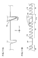
- FIG. 11A is a sectional view of a part in which the first grooves 117 are formed, as seen from the negative side in the direction of the Y-axis.
- FIG. 11B is a sectional view of a part in which the second grooves 118 and the third grooves 217 are formed, as seen from the negative side in the direction of the Y-axis.
- the respective grooves of FIGS. 11A and 11B show the respective positions in the direction of the X-axis.
- FIGS. 12A and 12B are illustrated in the same way as FIGS. 11A and 11B.
- the recording media 11 are stored in such a manner that the front ends of the recording media 11 abut against the media reference surface 120 (FIG. 9).
- the recording media 11 are guided by the pair of side guides 104 and 105 in the widthwise direction, and the recording media 11 are guided in a symmetrical manner with respect to the center in the widthwise direction (i.e., the direction of the Y-axis).
- the tail guide 210 is moved to the position where the media regulating plate 131 of the tail guide 210 abuts against the rear ends of the recording media 11.
- the claw portion 135 (FIG. 9) of the tail guide 210 engages the first groove 117 formed on the cassette frame 101 so that the tail guide 210 is fixed.
- the tail guide 210 it is also possible to push the rear ends of the recording media 11 by the tail guide 210 to the position where the front ends of the recording media 11 abut against the media reference surface 120. In this case, the tail guide 210 is fixed at a position where the front ends of the recording media 11 abut against the media reference surface 120. As another alternative method, it is also possible to previously fix the tail guide 210 at a fixing position corresponding to the regular-sized recording media 11, and then set the recording media 11 to the position defined between the media reference surface 120 and the tail guide 210.
- FIG. 11A shows the relationship between the claw portion 135 and the first grooves 117 in this state.
- FIG. 11B shows the relationship among the claw portion 234, the second grooves 117 and the third grooves 217 in this state.
- the claw portion 135 engages the first groove 117, and the claw portion 234 enters into the third groove 217.
- the width 217a of the third groove 217 is wider than the width of the upper end of the first groove 117, so that the claw portion 234 is allowed to freely move over the engaging position where the claw portion 135 engages the first groove 117 and the vicinity (frontward and rearward) of the engaging position.
- the recording media 11 are stored in such a manner that the front ends of the recording media 11 abut against the media reference surface 120 (FIG. 9), as is the case with the regular-sized recording media. Then, the tail guide 210 is moved to the position (i.e., the contact position) where the media regulating plate 131 of the tail guide 210 abuts against the rear ends of the recording media 11, and the tail guide 210 is fixed at the closest position from the contact position.
- FIG. 12A shows the relationship between the claw portion 135 and the first grooves 117 in this state.
- FIG. 12B shows the relationship among the claw portion 234, the second grooves 118 and the third grooves 217 in this state.
- the claw portion 234 engages the second grooves 118, and the claw portion 135 is in a free state.
- the claw portion 234 engages the second grooves 118 of the groove-arrays 121 formed at narrow pitches, and therefore the accuracy in the fixing position can be enhanced.
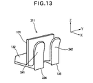
- FIG. 13 shows another configuration example of the tail guide 210.
- the claw portions 234 and 135 are formed as lock levers 241 and 242 formed separately from each other. It is also possible to employ the tail guides 211 having the structure shown in FIG. 13 instead of the above described tail guide 210. By employing the tail guides 211 of such structure, the engaging operation of the claw portion 234 and the second groove 118 and the engaging operation of the claw portion 135 and the first groove 117 can be performed independently from each other.
- the tail guide can be fixed by means of the engagement between the claw portion and the groove at one position, and therefore the operability of the tail guide can be enhanced. Further, during the setting of the regular-sized recording media, the tail guide is in the free-state at positions ahead of and behind the fixing position, and therefore it becomes easy to confirm that the tail guide being fixed at the position for the regular-sized recording media. Furthermore, during the setting of the irregular-sized recording media, the tail guide can be fixed with a high positioning accuracy.
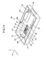
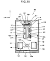
- FIGS. 14 and 15 are respectively a perspective view and a plan view showing a configuration of a media cassette as a media storage apparatus according to Embodiment 3 of the present invention.
- the media cassette 302 according to Embodiment 3 is mainly different from the above described media cassette 202 according to Embodiment 2 shown in FIG. 8 in that fourth grooves 317 (engaging grooves) are formed on the bottom plate 115 and aligned in the same array as the first grooves 117.
- fourth grooves 317 engaging grooves
- Elements of the media cassette 302 that are the same as those of the media cassette 202 are assigned the same reference numerals, and duplicate explanation will be omitted.
- the description will be emphasized on the difference between the media cassette 302 and the media cassette 202.
- the main body of the image forming apparatus to which the media cassette 302 is attached is the same as the main body (i.e., except the media cassette 2) of the image forming apparatus 1 shown in FIG. 1, and therefore duplicate explanation will be omitted.
- the tail guide 210 and a holding mechanism thereof will be described.
- the tail guide 210 is provided for guiding the position of the recording media 11 set in the media cassette 302 in the longitudinal direction (i.e., the direction of the X-axis).
- a movement-guide elongated hole 116 is formed on the bottom plate 115 of the cassette frame 101, and extends from the rear end to the center in the feeding direction of the recording media 11.
- First grooves 117, second grooves 118, third grooves 217 and fourth grooves 317 are formed on the bottom plate 115.
- the first grooves 117, the second grooves 118, the third grooves 217 and the fourth grooves 317 have different shapes.
- the first grooves 117 and the fourth grooves 317 are formed on one side of the movement-guide elongated hole 116.
- the second grooves 118 and the third grooves 217 are formed on the other side of the movement-guide elongated hole 116.
- the shapes of the first grooves 117 and the second grooves 118 are as described in Embodiment 1. As shown in FIG. 16 (described later), the opening area of each first groove 117 is larger than the opening area of each second groove 118, and the depth of each first groove 117 is deeper than the depth of each second groove 118.
- the depth of each third groove 217 is substantially the same as the depth of each second groove 118, and the width of each third groove 217 is substantially the same as or wider than the width of each first groove 117.
- the depth of each fourth groove 317 is substantially the same as or deeper than the depth of each first groove 117, and the width of each fourth groove 317 is substantially the same as or wider than the width of each second groove 118 (i.e., the groove-array 121).
- the positions of the first grooves 117, the second grooves 118 and the third grooves 217 are as described in Embodiment 2, and therefore duplicate explanation will be omitted.
- the fourth grooves 317 are formed on areas with no first grooves 117 (i.e., positions facing the groove-arrays 121 via the movement-guide elongated hole 116) and are aligned in the same array with the first grooves 117.
- the fourth grooves 317 have the widths substantially the same as or wider than the second grooves 181, i.e., groove-arrays 121.
- FIG. 16A is a sectional view of a part in which the first grooves 117 and the fourth grooves 317 are formed, as seen from the negative side in the direction of the Y-axis.
- FIG. 16B is a sectional view of a part in which the second grooves 118 and the third grooves 217 are formed, as seen from the negative side in the direction of the Y-axis.
- the respective grooves of FIGS. 16A and 16B show the respective positions in the direction of the X-axis.
- FIGS. 17A and 17B are illustrated in the same way as FIGS. 16A and 16B.
- the recording media 11 are stored in such a manner that the front ends of the recording media 11 abut against the media reference surface 120 (FIG. 15).
- the recording media 11 are guided by the pair of side guides 104 and 105 in the widthwise direction, and the recording media 11 are guided in a symmetrical manner with respect to the center in the widthwise direction (i.e., the direction of the Y-axis).
- the tail guide 210 is moved to the position where the media regulating plate 131 of the tail guide 210 abuts against the rear ends of the recording media 11.
- the claw portion 135 (FIG. 15) of the tail guide 210 engages the first groove 117 formed on the cassette frame 101 so that the tail guide 210 is fixed.
- the tail guide 210 it is also possible to push the rear ends of the recording media 11 by the tail guide 210 to the position where the front ends of the recording media 11 abut against the media reference surface 120. In this case, the tail guide 210 is fixed at a position where the front ends of the recording media 11 abut against the media reference surface 120. As another alternative method, it is also possible to previously fix the tail guide 210 at a fixing position corresponding to the regular-sized recording media, and then set the recording media 11 to the position defined between the media reference surface 120 and the tail guide 210.
- FIG. 16A shows the relationship among the claw portion 135, the first grooves 117 and the fourth grooves 317 in this state.
- FIG. 16B shows the relationship among the claw portion 234, the second grooves 118 and the third grooves 217 in this state.
- the claw portion 135 engages the first groove 117
- the claw portion 234 enters into the third groove 217.
- the third groove 217 has the sufficient width to allow the claw portion 234 to freely move over the engaging position where the claw portion 135 engages the first groove 117 and the vicinity (frontward and rearward) of the engaging position.
- the recording media 11 are stored in such a manner that the front ends of the recording media 11 abut against the media reference surface 120 (FIG. 15), as is the case with the regular-sized recording media. Then, the tail guide 210 is moved to the position (i.e., the contact position) where the media regulating plate 131 of the tail guide 210 abuts against the rear ends of the recording media 11, and the tail guide 210 is fixed at the closest position from the contact position.
- FIG. 17A shows the relationship among the claw portion 135, the first grooves 117 and the fourth grooves 317 in this state.
- FIG. 17B shows the relationship among the claw portion 234, the second grooves 118 and the third grooves 217 in this state.
- the claw portion 234 engages the second groove 118, and the claw portion 135 enters into the fourth groove 317.
- the fourth groove 317 has the sufficient width to allow the claw portion 135 to freely move when the claw portion 234 engages the second groove 118 (i.e., the groove-array 121).
- the claw portion 234 engages the second groove 118 of the groove-array 121 formed at narrow pitches, and therefore the accuracy in the fixing position can be enhanced. Furthermore, during the setting of the irregular-sized recording media 11, it is only necessary that the claw portion 234 engages the second groove 118 at one position, and therefore the operability of the tail guide 210 can be enhanced.
- the tail guide can be fixed by means of the engagement between the claw portion and the groove at one position, and therefore the operability of the tail guide can be enhanced. Further, during the setting of the regular-sized recording media, the tail guide is in the free-state at positions ahead of and behind the fixing position, and therefore it becomes easy to confirm the tail guide being fixed at the position for the regular-sized recording media. Furthermore, during the setting of the irregular-sized recording media, the tail guide can be fixed with a high positioning accuracy. Moreover, when the tail guide is fixed, the deformation (distortion or the like) of the lock lever of the tail guide hardly occurs, and therefore the operability can be further enhanced.
- FIGS. 18 and 19 are respectively a perspective view and a plan view showing a configuration of a media cassette as a media storage apparatus according to Embodiment 4 of the present invention.
- the media cassette 402 according to Embodiment 4 is mainly different from the above described media cassette 2 according to Embodiment 1 (FIG. 2) in the shapes of the grooves formed on the bottom plate 115 and the structure of the tail guide 410 (in contrast with the tail guide 110 of Embodiment 1).
- Elements of the media cassette 402 that are the same as those of the media cassette 2 of Embodiment 1 are assigned the same reference numerals, and duplicate explanation will be omitted.
- the description will be emphasized on the difference between the media cassette 402 and the media cassette 2.
- the main body of the image forming apparatus to which the media cassette 402 is attached is the same as the main body (i.e., except the media cassette 2) of the image forming apparatus 1 shown in FIG. 1, and therefore duplicate explanation will be omitted.
- the tail guide 410 and a holding mechanism thereof will be described.
- the tail guide 410 is provided for guiding the position of the recording media 11 set in the media cassette 402 in the longitudinal direction (i.e., the direction of the X-axis).
- a movement-guide elongated hole 116 is formed on the bottom plate 115 of the cassette frame 101, and extends from the rear end to the center in the feeding direction of the recording media 11.
- First grooves 117 and second grooves 118 having different shapes are formed on the bottom plate 115.
- the first grooves 117 are formed on one side of the movement-guide elongated hole 116.
- the second grooves 118 are formed on the other side of the movement-guide elongated hole 116.
- the shapes of the first grooves 117 and the second grooves 118 are as described in Embodiment 1.
- the opening area of each first groove 117 is larger than the opening area of each second groove 118, and the depth of each first groove 117 is deeper than the depth of each second groove 118.
- a side wall formed on the separation frame 103 side of the cassette frame 101 in the longitudinal direction constitutes a media reference surface 120 against which the front ends of the recording media 11 abut.
- the first grooves 117 are disposed at predetermined distances from the media reference surface 120.
- the second grooves 118 are continuously formed at predetermined intervals and form groove-arrays 421.
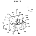
- FIG. 20 is a perspective view showing the external shape of the tail guide 410.
- the tail guide 410 includes a sliding member 455 and a sliding member 456 both of which are slidable in the vertical direction.
- the sliding member 455 has a claw portion 455a formed on the bottom thereof, and the sliding member 456 has a claw portion 456a formed on the bottom thereof.
- the sliding members 455 and 456 are adjacent to each other, and supported by not shown guiding units so that the sliding members 455 and 456 are slidable in the vertical direction (i.e., the direction of the Z-axis).
- a movable member (lever) 451 is supported by the tail guide 410 so that the movable member 451 is rotatable about the rotation axis parallel to the X-axis.
- the movable member 451 has a shaft portion 451a, operation arms 451c and 451d projecting from the shaft portion 451a in the opposite directions, and a lock arm 451b extending from the shaft portion 451a in the direction perpendicular to the operation arms 451c and 451d.
- a coil spring 453 is provided between the operation arm 451c and the sliding member 455.
- a coil spring 454 is provided between the operation arm 451d and the sliding member 456.
- a protrusion 452 is provided on the media regulating plate 131.
- the protrusion 452 has a spherical portion with a flat end 452a.
- the protrusion 452 is pushed in the positive direction along X-axis by a not shown pushing unit so that the spherical portion (having the flat end 452a) protrudes from the backside of the media regulating plate 131 to the position where the protrusion 452 contacts the lock arm 451b. Further movement of the protrusion 452 in the direction of the X-axis is restricted.
- the other configuration (i.e., the suspended portion 136 (FIG. 4) or the like) of the tail guide 410 is the same as the tail guide 110 (FIG. 4) described in Embodiment 1, and therefore duplicate explanation will be omitted.
- the tail guide 410 is guided by the movement-guide elongated hole 116 formed on the cassette frame 101 and becomes slidably movable in the longitudinal direction thereof (i.e., the direction of X-axis).
- the claw portion 455a of the sliding member 455 of the tail guide 410 engages the second groove 118, or the claw portion 456a of the sliding member 456 of the tail guide 410 engages the first groove 117, so that the tail guide 410 is fixed.
- the fixing operation will be described with reference to FIGS. 21A, through 21C.
- FIGS. 21A through 21C are schematic views illustrating the operation for fixing the tail guide 410.
- the movable member 451 when the movable member 451 is in a neutral position (i.e., upright position) where the lock arm 451b contacts the flat end 452a and pushes in the protrusion 452, both of the claw portion 455a of the sliding member 455 and the claw portion 456a of the sliding member 456 are retracted in the tail guide 410.
- the tail guide 410 can freely move along the movement-guide elongated hole 116.
- a restricting unit (not shown).
- the respective strengths of the coil spring 453 and the pushing unit (not shown) of the protrusion 452 are so set that the clockwise rotation of the lock arm 451b of the movable member 451 is prevented by the protrusion 452 (pushed by the not shown pushing unit) when the lock arm 451b is pushed by the counterforce of the coil spring 453, and that the rotation of the movable member 451 is allowed when the user manually rotates the movable member 451 to the neutral position (FIG. 21A).
- the protrusion 452 protrudes and regulates the counterclockwise rotation of the movable member 451.
- the operation arm 451d pushes the coil spring 454 downward
- the coil spring 454 in a compressed state
- the claw portion 456a of the sliding member 456 protrudes downward, and becomes engagable with the first grooves 117.
- the sliding member 455 is pushed upward by the coil spring 453 (in an expanded state).
- a restricting unit (not shown).
- the respective strengths of the coil spring 454 and the pushing unit (not shown) of the protrusion 452 are so set that the counterclockwise rotation of the lock arm 451b of the movable member 451 is prevented by the protrusion 452 (pushed by the not shown pushing unit) when the lock arm 451b of the movable member 451 is pushed by the counterforce of the coil spring 454, and that the rotation of the movable member 451 is allowed when the user manually rotates the movable member 451 to the neutral position (FIG. 21A).
- the respective protruding amounts of the claw portions 455a and 456a are set according to the depths of the second grooves 118 and the first grooves 117 which the claw portions 455a and 456a respectively engage.
- the protruding amount of the claw portion 456a is larger than the protruding amount of the claw portion 455a.
- the movable member 451, the protrusion 452, the coil springs 453 and 454 and the like constitute a switching mechanism of the claw portions 455a and 456a.
- the positions of the first grooves 117 are so determined that the distance from the medium reference surface 120 to the medium regulation plate 131 of the tail guide 410 is, for example, the same as or slightly longer than the longer sides of the regular-sized recording media 11 (such as A3, A4, A5, B5 or the like of Japan Industrial Standard) so that the regular-sized recording media 11 can be suitably set, when the claw portion 456a of the sliding member 456 engage the above described first groove 117 and is locked.
- the second grooves 118 are formed at narrower pitches than the first grooves 117.
- the recording media 11 are stored in such a manner that the front ends of the recording media 11 abut against the media reference surface 120 (FIG. 15).
- the recording media 11 are guided by the pair of side guides 104 and 105 in the widthwise direction, and the recording media 11 are guided in a symmetrical manner with respect to the center in the widthwise direction (i.e., the direction of the Y-axis).
- the tail guide 410 is moved to the position where the media regulating plate 131 of the tail guide 410 abuts against the rear ends of the recording media 11.
- the movable member 451 of the tail guide 400 is held at the neutral position (FIG. 21A).
- the movable member 451 is rotated clockwise to the right inclined position shown in FIG. 21C so that the claw portion 456a engages the first groove 117 to fix the tail guide 410.
- the tail guide 410 it is also possible to push the rear ends of the recording media 11 by the tail guide 410 to the position where the front ends of the recording media 11 abut against the media reference surface 120. In this case, the tail guide 410 is fixed at a position where the front ends of the recording media 11 abut against the media reference surface 120. As another alternative method, it is also possible to previously fix the tail guide 410 at a fixing position corresponding to the regular-sized recording media, and then set the recording media 11 to a position defined between the media reference surface 120 and the tail guide 410.
- the recording media 11 are stored in such a manner that the front ends of the recording media 11 abut against the media reference surface 120 (FIG. 15), as is the case with the regular-sized recording media. Then, the tail guide 410 is moved to the position (i.e., the contact position) where the media regulating plate 131 of the tail guide 410 abuts against the rear ends of the recording media 11, and the tail guide 410 is fixed at the closest position from the contact position. During the movement of the tail guide 410, the movable member 451 of the tail guide 400 is held at the neutral position (FIG. 21A). After the movement, the movable member 451 is rotated counterclockwise to the left inclined position shown in FIG.
- the claw portion 455a engages the second groove 118 to fix the tail guide 410.
- the claw portion 455a engages the second grooves 118 of the groove-arrays 421 formed at narrow pitches, and therefore the accuracy in the fixing position can be enhanced.
- the tail guide 410 can be fixed to the cassette frame 101 by means of the engagement between the claw portion and the groove at one position, in either case of setting the regular-sized recording media 11 and setting the irregular-sized recording media 11.
- the first grooves 117 and the second grooves 118 whose shapes are different from each other are formed on both sides of the movement-guide elongated hole 116.
- the shapes (i.e., the opening areas and depths) of the first grooves 117 and the second grooves 118 are the same as each other.
- the tail guide can be fixed by means of the engagement between the claw portion and the groove at one position, and therefore the operability of the tail guide can be enhanced. Further, when one of two sliding members (provided adjacent to each other) engages the groove, the other of the sliding members is surely retracted in the tail guide, and therefore the fixing operation can be surely performed.
- the media storage apparatus and the image forming apparatus according to the present invention are applied to the electrophotographic printer.
- the present invention can also be applied to an MFP (Multi Function Printer), a facsimile, or a copier. Further, the present invention can also be applied to a two-stage tray or a multistage tray.
Landscapes
- Physics & Mathematics (AREA)
- General Physics & Mathematics (AREA)
- Engineering & Computer Science (AREA)
- Mechanical Engineering (AREA)
- Sheets, Magazines, And Separation Thereof (AREA)
Abstract
Description
- This invention relates to an image forming apparatus such as an electrophotographic printer, a facsimile, a copier or the like. In particular, this invention relates to a media storage apparatus for storing recording media used in the image forming apparatus.
- Conventionally, a sheet cassette of an image forming apparatus has a sheet guiding mechanism for guiding the sheets. The sheet guiding mechanism includes, for example, a sheet rear end guide that guides the rear end of recording media. The sheet rear end guide engages one of grooves formed at constant intervals on a bottom frame of the sheet cassette so that the position of the sheet rear end guide is determined. Such a sheet cassette is disclosed in, for example,
Japanese Laid-Open Patent Publication No. 8-34525 - In the above described conventional sheet cassette, if the grooves are formed at narrow intervals, the sheet rear end guide can be fixed at a substantially arbitrary position. Therefore, the sheet rear end guide is capable of guiding various kind of irregular-sized sheets in accordance with the needs of the user, as well as regular-sized sheets such as A4, A3 or the like. However, if the intervals between the grooves become narrower, it becomes difficult to identify the best-suited fixing position. In such a case, even when the regular-sized sheets such as A4, A3 or the like are set in the sheet cassette, it is difficult to fix the sheet rear end guide at a predetermined (best-suited) fixing position.
- An object of the present invention is to provide a media storage apparatus and an image forming apparatus in which a guide member can be easily positioned when regular-sized recording media (A4 size, A3 size or the like) are set, and in which the guide member can be used to guide irregular-sized recording media.
- The present invention provides a media storage apparatus including a media storing body that stores recording media, a guide member slidably provided in the media storing body and guiding the recording media, a first positioning portion that positions the guide member at a predetermined position where the guide member guides regular-sized recording media, and a second positioning portion that positions the guide member at a position where the guide member guides irregular-sized recording media. The first positioning portion and the second positioning portion have different shapes.
- The present invention also provides a media storage apparatus including a media storing body that stores recording media, a guide member slidably provided in the media storing body and guiding the recording media, a first positioning portion that positions the guide member at a predetermined position where the guide member guides regular-sized recording media, and a second positioning portion that positions the guide member at a position where the guide member guides irregular-sized recording media. The guide member includes a first claw portion that engages the first positioning portion, a second claw portion that engages the second positioning portion, and a switching mechanism that selectively causes one of the first and second claw portions to engage corresponding one of the first and second positioning portions.
- The present invention also provides an image forming apparatus including the above described media storage apparatus, an image forming portion that forms a developer image, a transferring portion that transfers the developer image to a recording medium fed from the media storing portion, a fixing portion that fixes the developer image to the recording medium.
- With such an arrangement, the guide member can be easily positioned when the regular-sized recording media are set in the media storing body, and the guide member can be positioned with a high positioning accuracy when the irregular-sized recording media are set in the media storing body.
- In the attached drawings:
- FIG. 1 is a schematic view showing a configuration of a main part of an image forming apparatus according to Embodiment 1 of the present invention;
- FIG. 2 is a perspective view showing a configuration of a media cassette as a media storage apparatus according to Embodiment 1 of the present invention;
- FIG. 3 is a plan view showing a configuration of the media cassette according to Embodiment 1 of the present invention;
- FIG. 4A is a perspective view showing an external shape of a tail guide according to Embodiment 1 of the present invention;
- FIG. 4B is a side view showing the tail guide according to Embodiment 1 of the present invention;
- FIG. 5 is a sectional view schematically showing the media cassette taken along line V-V shown in FIG. 3;
- FIG. 6A shows a relationship among a claw portion, a first groove and a second groove when regular-sized recording media are set in the media cassette;
- FIG. 6B shows a relationship among the claw portion, the first groove and the second groove when irregular-sized recording media are set in the media cassette;
- FIG. 7 shows another configuration example of the tail guide according to Embodiment 1 of the present invention;
- FIG. 8 is a perspective view showing a configuration of a media cassette as a media storage apparatus according to
Embodiment 2 of the present invention; - FIG. 9 is a plan view showing a configuration of a tail guide according to
Embodiment 2 of the present invention; - FIG. 10 is a perspective view showing an external shape of the tail guide according to
Embodiment 2; - FIG. 11A shows a relationship between a claw portion and a first groove when regular-sized recording media are set in the media cassette;
- FIG. 11B shows a relationship among the claw portion, a second groove and a third groove when regular-sized recording media are set in the media cassette;
- FIG. 12A shows a relationship between the claw portion and the first groove when irregular-sized recording media are set in the media cassette;
- FIG. 12B shows a relationship among the claw portion, the second groove and the third groove when irregular-sized recording media are set in the media cassette;
- FIG. 13 shows another configuration example of the tail guide according to
Embodiment 2; - FIG. 14 is a perspective view showing a configuration of a media cassette as a media storage apparatus according to
Embodiment 3 of the present invention; - FIG. 15 is a plan view showing a configuration of the media cassette according to
Embodiment 3 of the present invention; - FIG. 16A shows a relationship among a claw portion, a first groove and a fourth groove when regular-sized recording media are set in the media cassette;
- FIG. 16B shows a relationship among the claw portion, a second groove and a third groove when regular-sized recording media are set in the media cassette;
- FIG. 17A shows a relationship among the claw portion, the first groove and the fourth groove when irregular-sized recording media are set in the media cassette;
- FIG. 17B shows a relationship among the claw portion, the second groove and the third groove when irregular-sized recording media are set in the media cassette;
- FIG. 18 is a perspective view showing a configuration of a media cassette as a media storage apparatus according to Embodiment 4 of the present invention;
- FIG. 19 is a plan view showing a configuration of the media cassette according to Embodiment 4 of the present invention;
- FIG. 20 is a perspective view showing an external shape of a tail guide according to Embodiment 4;
- FIGS. 21A through 21C are schematic views for illustrating the operation of the tail guide according to Embodiment 4, FIG. 21A shows the state where a movable member is at a neutral position, FIG. 21B shows the state where a claw portion protrudes downward to become engagable with one of second grooves, and FIG. 21C shows the state where another claw portion protrudes downward to become engagable with one of first grooves.
- Embodiments of the present invention will be described with reference to the attached drawings.
- FIG. 1 is a schematic view showing a configuration of a main part of an image forming apparatus according to Embodiment 1 of the present invention.
- In FIG. 1, an image forming apparatus 1 of Embodiment 1 has a configuration of, for example, an electrophotographic printer. As shown in FIG. 1, a
media cassette 2 for storingrecording media 11 are detachably attached to a main body of the image forming apparatus 1. Therecording media 11 are stacked and set in themedia cassette 2. The detail of themedia cassette 2 will be described later. Asupply roller 21 is provided in the image forming apparatus 1. Thesupply roller 21 cooperates with aseparation frame 103 of themedia cassette 2 to separately supply a recording medium 11 (from therecording media 11 stored in the media cassette 2) one by one. Feedingrollers 22,registration rollers 23 and ejectrollers recording medium 11 along a feedingpath 24. An enteringsensor 27, apassage sensor 28 and anejection sensor 29 are provided in the image forming apparatus 1, for detecting the position of therecording medium 11 fed along the feedingpath 24. Aneject stacker 31 is provided on the image forming apparatus 1, which holds the ejectedrecording media 11. Animage forming portion 3 is provided in the image forming apparatus 1, which forms a toner image (i.e., a developer image). Atransfer roller 30 is provided in the image forming apparatus 1, which transfers the toner image to therecording medium 11. A fixing unit 4 is provided in the image forming apparatus 1, which fixes the toner image (having been transferred to the recording medium 11) to therecording medium 11. - An
image forming portion 3 for forming the toner image includes aphotosensitive drum 41 for bearing the toner image, a chargingroller 42 that uniformly charges the surface of thephotosensitive drum 41, an exposinghead 43 composed of LED array that form a latent image on the surface of thephotosensitive drum 41, a developingunit 45 that stores toner (developer) and forms the toner image on the latent image using a developingroller 45, and acleaning blade 46 that scrapes off the toner from the surface of thephotosensitive drum 41 after the toner image is transferred to therecording medium 11. - The fixing unit 4 includes a pair or rollers, i.e., a
heat roller 51 having an internal heat source such as a halogen lamp (not shown) and abackup roller 52. The fixing unit 4 applies heat and pressure to the toner image on therecording medium 11 fed from theimage forming portion 3 and thetransfer roller 30 so that the toner image is molten and fixed to therecording medium 11. - FIG. 1 shows XYZ-coordinate. X-axis is defined in a feeding direction of the
recording medium 11 when therecording medium 11 passes theimage forming portion 3. Y-axis is defined in a direction of a rotation axis of thephotosensitive drum 41. Z-axis is defined in a direction perpendicular to the X-axis and the Y-axis. When the XYZ-coordinate is shown in other drawings, the X-axis , the Y-axis and the Z-axis respectively show the same direction as those shown in FIG. 1. In other words, the X-axis, the Y-axis and the Z-axis of the respective drawings indicate the direction of respective parts when the parts constitute the image forming apparatus 1 shown in FIG. 1. - Next, the printing operation of the image forming apparatus 1 will be described. The
recording media 11 set in themedia cassette 2 are pressed by thesupply roller 21 rotating in the direction shown by an arrow. Therecording medium 11 is fed out of aplacing plate 102, and is fed into the feedingpath 24 one by one by the cooperation of the separation frame 103 (pushed by a not shown pushing unit clockwise about ashaft 103a) and thesupply roller 21. Further, therecording medium 11 is fed by the feedingrollers 22 and reaches the detecting position of the enteringsensor 27. In synchronization with the detection of the passage of therecording medium 11 by the enteringsensor 27, theregistration rollers 23 start rotating. The skew of therecording medium 11 is corrected by theregistration rollers 23, and then therecording medium 11 reaches the detecting position of thepassage sensor 28. In synchronization with detection of the passage of therecording medium 11 by thepassage sensor 28, theimage forming portion 3 starts forming the toner image. The toner image formed on the surface of thephotosensitive drum 41 is transferred to the recording medium 11 (having been fed) by thetransfer roller 30. - The
image forming portion 3 forms the toner image as follows. First, the surface of thephotosensitive drum 41 rotating in a direction shown by an arrow is negatively charged by the chargingroller 42. When the charged surface of thephotosensitive drum 41 reaches the position below the exposinghead 43, the exposinghead 43 performs the exposure to form the latent image on the surface of thephotosensitive drum 41. The latent image is developed by the developingroller 44 in the developingunit 45, and the toner image is formed. The toner image is transferred to therecording medium 11 by thetransfer roller 30. The residual toner remaining on the surface of thephotosensitive drum 41 is removed by thecleaning blade 46. - The toner image (having been transferred to the
recording medium 11 by the transfer roller 30) is fixed to therecording medium 11 by the fixing process at high temperature and high pressure applied by theheat roller 51 and thebackup roller 52 of the fixing unit 4. Therecording medium 11 to which the toner image is fixed by the fixing process is ejected by theeject rollers eject stacker 31. The ejection of therecording medium 11 is detected by theejection sensor 29. - Next, the
media cassette 2 will be described. FIGS. 2 and 3 are respectively a perspective view and a plan view of the media cassette as a media storage apparatus according to Embodiment 1 of the present invention. - As shown in FIGS. 2 and 3, the
media cassette 2 detachably attached to the main body of the image forming apparatus 1 includes acassette frame 101 as a media storing body for storing the recording media 11 (FIG. 1), and aplacing plate 102 supported by thecassette frame 101 so that the placingplate 102 is rotatable about anaxis 102a parallel to the Y-axis. The placingplate 102 pushes therecording media 11 placed thereon against the supply roller 21 (FIG. 1) by means of a not-shown pushing unit. Themedia cassette 2 further includes the above describedseparation frame 103 and atail guide 110 described later. - A pair of side guides 104 and 105 (as sheet guides in the widthwise direction) are disposed on the placing
plate 102. The side guides 104 and 105 are supported on the placingplate 102 so that the side guides 104 and 105 are slidable in the direction of the Y-axis. As shown in FIG. 3, the side guides 104 and 105 haverack gears plate 102. The rack gears 104a and 105a engage the pinion gear 106 (rotatably supported by the placingplate 102 as shown in FIG. 3) where the side guides 104 and 105 face each other. With such a configuration, the side guides 104 and 105 moves along Y-axis in directions opposite to each other and in synchronization with each other. That is, the side guides 104 and 105 moves in the widthwise direction of the recording media 11 (i.e., the direction of the Y-axis) so that the side guides 104 and 105 are distanced from the center by the same amount, so as to symmetrically guide therecording media 11 with respect to the center of the placingplate 102. - Next, the
tail guide 110 and a holding mechanism thereof will be described. Thetail guide 110 is provided for guiding the position of therecording media 11 set in themedia cassette 2 in the longitudinal direction (i.e., the direction of the x-axis). The feeding side of therecording media 11 set in the media cassette 2 (i.e., the negative side in the direction of the X-axis) is referred to as a front side, and the opposite side is referred to as a rear side. - A movement-guide
elongated hole 116 is formed on thebottom plate 115 of thecassette frame 101. The movement-guideelongated hole 116 extends from the rear end to the center in the feeding direction of therecording media 11. A plurality of first grooves 117 (i.e., positioning portions) are formed on both sides of the movement-guideelongated hole 116 in bilaterally symmetric manner. A plurality of second grooves 118 (i.e., positioning portions) are formed on both sides of the movement-guideelongated hole 116 in bilaterally symmetric manner. A side wall formed on theseparation frame 103 side of thecassette frame 101 in the longitudinal direction (i.e., the direction of the X-axis) constitutes amedia reference surface 120 against which the front ends of the recording media 11 (i.e., the front end of the stack of the recording media 11) abut. - The
first grooves 117 are disposed at predetermined distances (described later) from themedia reference surface 120. Thesecond grooves 118 are formed at predetermined intervals to constitute groove-arrays 121 so thatflat portions 119 lie between the groove-arrays 121 and thefirst grooves 117. The opening area of eachfirst groove 117 is larger than the opening area of eachsecond groove 118, and the depth of eachfirst groove 117 is deeper than the depth of eachsecond groove 118, so thatclaw portions 134 and 135 (FIG. 4) of thetail guide 110 can enter into thefirst groove 117 more deeply as described later. - FIG. 4A is a perspective view showing an external shape of the
tail guide 110. FIG. 4B is a side view showing thetail guide 110. FIG. 5 is a sectional view schematically showing themedia cassette 2 taken along a line V-V shown in FIG. 3. - As shown in FIG. 4A, the
tail guide 110 includes aflat plate portion 132 on which the rear ends of therecording media 11 are placed facing the bottom plate 115 (FIG. 2) of thecassette frame 101, amedia regulating plate 131 provided upright on theflat plate portion 132 so as to face the rear ends of therecording media 11 , alock lever 133 with aparting portion 133a, and clawportions parting portion 133a of thelock lever 133 to positions lower than theflat plate portion 132. A suspendedportion 136 is formed below theflat plate portion 132. As shown in FIG. 5, the suspendedportion 136 protrude downward from the bottom surface of theflat plate portion 132, and includes a guide convex 136a guided by the movement-guideelongated hole 116 of thecassette frame 101, and abottom plate 136b formed continuously from the guide convex 136a for preventing thetail guide 110 from dropping out of the movement-guideelongated hole 116. - With such a configuration, the
tail guide 110 is guided by the movement-guideelongated hole 116 and becomes slidably movable in the longitudinal direction thereof (i.e., the direction of X-axis). In this state, as shown in FIGS. 3 and 5, theclaw portions lock lever 133 engage thefirst grooves 117 or thesecond grooves 118 formed on thecassette frame 101, and are fixed at the engaging positions. Therefore, in order to move thetail guide 110, it is necessary to disengage theclaw portions first grooves 117 or thesecond grooves 118 by slightly lifting up thetail guide 110, or by pinching thelock lever 133 to inflect thelock lever 133 as shown by dashed line in FIG. 4B. - In this Embodiment, as shown in FIG. 3, the
first grooves 117, thesecond grooves 118 and theflat portions 119 are arranged in the form of two arrays on both sides of the movement-guideelongated hole 116, and engage twoclaw portions tail guide 110. Since thetail guide 110 is fixed on both (bilateral) sides of the movement-guide elongated hole 16, the tail guide 100 can be stably fixed. - The positions of the
first grooves 117 are so determined that the distance from themedium reference surface 120 to themedium regulation plate 131 of thetail guide 110 is, for example, the same as or slightly longer than the longer sides of the regular-sized recording media 11 (i.e., A3, A4, A5, B5 or the like of Japan Industrial Standard) so that the regular-sized recording media 11 can be suitably set, when theclaw portions tail guide 110 engage thefirst grooves 117 and are locked by thefirst grooves 117. In the groove-arrays 121, thesecond grooves 118 are formed at narrower pitches than thefirst grooves 117, so that thesecond grooves 118 can be used for the irregular-sized recording media 11. - Next, the operation of the
tail guide 110 in the case of setting therecording media 11 in themedia cassette 2 will be described with reference to FIGS. 3 through 6. - In the case of setting the regular-
sized recording media 11, therecording media 11 are stored in such a manner that the front ends of therecording media 11 abut against the media reference surface 120 (FIG. 3). In this state, therecording media 11 are guided by the side guides 104 and 105 in the widthwise direction, and therecording media 11 are guided in a symmetrical manner with respect to the center in the widthwise direction (i.e., the direction of the Y-axis). Then, thetail guide 110 is moved to the position where themedia regulating plate 131 of thetail guide 110 abuts against the rear ends of therecording media 11. In this state, theclaw portions 134 and 135 (FIG. 5) of thetail guide 110 engage thefirst grooves 117 formed on thecassette frame 101 so that thetail guide 110 is fixed. - As an alternative method, it is also possible to push the rear ends of the
recording media 11 by thetail guide 110 to the position where the front ends of therecording media 11 abut against themedia reference surface 120. In this case, thetail guide 110 is fixed at the position where the front ends of therecording media 11 abut against themedia reference surface 120. As another alternative method, it is also possible to previously fix thetail guide 110 at a fixing position corresponding to the regular-sized recording media 11, and then set therecording media 11 to a position defined between themedia reference surface 120 and thetail guide 110. - FIG. 6A shows the relationship among the
claw portions first grooves 117 and thesecond grooves 118 in this state. As shown in FIG. 6A, thefirst grooves 117 engaging theclaw portions second grooves 118, and theflat portion 119 function as free areas in which thetail guide 110 can not be fixed. Therefore, it is easy to confirm that thetail guide 110 is fixed at the fixing position suitable for the regular-sized recording media 11. As shown in FIG. 6A, thewidth 119a of theflat portion 119 is wider than awidth 118a of a portion between edges of the adjacentsecond grooves 118. - In the case of setting the irregular-
sized recording media 11, therecording media 11 are stored in such a manner that the front ends of therecording media 11 abut against the media reference surface 120 (FIG. 3), as is the case with the regular-sized recording media 11. Then, thetail guide 110 is moved to the position (i.e., the contact position) where themedia regulating plate 131 of thetail guide 110 abuts against the rear ends of therecording media 11, and thetail guide 110 is fixed at the closest position from the contact position. FIG. 6B shows the relationship among theclaw portions first grooves 117 and thesecond grooves 118 in this state. For the irregular-sized recording media 11, theclaw portions second grooves 118 of the groove-arrays 121 formed at narrow pitches, and therefore the accuracy in the fixing position can be enhanced. - FIG. 7 shows another configuration example of the
tail guide 110. In atail guide 111 shown in FIG. 7, theclaw portions lock levers tail guide 111 having the structure shown in FIG. 7 instead of the above describedtail guide 110. - In this Embodiment 1, the
first grooves 117, thesecond grooves 118 and theflat portions 119 are arranged in the form of two arrays on both sides of the movement-guideelongated hole 116. However, it is also possible to provide only one array of grooves. In such a case, the claw portion of thetail guide 110 engages only one engaging portion (groove), and therefore the confirmation of the engagement becomes easier and the operability can be enhanced. - As described above, according to Embodiment 1, during the setting of the regular-sized recording media, the tail guide defining the rear end of the recording media in the feeding direction can be positioned with a high positioning accuracy. Further, the free areas are provided ahead of and behind the first grooves (for the regular-sized recording media), and the first grooves are deeper than the second grooves for the irregular-sized recording media, with the result that it becomes easy to confirm the tail guide being fixed at the position for the regular-sized recording media. Moreover, during the setting of the irregular-sized recording media, the tail guide can be positioned with a high positioning accuracy.
- FIGS. 8 and 9 are a perspective view and a plan view showing a configuration of a media cassette as a media storage apparatus according to
Embodiment 2 of the present invention. - The
media cassette 202 according toEmbodiment 2 is mainly different from the above describedmedia cassette 2 according to Embodiment 1 (FIG. 2) in the shapes of the grooves formed on thebottom plate 115 and the claw portions of a tail guide 210 (in contrast with thetail guide 110 in Embodiment 1) that engage the grooves. Elements of themedia cassette 202 that are the same as those of themedia cassette 2 are assigned the same reference numerals, and duplicate explanation will be omitted. The description will be emphasized on the difference between themedia cassette 202 and themedia cassette 2. The main body of the image forming apparatus to which themedia cassette 202 is attached is the same as the main body (i.e., except the media cassette 2) of the image forming apparatus 1 shown in FIG. 1, and therefore duplicate explanation will be omitted. - As shown in FIGS. 8 and 9, the
media cassette 202 detachably attached to the image forming apparatus 1 includes acassette frame 101 for storing the recording media 11 (FIG. 1), a placingplate 102 supported by thecassette frame 101 and rotatable about anaxis 102a in the direction of the Y-axis, aseparation frame 103 having the above described structure, and thetail guide 210 described later. - A pair of side guides 104 and 105 (as sheet guides in the widthwise direction) are disposed on the placing
plate 102 for setting therecording media 11. The side guides 104 and 105 are supported on the placingplate 102 so that the side guides 104 and 105 are slidable in the direction of the Y-axis. As shown in FIG. 9, the side guides 104 and 105 haverack gears plate 102 that engage the pinion gear 106 (rotatably formed by the placing plate 102) where the side guides 104 and 105 face each other. With such a configuration, the side guides 104 and 105 moves in directions opposite to each other along the Y-axis and in synchronization with each other, so as to symmetrically guide therecording media 11 with respect to the center of the placingplate 102 in the widthwise direction (i.e., the direction of the Y-axis). - Next, the
tail guide 210 and a holding mechanism thereof will be described. Thetail guide 210 is provided for guiding the position of therecording media 11 set in themedia cassette 202 in the longitudinal direction (i.e., the direction of the X-axis). - A movement-guide
elongated hole 116 is formed on thebottom plate 115 of thecassette frame 101, and extends from the rear end to the center in the feeding direction of therecording media 11.First grooves 117,second grooves 118 and third grooves 217 (as engaging grooves) are formed on thebottom plate 115. Thefirst grooves 117, thesecond grooves 118 and thethird grooves 217 have different shapes. Thefirst grooves 117 are formed on one side of the movement-guideelongated hole 116. Thesecond grooves 118 and thethird grooves 217 are formed on the other side of the movement-guideelongated hole 116. The shapes of thefirst grooves 117 and thesecond grooves 118 are as described in Embodiment 1. As shown in FIG. 11 (described later), the opening area of eachfirst groove 117 is larger than the opening area of eachsecond groove 118, and the depth of eachfirst groove 117 is deeper than the depth of eachsecond groove 118. The depth of eachthird groove 217 is substantially the same as the depth of eachsecond groove 118, and the width of eachthird groove 217 is substantially the same as or wider than the width of eachfirst groove 117. - A side wall formed on the
separation frame 103 side of thecassette frame 101 in the longitudinal direction (i.e., the direction of the X-axis) constitutes amedia reference surface 120 against which the front ends of therecording media 11 abut. Thefirst grooves 117 are disposed at predetermined distances (described later) from themedia reference surface 120. Thethird grooves 217 are formed to face thefirst grooves 117 via the movement-guideelongated hole 116. Thesecond grooves 118 are continuously formed at predetermined intervals to constitute groove-arrays 121. The second grooves 118 (the groove-arrays 121) are formed on areas with nothird grooves 217, and are aligned in the same array with thethird grooves 217. - FIG. 10 is a perspective view showing the external shape of the
tail guide 210. As shown in FIG. 10, thetail guide 210 includesclaw portions lock lever 233. Theclaw portions parting portion 233a of the bottom of thelock lever 233 to a lower position than theflat plate portion 132. The protruding amount of theclaw portion 234 is smaller than that of the protruding amount of theclaw portion 135. Theclaw portion 234 engages thesecond groove 118 or thethird groove 217 which are shallower than thefirst groove 117. Theclaw portion 135 engages thefirst groove 117 deeper than the second and third grooves. The other configuration of thetail guide 210 is the same as that of thetail guide 110 of Embodiment 1 (FIG. 4), and therefore duplicate explanation will be omitted. - The
tail guide 210 is guided by the movement-guideelongated hole 116 formed on thecassette frame 101 and becomes slidably movable in the longitudinal direction thereof (i.e., the direction of X-axis). In this state, as shown in FIG. 9, theclaw portion 135 of thelock lever 233 engages thefirst groove 117 of thecassette frame 101 and theclaw portion 234 of thelock lever 233 enters into thethird groove 217, or theclaw portion 234 engages thesecond groove 118 of thecassette frame 101, so that thetail guide 210 are fixed at engaging position. Therefore, in order to move thetail guide 210, it is necessary to disengage theclaw portions tail guide 210, or by pinching thelock lever 233 to inflect the lock lever 233 (see FIG. 4B). - The positions of the
first groove 117 are so determined that the distance from themedium reference surface 120 to themedium regulation plate 131 of thetail guide 210 is, for example, the same as or slightly longer than the longer sides of the regular-sized recording media 11 (i.e., A3, A4, A5, B5 or the like of Japan Industrial standard) so the regular-sized recording media 11 can be suitably set, in a state where theclaw portion 135 of thetail guide 210 engages thefirst groove 117 and is locked by thefirst groove 117. In the groove-arrays 121, thesecond grooves 118 are formed at narrower pitches than thefirst grooves 117 so that thesecond grooves 118 can be used for the irregular-sized recording media. - Next, the operation of the
tail guide 210 in the case of setting therecording media 11 in themedia cassette 202 will be described with reference to FIGS. 9, 11 and 12. - FIG. 11A is a sectional view of a part in which the
first grooves 117 are formed, as seen from the negative side in the direction of the Y-axis. FIG. 11B is a sectional view of a part in which thesecond grooves 118 and thethird grooves 217 are formed, as seen from the negative side in the direction of the Y-axis. The respective grooves of FIGS. 11A and 11B show the respective positions in the direction of the X-axis. FIGS. 12A and 12B are illustrated in the same way as FIGS. 11A and 11B. - In the case of setting the regular-
sized recording media 11, therecording media 11 are stored in such a manner that the front ends of therecording media 11 abut against the media reference surface 120 (FIG. 9). In this state, therecording media 11 are guided by the pair of side guides 104 and 105 in the widthwise direction, and therecording media 11 are guided in a symmetrical manner with respect to the center in the widthwise direction (i.e., the direction of the Y-axis). Then, thetail guide 210 is moved to the position where themedia regulating plate 131 of thetail guide 210 abuts against the rear ends of therecording media 11. In this state, the claw portion 135 (FIG. 9) of thetail guide 210 engages thefirst groove 117 formed on thecassette frame 101 so that thetail guide 210 is fixed. - As an alternative method, it is also possible to push the rear ends of the
recording media 11 by thetail guide 210 to the position where the front ends of therecording media 11 abut against themedia reference surface 120. In this case, thetail guide 210 is fixed at a position where the front ends of therecording media 11 abut against themedia reference surface 120. As another alternative method, it is also possible to previously fix thetail guide 210 at a fixing position corresponding to the regular-sized recording media 11, and then set therecording media 11 to the position defined between themedia reference surface 120 and thetail guide 210. - FIG. 11A shows the relationship between the
claw portion 135 and thefirst grooves 117 in this state. FIG. 11B shows the relationship among theclaw portion 234, thesecond grooves 117 and thethird grooves 217 in this state. As shown in FIGS. 11A and 11B, theclaw portion 135 engages thefirst groove 117, and theclaw portion 234 enters into thethird groove 217. Thewidth 217a of thethird groove 217 is wider than the width of the upper end of thefirst groove 117, so that theclaw portion 234 is allowed to freely move over the engaging position where theclaw portion 135 engages thefirst groove 117 and the vicinity (frontward and rearward) of the engaging position. With such a configuration, during the setting of the regular-sized recording media 11, it is only necessary that theclaw portion 135 engages thefirst groove 117 at one position, and therefore the operability of thetail guide 210 can be enhanced. - In the case of setting the irregular-
sized recording media 11, therecording media 11 are stored in such a manner that the front ends of therecording media 11 abut against the media reference surface 120 (FIG. 9), as is the case with the regular-sized recording media. Then, thetail guide 210 is moved to the position (i.e., the contact position) where themedia regulating plate 131 of thetail guide 210 abuts against the rear ends of therecording media 11, and thetail guide 210 is fixed at the closest position from the contact position. - FIG. 12A shows the relationship between the
claw portion 135 and thefirst grooves 117 in this state. FIG. 12B shows the relationship among theclaw portion 234, thesecond grooves 118 and thethird grooves 217 in this state. As shown in FIGS. 12A and 12B, theclaw portion 234 engages thesecond grooves 118, and theclaw portion 135 is in a free state. For the irregular-sized recording media 11, theclaw portion 234 engages thesecond grooves 118 of the groove-arrays 121 formed at narrow pitches, and therefore the accuracy in the fixing position can be enhanced. Furthermore, during the setting of the irregular-sized recording media 11, it is only necessary that theclaw portion 234 engages thesecond groove 118 at one position, and therefore the operability of thetail guide 210 can be enhanced. - FIG. 13 shows another configuration example of the
tail guide 210. In atail guide 211 shown in FIG. 13, theclaw portions tail guide 210. By employing the tail guides 211 of such structure, the engaging operation of theclaw portion 234 and thesecond groove 118 and the engaging operation of theclaw portion 135 and thefirst groove 117 can be performed independently from each other. - As described above, according to
Embodiment 2, the tail guide can be fixed by means of the engagement between the claw portion and the groove at one position, and therefore the operability of the tail guide can be enhanced. Further, during the setting of the regular-sized recording media, the tail guide is in the free-state at positions ahead of and behind the fixing position, and therefore it becomes easy to confirm that the tail guide being fixed at the position for the regular-sized recording media. Furthermore, during the setting of the irregular-sized recording media, the tail guide can be fixed with a high positioning accuracy. - FIGS. 14 and 15 are respectively a perspective view and a plan view showing a configuration of a media cassette as a media storage apparatus according to
Embodiment 3 of the present invention. - The
media cassette 302 according toEmbodiment 3 is mainly different from the above describedmedia cassette 202 according toEmbodiment 2 shown in FIG. 8 in that fourth grooves 317 (engaging grooves) are formed on thebottom plate 115 and aligned in the same array as thefirst grooves 117. Elements of themedia cassette 302 that are the same as those of themedia cassette 202 are assigned the same reference numerals, and duplicate explanation will be omitted. The description will be emphasized on the difference between themedia cassette 302 and themedia cassette 202. The main body of the image forming apparatus to which themedia cassette 302 is attached is the same as the main body (i.e., except the media cassette 2) of the image forming apparatus 1 shown in FIG. 1, and therefore duplicate explanation will be omitted. - The
tail guide 210 and a holding mechanism thereof will be described. Thetail guide 210 is provided for guiding the position of therecording media 11 set in themedia cassette 302 in the longitudinal direction (i.e., the direction of the X-axis). - A movement-guide
elongated hole 116 is formed on thebottom plate 115 of thecassette frame 101, and extends from the rear end to the center in the feeding direction of therecording media 11.First grooves 117,second grooves 118,third grooves 217 and fourth grooves 317 (as engaging grooves) are formed on thebottom plate 115. Thefirst grooves 117, thesecond grooves 118, thethird grooves 217 and thefourth grooves 317 have different shapes. Thefirst grooves 117 and thefourth grooves 317 are formed on one side of the movement-guideelongated hole 116. Thesecond grooves 118 and thethird grooves 217 are formed on the other side of the movement-guideelongated hole 116. The shapes of thefirst grooves 117 and thesecond grooves 118 are as described in Embodiment 1. As shown in FIG. 16 (described later), the opening area of eachfirst groove 117 is larger than the opening area of eachsecond groove 118, and the depth of eachfirst groove 117 is deeper than the depth of eachsecond groove 118. The depth of eachthird groove 217 is substantially the same as the depth of eachsecond groove 118, and the width of eachthird groove 217 is substantially the same as or wider than the width of eachfirst groove 117. The depth of eachfourth groove 317 is substantially the same as or deeper than the depth of eachfirst groove 117, and the width of eachfourth groove 317 is substantially the same as or wider than the width of each second groove 118 (i.e., the groove-array 121). - The positions of the
first grooves 117, thesecond grooves 118 and thethird grooves 217 are as described inEmbodiment 2, and therefore duplicate explanation will be omitted. Thefourth grooves 317 are formed on areas with no first grooves 117 (i.e., positions facing the groove-arrays 121 via the movement-guide elongated hole 116) and are aligned in the same array with thefirst grooves 117. Thefourth grooves 317 have the widths substantially the same as or wider than the second grooves 181, i.e., groove-arrays 121. - Next, the operation of the
tail guide 210 in the case of setting therecording media 11 in themedia cassette 302 will be described with reference to FIGS. 16A through 17B. - FIG. 16A is a sectional view of a part in which the
first grooves 117 and thefourth grooves 317 are formed, as seen from the negative side in the direction of the Y-axis. FIG. 16B is a sectional view of a part in which thesecond grooves 118 and thethird grooves 217 are formed, as seen from the negative side in the direction of the Y-axis. The respective grooves of FIGS. 16A and 16B show the respective positions in the direction of the X-axis. FIGS. 17A and 17B are illustrated in the same way as FIGS. 16A and 16B. - In the case of setting the regular-
sized recording media 11, therecording media 11 are stored in such a manner that the front ends of therecording media 11 abut against the media reference surface 120 (FIG. 15). In this state, therecording media 11 are guided by the pair of side guides 104 and 105 in the widthwise direction, and therecording media 11 are guided in a symmetrical manner with respect to the center in the widthwise direction (i.e., the direction of the Y-axis). Then, thetail guide 210 is moved to the position where themedia regulating plate 131 of thetail guide 210 abuts against the rear ends of therecording media 11. In this state, the claw portion 135 (FIG. 15) of thetail guide 210 engages thefirst groove 117 formed on thecassette frame 101 so that thetail guide 210 is fixed. - As an alternative method, it is also possible to push the rear ends of the
recording media 11 by thetail guide 210 to the position where the front ends of therecording media 11 abut against themedia reference surface 120. In this case, thetail guide 210 is fixed at a position where the front ends of therecording media 11 abut against themedia reference surface 120. As another alternative method, it is also possible to previously fix thetail guide 210 at a fixing position corresponding to the regular-sized recording media, and then set therecording media 11 to the position defined between themedia reference surface 120 and thetail guide 210. - FIG. 16A shows the relationship among the
claw portion 135, thefirst grooves 117 and thefourth grooves 317 in this state. FIG. 16B shows the relationship among theclaw portion 234, thesecond grooves 118 and thethird grooves 217 in this state. As shown in FIGS. 16A and 16B, theclaw portion 135 engages thefirst groove 117, and theclaw portion 234 enters into thethird groove 217. Thethird groove 217 has the sufficient width to allow theclaw portion 234 to freely move over the engaging position where theclaw portion 135 engages thefirst groove 117 and the vicinity (frontward and rearward) of the engaging position. With such a configuration, during the setting of the regular-sized recording media 11, it is only necessary that theclaw portion 135 engages thefirst groove 117 at one position, and therefore the operability of thetail guide 210 can be enhanced. - In the case of setting the irregular-
sized recording media 11, therecording media 11 are stored in such a manner that the front ends of therecording media 11 abut against the media reference surface 120 (FIG. 15), as is the case with the regular-sized recording media. Then, thetail guide 210 is moved to the position (i.e., the contact position) where themedia regulating plate 131 of thetail guide 210 abuts against the rear ends of therecording media 11, and thetail guide 210 is fixed at the closest position from the contact position. - FIG. 17A shows the relationship among the
claw portion 135, thefirst grooves 117 and thefourth grooves 317 in this state. FIG. 17B shows the relationship among theclaw portion 234, thesecond grooves 118 and thethird grooves 217 in this state. As shown in FIGS. 17A and 17B, theclaw portion 234 engages thesecond groove 118, and theclaw portion 135 enters into thefourth groove 317. Thefourth groove 317 has the sufficient width to allow theclaw portion 135 to freely move when theclaw portion 234 engages the second groove 118 (i.e., the groove-array 121). As described above, for the irregular-sized recording media 11, theclaw portion 234 engages thesecond groove 118 of the groove-array 121 formed at narrow pitches, and therefore the accuracy in the fixing position can be enhanced. Furthermore, during the setting of the irregular-sized recording media 11, it is only necessary that theclaw portion 234 engages thesecond groove 118 at one position, and therefore the operability of thetail guide 210 can be enhanced. - Moreover, as shown in FIGS. 16A through 17B, when the
tail guide 210 is fixed, theclaw portion 135 engages one of thefirst grooves 117 and thefourth grooves 317, and theclaw portion 234 engages one of thesecond grooves 118 and thethird grooves 217. Therefore, the deformation (distortion or the like) of thelock lever 233 of thetail guide 210 hardly occurs. - As described above, according to
Embodiment 3, the tail guide can be fixed by means of the engagement between the claw portion and the groove at one position, and therefore the operability of the tail guide can be enhanced. Further, during the setting of the regular-sized recording media, the tail guide is in the free-state at positions ahead of and behind the fixing position, and therefore it becomes easy to confirm the tail guide being fixed at the position for the regular-sized recording media. Furthermore, during the setting of the irregular-sized recording media, the tail guide can be fixed with a high positioning accuracy. Moreover, when the tail guide is fixed, the deformation (distortion or the like) of the lock lever of the tail guide hardly occurs, and therefore the operability can be further enhanced. - FIGS. 18 and 19 are respectively a perspective view and a plan view showing a configuration of a media cassette as a media storage apparatus according to Embodiment 4 of the present invention.
- The
media cassette 402 according to Embodiment 4 is mainly different from the above describedmedia cassette 2 according to Embodiment 1 (FIG. 2) in the shapes of the grooves formed on thebottom plate 115 and the structure of the tail guide 410 (in contrast with thetail guide 110 of Embodiment 1). Elements of themedia cassette 402 that are the same as those of themedia cassette 2 of Embodiment 1 are assigned the same reference numerals, and duplicate explanation will be omitted. The description will be emphasized on the difference between themedia cassette 402 and themedia cassette 2. The main body of the image forming apparatus to which themedia cassette 402 is attached is the same as the main body (i.e., except the media cassette 2) of the image forming apparatus 1 shown in FIG. 1, and therefore duplicate explanation will be omitted. - The
tail guide 410 and a holding mechanism thereof will be described. Thetail guide 410 is provided for guiding the position of therecording media 11 set in themedia cassette 402 in the longitudinal direction (i.e., the direction of the X-axis). - A movement-guide
elongated hole 116 is formed on thebottom plate 115 of thecassette frame 101, and extends from the rear end to the center in the feeding direction of therecording media 11.First grooves 117 andsecond grooves 118 having different shapes are formed on thebottom plate 115. Thefirst grooves 117 are formed on one side of the movement-guideelongated hole 116. Thesecond grooves 118 are formed on the other side of the movement-guideelongated hole 116. The shapes of thefirst grooves 117 and thesecond grooves 118 are as described in Embodiment 1. The opening area of eachfirst groove 117 is larger than the opening area of eachsecond groove 118, and the depth of eachfirst groove 117 is deeper than the depth of eachsecond groove 118. - A side wall formed on the
separation frame 103 side of thecassette frame 101 in the longitudinal direction (i.e., the direction of the X-axis) constitutes amedia reference surface 120 against which the front ends of therecording media 11 abut. Thefirst grooves 117 are disposed at predetermined distances from themedia reference surface 120. Thesecond grooves 118 are continuously formed at predetermined intervals and form groove-arrays 421. - FIG. 20 is a perspective view showing the external shape of the
tail guide 410. As shown in FIG. 20, thetail guide 410 includes a slidingmember 455 and a slidingmember 456 both of which are slidable in the vertical direction. The slidingmember 455 has aclaw portion 455a formed on the bottom thereof, and the slidingmember 456 has aclaw portion 456a formed on the bottom thereof. The slidingmembers members tail guide 410 so that themovable member 451 is rotatable about the rotation axis parallel to the X-axis. Themovable member 451 has ashaft portion 451a,operation arms shaft portion 451a in the opposite directions, and alock arm 451b extending from theshaft portion 451a in the direction perpendicular to theoperation arms - A
coil spring 453 is provided between theoperation arm 451c and the slidingmember 455. Acoil spring 454 is provided between theoperation arm 451d and the slidingmember 456. Aprotrusion 452 is provided on themedia regulating plate 131. Theprotrusion 452 has a spherical portion with aflat end 452a. Theprotrusion 452 is pushed in the positive direction along X-axis by a not shown pushing unit so that the spherical portion (having theflat end 452a) protrudes from the backside of themedia regulating plate 131 to the position where theprotrusion 452 contacts thelock arm 451b. Further movement of theprotrusion 452 in the direction of the X-axis is restricted. The other configuration (i.e., the suspended portion 136 (FIG. 4) or the like) of thetail guide 410 is the same as the tail guide 110 (FIG. 4) described in Embodiment 1, and therefore duplicate explanation will be omitted. - The
tail guide 410 is guided by the movement-guideelongated hole 116 formed on thecassette frame 101 and becomes slidably movable in the longitudinal direction thereof (i.e., the direction of X-axis). In this state, as described later, theclaw portion 455a of the slidingmember 455 of thetail guide 410 engages thesecond groove 118, or theclaw portion 456a of the slidingmember 456 of thetail guide 410 engages thefirst groove 117, so that thetail guide 410 is fixed. Hereinafter, the fixing operation will be described with reference to FIGS. 21A, through 21C. - FIGS. 21A through 21C are schematic views illustrating the operation for fixing the
tail guide 410. As shown in FIG. 21A, when themovable member 451 is in a neutral position (i.e., upright position) where thelock arm 451b contacts theflat end 452a and pushes in theprotrusion 452, both of theclaw portion 455a of the slidingmember 455 and theclaw portion 456a of the slidingmember 456 are retracted in thetail guide 410. In this state, thetail guide 410 can freely move along the movement-guideelongated hole 116. - When the
movable member 451 is rotated counterclockwise from the state shown in FIG. 21A to a position where thelock arm 451b is inclined at a predetermined angle to the left as shown in FIG. 21B, theprotrusion 452 protrudes and regulates the clockwise rotation of themovable member 451. In this state, theoperation arm 451c pushes thecoil spring 453 downward, and the coil spring 453 (in a compressed state) pushes the slidingmember 455 downward. With this, theclaw portion 455a of the slidingmember 455 protrudes downward, and becomes engagable with thesecond grooves 118. In contrast, the slidingmember 456 is pushed upward by the coil spring 454 (in an expanded state). - In this regard, it is preferable to restrict a further downward movement of the sliding
member 455 using a restricting unit (not shown). The respective strengths of thecoil spring 453 and the pushing unit (not shown) of theprotrusion 452 are so set that the clockwise rotation of thelock arm 451b of themovable member 451 is prevented by the protrusion 452 (pushed by the not shown pushing unit) when thelock arm 451b is pushed by the counterforce of thecoil spring 453, and that the rotation of themovable member 451 is allowed when the user manually rotates themovable member 451 to the neutral position (FIG. 21A). - Similarly, when the
movable member 451 is rotated clockwise from the state shown in FIG. 21A or FIG. 21B to a position where thelock arm 451b is inclined at a predetermined angle to the right as shown in FIG. 21C, theprotrusion 452 protrudes and regulates the counterclockwise rotation of themovable member 451. In this state, theoperation arm 451d pushes thecoil spring 454 downward, and the coil spring 454 (in a compressed state) pushes the slidingmember 456 downward. With this, theclaw portion 456a of the slidingmember 456 protrudes downward, and becomes engagable with thefirst grooves 117. In contrast, the slidingmember 455 is pushed upward by the coil spring 453 (in an expanded state). - In this regard, it is preferable to restrict a further downward movement of the sliding
member 456 using a restricting unit (not shown). The respective strengths of thecoil spring 454 and the pushing unit (not shown) of theprotrusion 452 are so set that the counterclockwise rotation of thelock arm 451b of themovable member 451 is prevented by the protrusion 452 (pushed by the not shown pushing unit) when thelock arm 451b of themovable member 451 is pushed by the counterforce of thecoil spring 454, and that the rotation of themovable member 451 is allowed when the user manually rotates themovable member 451 to the neutral position (FIG. 21A). - The respective protruding amounts of the
claw portions second grooves 118 and thefirst grooves 117 which theclaw portions claw portion 456a is larger than the protruding amount of theclaw portion 455a. Themovable member 451, theprotrusion 452, the coil springs 453 and 454 and the like constitute a switching mechanism of theclaw portions - The positions of the
first grooves 117 are so determined that the distance from themedium reference surface 120 to themedium regulation plate 131 of thetail guide 410 is, for example, the same as or slightly longer than the longer sides of the regular-sized recording media 11 (such as A3, A4, A5, B5 or the like of Japan Industrial Standard) so that the regular-sized recording media 11 can be suitably set, when theclaw portion 456a of the slidingmember 456 engage the above describedfirst groove 117 and is locked. In the groove-arrays 421, thesecond grooves 118 are formed at narrower pitches than thefirst grooves 117. - Next, the operation of the
tail guide 410 in the case of setting therecording media 11 in themedia cassette 302 will be described with reference to FIGS. 21A through 21C. - In the case of setting the regular-
sized recording media 11, therecording media 11 are stored in such a manner that the front ends of therecording media 11 abut against the media reference surface 120 (FIG. 15). In this state, therecording media 11 are guided by the pair of side guides 104 and 105 in the widthwise direction, and therecording media 11 are guided in a symmetrical manner with respect to the center in the widthwise direction (i.e., the direction of the Y-axis). Then, thetail guide 410 is moved to the position where themedia regulating plate 131 of thetail guide 410 abuts against the rear ends of therecording media 11. During the movement of thetail guide 410, themovable member 451 of the tail guide 400 is held at the neutral position (FIG. 21A). After the movement, when thetail guide 410 reaches the position where theclaw portion 456a is able to engage thefirst groove 117 of thecassette frame 101, themovable member 451 is rotated clockwise to the right inclined position shown in FIG. 21C so that theclaw portion 456a engages thefirst groove 117 to fix thetail guide 410. - As an alternative method, it is also possible to push the rear ends of the
recording media 11 by thetail guide 410 to the position where the front ends of therecording media 11 abut against themedia reference surface 120. In this case, thetail guide 410 is fixed at a position where the front ends of therecording media 11 abut against themedia reference surface 120. As another alternative method, it is also possible to previously fix thetail guide 410 at a fixing position corresponding to the regular-sized recording media, and then set therecording media 11 to a position defined between themedia reference surface 120 and thetail guide 410. - In the case of setting the irregular-
sized recording media 11, therecording media 11 are stored in such a manner that the front ends of therecording media 11 abut against the media reference surface 120 (FIG. 15), as is the case with the regular-sized recording media. Then, thetail guide 410 is moved to the position (i.e., the contact position) where themedia regulating plate 131 of thetail guide 410 abuts against the rear ends of therecording media 11, and thetail guide 410 is fixed at the closest position from the contact position. During the movement of thetail guide 410, themovable member 451 of the tail guide 400 is held at the neutral position (FIG. 21A). After the movement, themovable member 451 is rotated counterclockwise to the left inclined position shown in FIG. 21B so that theclaw portion 455a engages thesecond groove 118 to fix thetail guide 410. For the irregular-sized recording media, theclaw portion 455a engages thesecond grooves 118 of the groove-arrays 421 formed at narrow pitches, and therefore the accuracy in the fixing position can be enhanced. - With such a configuration, the
tail guide 410 can be fixed to thecassette frame 101 by means of the engagement between the claw portion and the groove at one position, in either case of setting the regular-sized recording media 11 and setting the irregular-sized recording media 11. - In this Embodiment 4, the
first grooves 117 and thesecond grooves 118 whose shapes are different from each other are formed on both sides of the movement-guideelongated hole 116. However, it is also possible that the shapes (i.e., the opening areas and depths) of thefirst grooves 117 and thesecond grooves 118 are the same as each other. - As described above, according to Embodiment 4, the tail guide can be fixed by means of the engagement between the claw portion and the groove at one position, and therefore the operability of the tail guide can be enhanced. Further, when one of two sliding members (provided adjacent to each other) engages the groove, the other of the sliding members is surely retracted in the tail guide, and therefore the fixing operation can be surely performed.
- In the above described embodiments, the media storage apparatus and the image forming apparatus according to the present invention are applied to the electrophotographic printer. However, the present invention can also be applied to an MFP (Multi Function Printer), a facsimile, or a copier. Further, the present invention can also be applied to a two-stage tray or a multistage tray.
- While the preferred embodiments of the present invention have been illustrated in detail, it should be apparent that modifications and improvements may be made to the invention without departing from the spirit and scope of the invention as described in the following claims.
Claims (13)
- A media storage apparatus comprising:a media storing body (101) that stores recording media (11);a guide member (110, 210, 410) slidably provided in said media storing body (101), said guide member (110, 210, 410) guiding said recording media (11);a first positioning portion (117) that positions said guide member (110, 210, 410) at a predetermined position where said guide member (110, 210, 410) guides regular-sized recording media (11), anda second positioning portion (118) that positions said guide member (110, 210, 410) at a position where said guide member (110, 210, 410) guides irregular-sized recording media (11),wherein said first positioning portion (117) and said second positioning portion (118) have different shapes.
- The media storage apparatus according to claim 1, wherein said guide member (110, 210, 410) has a claw portion (134, 135, 234, 455a, 456a), and
wherein said first positioning portion (117) and said second positioning portion (118) include grooves formed on said media storing body (117, 118), and said grooves are engagable with said claw portion (134, 135, 234, 455a, 456a). - The media storage apparatus according to claim 2, wherein said groove of said first positioning portion (117) and said groove of said second positioning portion (118) have different depths.
- The media storage apparatus according to claim 2 or 3, wherein said groove of said first positioning portion (117) and said groove of said second positioning portion (118) have different opening areas.
- The media storage apparatus according to any of claims 2 to 4, wherein a flat portion (119) is formed between said groove of said first positioning portion (117) and said groove of said second positioning portion (118) .
- The media storage apparatus according to any of claims 2 to 5, wherein said guide member includes:a first claw portion (134, 234, 456a) engagable with said groove of said first positioning portion (117), anda second claw portion (135, 455a) engagable with said groove of said second positioning portion (118).
- The media storage apparatus according to claim 6, further comprising a first engaging groove (217) that engages said second claw portion (234) when said first claw portion (135) engages said groove of said first positioning portion (117).
- The media storage apparatus according to claim 7, wherein said first engaging groove (217) engages said second claw portion (234) when said guide member (210) moves over an engaging position where said first claw portion (135) engages said groove of said first positioning portion (217) and a predetermined area in the vicinity of said engaging position.
- The media storage apparatus according to any of claims 6 to 8, further comprising a second engaging groove (317) that engages said first claw portion (135) when said second claw portion (234) engages said groove of said second positioning portion (118).
- The media storage apparatus according to claim 9, wherein said second engaging groove (317) engages said first claw portion (135) when said guide member (210) moves over an engaging position where said second claw portion (234) engages said groove of said second positioning portion (118) and a predetermined area in the vicinity of said engaging position.
- A media storage apparatus comprising:a media storing body (101) that stores recording media (11);a guide member (410) slidably provided in said media storing body (101), said guide member (410) guiding said recording media (11);a first positioning portion (117) that positions said guide member (410) at a predetermined position where said guide member (410) guides regular-sized recording media (11), anda second positioning portion (118) that positions said guide member (410) at a position where said guide member (410) guides irregular-sized recording media (11),wherein said guide member includes:a first claw portion (455a) that engages said first positioning portion (117);a second claw portion (456a) that engages said second positioning portion (118), anda switching mechanism (451, 452, 453, 454) that selectively causes one of said first and second claw portions (455a, 456a) to engage corresponding one of said first and second positioning portions (117, 118).
- An image forming apparatus comprising:a media storage apparatus (2, 202, 302, 402) according to any of claims 1 to 11;an image forming portion (3) operable to form a developer image;a transfer portion (30) operable to transfer said developer image to a recording medium (11) supplied from said media storage apparatus (2, 202, 302, 402); anda fixing portion (4) operable to fix said developer image to said recording medium (11).
- A media storage apparatus (2), comprising:a media storing portion (101) configured to store a sheet recording medium (11);a guide member (110) provided in said media storing portion (101), arranged to guide said sheet recording medium (11);a first positioning member (117) configured to position said guide member (110) at one or more predetermined positions, said one or more predetermined positions corresponding to one or more standard sizes of sheet recording medium (11) respectively; anda second positioning member (118) configured to position said guide member (110) at a plurality of alternative positions, said alternative positions being different from the one or more predetermined positions.
Applications Claiming Priority (1)
| Application Number | Priority Date | Filing Date | Title |
|---|---|---|---|
| JP2006043747A JP4716894B2 (en) | 2006-02-21 | 2006-02-21 | Medium storage device and image forming apparatus |
Publications (2)
| Publication Number | Publication Date |
|---|---|
| EP1821154A1 true EP1821154A1 (en) | 2007-08-22 |
| EP1821154B1 EP1821154B1 (en) | 2013-04-03 |
Family
ID=38009036
Family Applications (1)
| Application Number | Title | Priority Date | Filing Date |
|---|---|---|---|
| EP20070102188 Active EP1821154B1 (en) | 2006-02-21 | 2007-02-12 | Media storage apparatus and image forming apparatus |
Country Status (4)
| Country | Link |
|---|---|
| US (2) | US8045216B2 (en) |
| EP (1) | EP1821154B1 (en) |
| JP (1) | JP4716894B2 (en) |
| CN (1) | CN101024454B (en) |
Cited By (2)
| Publication number | Priority date | Publication date | Assignee | Title |
|---|---|---|---|---|
| CN102009861A (en) * | 2009-09-07 | 2011-04-13 | 三星电子株式会社 | Printing medium feeding cassette and image forming apparatus inlcuding the same |
| WO2016092757A1 (en) * | 2014-12-12 | 2016-06-16 | Canon Kabushiki Kaisha | Stacking apparatus and image forming apparatus |
Families Citing this family (19)
| Publication number | Priority date | Publication date | Assignee | Title |
|---|---|---|---|---|
| JP5114247B2 (en) * | 2007-05-31 | 2013-01-09 | 株式会社リコー | Recording medium storage device and image forming apparatus |
| DE102008016588B4 (en) | 2008-03-31 | 2024-09-26 | Diebold Nixdorf Systems Gmbh | Security note cassette with one security note guide |
| JP5207831B2 (en) * | 2008-05-29 | 2013-06-12 | キヤノン株式会社 | Sheet feeding apparatus and image forming apparatus |
| JP4740295B2 (en) | 2008-08-26 | 2011-08-03 | 株式会社沖データ | Paper feeding device and image forming apparatus |
| JP6079096B2 (en) * | 2012-09-26 | 2017-02-15 | ブラザー工業株式会社 | Image forming apparatus |
| JP5785968B2 (en) * | 2013-02-21 | 2015-09-30 | 京セラドキュメントソリューションズ株式会社 | Recording medium storage cassette and image forming apparatus having the same |
| JP2013216498A (en) * | 2013-06-28 | 2013-10-24 | Brother Industries Ltd | Sheet feed tray and image forming device |
| JP5664713B2 (en) * | 2013-06-28 | 2015-02-04 | ブラザー工業株式会社 | Sheet supply tray and image forming apparatus |
| CN104250833A (en) * | 2013-06-29 | 2014-12-31 | 贵阳铝镁设计研究院有限公司 | Novel positive electrode assembly workshop loading-unloading station process configuration |
| JP6037139B2 (en) * | 2014-03-20 | 2016-11-30 | コニカミノルタ株式会社 | Recording material stacking tray and image forming apparatus |
| JP6048760B2 (en) * | 2014-07-02 | 2016-12-21 | コニカミノルタ株式会社 | Paper feed tray |
| JP6333096B2 (en) * | 2014-07-11 | 2018-05-30 | キヤノン株式会社 | Sheet storage device and image forming apparatus |
| JP6525585B2 (en) * | 2014-12-25 | 2019-06-05 | キヤノン株式会社 | Loading device and image forming apparatus |
| JP2016137976A (en) * | 2015-01-28 | 2016-08-04 | 京セラドキュメントソリューションズ株式会社 | Sheet stacking apparatus and image forming apparatus provided with the same |
| JP6354695B2 (en) * | 2015-07-30 | 2018-07-11 | 京セラドキュメントソリューションズ株式会社 | Sheet cassette and image forming apparatus provided with the same |
| JP6659119B2 (en) | 2015-10-30 | 2020-03-04 | キヤノン株式会社 | Sheet storage device and image forming device |
| JP6789714B2 (en) | 2016-08-02 | 2020-11-25 | キヤノン株式会社 | Seat support device and image forming device |
| JP6893846B2 (en) * | 2017-07-28 | 2021-06-23 | 株式会社沖データ | Media accommodating device and image forming device |
| JP2024112417A (en) * | 2023-02-08 | 2024-08-21 | セイコーエプソン株式会社 | MEDIUM STORE UNIT, TRANSPORT DEVICE, AND PRINTING DEVICE |
Citations (9)
| Publication number | Priority date | Publication date | Assignee | Title |
|---|---|---|---|---|
| JPS6155028A (en) | 1984-08-23 | 1986-03-19 | Matsushita Electric Ind Co Ltd | Paper storage cassette |
| JPH0624586A (en) | 1992-07-10 | 1994-02-01 | Konica Corp | Universal paper feeding cassette |
| JPH0834525A (en) | 1994-07-22 | 1996-02-06 | Oki Electric Ind Co Ltd | Paper sheet size detecting mechanism |
| JPH0952631A (en) | 1995-08-11 | 1997-02-25 | Ricoh Co Ltd | Paper cassette |
| JPH11222321A (en) | 1998-02-06 | 1999-08-17 | Hitachi Koki Co Ltd | Paper storage device |
| US20030227127A1 (en) | 2002-06-05 | 2003-12-11 | Samsung Electronics Co., Ltd. | Paper feeding cassette to load paper of various sizes |
| US20040070138A1 (en) | 2002-09-17 | 2004-04-15 | Takemasa Ishikuro | Paper cassette and paper feeding apparatus |
| JP2005126150A (en) | 2003-10-21 | 2005-05-19 | Kyocera Mita Corp | Sheet feeding cassette |
| US20050133983A1 (en) | 2003-12-22 | 2005-06-23 | Xerox Corporation | Mechanism for adapting cassette guide movement for size detection |
Family Cites Families (7)
| Publication number | Priority date | Publication date | Assignee | Title |
|---|---|---|---|---|
| JP3363686B2 (en) * | 1996-01-31 | 2003-01-08 | キヤノン株式会社 | Sheet guide device and image forming apparatus having the same |
| JPH10157857A (en) * | 1996-11-27 | 1998-06-16 | Konica Corp | Image forming device provided with universal cassette |
| JPH11139576A (en) * | 1997-11-10 | 1999-05-25 | Canon Inc | Sheet material feeding device and image forming device |
| JP2001328729A (en) * | 2000-03-15 | 2001-11-27 | Fuji Xerox Co Ltd | Sheet storage device |
| JP2005041646A (en) * | 2003-07-22 | 2005-02-17 | Brother Ind Ltd | Paper feeding cassette and image forming apparatus |
| JP4224694B2 (en) * | 2003-09-10 | 2009-02-18 | 富士ゼロックス株式会社 | Sheet supply apparatus and sheet processing apparatus using the same |
| KR100561431B1 (en) * | 2004-06-10 | 2006-03-17 | 삼성전자주식회사 | Multifunction machine with adjustable height |
-
2006
- 2006-02-21 JP JP2006043747A patent/JP4716894B2/en not_active Expired - Lifetime
-
2007
- 2007-02-12 EP EP20070102188 patent/EP1821154B1/en active Active
- 2007-02-13 US US11/674,322 patent/US8045216B2/en not_active Ceased
- 2007-02-17 CN CN2007100841863A patent/CN101024454B/en active Active
-
2012
- 2012-04-17 US US13/448,426 patent/USRE44135E1/en active Active
Patent Citations (9)
| Publication number | Priority date | Publication date | Assignee | Title |
|---|---|---|---|---|
| JPS6155028A (en) | 1984-08-23 | 1986-03-19 | Matsushita Electric Ind Co Ltd | Paper storage cassette |
| JPH0624586A (en) | 1992-07-10 | 1994-02-01 | Konica Corp | Universal paper feeding cassette |
| JPH0834525A (en) | 1994-07-22 | 1996-02-06 | Oki Electric Ind Co Ltd | Paper sheet size detecting mechanism |
| JPH0952631A (en) | 1995-08-11 | 1997-02-25 | Ricoh Co Ltd | Paper cassette |
| JPH11222321A (en) | 1998-02-06 | 1999-08-17 | Hitachi Koki Co Ltd | Paper storage device |
| US20030227127A1 (en) | 2002-06-05 | 2003-12-11 | Samsung Electronics Co., Ltd. | Paper feeding cassette to load paper of various sizes |
| US20040070138A1 (en) | 2002-09-17 | 2004-04-15 | Takemasa Ishikuro | Paper cassette and paper feeding apparatus |
| JP2005126150A (en) | 2003-10-21 | 2005-05-19 | Kyocera Mita Corp | Sheet feeding cassette |
| US20050133983A1 (en) | 2003-12-22 | 2005-06-23 | Xerox Corporation | Mechanism for adapting cassette guide movement for size detection |
Cited By (7)
| Publication number | Priority date | Publication date | Assignee | Title |
|---|---|---|---|---|
| CN102009861A (en) * | 2009-09-07 | 2011-04-13 | 三星电子株式会社 | Printing medium feeding cassette and image forming apparatus inlcuding the same |
| EP2292537A3 (en) * | 2009-09-07 | 2012-06-13 | Samsung Electronics Co., Ltd. | Printing medium feeding cassette and image forming apparatus inlcuding the same |
| US8882377B2 (en) | 2009-09-07 | 2014-11-11 | Samsung Electronics Co., Ltd. | Printing medium feeding cassette and image forming apparatus including the same |
| CN102009861B (en) * | 2009-09-07 | 2015-01-14 | 三星电子株式会社 | Printing medium feeding cassette and image forming apparatus inlcuding the same |
| US9487371B2 (en) | 2009-09-07 | 2016-11-08 | Samsung Electronics Co., Ltd. | Printing medium feeding cassette aligning unit releasing member and image forming apparatus including the same |
| WO2016092757A1 (en) * | 2014-12-12 | 2016-06-16 | Canon Kabushiki Kaisha | Stacking apparatus and image forming apparatus |
| US10377589B2 (en) | 2014-12-12 | 2019-08-13 | Canon Kabushiki Kaisha | Stacking apparatus and image forming apparatus |
Also Published As
| Publication number | Publication date |
|---|---|
| US20070196150A1 (en) | 2007-08-23 |
| CN101024454B (en) | 2011-02-09 |
| JP4716894B2 (en) | 2011-07-06 |
| JP2007223686A (en) | 2007-09-06 |
| USRE44135E1 (en) | 2013-04-09 |
| CN101024454A (en) | 2007-08-29 |
| EP1821154B1 (en) | 2013-04-03 |
| US8045216B2 (en) | 2011-10-25 |
Similar Documents
| Publication | Publication Date | Title |
|---|---|---|
| EP1821154B1 (en) | Media storage apparatus and image forming apparatus | |
| JP5058740B2 (en) | Sheet feeding apparatus and image forming apparatus | |
| JP4361460B2 (en) | Image forming apparatus and medium supply mechanism | |
| EP3549777B1 (en) | Sheet loading device and image forming apparatus incorporating the sheet loading device | |
| JP2015059002A (en) | Image formation device | |
| JP2007096889A (en) | Image processing device | |
| JP7731019B2 (en) | Image forming device | |
| JP7067075B2 (en) | Sheet storage cassette and image forming device equipped with it | |
| US11040842B2 (en) | Sheet supporting apparatus and image forming apparatus | |
| JP6921628B2 (en) | Sheet feeding device and image forming device | |
| CN108861692B (en) | Sheet feeding apparatus and image forming apparatus | |
| JP2006188357A (en) | Sheet size detection apparatus and image forming apparatus | |
| JP7098407B2 (en) | Sheet accommodating device and image forming device | |
| CN106006103A (en) | Sheet feeding unit and image forming apparatus | |
| CN115924574A (en) | imaging device | |
| JP4063275B2 (en) | Paper cassette | |
| JP7837701B2 (en) | Image forming apparatus | |
| JP3139256B2 (en) | Paper feeder of image forming device | |
| JP2011042455A (en) | Paper feeder and image forming device | |
| JP2007197184A (en) | Sheet feeding apparatus and image forming apparatus | |
| JP2010052903A (en) | Paper feeding cassette and image forming device having the same | |
| JP2006347662A (en) | Paper feeding cassette, paper feeding device, and image forming apparatus | |
| JP4740822B2 (en) | Manual feed tray structure of image forming apparatus | |
| JPH0637237U (en) | Paper feeder | |
| JP2014144834A (en) | Medium storage device and image forming apparatus |
Legal Events
| Date | Code | Title | Description |
|---|---|---|---|
| PUAI | Public reference made under article 153(3) epc to a published international application that has entered the european phase |
Free format text: ORIGINAL CODE: 0009012 |
|
| AK | Designated contracting states |
Kind code of ref document: A1 Designated state(s): AT BE BG CH CY CZ DE DK EE ES FI FR GB GR HU IE IS IT LI LT LU LV MC NL PL PT RO SE SI SK TR |
|
| AX | Request for extension of the european patent |
Extension state: AL BA HR MK YU |
|
| 17P | Request for examination filed |
Effective date: 20080114 |
|
| 17Q | First examination report despatched |
Effective date: 20080220 |
|
| AKX | Designation fees paid |
Designated state(s): DE FR GB NL |
|
| GRAP | Despatch of communication of intention to grant a patent |
Free format text: ORIGINAL CODE: EPIDOSNIGR1 |
|
| RIC1 | Information provided on ipc code assigned before grant |
Ipc: B65H 1/26 20060101ALI20120419BHEP Ipc: B65H 1/04 20060101ALI20120419BHEP Ipc: G03G 15/00 20060101AFI20120419BHEP |
|
| RIN1 | Information on inventor provided before grant (corrected) |
Inventor name: KOBAYASHI, TAKASHI |
|
| GRAJ | Information related to disapproval of communication of intention to grant by the applicant or resumption of examination proceedings by the epo deleted |
Free format text: ORIGINAL CODE: EPIDOSDIGR1 |
|
| GRAP | Despatch of communication of intention to grant a patent |
Free format text: ORIGINAL CODE: EPIDOSNIGR1 |
|
| GRAS | Grant fee paid |
Free format text: ORIGINAL CODE: EPIDOSNIGR3 |
|
| GRAA | (expected) grant |
Free format text: ORIGINAL CODE: 0009210 |
|
| AK | Designated contracting states |
Kind code of ref document: B1 Designated state(s): DE FR GB NL |
|
| REG | Reference to a national code |
Ref country code: GB Ref legal event code: FG4D |
|
| REG | Reference to a national code |
Ref country code: DE Ref legal event code: R096 Ref document number: 602007029534 Country of ref document: DE Effective date: 20130529 |
|
| REG | Reference to a national code |
Ref country code: NL Ref legal event code: T3 |
|
| PLBE | No opposition filed within time limit |
Free format text: ORIGINAL CODE: 0009261 |
|
| STAA | Information on the status of an ep patent application or granted ep patent |
Free format text: STATUS: NO OPPOSITION FILED WITHIN TIME LIMIT |
|
| 26N | No opposition filed |
Effective date: 20140106 |
|
| REG | Reference to a national code |
Ref country code: DE Ref legal event code: R097 Ref document number: 602007029534 Country of ref document: DE Effective date: 20140106 |
|
| REG | Reference to a national code |
Ref country code: FR Ref legal event code: PLFP Year of fee payment: 10 |
|
| REG | Reference to a national code |
Ref country code: FR Ref legal event code: PLFP Year of fee payment: 11 |
|
| REG | Reference to a national code |
Ref country code: FR Ref legal event code: PLFP Year of fee payment: 12 |
|
| REG | Reference to a national code |
Ref country code: DE Ref legal event code: R081 Ref document number: 602007029534 Country of ref document: DE Owner name: OKI ELECTRIC INDUSTRY CO., LTD., JP Free format text: FORMER OWNER: OKI DATA CORPORATION, TOKYO, JP |
|
| REG | Reference to a national code |
Ref country code: GB Ref legal event code: 732E Free format text: REGISTERED BETWEEN 20220317 AND 20220323 |
|
| REG | Reference to a national code |
Ref country code: NL Ref legal event code: PD Owner name: OKI ELECTRIC INDUSTRY CO., LTD.; JP Free format text: DETAILS ASSIGNMENT: CHANGE OF OWNER(S), MERGE; FORMER OWNER NAME: OKI DATA CORPORATION Effective date: 20220308 |
|
| PGFP | Annual fee paid to national office [announced via postgrant information from national office to epo] |
Ref country code: GB Payment date: 20241227 Year of fee payment: 19 |
|
| PGFP | Annual fee paid to national office [announced via postgrant information from national office to epo] |
Ref country code: FR Payment date: 20241231 Year of fee payment: 19 |
|
| PGFP | Annual fee paid to national office [announced via postgrant information from national office to epo] |
Ref country code: NL Payment date: 20250106 Year of fee payment: 19 |
|
| PGFP | Annual fee paid to national office [announced via postgrant information from national office to epo] |
Ref country code: DE Payment date: 20241231 Year of fee payment: 19 |