EP1821053A1 - Rapid chilling apparatus for beverages and method for controlling the same - Google Patents
Rapid chilling apparatus for beverages and method for controlling the same Download PDFInfo
- Publication number
- EP1821053A1 EP1821053A1 EP20060101054 EP06101054A EP1821053A1 EP 1821053 A1 EP1821053 A1 EP 1821053A1 EP 20060101054 EP20060101054 EP 20060101054 EP 06101054 A EP06101054 A EP 06101054A EP 1821053 A1 EP1821053 A1 EP 1821053A1
- Authority
- EP
- European Patent Office
- Prior art keywords
- container
- electrodes
- receptacle
- electrode
- length
- Prior art date
- Legal status (The legal status is an assumption and is not a legal conclusion. Google has not performed a legal analysis and makes no representation as to the accuracy of the status listed.)
- Granted
Links
- 235000013361 beverage Nutrition 0.000 title claims abstract description 71
- 238000000034 method Methods 0.000 title claims description 6
- 239000007788 liquid Substances 0.000 claims abstract description 55
- 238000001816 cooling Methods 0.000 claims abstract description 31
- 239000012811 non-conductive material Substances 0.000 claims abstract description 28
- 239000004020 conductor Substances 0.000 claims abstract description 16
- 239000000463 material Substances 0.000 claims description 9
- 239000007787 solid Substances 0.000 claims description 4
- 230000003534 oscillatory effect Effects 0.000 claims description 2
- 230000007704 transition Effects 0.000 claims description 2
- 239000011241 protective layer Substances 0.000 claims 1
- 230000000875 corresponding effect Effects 0.000 description 4
- 238000001514 detection method Methods 0.000 description 3
- 239000011521 glass Substances 0.000 description 3
- 238000005259 measurement Methods 0.000 description 3
- 229910052751 metal Inorganic materials 0.000 description 3
- 239000002184 metal Substances 0.000 description 3
- 230000000284 resting effect Effects 0.000 description 2
- 230000035945 sensitivity Effects 0.000 description 2
- 230000003213 activating effect Effects 0.000 description 1
- 239000004411 aluminium Substances 0.000 description 1
- 229910052782 aluminium Inorganic materials 0.000 description 1
- XAGFODPZIPBFFR-UHFFFAOYSA-N aluminium Chemical compound [Al] XAGFODPZIPBFFR-UHFFFAOYSA-N 0.000 description 1
- 239000003990 capacitor Substances 0.000 description 1
- 230000002860 competitive effect Effects 0.000 description 1
- 238000010276 construction Methods 0.000 description 1
- 230000001276 controlling effect Effects 0.000 description 1
- 230000002596 correlated effect Effects 0.000 description 1
- 239000003989 dielectric material Substances 0.000 description 1
- 230000000694 effects Effects 0.000 description 1
- XLYOFNOQVPJJNP-UHFFFAOYSA-N water Substances O XLYOFNOQVPJJNP-UHFFFAOYSA-N 0.000 description 1
- 238000009736 wetting Methods 0.000 description 1
Images

Classifications
-
- F—MECHANICAL ENGINEERING; LIGHTING; HEATING; WEAPONS; BLASTING
- F25—REFRIGERATION OR COOLING; COMBINED HEATING AND REFRIGERATION SYSTEMS; HEAT PUMP SYSTEMS; MANUFACTURE OR STORAGE OF ICE; LIQUEFACTION SOLIDIFICATION OF GASES
- F25D—REFRIGERATORS; COLD ROOMS; ICE-BOXES; COOLING OR FREEZING APPARATUS NOT OTHERWISE PROVIDED FOR
- F25D31/00—Other cooling or freezing apparatus
-
- G—PHYSICS
- G01—MEASURING; TESTING
- G01B—MEASURING LENGTH, THICKNESS OR SIMILAR LINEAR DIMENSIONS; MEASURING ANGLES; MEASURING AREAS; MEASURING IRREGULARITIES OF SURFACES OR CONTOURS
- G01B7/00—Measuring arrangements characterised by the use of electric or magnetic techniques
- G01B7/02—Measuring arrangements characterised by the use of electric or magnetic techniques for measuring length, width or thickness
-
- F—MECHANICAL ENGINEERING; LIGHTING; HEATING; WEAPONS; BLASTING
- F25—REFRIGERATION OR COOLING; COMBINED HEATING AND REFRIGERATION SYSTEMS; HEAT PUMP SYSTEMS; MANUFACTURE OR STORAGE OF ICE; LIQUEFACTION SOLIDIFICATION OF GASES
- F25D—REFRIGERATORS; COLD ROOMS; ICE-BOXES; COOLING OR FREEZING APPARATUS NOT OTHERWISE PROVIDED FOR
- F25D29/00—Arrangement or mounting of control or safety devices
-
- F—MECHANICAL ENGINEERING; LIGHTING; HEATING; WEAPONS; BLASTING
- F25—REFRIGERATION OR COOLING; COMBINED HEATING AND REFRIGERATION SYSTEMS; HEAT PUMP SYSTEMS; MANUFACTURE OR STORAGE OF ICE; LIQUEFACTION SOLIDIFICATION OF GASES
- F25D—REFRIGERATORS; COLD ROOMS; ICE-BOXES; COOLING OR FREEZING APPARATUS NOT OTHERWISE PROVIDED FOR
- F25D31/00—Other cooling or freezing apparatus
- F25D31/006—Other cooling or freezing apparatus specially adapted for cooling receptacles, e.g. tanks
- F25D31/007—Bottles or cans
-
- F—MECHANICAL ENGINEERING; LIGHTING; HEATING; WEAPONS; BLASTING
- F25—REFRIGERATION OR COOLING; COMBINED HEATING AND REFRIGERATION SYSTEMS; HEAT PUMP SYSTEMS; MANUFACTURE OR STORAGE OF ICE; LIQUEFACTION SOLIDIFICATION OF GASES
- F25D—REFRIGERATORS; COLD ROOMS; ICE-BOXES; COOLING OR FREEZING APPARATUS NOT OTHERWISE PROVIDED FOR
- F25D2331/00—Details or arrangements of other cooling or freezing apparatus not provided for in other groups of this subclass
- F25D2331/80—Type of cooled receptacles
- F25D2331/803—Bottles
-
- F—MECHANICAL ENGINEERING; LIGHTING; HEATING; WEAPONS; BLASTING
- F25—REFRIGERATION OR COOLING; COMBINED HEATING AND REFRIGERATION SYSTEMS; HEAT PUMP SYSTEMS; MANUFACTURE OR STORAGE OF ICE; LIQUEFACTION SOLIDIFICATION OF GASES
- F25D—REFRIGERATORS; COLD ROOMS; ICE-BOXES; COOLING OR FREEZING APPARATUS NOT OTHERWISE PROVIDED FOR
- F25D2331/00—Details or arrangements of other cooling or freezing apparatus not provided for in other groups of this subclass
- F25D2331/80—Type of cooled receptacles
- F25D2331/805—Cans
-
- F—MECHANICAL ENGINEERING; LIGHTING; HEATING; WEAPONS; BLASTING
- F25—REFRIGERATION OR COOLING; COMBINED HEATING AND REFRIGERATION SYSTEMS; HEAT PUMP SYSTEMS; MANUFACTURE OR STORAGE OF ICE; LIQUEFACTION SOLIDIFICATION OF GASES
- F25D—REFRIGERATORS; COLD ROOMS; ICE-BOXES; COOLING OR FREEZING APPARATUS NOT OTHERWISE PROVIDED FOR
- F25D2331/00—Details or arrangements of other cooling or freezing apparatus not provided for in other groups of this subclass
- F25D2331/80—Type of cooled receptacles
- F25D2331/809—Holders
-
- F—MECHANICAL ENGINEERING; LIGHTING; HEATING; WEAPONS; BLASTING
- F25—REFRIGERATION OR COOLING; COMBINED HEATING AND REFRIGERATION SYSTEMS; HEAT PUMP SYSTEMS; MANUFACTURE OR STORAGE OF ICE; LIQUEFACTION SOLIDIFICATION OF GASES
- F25D—REFRIGERATORS; COLD ROOMS; ICE-BOXES; COOLING OR FREEZING APPARATUS NOT OTHERWISE PROVIDED FOR
- F25D2400/00—General features of, or devices for refrigerators, cold rooms, ice-boxes, or for cooling or freezing apparatus not covered by any other subclass
- F25D2400/28—Quick cooling
-
- F—MECHANICAL ENGINEERING; LIGHTING; HEATING; WEAPONS; BLASTING
- F25—REFRIGERATION OR COOLING; COMBINED HEATING AND REFRIGERATION SYSTEMS; HEAT PUMP SYSTEMS; MANUFACTURE OR STORAGE OF ICE; LIQUEFACTION SOLIDIFICATION OF GASES
- F25D—REFRIGERATORS; COLD ROOMS; ICE-BOXES; COOLING OR FREEZING APPARATUS NOT OTHERWISE PROVIDED FOR
- F25D2500/00—Problems to be solved
- F25D2500/02—Geometry problems
-
- F—MECHANICAL ENGINEERING; LIGHTING; HEATING; WEAPONS; BLASTING
- F25—REFRIGERATION OR COOLING; COMBINED HEATING AND REFRIGERATION SYSTEMS; HEAT PUMP SYSTEMS; MANUFACTURE OR STORAGE OF ICE; LIQUEFACTION SOLIDIFICATION OF GASES
- F25D—REFRIGERATORS; COLD ROOMS; ICE-BOXES; COOLING OR FREEZING APPARATUS NOT OTHERWISE PROVIDED FOR
- F25D2700/00—Means for sensing or measuring; Sensors therefor
- F25D2700/06—Sensors detecting the presence of a product
Definitions
- the electrodes 4 are connected to circuit means 6 adapted to detect and measure the capacitance value on each electrode 4 as this is generated by the presence of a container 3 of a conductive material in proximity of the same electrode 4, so as to determine the actual length of the container introduced in the receptacle, or - in the case of a container 3 of a non-conductive material - as generated by the presence, inside the container, of beverage liquid in proximity of the same electrode 4, so as to determine the actual length of the container 3 being wetted by the beverage liquid contained thereinside
- the receptacle 2 is arranged in an inclined position, i.e. is given a certain inclination relative to the vertical direction; in other words, the axial direction 9, in which the cavity 8 extends, forms an angle with the vertical.
- the electrodes that lie close to the side wall of the container 3 being wetted or covered internally by the amount of beverage liquid contained therein, i.e. close to the side wall of the container 3, the inner surface of which is in contact of the beverage liquid contained in the same container, deliver a capacitance value that is higher than the one that can be detected and measured on the electrodes 4 facing portions of the side wall of the container 3 that are on the contrary not wetted by any beverage liquid.
- the electrode 4a can be noticed to face a portion of the side wall of the container 3 that is wetted by, i.e. in contact with the liquid contained therein, wherein such liquid, however, does not lie in proximity of the electrode 4a since - owing to the particular shape of the container 3 - the side wall of the latter is spaced away from and not in contact with the inner surface 5 of the receptacle 2 on which the electrode 4a is positioned.
- FIG. 6 illustrates a container 3 of a non-conductive material inserted in the receptacle 6, on each one of the electrodes 4e, 4f, 4g, 4h lying in proximity of beverage liquid contained in said container
- the circuit means 6 measure a capacitance value that is greater than the first threshold capacitance value and, as a result, deliver a valid length signal.
- the capacitance value measured on the electrodes 4a, 4b, 4d, 4e which do not lie in proximity of the beverage liquid held in the container, turns out as being lower than said first threshold capacitance value, so that these electrodes do not deliver any valid length signal.
- the electrodes 4c, 4d are shown facing a portion of the side wall of the container that, while being in contact with the inner surface 5 of the cavity 8, is not wetted by, i.e. not in contact with the beverage liquid contained in said container. Therefore, since the liquid does not lie in proximity of said electrodes 4c, 4d, these do not deliver any valid length signal.
- the apparatus according to the present invention is capable of operating the cooling means for a length of time that depends on the actual length of the container 3 as determined by the residual liquid content thereof, i.e. by the actual amount of beverage still held in the same container.
- the control means 7 are adapted to compare the capacitance values measured on the electrodes 4 delivering a valid length signal with a value that is representative of sold ice forming inside the container 3.
- the capacitance value measured on the sensors exceeds the first threshold capacitance value, but is lower as an absolute value than the value that is detected in the condition in which the beverage in the container is in the liquid state thereof.
- the control means 7 are therefore adapted to switch off cooling operation as soon as they sense that the liquid beverage inside the container 3 has undergone a phase transition to solid ice.
Landscapes
- Engineering & Computer Science (AREA)
- Physics & Mathematics (AREA)
- Chemical & Material Sciences (AREA)
- Combustion & Propulsion (AREA)
- Mechanical Engineering (AREA)
- Thermal Sciences (AREA)
- General Engineering & Computer Science (AREA)
- General Physics & Mathematics (AREA)
- Investigating Or Analyzing Materials By The Use Of Electric Means (AREA)
- Details Of Rigid Or Semi-Rigid Containers (AREA)
- Devices That Are Associated With Refrigeration Equipment (AREA)
- Measurement Of Levels Of Liquids Or Fluent Solid Materials (AREA)
Abstract
Description
- The present invention refers to a rapid chilling apparatus for beverages, as well as to a method for controlling the same apparatus.
- Known in the art, such as for instance from the disclosure in
US 4,368,622 , there are devices of the above-noted kind for rapidly chilling beverages, which are provided in the form of units integrated in refrigerators. - In other words, inside a refrigerator there is provided a compartment that - as cooled down by a flow of cold air coming directly from the evaporator region of the refrigerator - is arranged to accommodate beverage containers due to be chilled in as short a time as possible.
- To such purpose, the user sets a specially provided timer on a proper value for the desired beverage chilling time, during which the cooling air is delivered to the compartment and conveyed therethrough.
- It is an object of the present invention to provide a rapid chilling arrangement for beverages, which is capable of automatically detecting when a beverage container to be chilled is introduced in the arrangement, determining the actual size of the same container, and solely starting a rapid chilling cycle when and if such container is introduced in the arrangement, while automatically setting the duration of the chilling cycle in accordance with the size of the container lying in the arrangement.
- Within such general object, it is a purpose of the present invention to provide an arrangement that is adapted to identify whether the container is made of a conductive material or a non-conductive material, as for example in the case of a can or a bottle, respectively, while setting the duration of the resulting chilling cycle also in accordance with the so identified type of container.
- Another purpose of the present invention is to provide a rapid chilling arrangement of this kind that is simple in construction and reliable in use and operation, as well as capable of being manufactured at competitive costs.
- Yet another purpose of the present invention is to provide an arrangement of the above-noted kind, which ensures the greatest possible extent of safety and reliability.
- According to the present invention, these aims, along with further ones that will become apparent from the following disclosure, are reached in an arrangement incorporating the features as defined and recited in the claims 1 to 17 appended hereto.
- According to the present invention, these aims are further reached in a method incorporating the features as defined and recited in the claims 18 and 19 appended hereto.
- Features and advantages of the present invention will anyway be more readily understood from the description of a preferred, although not sole embodiment thereof that is given below way of non-limiting example with reference to the accompanying drawings, in which:
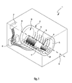
- Figure 1 is a perspective view of a rapid chilling apparatus for beverages according to the present invention;
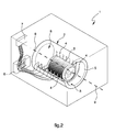
- Figure 2 is a view similar to the one appearing in Figure 1;
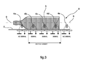
- Figure 3 is a side elevational, cross-sectional view of the rapid chilling apparatus according to the present invention, showing the receptacle and the electrodes in greater detail;
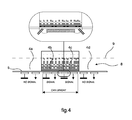
- Figure 4 is a view similar to the one appearing in Figure 3;
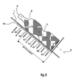
- Figure 5 is a side elevational, cross-sectional view of the rapid chilling apparatus according to a further embodiment of the present invention, showing the receptacle and the electrodes in greater detail;
- Figure 6 is a view similar to the one appearing in Figure 5.
- With reference to the above-cited Figures, the rapid chilling apparatus for beverages according to the present invention - as indicated generally at 1 in said Figures - comprises a
receptacle 2 adapted to accommodatebeverage containers 3 of differing length, such as bottles, cans and carton-like beverage packages, as well as cooling means adapted to cool down saidreceptacle 2. - The receptacle itself comprises a plurality of
electrodes 4 associated to aninner surface 5 of thereceptacle 2 and arranged in succession one after the other alongsuch surface 5. - The
inner surface 5 is in turn adapted to support acontainer 3 in such manner that theelectrodes 4 turn out as being distributed around thecontainer 3 along the whole length of the same container. - The
electrodes 4 are connected to circuit means 6 adapted to detect and measure the capacitance value on eachelectrode 4 as this is generated by the presence of acontainer 3 of a conductive material in proximity of thesame electrode 4, so as to determine the actual length of the container introduced in the receptacle, or - in the case of acontainer 3 of a non-conductive material - as generated by the presence, inside the container, of beverage liquid in proximity of thesame electrode 4, so as to determine the actual length of thecontainer 3 being wetted by the beverage liquid contained thereinside - In the case of a
container 3 of a non-conductive material, it is in fact the beverage liquid being in contact with the inner wall of the container that determines the capacitance value detected and measured on theelectrode 4, in the proximity of which such liquid is present. - The circuit means are further adapted to compare these detected capacitance values with pre-defined values in order to discriminate between containers of a conductive and a non-conductive material.
- Control means 7 are connected to the circuit means 6 to automatically operate the cooling means for a period of time, the duration of which is made dependant on the so determined length of the
container 3 introduced in thereceptacle 2, as well as on the material which the container is made of. - The
receptacle 2 is comprised of a body provided with acavity 8 that extends along anaxial direction 9 and is adapted to accommodate abeverage container 3. In particular, thereceptacle 2 is sized so as to be able to accommodate a bottle, a can or a beverage carton of different sizes, such as for instance a 0.25-litre, 0.33-litre, 0.5-litre, 0.75-litre, 1-litre and 1.5-litre bottle or can. - The
electrodes 4 are provided so as to lie on at least a portion of theinner surface 5 that defines thecavity 8 of thereceptacle 2, and are arranged in succession one after the other along such portion in a direction that is parallel to theaxial direction 9 of thecavity 8. - Preferably, the portion of
inner surface 5 of thecavity 8, on which theelectrodes 4 are arranged, is concave. - Furthermore, each
electrode 4 is preferably provided in the form of a thin plate of an electrically conductive material, which is bent so as to form an annular member adapted to be associated to the concave portion of theinner surface 5 of thereceptacle 2. - The concave shape of at least a portion of the
inner surface 5 of thecavity 8 of thereceptacle 2, and the corresponding annular conformation of theelectrodes 4, practically ensure that there is just a minimum distance separating the side wall of the container from theelectrodes 4 in view of ensuring a greater detection accuracy and sensitivity. - Preferably, the
receptacle 2 comprises a cylindrical hollow body. - It will be readily appreciated that the
receptacle 2 may anyway be provided in a number of different shapes and, in particular, it may have an elliptic, square or even polygonal cross-section and eachelectrode 4 can be provided in the form of a flat conductive element. - The
electrodes 4 may be associated to thereceptacle 2 in a manner as to cover, i.e. lie on theinner surface 5 of the latter; in this case, they are in turn covered with a thin isolating layer adapted to prevent theelectrodes 4 from being able to come into contact with water, moisture and liquids in general, which would of course affect the accuracy of the capacitance measurements made on the same electrodes. - In an alternative embodiment of the present invention, the
electrodes 4 are integrated or embedded within the thickness of the wall of the receptacle, so as to turn out as being positioned in proximity of theinner surface 5 of thereceptacle 2, below this surface. Such arrangement ensures that theelectrodes 4 are effectively insulated, while at the same time keeping the detection sensitivity on thesame electrodes 4 at an adequately high level. - The
electrodes 4 are associated to theinner surface 5 of thereceptacle 2 and arranged in succession one after the other along a direction that is parallel to theaxial direction 9 of thecavity 8 of thereceptacle 2. - In practice, when the
container 3 is placed in position inside thereceptacle 2 on theinner surface 5 thereof, theelectrodes 4 turn out as being distributed around the side wall of the same container over the entire length thereof, as this is best shown in Figures 1 and 2. - When it is placed in position for chilling, the
container 3 turns therefore out as resting onto theinner surface 5 of thereceptacle 2, with theelectrodes 4 lying quite close to thesame container 3, as solely separated from the side wall of the latter by the thin insulating layer therebetween. - The
electrodes 4 are spaced from each other along theinner surface 5 in theaxial direction 9 of thecavity 8 and, preferably, the distance between theelectrodes 4 is appropriately selected so as to ensure that both the position and the number of theelectrodes 4 can be correlated with the typical lengths of the bottles and cans and beverage cartons that are commonly to be found on the market, which usually contain standard beverage volumes, such as 0.25, 0.33, 0.5, 0.75, 1.0 and 1.5 litres. - Preferably, for an effective contact to be ensured between the
container 3 and theinner surface 5 of thereceptacle 2 and, as a result, for a minimum distance to be ensured between theelectrodes 4 and the side wall of thecontainer 3, thereceptacle 2 is arranged in an inclined position, i.e. is given a certain inclination relative to the vertical direction; in other words, theaxial direction 9, in which thecavity 8 extends, forms an angle with the vertical. - However, the
inner surface 5 supporting thecontainer 3 may be arranged and oriented both horizontally and vertically - The
electrodes 4 are connected to circuit means 6 that are adapted to detect and measure the capacitance value on theelectrodes 4 as this is brought about, i.e. generated by the conductive material, which thecontainer 3 being introduced in thereceptacle 2 is made of, or - in the case of a container made of a non-conductive material - by the beverage liquid wetting the inner wall of such container introduced in thereceptacle 2 for rapid cooling. - Such circuit means may for instance include an oscillatory circuit or a voltage divider, although - as those skilled in the art will readily be capable of appreciating - use can be made in this connection of other types of circuits that are generally known as such in the art.
- In a first embodiment of the present invention, the circuit means 6 are adapted to detect and measure the capacitance value on each
single electrode 4. - In a second embodiment of the present invention, the circuit means 6 are arranged so as to activate a
single electrode 4 at a time, while grounding the remaining ones or the remaining ones being connected to a reference potential or not being connected at all; in this way, they eventually activate all electrodes in a sequence, as this is best shown schematically in Figures 1 and 2. Then, the circuit means measure the capacitance value between the measurement electrode being activated each time and the other electrodes that are on the contrary grounded. In this way, a capacitance value on eachelectrode 4 is obtained.
In a third embodiment of the present invention there is provided a plurality of electrode pairs, of which one electrode is the measurement electrode and the other electrode is the grounded one. Then, the circuit means 6 measure the value of and the variation in capacitance between each pair of electrodes. - When the
receptacle 2 is empty, i.e. no container has been placed there for rapid cooling, the capacitance value measured on eachelectrode 4 is due to only air being the actual dielectric material. - In the case that a
beverage container 3 made of a non-conductive material, such as a glass or plastic bottle, or a carton-like beverage package of some kind, is introduced in thecavity 8 of thereceptacle 2, the capacitance value that is detected on theelectrodes 4 lying close to the side wall of the container changes in accordance with, i.e. depending on beverage liquid being or not being present in proximity of each such electrode. - As a matter of fact, the beverage liquid has a higher electric conductivity than air and even glass, plastic or cardboard, i.e. the non-conductive materials, which beverage containers currently available on the market are commonly made of.
- A number of experimental tests carried out in this connection have demonstrated that the sole presence of a container of a non-conductive material in an empty state thereof, i.e. not containing any liquid, inside the
receptacle 2, does not bring about any significant variation in the capacitance value measured on the electrodes as compared with the value measured on the same electrodes when nocontainer 3 is present in saidreceptacle 2. - In practice, the capacitance value being detected on the electrodes when a
container 3 of non-conductive material is placed in its empty state, i.e. without any liquid being contained therein, on theinner surface 5 of thereceptacle 2, is substantially equal to the capacitance value measured on thesame electrodes 4 when thereceptacle 2 itself is empty, i.e. no container is placed therein, so that said capacitance value is solely due to air acting as the actual dielectric. - On the other hand, when a
container 3 of a non-conductive material, but containing liquid is placed upon theinner surface 5 of thereceptacle 2, the electrodes that lie close to the side wall of thecontainer 3 being wetted or covered internally by the amount of beverage liquid contained therein, i.e. close to the side wall of thecontainer 3, the inner surface of which is in contact of the beverage liquid contained in the same container, deliver a capacitance value that is higher than the one that can be detected and measured on theelectrodes 4 facing portions of the side wall of thecontainer 3 that are on the contrary not wetted by any beverage liquid. - As described hereinbefore, and also based on what has been found experimentally, the capacitance value measured on the
electrodes 4 lying in the zone in which theinner surface 5 is in contact with the portion of side wall of thecontainer 3 that is not wetted by the beverage liquid contained therein, turns out as being substantially equal or quite similar to the value that is typically detected when solely air is present as a dielectric in thereceptacle 2, i.e. when such receptacle is empty. - The capacitance value measured on each
electrode 4 is greater in the situation in which the side wall of thecontainer 3 being wetted by the beverage liquid is in contact with the whole area of theinner surface 5 of thecavity 8 where anelectrode 4 lies. Conversely, in those situations in which the side wall of thecontainer 3 being wetted by the beverage liquid comes only partially in contact, or does not come into any contact at all, with the area of theinner surface 5 lying above anelectrode 4, the capacitance value detected on such electrode will be considerably lower and substantially comparable to the one brought about by only air being the actual dielectric in the receptacle, i.e. when the latter is empty, or by the same electrode lying in a zone in which theinner surface 5 of thecavity 8 is in contact with the side wall of thecontainer 3, but such side wall of thecontainer 3 is not wetted by any beverage liquid. - Low capacitance values may also indicate those
electrodes 4 that come to lie close to narrower or recessed portions of thecontainer 3, or tapering portions that do not come into contact with theinner surface 5 of thecavity 8, as these may in particular be quite frequently found in bottles currently available on the market. - The control means 7 are adapted to compare the capacitance values measured on each
electrode 4 with a first pre-determined threshold capacitance value representing a length reference level, i.e. a level indicative of length, which is used to discriminate whether the electrode is delivering a valid length signal for thecontainer 3 or it does not deliver any length signal at all. - Experimental tests have shown that an adequate value for the above-cited first threshold capacitance value is represented by the capacitance value due to only air being present in the
receptacle 2, i.e. due to such receptacle being empty, as increased by a quantity determined as a result of a number of tests. This quantity enables the capacitance values that are certainly and definitely indicative of the presence of beverage liquid in proximity of theelectrode 4 on which such value has been measured, to be discriminated from the capacitance values that are representative of situations in which beverage liquid is not present in proximity of theelectrode 4 owing to the side wall of thecontainer 3 not being wetted by, or not being in contact with the beverage liquid, or owing to the side wall of the container 3 - although wetted by or in contact with the beverage liquid contained therein - is spaced away from theelectrode 4 or comes to only partially lie above said electrode due to the particular shape of thecontainer 3. - In practice, the
electrode 4, whose capacitance value - as measured by said circuit means 6 - is in excess of said first threshold capacitance value, delivers a valid length signal for thecontainer 3, thereby indicating that the side wall of thecontainer 3 wetted by the beverage liquid is in contact with and occupies the area ofinner surface 5 of thecavity 8 in which that givenelectrode 4 is residing. - The control means 7 process and weigh the signals delivered by each
electrode 4 and, then, select - with reference to either ways of theaxial direction 9 of the cavity 8 - the first electrode and the last electrode that deliver a valid container length signal, the distance between theseelectrodes 4 representing the actual length of thecontainer 3. - In other words, among all those
electrodes 4 that deliver a valid length signal, the control means 7 select the two electrodes that lie farthest away from each other along theaxial direction 9 of thecavity 8, wherein such distance between such two electrodes is assumed to be the length of the container. - The control means 7 are of course duly set as to be able to associate each
electrode 4 to a given reference position inside the cavity of the receptacle, as well as to determine the distances between allelectrodes 4 from each other, the distance between twoadjacent electrodes 4 being in fact known. - In the case that the capacitance value measured on each
electrode 4 does not exceed the above-cited first threshold capacitance value, and none of theelectrodes 4 therefore delivers a valid length signal, the control means consider thecavity 8 of thereceptacle 2 as being empty, i.e. not accommodating anycontainer 3, or thereceptacle 2 as accommodating an empty container of a non-conductive material therein, so that they will not activate the cooling means. - Introducing a
container 3 of a non-conductive material, and containing beverage liquid therein, in thereceptacle 2, and having such container resting upon theinner surface 5 thereof, is instrumental in changing - as this has been described hereinbefore - the capacitance value being measured on eachelectrode 4 or, possibly, on each pair of electrodes, depending on the particular embodiment implemented, in accordance with the length of thecontainer 3 wetted by the beverage liquid. - The capacitance value detected on each
electrode 4 may furthermore deliver information about the material, which the container is made of, as this shall be described in greater detail below. - As this is best shown in Figure 3, which illustrates a container of non-conductive material placed in the
receptacle 2, the circuit means 6 measure on each one of thecentral electrodes outermost electrodes - Referring again to Figure 3, the
electrode 4a can be noticed to face a portion of the side wall of thecontainer 3 that is wetted by, i.e. in contact with the liquid contained therein, wherein such liquid, however, does not lie in proximity of theelectrode 4a since - owing to the particular shape of the container 3 - the side wall of the latter is spaced away from and not in contact with theinner surface 5 of thereceptacle 2 on which theelectrode 4a is positioned. - These signals are not only indicative of the presence of a bottle in the receptacle of the chilling arrangement, and inform the control means 7 accordingly, but they also enable the length of the same bottle wetted by the beverage liquid to be worked out and determined.
- Referring once again to Figure 3, the control means select - among the three
central electrodes axial direction 9 of thecavity 8, i.e. theelectrode 4b and theelectrode 4d in this case. The distance between these electrodes is then assumed as being the length of thecontainer 3. - Usually, for instance, 1.5-litre bottles currently available on the market have substantially the same size and, in particular, the same length. The same applies also to other bottles, such as for instance 0.5-litre bottles. It is therefore possible for a detected length of the container introduced in the receptacle to be univocally associated to a volume of the contents thereof.
- Thus, the control means 7 derive the length of the bottle, associate such length to a corresponding volumetric content thereof, and then activate the cooling means so as to cause the bottle, and the content thereof, to undergo rapid chilling.
- Furthermore, the control means 7 are adapted to cut off the operation of the cooling means after a pre-determined period of time, whose length has been selected so as to prove adequate in enabling the bottle to be effectively cooled down depending on the thus detected length of the same bottle and, as a result, the volumetric contents thereof.
- In this connection, it can be readily appreciated that equal and same cooling means will need a correspondingly longer time to be able to cool down a 1.5-litre bottle than a 0.5-litre one.
Of course, the same considerations as set forth above equally apply to carton-like beverage packages or the like. - As far as the cooling means themselves are concerned, they may for instance comprise a dedicated evaporator, in the case that the rapid chilling apparatus is constituted by a self-standing, i.e. autonomous unit that integrally comprises its
own receptacle 2, circuit means 6, control means 7 and cooling means. Conversely, the rapid chilling apparatus may be integrated in a refrigerator, in which the receptacle thereof may for instance be cooled down by a flow of cooling air taken in from the evaporator area of the refrigerator. - Illustrated in Figure 5 is a further embodiment of the inventive chilling apparatus, in which the
cavity 8 of thereceptacle 2, as well as theinner surface 5 thereof, are arranged so as to extend with an inclined orientation relative to the horizontal direction, and in which the circuit means 6 measure the capacitance value on eachelectrode 4. In the example being discussed here, in which a container of a non-conductive material is illustrated as being introduced in thereceptacle 2, the circuit means 6 will therefore measure on each one of theelectrodes electrodes - Referring again to Figure 5, the
electrodes inner surface 5 of thereceptacle 2, on which theelectrodes - Again with reference to Figure 5, the control means select - among the
electrodes axial direction 9 of thecavity 8, i.e. theelectrode 4c and theelectrode 4h in this case. The distance between these electrodes is then assumed as being the length of thecontainer 3. - Referring now to Figure 6, which illustrates a
container 3 of a non-conductive material inserted in thereceptacle 6, on each one of theelectrodes electrodes - In Figure 6, the
electrodes inner surface 5 of thecavity 8, is not wetted by, i.e. not in contact with the beverage liquid contained in said container. Therefore, since the liquid does not lie in proximity of saidelectrodes - Referring again to Figure 6, the control means select - among the
electrodes axial direction 9 of thecavity 8, i.e. theelectrode 4e and theelectrode 4h in this case. The distance between these electrodes is then assumed as being the length of thecontainer 3. - As it clearly appears from the example illustrated in Figure 6, in the case of
containers 3 that are made of a non-conductive material, the apparatus according to the present invention is capable of operating the cooling means for a length of time that depends on the actual length of thecontainer 3 as determined by the residual liquid content thereof, i.e. by the actual amount of beverage still held in the same container. - Again in the case of
containers 3 made of a non-conductive material, the control means 7 are adapted to compare the capacitance values measured on theelectrodes 4 delivering a valid length signal with a value that is representative of sold ice forming inside thecontainer 3. When the beverage in the container freezes down to solid ice, the capacitance value measured on the sensors exceeds the first threshold capacitance value, but is lower as an absolute value than the value that is detected in the condition in which the beverage in the container is in the liquid state thereof. The control means 7 are therefore adapted to switch off cooling operation as soon as they sense that the liquid beverage inside thecontainer 3 has undergone a phase transition to solid ice. - Further, It has been found that, in the case of
containers 3 made of a non-conductive material, the capacitance value measured on theelectrodes 4 delivering a valid length signal varies in accordance with the amount of liquid still present inside thecontainer 3. When the container is totally filled, the capacitance value detected on the electrodes is greater than the value that is measured when the same container is just half-filled, this being attributable to the fact that the differing liquid layer that comes to lie above the electrodes in these two cases, is most obviously effective in determining different conditions of electric conductivity. - The control means are adapted to compare the capacitance values measured on the electrodes delivering a valid length signal with corresponding reference values, so as to determine the amount of beverage liquid contained in the container, whose length has been determined as explained above. This can be applied not only to the embodiment illustrated in Figure 3, in which the
receptacle 2 and theinner surface 5, along with the containers inserted therein, lie in a horizontal position, but also to the embodiments illustrated in Figures 5 and 6. - In the case of a container made of a conductive material, such as for instance an aluminium can, the capacitance value detected by the circuit means 6 on each
electrode 4 is solely determined by the presence of the side wall of the container in proximity of the same electrode, regardless of the container itself holding liquid or not. - Each
electrode 4 lying close to the side wall of the container made of electrically conductive material forms with the latter a kind of capacitor, owing exactly to the high electrical conductivity property of the material which the container is made of. - Those
electrodes 4 that are positioned in the zone where the side wall of thecontainer 3 is in contact with theinner surface 5, i.e. the electrodes that lie under, i.e. facing the zone where the side wall of the container is in contact with said inner surface, deliver a high capacitance value. Thoseelectrodes 4 that on the contrary lie in a zone of theinner surface 5, in which the latter is not in contact with the side wall of thecontainer 3, deliver a capacitance value that is determined by air acting as the dielectric and, as a result, is extremely low, as described in the previously considered case of containers made of non-conductive material. - The capacitance value measured on each
electrode 4 is greater in the situation in which the side wall of thecontainer 3 is in contact with the whole area of theinner surface 5 of thecavity 8 where anelectrode 4 lies. Conversely, in those situations in which the side wall of thecontainer 3 only partially in contact, or does not come into any contact at all, with the area of theinner surface 5 lying above anelectrode 4, the capacitance value detected on such electrode will be considerably lower and substantially comparable to the one brought about by only air being the actual dielectric in the receptacle. - Low capacitance values may also indicate those
electrodes 4 that come to lie close to narrower or recessed portions of thecontainer 3, or tapering portions that do not come into contact with theinner surface 5 of thecavity 8. - The capacitance value measured on the
electrodes 4 that are located in the zone in which theinner surface 5 is in contact with the container of conductive material placed in the receptacle, is not only clearly greater than the first reference threshold value, but also significantly greater than the capacitance value detected on each electrode in the case of a container made of a non-conductive material. - The control means 7 are adapted to consider a second threshold capacitance value that represents a kind of material detection level, beyond which the container in the receptacle may be assumed to be made of metal and, as a result, to be for instance a can.
- Owing to them being able to rely on a greater heat conductivity than glass or plastic bottles, cans and containers made of electrically conductive material in general allow for a much quicker cooling effect for a same volumetric content. Since 0.5-litre bottles have a same length as 0.5-litre cans, it clearly appears that being able to discriminate between these two types of containers is of great practical importance, in view of optimizing the cooling time by activating the cooling means for different lengths of time depending on the material which the container is made of.
- As best shown in Figure 4, on each one of the
central electrodes inner surface 5, the circuit means measure a capacitance value that is greater than the first threshold value and greater than the second threshold value. Each one ofsuch electrodes outermost electrodes - The length of a can is determined in the same way as the length of a bottle.
- Cans have standard sizes in accordance with the volumetric content thereof. In other words, all 0.33-litre cans have the same length, and the same applies also to all 0.25-litre and 0.5-litre cans, respectively. It is therefore possible for the detected length of a can to be univocally associated to a volume of the contents thereof.
- Based on the values measured by the circuit means 6, the control means 7 derive the length of the container, establish that the container itself is made of metal and, therefore, is a can, associate such length to a corresponding volumetric content, and then activate the cooling means in view of having the can rapidly chilled along with the contents thereof. In other words, said cooling means carry out a cooling cycle that depends on the length of the container and, therefore, the volumetric content thereof, as well as the material - i.e. metal in the case of a can - which the container is made of.
Claims (16)
- Rapid chilling apparatus for beverages comprising a receptacle (2) adapted to accommodate beverage containers (3) of differing length, and cooling means adapted to cool down said receptacle (2), characterized in that said receptacle (2) comprises a plurality of electrodes (4) arranged in succession one after the other along an inner surface (5) of said receptacle (2), said inner surface (5) being adapted to support a container (3) in such manner that said electrodes (4) turn out as being distributed along the whole length of the container (3), said electrodes (4) being connected to circuit means (6) adapted to detect and measure the capacitance value on each electrode (4) as brought about by the presence of a container (3) made of a conductive material in proximity of the same electrode (4) so as to determine the actual length of the container (3), or, in the case of a container (3) made of a non-conductive material, said capacitance value as brought about by the presence, inside the container (3), of beverage liquid in proximity of the same electrode (4), so as to determine the actual length of the container (3) being wetted by the beverage liquid contained thereinside, control means (7) being provided to operate said cooling means in response to the capacitance values detected by said circuit means (6) for a period of time, the duration of which is made dependant on the so determined length of the container (3).
- Apparatus according to claim 1, wherein said control means (7) are adapted to compare said capacitance values with a pre-defined value in order to determine whether the container (3) is made of a conductive material, the duration of said operating time of the cooling means depending on the material which the container (3) is made of.
- Apparatus according to claim 1, wherein the control means (7), in the case of containers made of a non-conductive material, are adapted to compare the capacitance values measured on the electrodes (4) with corresponding reference values so as to determine the amount of beverage liquid still present inside the container.
- Apparatus according to any one of claims 1-3, wherein said electrodes (4) are associated to an inner surface (5) of the receptacle (2) and arranged in succession one after the other along an axial direction (9), said inner surface (5) being adapted to support said container (3).
- Apparatus according to claim 4, wherein said electrodes (4) are applied onto said inner surface (5) of the receptacle (2) and a protective layer is applied to cover said electrodes (4).
- Apparatus according to claim 4, wherein said electrodes (4) are integrated or embedded within the thickness of the wall of the receptacle, so as to turn out as being positioned in proximity of the inner surface (5) of the receptacle (2).
- Apparatus according to claim 1, wherein said circuit means (6) comprise an oscillatory circuit.
- Apparatus according to claim 1, wherein said control means (7) are adapted to compare the capacitance values measured on each electrode (4) with a first pre-determined threshold capacitance value representing a length reference level, which is used to discriminate whether the electrode is delivering a valid length signal for the container (3) or does not deliver any length signal at all.
- Apparatus according to claim 8, wherein the control means (7) are adapted to infer that no container (3) is present in the receptacle (2) and, furthermore, in the case of a container made of a non-conductive material, that the container introduced in the receptacle (2) is empty and, as a result, do not activate the cooling means, when the capacitance value measured on each electrode (4) does not exceed the first threshold capacitance value and, therefore, none of the electrodes (4) delivers a valid length signal.
- Apparatus according to claim 8, wherein the electrode (4), whose capacitance value is in excess of said first threshold capacitance value, delivers a valid length signal for the container (3) by indicating that lying in proximity of said electrode (4) there is the side wall of a container of a conductive material, and, in case of a container (3) made of a non-conductive material, by indicating that lying in proximity of said electrode (4) there is the side wall of the container being wetted by the beverage liquid contained therein, and wherein the electrode (4), whose capacitance value is lower than said first threshold capacitance value, does not deliver any valid length signal for the container (3) by indicating that the side wall of the container (3) is spaced away from the electrode (4) and, furthermore, in the case of a container made of a non-conductive material, that the side wall of the container (3), although lying in proximity of the electrode (4), is not wetted by the beverage liquid inside the container.
- Apparatus according to any of the preceding claims, wherein the control means (7) are adapted to select, among all electrodes (4) delivering a valid length signal, the two electrodes that lie farthest away from each other along said axial direction (9), said control means (7) being adapted to assume such distance between these two electrodes as being the length of the container.
- Apparatus according to any of the preceding claims, wherein the control means (7) are adapted to compare the capacitance value measured on each electrode (4) with a second threshold capacitance value, which is higher than the first threshold capacitance value and represents a reference material-identification level, beyond which the container is assumed to be made of a conductive material.
- Apparatus according to any of the preceding claims, wherein the control means (7), on the basis of the values measured on the electrodes (4), are adapted to derive the length of the container, associate such length to a corresponding volumetric content of the same container (3), establish whether the container itself is made of a conductive material and then activate the cooling means to operate in accordance with the so detected volumetric content and material of the container.
- Apparatus according to any of the preceding claims, wherein the control means (7), in the case of containers made of a non-conductive material, are adapted to compare the capacitance values measured on the electrodes (4) delivering a valid length signal with a value that is representative of solid ice forming inside the container (3), said control means (7) being thus adapted to switch off cooling as soon as they sense that the liquid beverage inside the container (3) has undergone a phase transition to solid ice.
- Method for controlling a rapid chilling apparatus for beverages comprising a receptacle (2) adapted to accommodate beverage containers (3) of differing length, of the bottle, can, carton or similar type, and cooling means adapted to cool down said receptacle (2), characterized in that it comprises the steps of:- providing a plurality of electrodes (4) arranged in succession one after the other along an inner surface (5) of said receptacle (2), said inner surface (5) being adapted to support a container (3) so that said electrodes (4) turn out as being distributed over the whole length of the container (3);- detecting and measuring the capacitance value on each electrode (4) as brought about by the presence in the receptacle (2) of a container (3) made of a conductive material in proximity of the same electrode (4), so as to determine the length of the said container (3), or- in the case of a container made of a non-conductive material being introduced in said receptacle (2), as brought about by the presence of beverage liquid in proximity of the same electrode (4), so as to determine the actual length of the container (3) being wetted by the beverage liquid contained thereinside;- operating cooling means, in response to the detected capacitance values, for a period of time whose duration depends on the so determined length of the container.
- Rapid chilling method for beverages according to claim 18, further comprising the steps of:- comparing said capacitance values with a pre-established value to determine whether the container is of electrically conductive material,- operating said cooling means in response to the detected capacitance values for a period of time, whose duration depends on the material which the container is made of.
Priority Applications (10)
| Application Number | Priority Date | Filing Date | Title |
|---|---|---|---|
| EP06101054.2A EP1821053B1 (en) | 2006-01-31 | 2006-01-31 | Rapid chilling apparatus for beverages and method for controlling the same |
| PL06101054T PL1821053T3 (en) | 2006-01-31 | 2006-01-31 | Rapid chilling apparatus for beverages and method for controlling the same |
| US12/093,007 US8453472B2 (en) | 2006-01-31 | 2007-01-29 | Rapid chilling apparatus for beverages and method for controlling the same |
| KR1020087014734A KR101315524B1 (en) | 2006-01-31 | 2007-01-29 | Rapid chilling apparatus for beverages and method for controlling the same |
| AU2007211538A AU2007211538B2 (en) | 2006-01-31 | 2007-01-29 | Rapid chilling apparatus for beverages and method for controlling the same |
| CN200780001702A CN100582620C (en) | 2006-01-31 | 2007-01-29 | Quick freezing device for beverage and method for controlling the same |
| JP2008551802A JP4913831B2 (en) | 2006-01-31 | 2007-01-29 | Rapid cooling apparatus for beverage and control method thereof |
| BRPI0706295A BRPI0706295B1 (en) | 2006-01-31 | 2007-01-29 | fast drink cooler, and method for controlling a fast drink cooler |
| PCT/EP2007/050832 WO2007088153A1 (en) | 2006-01-31 | 2007-01-29 | Rapid chilling apparatus for beverages and method for controlling the same |
| RU2008135347/21A RU2410611C2 (en) | 2006-01-31 | 2007-01-29 | Device for quick cooling of drinks and method of handlingthis device |
Applications Claiming Priority (1)
| Application Number | Priority Date | Filing Date | Title |
|---|---|---|---|
| EP06101054.2A EP1821053B1 (en) | 2006-01-31 | 2006-01-31 | Rapid chilling apparatus for beverages and method for controlling the same |
Publications (2)
| Publication Number | Publication Date |
|---|---|
| EP1821053A1 true EP1821053A1 (en) | 2007-08-22 |
| EP1821053B1 EP1821053B1 (en) | 2015-11-04 |
Family
ID=36602634
Family Applications (1)
| Application Number | Title | Priority Date | Filing Date |
|---|---|---|---|
| EP06101054.2A Expired - Lifetime EP1821053B1 (en) | 2006-01-31 | 2006-01-31 | Rapid chilling apparatus for beverages and method for controlling the same |
Country Status (10)
| Country | Link |
|---|---|
| US (1) | US8453472B2 (en) |
| EP (1) | EP1821053B1 (en) |
| JP (1) | JP4913831B2 (en) |
| KR (1) | KR101315524B1 (en) |
| CN (1) | CN100582620C (en) |
| AU (1) | AU2007211538B2 (en) |
| BR (1) | BRPI0706295B1 (en) |
| PL (1) | PL1821053T3 (en) |
| RU (1) | RU2410611C2 (en) |
| WO (1) | WO2007088153A1 (en) |
Cited By (8)
| Publication number | Priority date | Publication date | Assignee | Title |
|---|---|---|---|---|
| EP2103891A1 (en) | 2008-03-17 | 2009-09-23 | Electrolux Home Products Corporation N.V. | Method and appliance for refrigerating beverages |
| ITMC20080217A1 (en) * | 2008-12-05 | 2010-06-06 | Luigi Travaglini | FAN-ASSISTED THERMAL ACCUMULATOR ACTING TO REFRIGERATE QUICKLY |
| WO2010149402A1 (en) | 2009-06-25 | 2010-12-29 | Cambridge Design Research Llp | Dispensing apparatus and methods |
| EP2525171A4 (en) * | 2010-03-09 | 2014-02-19 | Panasonic Corp | FRIDGE |
| GB2530327A (en) * | 2014-09-22 | 2016-03-23 | 42 Technology Ltd | Heat transfer apparatus |
| US11640741B2 (en) | 2019-03-25 | 2023-05-02 | Pepsico, Inc. | Beverage container dispenser and method for dispensing beverage containers |
| US11910815B2 (en) | 2019-12-02 | 2024-02-27 | Pepsico, Inc. | Device and method for nucleation of a supercooled beverage |
| US12059082B2 (en) * | 2019-04-05 | 2024-08-13 | Pepsico, Inc. | Cooler for beverage containers |
Families Citing this family (9)
| Publication number | Priority date | Publication date | Assignee | Title |
|---|---|---|---|---|
| JP5033743B2 (en) * | 2008-09-18 | 2012-09-26 | 株式会社テックスイージー | Container temperature control device |
| EP2593730B1 (en) * | 2010-07-13 | 2018-12-19 | LG Electronics Inc. | Cooling apparatus and refrigerator having the same |
| US9845988B2 (en) * | 2014-02-18 | 2017-12-19 | Supercooler Technologies, Inc. | Rapid spinning liquid immersion beverage supercooler |
| JP6316017B2 (en) * | 2014-02-13 | 2018-04-25 | Nissha株式会社 | Product detection device |
| CN108020016B (en) * | 2016-11-03 | 2019-12-10 | 比亚迪股份有限公司 | Control device, method, system and automobile for vehicle-mounted refrigerator |
| CN109612200B (en) * | 2018-12-07 | 2021-02-19 | 长虹美菱股份有限公司 | A Quick Chilling Method for Beer and Beverages |
| DE112020002300T5 (en) * | 2019-05-09 | 2022-02-17 | Rohm Co. Ltd. | refrigerator |
| NL2024209B1 (en) * | 2019-11-11 | 2021-07-28 | Heineken Supply Chain Bv | Cooling system for a liquid dispensing assembly |
| WO2024251241A1 (en) * | 2023-06-08 | 2024-12-12 | 中山宝丽图电子技术有限公司 | Consumable bearing carrier and printer |
Citations (4)
| Publication number | Priority date | Publication date | Assignee | Title |
|---|---|---|---|---|
| US4358932A (en) * | 1981-09-03 | 1982-11-16 | General Electric Company | Control system for refrigerator with through-the-door quick-chilling service |
| US5168714A (en) * | 1990-08-16 | 1992-12-08 | The Coca-Cola Company | Assembly, especially for a beverage-vending machine, with a container for the storage, cooling and carbonating of water |
| JP2002081848A (en) * | 2000-09-06 | 2002-03-22 | Toshiba Corp | Food control storage |
| JP2002128196A (en) * | 2000-10-19 | 2002-05-09 | Takane Denki Kk | Beverage cooling server |
Family Cites Families (23)
| Publication number | Priority date | Publication date | Assignee | Title |
|---|---|---|---|---|
| JPS6014393B2 (en) * | 1977-03-01 | 1985-04-12 | 松下冷機株式会社 | Vending machine vending control device |
| US4368622A (en) * | 1981-05-14 | 1983-01-18 | General Electric Company | Refrigerator with through-the-door quick-chilling service |
| SU1508973A3 (en) * | 1986-04-25 | 1989-09-15 | Дзе Кока-Кола Компани (Фирма) | Refrigeration apparatus for cooling containers and foodstuffs |
| JPH0226000A (en) | 1988-07-15 | 1990-01-29 | Fuji Electric Co Ltd | Commodity heating control system for canned commodity vending machine |
| JPH087826B2 (en) | 1990-11-05 | 1996-01-29 | 松下冷機株式会社 | Vending machine with induction heating device |
| JP4124816B2 (en) | 1992-03-19 | 2008-07-23 | ヘンリー エム.ジャクソン ファウンデーション フォー ザ アドバンスメント オブ ミリタリー メディスン | Broadly reactive opsonin antibodies that react with normal staphylococcal antigens |
| JPH0689388A (en) * | 1992-09-07 | 1994-03-29 | Sanyo Electric Co Ltd | Cup type automatic vending machine |
| JPH0791797A (en) | 1993-09-24 | 1995-04-04 | Morinaga Eng Kk | Beverage cooling system in containers |
| US5406843A (en) * | 1993-10-27 | 1995-04-18 | Kdi Corporation, Inc. | Digital liquid level sensing apparatus |
| JPH0927071A (en) * | 1995-07-11 | 1997-01-28 | Sanyo Electric Co Ltd | Canned drink induction heating device |
| JPH09305854A (en) * | 1996-05-09 | 1997-11-28 | Fuji Electric Co Ltd | vending machine |
| JPH10143742A (en) * | 1996-11-07 | 1998-05-29 | Japan Organo Co Ltd | Method for detecting liquid shortage of automatic vending machine and device therefor |
| JPH10188114A (en) * | 1996-12-25 | 1998-07-21 | Fuji Electric Co Ltd | Vending machine control device |
| CN2288400Y (en) * | 1997-03-25 | 1998-08-19 | 青岛制冷技术研究所 | Quick-freezing refrigerator |
| JP2001174122A (en) * | 1999-12-22 | 2001-06-29 | Sanyo Electric Co Ltd | Heating cooling apparatus |
| DE10008093B4 (en) * | 2000-02-22 | 2007-07-05 | Ifm Electronic Gmbh | Capacitive level gauge |
| JP2001330357A (en) * | 2000-05-19 | 2001-11-30 | Fujitsu General Ltd | Wine storage equipment |
| US6474093B1 (en) * | 2000-10-23 | 2002-11-05 | Cosmo Tech Development, Inc. | Expanding barrel system for cooling beverages |
| JP4003036B2 (en) * | 2001-08-23 | 2007-11-07 | 富士ゼロックス株式会社 | Vending machines and containers used in vending machines |
| JP2003332037A (en) * | 2002-05-16 | 2003-11-21 | Mitsubishi Electric Corp | High frequency dielectric heating device and refrigeration device |
| CN2685781Y (en) * | 2004-02-16 | 2005-03-16 | 海信(北京)电器有限公司 | Automatic quick-freezing refrigerator |
| US7240690B2 (en) * | 2004-12-01 | 2007-07-10 | Torrent Trading Ltd. | Valve assembly with overfill protection device and capacitive liquid level gauge |
| US7347055B2 (en) * | 2005-11-07 | 2008-03-25 | Coors Global Properties, Inc. | Rapid chilling apparatus and method for a beverage-filled container |
-
2006
- 2006-01-31 EP EP06101054.2A patent/EP1821053B1/en not_active Expired - Lifetime
- 2006-01-31 PL PL06101054T patent/PL1821053T3/en unknown
-
2007
- 2007-01-29 RU RU2008135347/21A patent/RU2410611C2/en not_active IP Right Cessation
- 2007-01-29 AU AU2007211538A patent/AU2007211538B2/en not_active Ceased
- 2007-01-29 US US12/093,007 patent/US8453472B2/en not_active Expired - Fee Related
- 2007-01-29 CN CN200780001702A patent/CN100582620C/en not_active Expired - Fee Related
- 2007-01-29 BR BRPI0706295A patent/BRPI0706295B1/en not_active IP Right Cessation
- 2007-01-29 WO PCT/EP2007/050832 patent/WO2007088153A1/en not_active Ceased
- 2007-01-29 KR KR1020087014734A patent/KR101315524B1/en not_active Expired - Fee Related
- 2007-01-29 JP JP2008551802A patent/JP4913831B2/en not_active Expired - Fee Related
Patent Citations (4)
| Publication number | Priority date | Publication date | Assignee | Title |
|---|---|---|---|---|
| US4358932A (en) * | 1981-09-03 | 1982-11-16 | General Electric Company | Control system for refrigerator with through-the-door quick-chilling service |
| US5168714A (en) * | 1990-08-16 | 1992-12-08 | The Coca-Cola Company | Assembly, especially for a beverage-vending machine, with a container for the storage, cooling and carbonating of water |
| JP2002081848A (en) * | 2000-09-06 | 2002-03-22 | Toshiba Corp | Food control storage |
| JP2002128196A (en) * | 2000-10-19 | 2002-05-09 | Takane Denki Kk | Beverage cooling server |
Non-Patent Citations (2)
| Title |
|---|
| PATENT ABSTRACTS OF JAPAN vol. 2002, no. 07 3 July 2002 (2002-07-03) * |
| PATENT ABSTRACTS OF JAPAN vol. 2002, no. 09 4 September 2002 (2002-09-04) * |
Cited By (10)
| Publication number | Priority date | Publication date | Assignee | Title |
|---|---|---|---|---|
| EP2103891A1 (en) | 2008-03-17 | 2009-09-23 | Electrolux Home Products Corporation N.V. | Method and appliance for refrigerating beverages |
| ITMC20080217A1 (en) * | 2008-12-05 | 2010-06-06 | Luigi Travaglini | FAN-ASSISTED THERMAL ACCUMULATOR ACTING TO REFRIGERATE QUICKLY |
| WO2010149402A1 (en) | 2009-06-25 | 2010-12-29 | Cambridge Design Research Llp | Dispensing apparatus and methods |
| EP2525171A4 (en) * | 2010-03-09 | 2014-02-19 | Panasonic Corp | FRIDGE |
| GB2530327A (en) * | 2014-09-22 | 2016-03-23 | 42 Technology Ltd | Heat transfer apparatus |
| US11640741B2 (en) | 2019-03-25 | 2023-05-02 | Pepsico, Inc. | Beverage container dispenser and method for dispensing beverage containers |
| US11837059B2 (en) | 2019-03-25 | 2023-12-05 | Pepsico, Inc. | Beverage container dispenser and method for dispensing beverage containers |
| US12059082B2 (en) * | 2019-04-05 | 2024-08-13 | Pepsico, Inc. | Cooler for beverage containers |
| US11910815B2 (en) | 2019-12-02 | 2024-02-27 | Pepsico, Inc. | Device and method for nucleation of a supercooled beverage |
| US12295398B2 (en) | 2019-12-02 | 2025-05-13 | Pepsico, Inc. | Device and method for nucleation of a supercooled beverage using an ultrasonic transducer |
Also Published As
| Publication number | Publication date |
|---|---|
| CN101360963A (en) | 2009-02-04 |
| BRPI0706295B1 (en) | 2018-07-17 |
| BRPI0706295A2 (en) | 2011-03-22 |
| US8453472B2 (en) | 2013-06-04 |
| JP4913831B2 (en) | 2012-04-11 |
| CN100582620C (en) | 2010-01-20 |
| AU2007211538A1 (en) | 2007-08-09 |
| WO2007088153A1 (en) | 2007-08-09 |
| KR101315524B1 (en) | 2013-10-08 |
| RU2410611C2 (en) | 2011-01-27 |
| US20090139247A1 (en) | 2009-06-04 |
| KR20080091761A (en) | 2008-10-14 |
| EP1821053B1 (en) | 2015-11-04 |
| RU2008135347A (en) | 2010-03-10 |
| JP2009525449A (en) | 2009-07-09 |
| PL1821053T3 (en) | 2016-04-29 |
| AU2007211538B2 (en) | 2011-10-20 |
Similar Documents
| Publication | Publication Date | Title |
|---|---|---|
| AU2007211538B2 (en) | Rapid chilling apparatus for beverages and method for controlling the same | |
| CN107250692B (en) | Beverage cooling | |
| US20160355388A1 (en) | Auto Water Dispenser Cutoff | |
| RU2005120633A (en) | COOLING SYSTEM FOR DRINKING ALCOHOLIC BEVERAGES | |
| EP3610209B1 (en) | A cooling bath for cooling a liquid | |
| EP4058397B1 (en) | Beverage container cooling system for a beverage dispensing device | |
| US7828247B2 (en) | Automatic recycling ice detector | |
| US6311503B1 (en) | Methods and apparatus for detecting ice readiness | |
| MX2008009734A (en) | Rapid chilling apparatus for beverages and method for controlling the same | |
| US20160313045A1 (en) | Ice bin level sensor | |
| CN223453097U (en) | Water supply equipment | |
| US11920848B2 (en) | Sensor assembly for detecting ice level in a water jacket cooled ice storage chamber | |
| US20260110478A1 (en) | Ice level sensor for an ice bin in an ice dispenser system | |
| EP3760953B1 (en) | Apparatus and method for detecting a formation of ice in a household appliance | |
| GB2082743A (en) | An Electrode Assembly for an Ice-Bank Cooler | |
| AU2005200677B2 (en) | Food preserving systems | |
| HK1240646A1 (en) | Beverage cooling |
Legal Events
| Date | Code | Title | Description |
|---|---|---|---|
| PUAI | Public reference made under article 153(3) epc to a published international application that has entered the european phase |
Free format text: ORIGINAL CODE: 0009012 |
|
| 17P | Request for examination filed |
Effective date: 20070427 |
|
| AK | Designated contracting states |
Kind code of ref document: A1 Designated state(s): AT BE BG CH CY CZ DE DK EE ES FI FR GB GR HU IE IS IT LI LT LU LV MC NL PL PT RO SE SI SK TR |
|
| AX | Request for extension of the european patent |
Extension state: AL BA HR MK YU |
|
| AKX | Designation fees paid |
Designated state(s): AT BE BG CH CY CZ DE DK EE ES FI FR GB GR HU IE IS IT LI LT LU LV MC NL PL PT RO SE SI SK TR |
|
| RAP1 | Party data changed (applicant data changed or rights of an application transferred) |
Owner name: ELECTROLUX HOME PRODUCTS CORPORATION N.V. |
|
| RAP1 | Party data changed (applicant data changed or rights of an application transferred) |
Owner name: ELECTROLUX HOME PRODUCTS CORPORATION N.V. |
|
| REG | Reference to a national code |
Ref country code: DE Ref legal event code: R079 Ref document number: 602006047131 Country of ref document: DE Free format text: PREVIOUS MAIN CLASS: F25D0031000000 Ipc: G01B0007020000 |
|
| GRAP | Despatch of communication of intention to grant a patent |
Free format text: ORIGINAL CODE: EPIDOSNIGR1 |
|
| RIC1 | Information provided on ipc code assigned before grant |
Ipc: F25D 31/00 20060101ALI20150508BHEP Ipc: F25D 29/00 20060101ALI20150508BHEP Ipc: G01B 7/02 20060101AFI20150508BHEP |
|
| INTG | Intention to grant announced |
Effective date: 20150601 |
|
| GRAS | Grant fee paid |
Free format text: ORIGINAL CODE: EPIDOSNIGR3 |
|
| GRAA | (expected) grant |
Free format text: ORIGINAL CODE: 0009210 |
|
| AK | Designated contracting states |
Kind code of ref document: B1 Designated state(s): AT BE BG CH CY CZ DE DK EE ES FI FR GB GR HU IE IS IT LI LT LU LV MC NL PL PT RO SE SI SK TR |
|
| REG | Reference to a national code |
Ref country code: GB Ref legal event code: FG4D |
|
| REG | Reference to a national code |
Ref country code: CH Ref legal event code: EP |
|
| REG | Reference to a national code |
Ref country code: AT Ref legal event code: REF Ref document number: 759504 Country of ref document: AT Kind code of ref document: T Effective date: 20151115 |
|
| REG | Reference to a national code |
Ref country code: IE Ref legal event code: FG4D |
|
| REG | Reference to a national code |
Ref country code: DE Ref legal event code: R096 Ref document number: 602006047131 Country of ref document: DE |
|
| REG | Reference to a national code |
Ref country code: FR Ref legal event code: PLFP Year of fee payment: 11 |
|
| REG | Reference to a national code |
Ref country code: NL Ref legal event code: MP Effective date: 20151104 |
|
| REG | Reference to a national code |
Ref country code: LT Ref legal event code: MG4D |
|
| REG | Reference to a national code |
Ref country code: AT Ref legal event code: MK05 Ref document number: 759504 Country of ref document: AT Kind code of ref document: T Effective date: 20151104 |
|
| PG25 | Lapsed in a contracting state [announced via postgrant information from national office to epo] |
Ref country code: NL Free format text: LAPSE BECAUSE OF FAILURE TO SUBMIT A TRANSLATION OF THE DESCRIPTION OR TO PAY THE FEE WITHIN THE PRESCRIBED TIME-LIMIT Effective date: 20151104 Ref country code: LT Free format text: LAPSE BECAUSE OF FAILURE TO SUBMIT A TRANSLATION OF THE DESCRIPTION OR TO PAY THE FEE WITHIN THE PRESCRIBED TIME-LIMIT Effective date: 20151104 Ref country code: ES Free format text: LAPSE BECAUSE OF FAILURE TO SUBMIT A TRANSLATION OF THE DESCRIPTION OR TO PAY THE FEE WITHIN THE PRESCRIBED TIME-LIMIT Effective date: 20151104 Ref country code: IS Free format text: LAPSE BECAUSE OF FAILURE TO SUBMIT A TRANSLATION OF THE DESCRIPTION OR TO PAY THE FEE WITHIN THE PRESCRIBED TIME-LIMIT Effective date: 20160304 |
|
| PG25 | Lapsed in a contracting state [announced via postgrant information from national office to epo] |
Ref country code: SE Free format text: LAPSE BECAUSE OF FAILURE TO SUBMIT A TRANSLATION OF THE DESCRIPTION OR TO PAY THE FEE WITHIN THE PRESCRIBED TIME-LIMIT Effective date: 20151104 Ref country code: LV Free format text: LAPSE BECAUSE OF FAILURE TO SUBMIT A TRANSLATION OF THE DESCRIPTION OR TO PAY THE FEE WITHIN THE PRESCRIBED TIME-LIMIT Effective date: 20151104 Ref country code: FI Free format text: LAPSE BECAUSE OF FAILURE TO SUBMIT A TRANSLATION OF THE DESCRIPTION OR TO PAY THE FEE WITHIN THE PRESCRIBED TIME-LIMIT Effective date: 20151104 Ref country code: BE Free format text: LAPSE BECAUSE OF NON-PAYMENT OF DUE FEES Effective date: 20160131 Ref country code: PT Free format text: LAPSE BECAUSE OF FAILURE TO SUBMIT A TRANSLATION OF THE DESCRIPTION OR TO PAY THE FEE WITHIN THE PRESCRIBED TIME-LIMIT Effective date: 20160304 Ref country code: AT Free format text: LAPSE BECAUSE OF FAILURE TO SUBMIT A TRANSLATION OF THE DESCRIPTION OR TO PAY THE FEE WITHIN THE PRESCRIBED TIME-LIMIT Effective date: 20151104 Ref country code: GR Free format text: LAPSE BECAUSE OF FAILURE TO SUBMIT A TRANSLATION OF THE DESCRIPTION OR TO PAY THE FEE WITHIN THE PRESCRIBED TIME-LIMIT Effective date: 20160205 |
|
| PG25 | Lapsed in a contracting state [announced via postgrant information from national office to epo] |
Ref country code: CZ Free format text: LAPSE BECAUSE OF FAILURE TO SUBMIT A TRANSLATION OF THE DESCRIPTION OR TO PAY THE FEE WITHIN THE PRESCRIBED TIME-LIMIT Effective date: 20151104 |
|
| REG | Reference to a national code |
Ref country code: DE Ref legal event code: R097 Ref document number: 602006047131 Country of ref document: DE |
|
| PG25 | Lapsed in a contracting state [announced via postgrant information from national office to epo] |
Ref country code: RO Free format text: LAPSE BECAUSE OF FAILURE TO SUBMIT A TRANSLATION OF THE DESCRIPTION OR TO PAY THE FEE WITHIN THE PRESCRIBED TIME-LIMIT Effective date: 20151104 Ref country code: SK Free format text: LAPSE BECAUSE OF FAILURE TO SUBMIT A TRANSLATION OF THE DESCRIPTION OR TO PAY THE FEE WITHIN THE PRESCRIBED TIME-LIMIT Effective date: 20151104 Ref country code: LU Free format text: LAPSE BECAUSE OF FAILURE TO SUBMIT A TRANSLATION OF THE DESCRIPTION OR TO PAY THE FEE WITHIN THE PRESCRIBED TIME-LIMIT Effective date: 20160131 Ref country code: EE Free format text: LAPSE BECAUSE OF FAILURE TO SUBMIT A TRANSLATION OF THE DESCRIPTION OR TO PAY THE FEE WITHIN THE PRESCRIBED TIME-LIMIT Effective date: 20151104 Ref country code: DK Free format text: LAPSE BECAUSE OF FAILURE TO SUBMIT A TRANSLATION OF THE DESCRIPTION OR TO PAY THE FEE WITHIN THE PRESCRIBED TIME-LIMIT Effective date: 20151104 |
|
| REG | Reference to a national code |
Ref country code: CH Ref legal event code: PL |
|
| PLBE | No opposition filed within time limit |
Free format text: ORIGINAL CODE: 0009261 |
|
| STAA | Information on the status of an ep patent application or granted ep patent |
Free format text: STATUS: NO OPPOSITION FILED WITHIN TIME LIMIT |
|
| PG25 | Lapsed in a contracting state [announced via postgrant information from national office to epo] |
Ref country code: MC Free format text: LAPSE BECAUSE OF FAILURE TO SUBMIT A TRANSLATION OF THE DESCRIPTION OR TO PAY THE FEE WITHIN THE PRESCRIBED TIME-LIMIT Effective date: 20151104 |
|
| 26N | No opposition filed |
Effective date: 20160805 |
|
| PG25 | Lapsed in a contracting state [announced via postgrant information from national office to epo] |
Ref country code: CH Free format text: LAPSE BECAUSE OF NON-PAYMENT OF DUE FEES Effective date: 20160131 Ref country code: LI Free format text: LAPSE BECAUSE OF NON-PAYMENT OF DUE FEES Effective date: 20160131 |
|
| REG | Reference to a national code |
Ref country code: IE Ref legal event code: MM4A |
|
| PG25 | Lapsed in a contracting state [announced via postgrant information from national office to epo] |
Ref country code: SI Free format text: LAPSE BECAUSE OF FAILURE TO SUBMIT A TRANSLATION OF THE DESCRIPTION OR TO PAY THE FEE WITHIN THE PRESCRIBED TIME-LIMIT Effective date: 20151104 |
|
| PG25 | Lapsed in a contracting state [announced via postgrant information from national office to epo] |
Ref country code: BE Free format text: LAPSE BECAUSE OF FAILURE TO SUBMIT A TRANSLATION OF THE DESCRIPTION OR TO PAY THE FEE WITHIN THE PRESCRIBED TIME-LIMIT Effective date: 20151104 |
|
| REG | Reference to a national code |
Ref country code: FR Ref legal event code: PLFP Year of fee payment: 12 |
|
| PG25 | Lapsed in a contracting state [announced via postgrant information from national office to epo] |
Ref country code: IE Free format text: LAPSE BECAUSE OF NON-PAYMENT OF DUE FEES Effective date: 20160131 |
|
| REG | Reference to a national code |
Ref country code: FR Ref legal event code: PLFP Year of fee payment: 13 |
|
| PG25 | Lapsed in a contracting state [announced via postgrant information from national office to epo] |
Ref country code: HU Free format text: LAPSE BECAUSE OF FAILURE TO SUBMIT A TRANSLATION OF THE DESCRIPTION OR TO PAY THE FEE WITHIN THE PRESCRIBED TIME-LIMIT; INVALID AB INITIO Effective date: 20060131 Ref country code: CY Free format text: LAPSE BECAUSE OF FAILURE TO SUBMIT A TRANSLATION OF THE DESCRIPTION OR TO PAY THE FEE WITHIN THE PRESCRIBED TIME-LIMIT Effective date: 20151104 |
|
| PG25 | Lapsed in a contracting state [announced via postgrant information from national office to epo] |
Ref country code: TR Free format text: LAPSE BECAUSE OF FAILURE TO SUBMIT A TRANSLATION OF THE DESCRIPTION OR TO PAY THE FEE WITHIN THE PRESCRIBED TIME-LIMIT Effective date: 20151104 |
|
| PG25 | Lapsed in a contracting state [announced via postgrant information from national office to epo] |
Ref country code: BG Free format text: LAPSE BECAUSE OF FAILURE TO SUBMIT A TRANSLATION OF THE DESCRIPTION OR TO PAY THE FEE WITHIN THE PRESCRIBED TIME-LIMIT Effective date: 20151104 |
|
| PGFP | Annual fee paid to national office [announced via postgrant information from national office to epo] |
Ref country code: FR Payment date: 20230124 Year of fee payment: 18 |
|
| PGFP | Annual fee paid to national office [announced via postgrant information from national office to epo] |
Ref country code: PL Payment date: 20230109 Year of fee payment: 18 Ref country code: IT Payment date: 20230120 Year of fee payment: 18 Ref country code: GB Payment date: 20230124 Year of fee payment: 18 Ref country code: DE Payment date: 20230127 Year of fee payment: 18 |
|
| P01 | Opt-out of the competence of the unified patent court (upc) registered |
Effective date: 20230625 |
|
| REG | Reference to a national code |
Ref country code: DE Ref legal event code: R119 Ref document number: 602006047131 Country of ref document: DE |
|
| GBPC | Gb: european patent ceased through non-payment of renewal fee |
Effective date: 20240131 |
|
| PG25 | Lapsed in a contracting state [announced via postgrant information from national office to epo] |
Ref country code: DE Free format text: LAPSE BECAUSE OF NON-PAYMENT OF DUE FEES Effective date: 20240801 |
|
| PG25 | Lapsed in a contracting state [announced via postgrant information from national office to epo] |
Ref country code: GB Free format text: LAPSE BECAUSE OF NON-PAYMENT OF DUE FEES Effective date: 20240131 |
|
| PG25 | Lapsed in a contracting state [announced via postgrant information from national office to epo] |
Ref country code: FR Free format text: LAPSE BECAUSE OF NON-PAYMENT OF DUE FEES Effective date: 20240131 |
|
| PG25 | Lapsed in a contracting state [announced via postgrant information from national office to epo] |
Ref country code: GB Free format text: LAPSE BECAUSE OF NON-PAYMENT OF DUE FEES Effective date: 20240131 Ref country code: FR Free format text: LAPSE BECAUSE OF NON-PAYMENT OF DUE FEES Effective date: 20240131 Ref country code: DE Free format text: LAPSE BECAUSE OF NON-PAYMENT OF DUE FEES Effective date: 20240801 |
|
| PG25 | Lapsed in a contracting state [announced via postgrant information from national office to epo] |
Ref country code: IT Free format text: LAPSE BECAUSE OF NON-PAYMENT OF DUE FEES Effective date: 20240131 |
|
| PG25 | Lapsed in a contracting state [announced via postgrant information from national office to epo] |
Ref country code: PL Free format text: LAPSE BECAUSE OF NON-PAYMENT OF DUE FEES Effective date: 20240131 |