EP1821036A2 - Burners - Google Patents
Burners Download PDFInfo
- Publication number
- EP1821036A2 EP1821036A2 EP07100966A EP07100966A EP1821036A2 EP 1821036 A2 EP1821036 A2 EP 1821036A2 EP 07100966 A EP07100966 A EP 07100966A EP 07100966 A EP07100966 A EP 07100966A EP 1821036 A2 EP1821036 A2 EP 1821036A2
- Authority
- EP
- European Patent Office
- Prior art keywords
- supply
- medium
- fuel
- combustion
- channels
- Prior art date
- Legal status (The legal status is an assumption and is not a legal conclusion. Google has not performed a legal analysis and makes no representation as to the accuracy of the status listed.)
- Granted
Links
- 238000002485 combustion reaction Methods 0.000 claims abstract description 32
- 238000000034 method Methods 0.000 claims abstract description 5
- 239000000446 fuel Substances 0.000 claims description 38
- VNWKTOKETHGBQD-UHFFFAOYSA-N methane Chemical compound C VNWKTOKETHGBQD-UHFFFAOYSA-N 0.000 claims description 6
- 239000007800 oxidant agent Substances 0.000 claims description 6
- 238000004891 communication Methods 0.000 claims description 5
- 230000001590 oxidative effect Effects 0.000 claims description 5
- 239000003345 natural gas Substances 0.000 claims description 3
- 230000000737 periodic effect Effects 0.000 claims description 2
- 239000001301 oxygen Substances 0.000 description 50
- 229910052760 oxygen Inorganic materials 0.000 description 50
- QVGXLLKOCUKJST-UHFFFAOYSA-N atomic oxygen Chemical compound [O] QVGXLLKOCUKJST-UHFFFAOYSA-N 0.000 description 48
- 238000005192 partition Methods 0.000 description 7
- 239000007789 gas Substances 0.000 description 3
- 239000000203 mixture Substances 0.000 description 3
- 238000009826 distribution Methods 0.000 description 2
- 239000012530 fluid Substances 0.000 description 2
- 238000012544 monitoring process Methods 0.000 description 2
- 230000015572 biosynthetic process Effects 0.000 description 1
- 238000010276 construction Methods 0.000 description 1
- 238000001816 cooling Methods 0.000 description 1
- 238000010438 heat treatment Methods 0.000 description 1
- 239000007788 liquid Substances 0.000 description 1
- 238000004519 manufacturing process Methods 0.000 description 1
- 238000002844 melting Methods 0.000 description 1
- 230000008018 melting Effects 0.000 description 1
- 238000003860 storage Methods 0.000 description 1
Images
Classifications
-
- F—MECHANICAL ENGINEERING; LIGHTING; HEATING; WEAPONS; BLASTING
- F23—COMBUSTION APPARATUS; COMBUSTION PROCESSES
- F23D—BURNERS
- F23D14/00—Burners for combustion of a gas, e.g. of a gas stored under pressure as a liquid
- F23D14/20—Non-premix gas burners, i.e. in which gaseous fuel is mixed with combustion air on arrival at the combustion zone
- F23D14/22—Non-premix gas burners, i.e. in which gaseous fuel is mixed with combustion air on arrival at the combustion zone with separate air and gas feed ducts, e.g. with ducts running parallel or crossing each other
-
- F—MECHANICAL ENGINEERING; LIGHTING; HEATING; WEAPONS; BLASTING
- F23—COMBUSTION APPARATUS; COMBUSTION PROCESSES
- F23D—BURNERS
- F23D14/00—Burners for combustion of a gas, e.g. of a gas stored under pressure as a liquid
- F23D14/46—Details, e.g. noise reduction means
- F23D14/84—Flame spreading or otherwise shaping
-
- F—MECHANICAL ENGINEERING; LIGHTING; HEATING; WEAPONS; BLASTING
- F23—COMBUSTION APPARATUS; COMBUSTION PROCESSES
- F23N—REGULATING OR CONTROLLING COMBUSTION
- F23N2235/00—Valves, nozzles or pumps
- F23N2235/12—Fuel valves
- F23N2235/22—Fuel valves cooperating with magnets
Definitions
- the invention relates to a device for injecting combustion media, such as fuel or oxidant, in a metallurgical treatment room, with one or more supply channels for a first combustion medium and a plurality of supply channels for a second fuel medium, which open in an orifice region of the device.
- combustion media such as fuel or oxidant
- Burners or lances for injecting fuel and / or oxidant into a metallurgical treatment space are known.
- a lance for injecting fuel and / or oxygen into a melting furnace which has a central supply line for fuel and a coaxially arranged supply line for oxygen.
- a multiplicity of obliquely extending feed channels leads from the oxygen feed line into the fuel feed line. Through these supply channels at least a portion of the oxygen is introduced into the mouth portion of the fuel supply line and mixed with the fuel. The mixture is introduced into the furnace and forms a flame there.
- the object of the invention is therefore to provide a device for injecting fuel and oxidant into a metallurgical treatment space in which the treatment chamber is more uniformly exposed to the flame.
- the feed channels for the second combustion medium are charged with the fuel medium via the supply lines separated from each other by flow.
- the flow rate passed through each of the supply lines can also be individually adjusted during operation of the device.
- the respectively suitable setting of the flow rates can be determined empirically, for example.
- the supply lines are in flow communication with a supply unit for the second combustion medium.
- the supply unit can be, for example, a tank or a pipeline from which the supply ducts are supplied centrally with the second combustion medium.
- the supply lines are preferably equipped with valves for limiting the flow, which are in data communication with a control unit, by means of which the flow rates through the individual supply lines can be controlled.
- valves are motor-operated valves or slides, in particular ball valves, or solenoid valves.
- valves are each provided with a bypass in order to ensure a minimum flow through the supply line.
- a particularly advantageous embodiment of the invention provides a geometry of the device according to the invention in the form of an axial feed channel for the first fuel medium, which is coaxially enclosed by a feed for the second fuel medium, which divided at least on their rear portion seen in the mouth region in flow-separated feed channels is.
- the feed for the second combustion medium is preferably subdivided into two feed channels which are separated from one another by oppositely disposed flow separators. This allows a two-dimensional change in position of the flame along a plane in the treatment room.
- this embodiment allows in particular a pivoting of a flame generated in the combustion chamber of the combustion media in the treatment room.
- a further embodiment of the invention provides that the feed for the second combustion medium is subdivided into at least three feed channels, which are separated from one another by flow separators arranged at preferably equal angular intervals.
- this embodiment allows a three-dimensional position change, in particular a rotation of a flame generated in the combustion chamber of the combustion medium in the treatment room. If more than three supply channels are provided, the flame geometry can be more selectively influenced by a variation of the different flow rates.
- the object of the invention is also achieved by a method for operating the device described above, in which a first combustion medium is introduced through a supply channel for the first fuel and a second fuel medium through supply channels for the second fuel medium in the treatment chamber, in which the first fuel reacts with the second combustion medium to form a flame, wherein the geometry of the flame is changed during the combustion process by a variation of the flow rate through the supply channels.
- the flame is thereby pivoted or rotated by a periodic sequence of changing flow rates in the supply lines. This achieves a uniform admission of the treatment chamber with the flame and thus the production of a uniform heat distribution in the treatment room.
- the device 1 is a fuel-oxygen burner.
- the device 1 comprises a central feedthrough 3 for a starting gas, which also serves as an observation channel for a UV monitoring unit 4 connected to the feedthrough 3.
- a fuel supply 5 is arranged, which serves to introduce a fuel into a metallurgical treatment chamber 6.
- Coaxial around the fuel supply 5 around an oxygen supply 8 is arranged.
- the oxygen supply 8 is subdivided by means of partition walls 9, 10 which are arranged over virtually the entire longitudinal extension of the oxygen supply 8 into two oxygen supply channels 12, 13 which are separated from one another by fluid flow and into which separate supply lines 14, 15 each open.
- the supply lines 14, 15 are connected via a three-way valve 17 to an oxygen main line 18 via which oxygen is supplied from a storage container (not shown here), for example an oxygen tank.
- a storage container not shown here
- the device 1 can be equipped with cooling in a known manner and therefore not shown here.
- liquid or gaseous fuel in the exemplary embodiment natural gas, via a fuel port 20 in the fuel supply 5 and from there in an amount of 20 to 80 m 3 / h and at a speed in the range of 15 - 50 m / s introduced into the treatment room 6.
- Oxygen is likewise introduced into the treatment chamber 6 via at least one of the oxygen supply ducts 12, 13, wherein the flow through the supply ducts 14, 15 and thus through the oxygen supply lines 12, 13 can each be precisely adjusted by a corresponding setting on the three-way valve 17 , Oxygen and fuel mix within the treatment chamber 6 in the apron of the burner mouth 21 via a Zündgasan gleich 22 a pilot gas is introduced through the passage 3 in the treatment chamber 6, which for the ignition of the fuel-oxygen mixture and the subsequent formation of a flame before Burner mouth 21 provides.
- the flame forming in front of the mouth 21 of the burner can be pivoted within the treatment space 6 along a vertical plane.
- the flow ratio for the amounts of oxygen passed through the lines 14,15 and the oxygen channels 12,13 is changed.
- the Alternating supply of the oxygen channels 12,13 with a large or small amount of oxygen the flame can also be moved periodically up and down.
- the device 1 thus provides a cost-effective way to continuously change the position of the flame within the treatment chamber 6 by pivoting, without the need for this a complex structural change in the wall of the treatment chamber 6 or a pivotal mounting of the burner.
- the device 30 differs from the device 1 only in the structure of the oxygen supply 32. While the oxygen supply 8 is divided in the device 1 into two flow channels 13,14, the oxygen supply 32 by means of two flow separators in the form of at least substantially gas-tight partitions 33rd , 34,35 divided into three oxygen supply channels 36,37,38.
- the oxygen supply channels 36, 37, 38 are each in fluid communication with supply lines 39, 40, 41.
- the supply lines 39, 40, 41 are connected via a distributor 42 to an oxygen main line 43.
- each flow-controlling valves for example, solenoid valves 45,46,47 are provided in these, which can be controlled by a central control unit 49 according to a predetermined program.
- the solenoid valves 45, 46, 47 are each provided with a bypass 51, 52, 53 in order to ensure a minimum flow throughflow in each of the supply lines 39, 40, 41 even in the case of a closed solenoid valve.
- fuel for example natural gas
- oxygen is introduced from the main oxygen line 43 via the supply lines 39, 40, 41 into the treatment chamber 6 via at least one of the oxygen supply channels 36, 37, 38.
- a flame forms in the treatment chamber 6 in front of the burner mouth 21.
- the oxygen streams guided through the oxygen channels 36, 37, 38 are set by the control unit 49 by driving the solenoid valves 45, 46, 47.
- An asymmetry in the guided through the oxygen supply channels 36,37,38 oxygen flows leads to a corresponding asymmetry of the flame in the treatment chamber 6.
- a rotation of the flame in the treatment chamber 6 succeeds.
- the flame propagation and the rotational speed can be freely set in a wide range and individually adapted to the respective treatment room.
- the devices 1,30 can be installed without extensive structural measures in existing treatment rooms. They are inexpensive in construction and easy to use.
Abstract
Description
Die Erfindung betrifft eine Vorrichtung zum Eindüsen von Brennmedien, wie Brennstoff oder Oxidationsmittel, in einen metallurgischen Behandlungsraum, mit einem oder mehreren Zuführungskanälen für ein erstes Brennmedium und mehreren Zuführungskanälen für ein zweites Brennmedium, die in einem Mündungsbereich der Vorrichtung ausmünden.The invention relates to a device for injecting combustion media, such as fuel or oxidant, in a metallurgical treatment room, with one or more supply channels for a first combustion medium and a plurality of supply channels for a second fuel medium, which open in an orifice region of the device.
Bekannt sind Brenner oder Lanzen zum Eindüsen von Brennstoff und/oder Oxidationsmittel in einen metallurgischen Behandlungsraum.Burners or lances for injecting fuel and / or oxidant into a metallurgical treatment space are known.
Aus der
Derartige Brenner bzw. Lanzen haben sich in der Praxis bewährt. Nachteilig ist jedoch, dass der metallurgische Behandlungsraum nur sehr ungleichmäßig von der Flamme beaufschlagt wird und es damit zu einer sehr ungleichmäßigen Wärmeverteilung kommt. Insbesondere bei Behandlungsräumen mit ungewöhnlicher Geometrie führt dies zu einem ungünstigen Ergebnis der Wärmebehandlung.Such burners or lances have proven themselves in practice. The disadvantage, however, is that the metallurgical treatment chamber is acted upon very unevenly by the flame and thus it comes to a very uneven heat distribution. Especially in treatment rooms with unusual geometry, this leads to an unfavorable result of the heat treatment.
Um die Flammengeometrie zu beeinflussen wurde beispielsweise in der
Aufgabe der Erfindung ist daher, eine Vorrichtung zum Eindüsen von Brennstoff und Oxidationsmittel in einen metallurgischen Behandlungsraum zu schaffen, bei der der Behandlungsraum gleichmäßiger mit der Flamme beaufschlagt wird.The object of the invention is therefore to provide a device for injecting fuel and oxidant into a metallurgical treatment space in which the treatment chamber is more uniformly exposed to the flame.
Gelöst ist diese Aufgabe bei einer Vorrichtung der eingangs genannten Art dadurch, dass die Zuführungskanäle für das zweite Brennmedium jeweils mit strömungstechnisch voneinander getrennten Versorgungsleitungen verbunden sind, in denen Einrichtungen zur separaten Regelung des Strömungsdurchflusses vorgesehen sind.This object is achieved with a device of the type mentioned above in that the supply channels for the second fuel medium are each connected to fluidically separate supply lines, in which means for separate control of the flow rate are provided.
Die Zuführungskanäle für das zweite Brennmedium werden über die voneinander strömungstechnisch getrennten Versorgungsleitungen mit dem Brennmedium beschickt. Durch die Einrichtungen zur Regelung des Strömungsdurchflusses kann der durch jede der Versorgungsleitungen geführte Mengenstrom auch während des Betriebs der Vorrichtung individuell eingestellt werden. Insbesondere gelingt es auf dieses Weise durch eine geeignete Einstellung der Strömungsdurchflüsse durch die einzelnen Zuleitungen, die Geometrie und Richtung der sich im Behandlungsraum ausbildenden Flamme in nahezu beliebiger Weise zu beeinflussen. Die jeweils geeignete Einstellung der Strömungsdurchflüsse kann dabei beispielsweise empirisch ermittelt werden.The feed channels for the second combustion medium are charged with the fuel medium via the supply lines separated from each other by flow. Through the means for controlling the flow rate, the flow rate passed through each of the supply lines can also be individually adjusted during operation of the device. In particular, it is possible in this way by a suitable adjustment of the flow rates through the individual leads to influence the geometry and direction of forming in the treatment chamber flame in almost any way. The respectively suitable setting of the flow rates can be determined empirically, for example.
Vorzugsweise stehen die Versorgungsleitungen dabei mit einer Versorgungseinheit für das zweite Brennmedium in Strömungsverbindung. Bei der Versorgungseinheit kann es sich beispielsweise um einen Tank oder eine Rohrleitung handeln, aus dem/der die Zuleitungskanäle zentral mit dem zweiten Brennmedium versorgt werden.Preferably, the supply lines are in flow communication with a supply unit for the second combustion medium. The supply unit can be, for example, a tank or a pipeline from which the supply ducts are supplied centrally with the second combustion medium.
Um eine besonders effiziente Beeinflussung der Flammengeometrie zu bewerkstelligen, sind die Versorgungsleitungen bevorzugt mit Armaturen zur Begrenzung des Durchflusses ausgerüstet, die mit einer Steuereinheit in Datenverbindung stehen, mittels der die Strömungsdurchflüsse durch die einzelnen Versorgungsleitungen hindurch steuerbar sind. Bevorzugte Armaturen sind dabei motorbetriebene Ventile oder Schieber, insbesondere Kugelhähne, oder Magnetventile.In order to achieve a particularly efficient influencing of the flame geometry, the supply lines are preferably equipped with valves for limiting the flow, which are in data communication with a control unit, by means of which the flow rates through the individual supply lines can be controlled. Preferred valves are motor-operated valves or slides, in particular ball valves, or solenoid valves.
Zweckmäßigerweise sind die Armaturen jeweils mit einem Bypass versehen, um einen minimalen Strömungsdurchfluss durch die Versorgungsleitung zu gewährleisten.Conveniently, the valves are each provided with a bypass in order to ensure a minimum flow through the supply line.
Eine besonders vorteilhafte Ausgestaltung der Erfindung sieht eine Geometrie der erfindungsgemäßen Vorrichtung in Form eines axialen Zuführungskanals für das erste Brennmedium vor, die koaxial von einer Zuführung für das zweite Brennmedium umschlossen ist, die zumindest auf ihrem vom Mündungsbereich gesehen hinteren Abschnitt in strömungstechnisch voneinander separierten Zuführungskanäle unterteilt ist.A particularly advantageous embodiment of the invention provides a geometry of the device according to the invention in the form of an axial feed channel for the first fuel medium, which is coaxially enclosed by a feed for the second fuel medium, which divided at least on their rear portion seen in the mouth region in flow-separated feed channels is.
Bevorzugt ist die Zuführung für das zweite Brennmedium in zwei, durch gegenüberliegend angeordnete Strömungstrenner voneinander getrennte Zuführungskanäle unterteilt. Dies ermöglicht eine zweidimensionale Positionsänderung der Flamme längs einer Ebene im Behandlungsraum. Durch eine alternierende Ansteuerung der Armaturen der den jeweiligen Zuführungskanälen zugeordneten Versorgungsleitungen ermöglicht diese Ausgestaltung insbesondere ein Verschwenken einer bei der Verbrennung der Brennmedien im Behandlungsraum erzeugten Flamme.The feed for the second combustion medium is preferably subdivided into two feed channels which are separated from one another by oppositely disposed flow separators. This allows a two-dimensional change in position of the flame along a plane in the treatment room. By an alternating control of the valves of the respective supply channels associated supply lines, this embodiment allows in particular a pivoting of a flame generated in the combustion chamber of the combustion media in the treatment room.
Alternativ zur vorgenanten Ausführungsform, die ein Verschwenken der Flamme ermöglicht, sieht eine weitere Ausgestaltung der Erfindung vor, dass die Zuführung für das zweite Brennmedium in mindestens drei Zuführungskanäle unterteilt ist, die jeweils durch in vorzugsweise gleichen Winkelabständen angeordnete Strömungstrenner voneinander getrennt sind. Durch eine zyklische Ansteuerung der Armaturen der den jeweiligen Zuführungskanälen zugeordneten Versorgungsleitungen ermöglicht diese Ausgestaltung eine dreidimensionale Positionsänderung, insbesondere eine Rotation einer bei der Verbrennung der Brennmedium in dem Behandlungsraum erzeugten Flamme. Werden mehr als drei Zuführungskanäle vorgesehen, kann die Flammengeometrie durch eine Variation der verschiedenen Strömungsdurchflüsse noch stärker gezielt beeinflusst werden.As an alternative to the aforementioned embodiment, which makes it possible to pivot the flame, a further embodiment of the invention provides that the feed for the second combustion medium is subdivided into at least three feed channels, which are separated from one another by flow separators arranged at preferably equal angular intervals. By a cyclical control of the valves of the respective supply channels associated supply lines, this embodiment allows a three-dimensional position change, in particular a rotation of a flame generated in the combustion chamber of the combustion medium in the treatment room. If more than three supply channels are provided, the flame geometry can be more selectively influenced by a variation of the different flow rates.
Die Aufgabe der Erfindung wird auch durch ein Verfahren zum Betreiben der zuvor beschriebenen Vorrichtung gelöst, bei dem ein erstes Brennmedium durch einen Zuführungskanal für das erste Brennmedium und ein zweites Brennmedium durch Zuführungskanäle für das zweite Brennmedium in den Behandlungsraum eingeleitet wird, in welchem das erste Brennmedium mit dem zweiten Brennmedium unter Ausbildung einer Flamme reagiert, wobei die Geometrie der Flamme während des Verbrennungsprozesses durch eine Variation des Strömungsdurchflusses durch die Zuführungskanäle verändert wird.The object of the invention is also achieved by a method for operating the device described above, in which a first combustion medium is introduced through a supply channel for the first fuel and a second fuel medium through supply channels for the second fuel medium in the treatment chamber, in which the first fuel reacts with the second combustion medium to form a flame, wherein the geometry of the flame is changed during the combustion process by a variation of the flow rate through the supply channels.
Vorteilhafterweise wird die Flamme dabei durch eine periodische Abfolge von wechselnden Strömungsdurchflussmengen in den Zuleitungen verschwenkt oder in Rotation gebracht. Hierdurch gelingt eine gleichmäßige Beaufschlagung des Behandlungsraumes mit der Flamme und damit die Herstellung einer gleichmäßigen Wärmeverteilung im Behandlungsraum.Advantageously, the flame is thereby pivoted or rotated by a periodic sequence of changing flow rates in the supply lines. This achieves a uniform admission of the treatment chamber with the flame and thus the production of a uniform heat distribution in the treatment room.
Nachfolgend wird die Erfindung anhand von in der Zeichnung dargestellten Ausführungsbeispielen näher erläutert.The invention will be explained in more detail with reference to embodiments shown in the drawing.
In schematischen Ansichten zeigen:
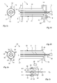
- Fig, 1a, die Vorderansicht einer erfindungsgemäßen Vorrichtung in einer ersten Ausführungsform,
- Fig. 1b die Vorrichtung aus Fig. 1a in einem Längsschnitt,
- Fig 2a, die Vorderansicht einer erfindungsgemäßen Vorrichtung in einer zweiten Ausführungsform,
- Fig 2b die Vorrichtung nach Fig. 2a in einem Längsschnitt und
- Fig 2c die Sauerstoffversorgung der Ausführungsform nach Fig. 2a,2b.
- 1a, the front view of a device according to the invention in a first embodiment,
- FIG. 1b shows the device from FIG. 1a in a longitudinal section, FIG.
- 2a, the front view of a device according to the invention in a second embodiment,
- 2b shows the device according to Fig. 2a in a longitudinal section and
- 2c, the oxygen supply of the embodiment of Fig. 2a, 2b.
Bei der in den Figs. 1a,1b gezeigten Vorrichtung 1 handelt es sich um einen Brennstoff-Sauerstoffbrenner. Die Vorrichtung 1 umfasst eine zentrale Durchführung 3 für ein Zündgas, die auch als Beobachtungskanal für eine an die Durchführung 3 angeschlossene UV-Überwachungseinheit 4 dient. Koaxial zu der Durchführung 3 ist eine Brennstoffzuführung 5 angeordnet, die der Einleitung eines Brennstoffs in einen metallurgischen Behandlungsraum 6 dient. Koaxial um die Brennstoffzuführung 5 herum ist eine Sauerstoffzuführung 8 angeordnet. Die Sauerstoffzuführung 8 ist mittels sich über nahezu die gesamte Längserstreckung der Sauerstoffzuführung 8 angeordneter Trennwände 9,10 in zwei strömungstechnisch voneinander getrennte Sauerstoffzuleitungskanäle 12,13 unterteilt, in die jeweils separate Versorgungsleitungen 14,15 einmünden. Die Versorgungsleitungen 14,15 sind über ein Drei-Wege-Ventil 17 mit einer Sauerstoff-Hauptleitung 18 verbunden, über die Sauerstoff aus einem hier nicht gezeigten Vorratsbehälter, beispielsweise einem Sauerstofftank, herangeführt wird. Die Vorrichtung 1 kann im Übrigen in bekannter und daher hier nicht gezeigter Weise mit einer Kühlung ausgerüstet sein.In the in FIGS. 1a, 1b shown
Beim Betrieb der Vorrichtung 1 wird flüssiger oder gasförmiger Brennstoff, im Ausführungsbeispiel Erdgas, über einen Brennstoffanschluss 20 in die Brennstoffzuführung 5 und von dort in einer Menge von 20 bis 80 m3/h und mit einer Geschwindigkeit im Bereich von 15 - 50 m/s in den Behandlungsraum 6 eingebracht. Über zumindest eine der Sauerstoffzuleitungskanäle 12,13 wird Sauerstoff gleichfalls in den Behandlungsraum 6 eingebracht, wobei durch eine entsprechende Einstellung am Drei-Wege-Ventil 17 der Durchfluss durch die Versorgungsleitungen 14,15 und damit durch die Sauerstoffzuführungen 12,13 jeweils genau eingestellt werden kann. Sauerstoff und Brennstoff vermischen sich innerhalb des Behandlungsraumes 6 im Vorfeld der Brennermündung 21. Über einen Zündgasanschluss 22 wird ein Zündgas durch die Durchführung 3 in den Behandlungsraum 6 eingeleitet, das für die Zündung des Brennstoff-Sauerstoff-Gemisches und die anschließenden Ausbildung einer Flamme vor der Brennermündung 21 sorgt.During operation of the
Die sich vor der Mündung 21 des Brenners ausbildende Flamme kann innerhalb des Behandlungsraumes 6 längs einer vertikalen Ebene verschwenkt werden. Hierzu wird das Strömungsverhältnis für die durch die Leitungen 14,15 bzw. die Sauerstoffkanäle 12,13 geführten Sauerstoffmengen verändert. Je mehr Sauerstoff anteilig durch den im Bild oben angeordneten Sauerstoffkanal 13 geführt wird, desto mehr verschwenkt die Flamme in Richtung nach oben, je mehr Sauerstoff anteilig durch den unteren Sauerstoffkanal 12 geführt wird, desto mehr senkt sich die Flamme im Behandlungsraum 6 nach unten. Durch die alternierende Versorgung der Sauerstoffkanäle 12,13 mit einer großen bzw. geringen Menge an Sauerstoff kann die Flamme auch periodisch auf und ab verfahren werden. Die Vorrichtung 1 bietet so eine kostengünstige Möglichkeit, die Position der Flamme innerhalb des Behandlungsraumes 6 kontinuierlich durch Verschwenken zu verändern, ohne dass es hierzu einer aufwändigen baulichen Veränderung in der Wand des Behandlungsraumes 6 oder einer schwenkbaren Aufhängung des Brenners bedarf.The flame forming in front of the
Bei der in den Figuren 2a-2c gezeigte Vorrichtung 30 sind solche Merkmale, die gleichartig zu denen der Vorrichtung 1 sind, mit gleichen Bezugsziffern bezeichnet. Die Vorrichtung 30 unterscheidet sich von der Vorrichtung 1 lediglich im Aufbau der Sauerstoffzuführung 32. Während die Sauerstoffzuführung 8 bei der Vorrichtung 1 in zwei Strömungskanäle 13,14 unterteilt ist, ist die Sauerstoffzuführung 32 mit Hilfe von zwei Strömungstrennern in Form von zumindest weitgehend gasdichten Zwischenwänden 33,34,35 in drei Sauerstoffzuleitungskanäle 36,37,38 unterteilt. Die Sauerstoffzuleitungskanäle 36,37,38 stehen jeweils mit Versorgungsleitungen 39,40,41 in Strömungsverbindung. Die Versorgungsleitungen 39,40,41 sind über einen Verteiler 42 an eine Sauerstoff-Hauptleitung 43 angeschlossen. Zur Steuerung der Strömungsdurchflüsse in den Versorgungsleitungen 39,40,41 sind in diesen jeweils strömungssteuernde Armaturen, beispielsweise Magnetventile 45,46,47 vorgesehen, die von einer zentralen Steuereinheit 49 nach einem vorgegebenen Programm angesteuert werden können. Die Magnetventile 45,46,47 sind jeweils mit einem Bypass 51,52,53 versehen, um auch im Falle eines geschlossenen Magnetventils einen minimalen Strömungsdurchfluss in jeder der Versorgungsleitungen 39,40,41 zu gewährleisten.In the
Beim Betrieb der Vorrichtung 30 wird Brennstoff, beispielsweise Erdgas, über die Brennstoffzuführung 5 in den Behandlungsraum 6 eingeleitet. Gleichzeitig wird über mindestens eine der Sauerstoffzuleitungskanäle 36,37,38 Sauerstoff aus der Sauerstoff-Hauptleitung 43 über die Versorgungsleitungen 39,40,41 in den Behandlungsraum 6 eingeleitet. Nach Zündung bildet sich im Behandlungsraum 6 vor der Brennermündung 21 eine Flamme aus.During operation of the
Um die Position der Flamme im Behandlungsraum 6 zu verändern, werden die durch die Sauerstoffkanäle 36,37,38 geführten Sauerstoffströme mittels Ansteuerung der Magnetventile 45,46,47 durch die Steuereinheit 49 eingestellt. Eine Asymmetrie in den durch die Sauerstoffzuleitungskanäle 36,37,38 geführten Sauerstoffströme führt zu einer entsprechenden Asymmetrie der Flamme im Behandlungsraum 6. Durch eine zyklische Ansteuerung der Magnetventile 45,46,47 und des damit verbundenen zyklischen Verlaufs der Sauerstoffströme in den Sauerstoffzuleitungskanälen 36,37,38 gelingt eine Rotation der Flamme im Behandlungsraum 6. Durch eine geeignete Wahl der jeweiligen Durchflussmengen und der zeitlichen Abfolge der Ansteuerung kann die Flammenausbreitung und die Rotationsgeschwindigkeit in einem weiten Bereich frei eingestellt und dem jeweiligen Behandlungsraum individuell angepasst werden.In order to change the position of the flame in the
Es ist bei der Vorrichtung 30 durch eine geeignete Wahl der entsprechenden Strömungsdurchflüsse, auch möglich, die Flamme längs einer Ebene, die nicht vertikal sein muss, im Behandlungsraum 6 zu verschwenken. Die hierzu erforderlichen Strömungsdurchflüsse werden beispielsweise vor Beginn der Behandlung empirisch ermittelt.It is possible in the
Die Vorrichtungen 1,30 können ohne umfangreiche bauliche Maßnahmen auch in bestehende Behandlungsräume eingebaut werden. Sie sind preiswert im Aufbau und leicht zu bedienen.The
Claims (11)
dadurch gekennzeichnet, dass die Zuführungskanäle (12,13,26,37,38) für das zweite Brennmedium jeweils mit strömungstechnisch voneinander getrennten Versorgungsleitungen (14,15,39,40,41) verbunden sind, in denen Einrichtungen (17,45,46,47) zur separaten Regelung des Strömungsdurchflusses vorgesehen sind.Apparatus for injecting combustion media, such as fuel or oxidant, into a metallurgical treatment space (6), with one or more supply channels (5) for a first fuel and at least two supply channels (12, 13, 26, 37, 38) for a second fuel which terminate in a mouth region (21) of the device,
characterized in that the supply channels (12,13,26,37,38) for the second fuel medium in each case with fluidically separated supply lines (14,15,39,40,41) are connected, in which means (17,45,46 , 47) are provided for separate control of the flow rate.
Priority Applications (2)
| Application Number | Priority Date | Filing Date | Title |
|---|---|---|---|
| SI200731825A SI1821036T1 (en) | 2006-02-21 | 2007-01-23 | Burner |
| PL07100966T PL1821036T3 (en) | 2006-02-21 | 2007-01-23 | Burner |
Applications Claiming Priority (1)
| Application Number | Priority Date | Filing Date | Title |
|---|---|---|---|
| DE102006007979A DE102006007979A1 (en) | 2006-02-21 | 2006-02-21 | burner |
Publications (3)
| Publication Number | Publication Date |
|---|---|
| EP1821036A2 true EP1821036A2 (en) | 2007-08-22 |
| EP1821036A3 EP1821036A3 (en) | 2015-04-01 |
| EP1821036B1 EP1821036B1 (en) | 2016-06-22 |
Family
ID=38050285
Family Applications (1)
| Application Number | Title | Priority Date | Filing Date |
|---|---|---|---|
| EP07100966.6A Active EP1821036B1 (en) | 2006-02-21 | 2007-01-23 | Burner |
Country Status (5)
| Country | Link |
|---|---|
| EP (1) | EP1821036B1 (en) |
| DE (1) | DE102006007979A1 (en) |
| ES (1) | ES2590303T3 (en) |
| PL (1) | PL1821036T3 (en) |
| SI (1) | SI1821036T1 (en) |
Cited By (1)
| Publication number | Priority date | Publication date | Assignee | Title |
|---|---|---|---|---|
| EP2166284A3 (en) * | 2008-09-17 | 2017-11-01 | Messer Group GmbH | Burner and method for operating same |
Families Citing this family (1)
| Publication number | Priority date | Publication date | Assignee | Title |
|---|---|---|---|---|
| DE102010061496A1 (en) * | 2010-12-22 | 2012-06-28 | Thyssenkrupp Polysius Ag | A tubular burner and method of operating a tubular burner |
Citations (6)
| Publication number | Priority date | Publication date | Assignee | Title |
|---|---|---|---|---|
| WO1996027761A1 (en) * | 1995-03-07 | 1996-09-12 | Luminis Pty. Ltd. | Variable flame precessing jet nozzle |
| EP1204769A1 (en) * | 1999-05-15 | 2002-05-15 | Messer Griesheim Gmbh | Device and method for spraying natural gas and/or oxygen |
| DE10156376A1 (en) * | 2001-11-16 | 2003-06-05 | Messer Griesheim Gmbh | Rotary furnace burner nozzle contains coaxial fuel and oxygen feeds and connects flowably to variable vorticizer to permit air or oxygen or mixed work. |
| DE69632672T2 (en) * | 1995-09-15 | 2005-06-09 | L'Air Liquide, S.A. a Directoire et Conseil de Surveillance pour l'Etude et l'Exploitation des Procédés Georges Claude | A method of combining oxidant and fuel in a coaxial fuel and oxidant oxygen-fuel burner |
| DE102004037620A1 (en) * | 2004-08-02 | 2006-02-23 | Air Liquide Deutschland Gmbh | Fuel-oxygen-burner for use in e.g. glass furnaces, has burner body with oxidizing agent supply and pipe shaped fuel supply, which is axially movable into mixed and combustion chamber of burning piece |
| DE102005023435A1 (en) * | 2005-05-20 | 2006-11-30 | Linde Ag | Gas burner has jacket pipe and outlet of jacket pipe is divided into at least two ring pieces which can be subjected with different masses gas or types of gas |
-
2006
- 2006-02-21 DE DE102006007979A patent/DE102006007979A1/en not_active Ceased
-
2007
- 2007-01-23 ES ES07100966.6T patent/ES2590303T3/en active Active
- 2007-01-23 SI SI200731825A patent/SI1821036T1/en unknown
- 2007-01-23 PL PL07100966T patent/PL1821036T3/en unknown
- 2007-01-23 EP EP07100966.6A patent/EP1821036B1/en active Active
Patent Citations (6)
| Publication number | Priority date | Publication date | Assignee | Title |
|---|---|---|---|---|
| WO1996027761A1 (en) * | 1995-03-07 | 1996-09-12 | Luminis Pty. Ltd. | Variable flame precessing jet nozzle |
| DE69632672T2 (en) * | 1995-09-15 | 2005-06-09 | L'Air Liquide, S.A. a Directoire et Conseil de Surveillance pour l'Etude et l'Exploitation des Procédés Georges Claude | A method of combining oxidant and fuel in a coaxial fuel and oxidant oxygen-fuel burner |
| EP1204769A1 (en) * | 1999-05-15 | 2002-05-15 | Messer Griesheim Gmbh | Device and method for spraying natural gas and/or oxygen |
| DE10156376A1 (en) * | 2001-11-16 | 2003-06-05 | Messer Griesheim Gmbh | Rotary furnace burner nozzle contains coaxial fuel and oxygen feeds and connects flowably to variable vorticizer to permit air or oxygen or mixed work. |
| DE102004037620A1 (en) * | 2004-08-02 | 2006-02-23 | Air Liquide Deutschland Gmbh | Fuel-oxygen-burner for use in e.g. glass furnaces, has burner body with oxidizing agent supply and pipe shaped fuel supply, which is axially movable into mixed and combustion chamber of burning piece |
| DE102005023435A1 (en) * | 2005-05-20 | 2006-11-30 | Linde Ag | Gas burner has jacket pipe and outlet of jacket pipe is divided into at least two ring pieces which can be subjected with different masses gas or types of gas |
Cited By (2)
| Publication number | Priority date | Publication date | Assignee | Title |
|---|---|---|---|---|
| EP2166284A3 (en) * | 2008-09-17 | 2017-11-01 | Messer Group GmbH | Burner and method for operating same |
| EP2166284B1 (en) | 2008-09-17 | 2020-11-11 | Messer Group GmbH | Rotary drum furnace and method of operating |
Also Published As
| Publication number | Publication date |
|---|---|
| EP1821036A3 (en) | 2015-04-01 |
| ES2590303T3 (en) | 2016-11-21 |
| SI1821036T1 (en) | 2016-10-28 |
| PL1821036T3 (en) | 2017-08-31 |
| EP1821036B1 (en) | 2016-06-22 |
| DE102006007979A1 (en) | 2007-09-06 |
Similar Documents
| Publication | Publication Date | Title |
|---|---|---|
| EP0001391B1 (en) | Double-walled tubular device for the cooling of endless profiles | |
| EP3327366B1 (en) | Air outlet for tempering a room | |
| EP1821036B1 (en) | Burner | |
| EP2118565A1 (en) | Burner | |
| EP1730442A1 (en) | Gas injector | |
| DE2730886A1 (en) | METHOD AND DEVICE FOR PRODUCING FIBERS, ESPECIALLY FIBERGLASS | |
| DE486447C (en) | Process for melting down raw materials or mixtures thereof, especially for glass production | |
| DE4317733A1 (en) | Gas-supply adjuster for melting furnace - delivers in separate currents to reaction chamber and adjusts their outlet speeds | |
| DE60118489T2 (en) | Three-tube burners, in particular for glass and steel melting furnaces and fuel and oxidant injection methods in such a burner | |
| EP0657390B1 (en) | Method and disposition for controlling the burning process in a glass tank furnace | |
| DE3540889A1 (en) | METHOD AND LANCE FOR FORMING A FIRE-RESISTANT MATERIAL UNDER SPRAYING PARTICLE-SHAPED EXOTHERM OXIDIZABLE MATERIALS | |
| EP0198332B1 (en) | Nozzle mixing gas-oxygen burner | |
| DE1596552B2 (en) | DEVICE FOR THE PRODUCTION OF FEDES FROM MINERAL MATERIAL, PREFERABLY GLASS FEDES | |
| DE4329646C2 (en) | Ventilation component with a device for mixing air flowing through this component | |
| DE10248530B4 (en) | Oxygen lance for high-temperature gasification of waste, and method for operating the same | |
| DE4010134A1 (en) | Air-conditioning supply unit - has ceiling-mounted distributor housing with lateral nozzles and central bottom air outlet | |
| DE3324050A1 (en) | DEVICE FOR IMPLEMENTING A GAS-SHAPED MEDIUM INTO A FURNACE OR THE LIKE. | |
| DE1596575C (en) | Method and device for regulating the temperature of glass in the molten state | |
| DE1471835B2 (en) | Device for the production of flat glass | |
| AT284182B (en) | BURNERS FOR MELTING AND / OR REFRESHING METALS | |
| DE3634749C2 (en) | ||
| EP0025080A2 (en) | Process and arrangement for feeding comminuted solid fuel to a fluidized bed furnace | |
| DE2321853A1 (en) | METHOD AND DEVICE FOR BLOWING WITH FLUID JETS CONTROLLABLE IMPULSES FOR TREATMENT OF METAL MELT | |
| DE1451428B1 (en) | Liquid burners for metallurgical ovens | |
| EP0699634A2 (en) | Industrial furnace, particularly a glass-melting furnace |
Legal Events
| Date | Code | Title | Description |
|---|---|---|---|
| PUAI | Public reference made under article 153(3) epc to a published international application that has entered the european phase |
Free format text: ORIGINAL CODE: 0009012 |
|
| AK | Designated contracting states |
Kind code of ref document: A2 Designated state(s): AT BE BG CH CY CZ DE DK EE ES FI FR GB GR HU IE IS IT LI LT LU LV MC NL PL PT RO SE SI SK TR |
|
| AX | Request for extension of the european patent |
Extension state: AL BA HR MK YU |
|
| RAP1 | Party data changed (applicant data changed or rights of an application transferred) |
Owner name: MESSER GROUP GMBH |
|
| PUAL | Search report despatched |
Free format text: ORIGINAL CODE: 0009013 |
|
| AK | Designated contracting states |
Kind code of ref document: A3 Designated state(s): AT BE BG CH CY CZ DE DK EE ES FI FR GB GR HU IE IS IT LI LT LU LV MC NL PL PT RO SE SI SK TR |
|
| AX | Request for extension of the european patent |
Extension state: AL BA HR MK RS |
|
| RIC1 | Information provided on ipc code assigned before grant |
Ipc: F23D 14/22 20060101AFI20150226BHEP Ipc: F23D 14/84 20060101ALI20150226BHEP |
|
| 17P | Request for examination filed |
Effective date: 20151001 |
|
| RBV | Designated contracting states (corrected) |
Designated state(s): AT BE BG CH CY CZ DE DK EE ES FI FR GB GR HU IE IS IT LI LT LU LV MC NL PL PT RO SE SI SK TR |
|
| AKX | Designation fees paid |
Designated state(s): AT BE BG CH CY CZ DE DK EE ES FI FR GB GR HU IE IS IT LI LT LU LV MC NL PL PT RO SE SI SK TR |
|
| AXX | Extension fees paid |
Extension state: BA Extension state: RS Extension state: MK Extension state: AL Extension state: HR |
|
| GRAP | Despatch of communication of intention to grant a patent |
Free format text: ORIGINAL CODE: EPIDOSNIGR1 |
|
| INTG | Intention to grant announced |
Effective date: 20160218 |
|
| GRAS | Grant fee paid |
Free format text: ORIGINAL CODE: EPIDOSNIGR3 |
|
| GRAA | (expected) grant |
Free format text: ORIGINAL CODE: 0009210 |
|
| AK | Designated contracting states |
Kind code of ref document: B1 Designated state(s): AT BE BG CH CY CZ DE DK EE ES FI FR GB GR HU IE IS IT LI LT LU LV MC NL PL PT RO SE SI SK TR |
|
| REG | Reference to a national code |
Ref country code: GB Ref legal event code: FG4D Free format text: NOT ENGLISH |
|
| REG | Reference to a national code |
Ref country code: CH Ref legal event code: EP |
|
| REG | Reference to a national code |
Ref country code: IE Ref legal event code: FG4D Free format text: LANGUAGE OF EP DOCUMENT: GERMAN |
|
| REG | Reference to a national code |
Ref country code: AT Ref legal event code: REF Ref document number: 807886 Country of ref document: AT Kind code of ref document: T Effective date: 20160715 |
|
| REG | Reference to a national code |
Ref country code: DE Ref legal event code: R096 Ref document number: 502007014884 Country of ref document: DE |
|
| REG | Reference to a national code |
Ref country code: RO Ref legal event code: EPE |
|
| REG | Reference to a national code |
Ref country code: LT Ref legal event code: MG4D |
|
| REG | Reference to a national code |
Ref country code: NL Ref legal event code: MP Effective date: 20160622 |
|
| PG25 | Lapsed in a contracting state [announced via postgrant information from national office to epo] |
Ref country code: FI Free format text: LAPSE BECAUSE OF FAILURE TO SUBMIT A TRANSLATION OF THE DESCRIPTION OR TO PAY THE FEE WITHIN THE PRESCRIBED TIME-LIMIT Effective date: 20160622 Ref country code: LT Free format text: LAPSE BECAUSE OF FAILURE TO SUBMIT A TRANSLATION OF THE DESCRIPTION OR TO PAY THE FEE WITHIN THE PRESCRIBED TIME-LIMIT Effective date: 20160622 |
|
| REG | Reference to a national code |
Ref country code: ES Ref legal event code: FG2A Ref document number: 2590303 Country of ref document: ES Kind code of ref document: T3 Effective date: 20161121 |
|
| PG25 | Lapsed in a contracting state [announced via postgrant information from national office to epo] |
Ref country code: GR Free format text: LAPSE BECAUSE OF FAILURE TO SUBMIT A TRANSLATION OF THE DESCRIPTION OR TO PAY THE FEE WITHIN THE PRESCRIBED TIME-LIMIT Effective date: 20160923 Ref country code: SE Free format text: LAPSE BECAUSE OF FAILURE TO SUBMIT A TRANSLATION OF THE DESCRIPTION OR TO PAY THE FEE WITHIN THE PRESCRIBED TIME-LIMIT Effective date: 20160622 Ref country code: LV Free format text: LAPSE BECAUSE OF FAILURE TO SUBMIT A TRANSLATION OF THE DESCRIPTION OR TO PAY THE FEE WITHIN THE PRESCRIBED TIME-LIMIT Effective date: 20160622 Ref country code: NL Free format text: LAPSE BECAUSE OF FAILURE TO SUBMIT A TRANSLATION OF THE DESCRIPTION OR TO PAY THE FEE WITHIN THE PRESCRIBED TIME-LIMIT Effective date: 20160622 |
|
| REG | Reference to a national code |
Ref country code: FR Ref legal event code: PLFP Year of fee payment: 11 |
|
| PG25 | Lapsed in a contracting state [announced via postgrant information from national office to epo] |
Ref country code: EE Free format text: LAPSE BECAUSE OF FAILURE TO SUBMIT A TRANSLATION OF THE DESCRIPTION OR TO PAY THE FEE WITHIN THE PRESCRIBED TIME-LIMIT Effective date: 20160622 Ref country code: IS Free format text: LAPSE BECAUSE OF FAILURE TO SUBMIT A TRANSLATION OF THE DESCRIPTION OR TO PAY THE FEE WITHIN THE PRESCRIBED TIME-LIMIT Effective date: 20161022 |
|
| PG25 | Lapsed in a contracting state [announced via postgrant information from national office to epo] |
Ref country code: PT Free format text: LAPSE BECAUSE OF FAILURE TO SUBMIT A TRANSLATION OF THE DESCRIPTION OR TO PAY THE FEE WITHIN THE PRESCRIBED TIME-LIMIT Effective date: 20161024 |
|
| REG | Reference to a national code |
Ref country code: DE Ref legal event code: R097 Ref document number: 502007014884 Country of ref document: DE |
|
| PLBE | No opposition filed within time limit |
Free format text: ORIGINAL CODE: 0009261 |
|
| STAA | Information on the status of an ep patent application or granted ep patent |
Free format text: STATUS: NO OPPOSITION FILED WITHIN TIME LIMIT |
|
| 26N | No opposition filed |
Effective date: 20170323 |
|
| PG25 | Lapsed in a contracting state [announced via postgrant information from national office to epo] |
Ref country code: DK Free format text: LAPSE BECAUSE OF FAILURE TO SUBMIT A TRANSLATION OF THE DESCRIPTION OR TO PAY THE FEE WITHIN THE PRESCRIBED TIME-LIMIT Effective date: 20160622 Ref country code: BE Free format text: LAPSE BECAUSE OF NON-PAYMENT OF DUE FEES Effective date: 20170131 |
|
| REG | Reference to a national code |
Ref country code: CH Ref legal event code: PL |
|
| GBPC | Gb: european patent ceased through non-payment of renewal fee |
Effective date: 20170123 |
|
| PG25 | Lapsed in a contracting state [announced via postgrant information from national office to epo] |
Ref country code: MC Free format text: LAPSE BECAUSE OF FAILURE TO SUBMIT A TRANSLATION OF THE DESCRIPTION OR TO PAY THE FEE WITHIN THE PRESCRIBED TIME-LIMIT Effective date: 20160622 |
|
| PG25 | Lapsed in a contracting state [announced via postgrant information from national office to epo] |
Ref country code: CH Free format text: LAPSE BECAUSE OF NON-PAYMENT OF DUE FEES Effective date: 20170131 Ref country code: LI Free format text: LAPSE BECAUSE OF NON-PAYMENT OF DUE FEES Effective date: 20170131 |
|
| REG | Reference to a national code |
Ref country code: IE Ref legal event code: MM4A |
|
| PG25 | Lapsed in a contracting state [announced via postgrant information from national office to epo] |
Ref country code: GB Free format text: LAPSE BECAUSE OF NON-PAYMENT OF DUE FEES Effective date: 20170123 Ref country code: LU Free format text: LAPSE BECAUSE OF NON-PAYMENT OF DUE FEES Effective date: 20170123 |
|
| REG | Reference to a national code |
Ref country code: FR Ref legal event code: PLFP Year of fee payment: 12 |
|
| REG | Reference to a national code |
Ref country code: BE Ref legal event code: MM Effective date: 20170131 |
|
| PG25 | Lapsed in a contracting state [announced via postgrant information from national office to epo] |
Ref country code: IE Free format text: LAPSE BECAUSE OF NON-PAYMENT OF DUE FEES Effective date: 20170123 |
|
| PG25 | Lapsed in a contracting state [announced via postgrant information from national office to epo] |
Ref country code: HU Free format text: LAPSE BECAUSE OF FAILURE TO SUBMIT A TRANSLATION OF THE DESCRIPTION OR TO PAY THE FEE WITHIN THE PRESCRIBED TIME-LIMIT; INVALID AB INITIO Effective date: 20070123 |
|
| PG25 | Lapsed in a contracting state [announced via postgrant information from national office to epo] |
Ref country code: BG Free format text: LAPSE BECAUSE OF FAILURE TO SUBMIT A TRANSLATION OF THE DESCRIPTION OR TO PAY THE FEE WITHIN THE PRESCRIBED TIME-LIMIT Effective date: 20160622 |
|
| PG25 | Lapsed in a contracting state [announced via postgrant information from national office to epo] |
Ref country code: CY Free format text: LAPSE BECAUSE OF NON-PAYMENT OF DUE FEES Effective date: 20160622 |
|
| PG25 | Lapsed in a contracting state [announced via postgrant information from national office to epo] |
Ref country code: TR Free format text: LAPSE BECAUSE OF FAILURE TO SUBMIT A TRANSLATION OF THE DESCRIPTION OR TO PAY THE FEE WITHIN THE PRESCRIBED TIME-LIMIT Effective date: 20160622 |
|
| PGFP | Annual fee paid to national office [announced via postgrant information from national office to epo] |
Ref country code: RO Payment date: 20201223 Year of fee payment: 15 |
|
| PGFP | Annual fee paid to national office [announced via postgrant information from national office to epo] |
Ref country code: IT Payment date: 20201211 Year of fee payment: 15 |
|
| REG | Reference to a national code |
Ref country code: DE Ref legal event code: R081 Ref document number: 502007014884 Country of ref document: DE Owner name: MESSER SE & CO. KGAA, DE Free format text: FORMER OWNER: MESSER GROUP GMBH, 65812 BAD SODEN, DE |
|
| PGFP | Annual fee paid to national office [announced via postgrant information from national office to epo] |
Ref country code: SI Payment date: 20211220 Year of fee payment: 16 |
|
| PG25 | Lapsed in a contracting state [announced via postgrant information from national office to epo] |
Ref country code: RO Free format text: LAPSE BECAUSE OF NON-PAYMENT OF DUE FEES Effective date: 20220123 |
|
| PG25 | Lapsed in a contracting state [announced via postgrant information from national office to epo] |
Ref country code: IT Free format text: LAPSE BECAUSE OF NON-PAYMENT OF DUE FEES Effective date: 20220123 |
|
| PGFP | Annual fee paid to national office [announced via postgrant information from national office to epo] |
Ref country code: SK Payment date: 20221213 Year of fee payment: 17 Ref country code: CZ Payment date: 20221227 Year of fee payment: 17 |
|
| PGFP | Annual fee paid to national office [announced via postgrant information from national office to epo] |
Ref country code: PL Payment date: 20221214 Year of fee payment: 17 |
|
| PGFP | Annual fee paid to national office [announced via postgrant information from national office to epo] |
Ref country code: ES Payment date: 20230216 Year of fee payment: 17 Ref country code: AT Payment date: 20221228 Year of fee payment: 17 |
|
| PGFP | Annual fee paid to national office [announced via postgrant information from national office to epo] |
Ref country code: DE Payment date: 20230131 Year of fee payment: 17 |
|
| PG25 | Lapsed in a contracting state [announced via postgrant information from national office to epo] |
Ref country code: SI Free format text: LAPSE BECAUSE OF NON-PAYMENT OF DUE FEES Effective date: 20230124 |
|
| REG | Reference to a national code |
Ref country code: SI Ref legal event code: KO00 Effective date: 20231017 |
|
| PGFP | Annual fee paid to national office [announced via postgrant information from national office to epo] |
Ref country code: FR Payment date: 20231212 Year of fee payment: 18 |
|
| PGFP | Annual fee paid to national office [announced via postgrant information from national office to epo] |
Ref country code: PL Payment date: 20231213 Year of fee payment: 18 |
|
| PGFP | Annual fee paid to national office [announced via postgrant information from national office to epo] |
Ref country code: ES Payment date: 20240208 Year of fee payment: 18 |