EP1820977B1 - Verbindungsbeschlag für Hohlplatten - Google Patents
Verbindungsbeschlag für Hohlplatten Download PDFInfo
- Publication number
- EP1820977B1 EP1820977B1 EP07002458A EP07002458A EP1820977B1 EP 1820977 B1 EP1820977 B1 EP 1820977B1 EP 07002458 A EP07002458 A EP 07002458A EP 07002458 A EP07002458 A EP 07002458A EP 1820977 B1 EP1820977 B1 EP 1820977B1
- Authority
- EP
- European Patent Office
- Prior art keywords
- housing
- connection fitting
- fitting according
- hinge
- fastening plate
- Prior art date
- Legal status (The legal status is an assumption and is not a legal conclusion. Google has not performed a legal analysis and makes no representation as to the accuracy of the status listed.)
- Active
Links
Images

Classifications
-
- F—MECHANICAL ENGINEERING; LIGHTING; HEATING; WEAPONS; BLASTING
- F16—ENGINEERING ELEMENTS AND UNITS; GENERAL MEASURES FOR PRODUCING AND MAINTAINING EFFECTIVE FUNCTIONING OF MACHINES OR INSTALLATIONS; THERMAL INSULATION IN GENERAL
- F16B—DEVICES FOR FASTENING OR SECURING CONSTRUCTIONAL ELEMENTS OR MACHINE PARTS TOGETHER, e.g. NAILS, BOLTS, CIRCLIPS, CLAMPS, CLIPS OR WEDGES; JOINTS OR JOINTING
- F16B12/00—Jointing of furniture or the like, e.g. hidden from exterior
- F16B12/10—Jointing of furniture or the like, e.g. hidden from exterior using pegs, bolts, tenons, clamps, clips, or the like
- F16B12/12—Jointing of furniture or the like, e.g. hidden from exterior using pegs, bolts, tenons, clamps, clips, or the like for non-metal furniture parts, e.g. made of wood, of plastics
- F16B12/20—Jointing of furniture or the like, e.g. hidden from exterior using pegs, bolts, tenons, clamps, clips, or the like for non-metal furniture parts, e.g. made of wood, of plastics using clamps, clips, wedges, sliding bolts, or the like
- F16B12/2009—Jointing of furniture or the like, e.g. hidden from exterior using pegs, bolts, tenons, clamps, clips, or the like for non-metal furniture parts, e.g. made of wood, of plastics using clamps, clips, wedges, sliding bolts, or the like actuated by rotary motion
- F16B12/2027—Jointing of furniture or the like, e.g. hidden from exterior using pegs, bolts, tenons, clamps, clips, or the like for non-metal furniture parts, e.g. made of wood, of plastics using clamps, clips, wedges, sliding bolts, or the like actuated by rotary motion with rotating excenters or wedges
- F16B12/2036—Jointing of furniture or the like, e.g. hidden from exterior using pegs, bolts, tenons, clamps, clips, or the like for non-metal furniture parts, e.g. made of wood, of plastics using clamps, clips, wedges, sliding bolts, or the like actuated by rotary motion with rotating excenters or wedges with rotating excenters or wedges acting on a head of a pin or screw
-
- A—HUMAN NECESSITIES
- A47—FURNITURE; DOMESTIC ARTICLES OR APPLIANCES; COFFEE MILLS; SPICE MILLS; SUCTION CLEANERS IN GENERAL
- A47B—TABLES; DESKS; OFFICE FURNITURE; CABINETS; DRAWERS; GENERAL DETAILS OF FURNITURE
- A47B2230/00—Furniture jointing; Furniture with such jointing
- A47B2230/0029—Dowels
- A47B2230/0033—Expansible dowels or dowel-pins
-
- F—MECHANICAL ENGINEERING; LIGHTING; HEATING; WEAPONS; BLASTING
- F16—ENGINEERING ELEMENTS AND UNITS; GENERAL MEASURES FOR PRODUCING AND MAINTAINING EFFECTIVE FUNCTIONING OF MACHINES OR INSTALLATIONS; THERMAL INSULATION IN GENERAL
- F16B—DEVICES FOR FASTENING OR SECURING CONSTRUCTIONAL ELEMENTS OR MACHINE PARTS TOGETHER, e.g. NAILS, BOLTS, CIRCLIPS, CLAMPS, CLIPS OR WEDGES; JOINTS OR JOINTING
- F16B5/00—Joining sheets or plates, e.g. panels, to one another or to strips or bars parallel to them
- F16B5/01—Joining sheets or plates, e.g. panels, to one another or to strips or bars parallel to them by means of fastening elements specially adapted for honeycomb panels
Definitions
- the invention relates to a connection fitting for hollow plates, in particular honeycomb panels, sandwich panels or the like with a rotatably mounted in a housing clamping part which receives the head of an associated tightening bolt, wherein the housing is formed in two parts.
- connection fitting is from the EP 0 507 289 A1 known.
- the connection fitting has a housing which is connected via a flange with a pin.
- the entire connection fitting is formed in two parts, wherein At a first part connecting pin and at a second part openings for engaging the connecting pins are formed.
- the connection fitting is inserted into blind holes in a first furniture part such that the housing is flush with an end face of the first furniture part.
- the housing At the end side of the associated side, the housing has a slot through which a pull stud can pass.
- the pull stud is used for connecting the first furniture part with a second furniture part on the surface of the second furniture part.
- a clamping part In the housing, a clamping part is used, which is pivotable by means of bearing pins in an aligned transversely to the direction of the tightening bolt axis. To actuate the clamping part an elongated approach is formed on this. When pivoting the clamping part of a release in a closed position of the head of the tightening bolt is engaged behind and tightened on an eccentrically arranged clamping surface.
- the DE 298 04 267 U1 relates to a connector between two components, in particular plates.
- a pull stud is first inserted into one of the open and pivotally connected by a hinge housing parts of a housing. Subsequently, the two housing parts are then pivoted towards each other and connected to each other by means of a locking device.
- the connector or the housing are in holes on the surface of a first plate and used on the front side of a second plate.
- the pull stud has a recess on its head into which a clamping part is inserted.
- the housing has in the corresponding section a transverse bore to the longitudinal axis, in which the clamping part is rotatably mounted and is accessible from a surface of the second plate through a recess.
- connection fitting has become known.
- a bolt is inserted into a first plate and has a collar and a head at its free end.
- the connection fitting or its housing is composed of two semi-cylindrical housing parts, which are interconnected via a hinge.
- the bolt is enclosed by two housing parts before the closed connection fitting is inserted into a corresponding recess on a second plate.
- the bolt is fixed in the selected position via a screw.
- the external thread of the screw is matched to the thread of a bore, that in a final position of the screw rests a wedge below the head of the bolt.
- Hollow slabs consist of two relatively thin but firm cover plates, the cavity between them being filled with corrugated cardboard or similar material. While fittings in massive plates can be embedded in holes in the same or screwed in a simple manner, find the fittings or screws in hollow slabs no support within the cavities, so that one must confine himself in the attachment to the cover plates.
- the invention has for its object to provide a way to use a clamping part in a simplified manner in a connection fitting.
- connection fitting of the type described above, which is inventively characterized in that both housing parts are connected by a hinge with an approximately parallel to the clamping part axis axis and locked together in the closed position.
- clamping part after the two housing parts are pivoted apart, are used laterally. Subsequently, the housing parts are then pivoted together and connected in any way. This makes it possible to make the bottom of the housing of relatively strong material.
- the hinge is formed as a film hinge.
- a locking device is expediently arranged. This can consist of a below the housing at one of the two parts arranged elastic latching hook and provided on the other part latching recess.
- one of the two housing parts is connected to a mounting plate to be arranged above the hollow plate. This is in particular on the housing hinge on the housing before, wherein on the projecting part a downwardly directed pin is provided as reinforcement and anti-rotation.
- the housing has expediently partially circumferential ribs and the cover layer of the hollow plate under cross wings.
- the housing is provided on its side facing away from the hinge in the lower part with a support web. This serves to rest on a lower edge of the hollow plate. This results in a better support of the fitting in the hollow plate.
- the connecting fitting has a housing 1 with a clamping part 2 rotatably mounted therein for the head 3 of a tightening bolt 4.
- the housing 1 is composed of two housing parts 5 and 6, which are connected by an approximately parallel to the axis of the clamping part 2 extending film hinge 7 pivotally connected to each other.
- the housing part 5 consists of one piece with a mounting plate 8, which, as Fig. 3 shows above a hollow plate 9 comes to rest.
- the mounting plate 8 protrudes beyond the housing 1 and on the protruding part 9, a downwardly directed pin 10 is provided, which also engages in the hollow plate 22 and in particular serves to prevent rotation of the fitting.
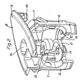
- the clamping part 2 is in the after Fig. 2 open housing 1 inserted laterally, whereupon then the housing part 6 from the housing part 5 in the closed position to Fig. 1 is pivoted.
- an elastic latching hook 11 is provided on the housing part 5 and the housing part 6 a latching recess 12th
- the housing 1 has a very solid bottom part 13, so that when inserting a tool, not shown through the opening 14 of the mounting plate 8 in the tool holder 15 of the clamping part 2, even with a firm pressure on the tool no breaking of the clamping part 2 down is to be feared.
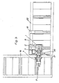
- Fig. 3 shows the connection between a hollow plate 22 and a standing perpendicular thereto further hollow plate 16.
- the bolt 4 by means of a dowel 17 in the hollow plate 16th set and engages with his head 3 in the clamping part 2 a.
- This is rotatably mounted in the housing 1 and arranged together with the mounting plate 8 in the hollow plate 22.
- the housing 1 is provided with a part of the same circumferential ribs 18 and a plurality of obliquely upwardly outwardly elastic wings 19.
- the housing is further provided on its side facing away from the hinge 7 in the lower part with a support bar 20. This serves to rest on a lower edge 21 of the hollow plate 22.
Landscapes
- Engineering & Computer Science (AREA)
- General Engineering & Computer Science (AREA)
- Mechanical Engineering (AREA)
- Connection Of Plates (AREA)
- Dowels (AREA)
- Body Structure For Vehicles (AREA)
- Joining Of Building Structures In Genera (AREA)
- Clamps And Clips (AREA)
Description
- Die Erfindung bezieht sich auf einen Verbindungsbeschlag für Hohlplatten, insbesondere Wabenplatten, Sandwichplatten oder dergleichen mit einem in einem Gehäuse drehbar gelagerten Spannteil, welches den Kopf eines zugehörigen Anzugsbolzens aufnimmt, wobei das Gehäuse zweiteilig ausgebildet ist.
- Ein derartiger Verbindungsbeschlag ist aus der
EP 0 507 289 A1 bekannt geworden. Der Verbindungsbeschlag weist ein Gehäuse auf, welches über einen Flansch mit einem Zapfen verbunden ist. Der gesamte Verbindungsbeschlag ist zweiteilig ausgebildet, wobei an einem ersten Teil Verbindungszapfen und an einem zweiten Teil Öffnungen zum Eingreifen der verbindungszapfen ausgebildet sind. Der Verbindungsbeschlag wird derart in Sacklochbohrungen in einem ersten Möbelteil eingesetzt, dass das Gehäuse mit einer Stirnseite des ersten Möbelteils bündig abschließt. An der der Stirnseite zugeordneten Seite weist das Gehäuse einen Schlitz auf, durch welchen ein Anzugsbolzen hindurchtreten kann. Der Anzugsbolzen wird zum Verbinden des ersten Möbelteils mit einem zweiten Möbelteil an der Oberfläche des zweiten Möbelteils eingesetzt. In das Gehäuse wird ein Spannteil eingesetzt, welches mittels Lagerzapfen in einer quer zur Ausrichtung des Anzugsbolzens ausgerichteten Achse verschwenkbar ist. Zur Betätigung des Spannteils ist an diesem ein verlängerter Ansatz ausgebildet. Beim Verschwenken des Spannteils von einer Freigabe- in eine Schließstellung wird der Kopf des Anzugsbolzens hintergriffen und über eine exzentrisch angeordnete Spannfläche angezogen. - Die
DE 298 04 267 U1 betrifft einen Verbinder zwischen zwei Bauteilen, insbesondere Platten. Um zwei Platten miteinander zu verbinden, wird zunächst ein Anzugsbolzen in eine der geöffneten und durch ein Scharnier schwenkbar verbundenen Gehäuseteile eines Gehäuses eingelegt. Anschließend werden dann die beiden Gehäuseteile aufeinander geschwenkt und mittels einer Rastvorrichtung miteinander verbunden. Der Verbinder bzw. das Gehäuse werden in Bohrungen an der Oberfläche einer ersten Platte und an der Stirnseite einer zweiten Platte eingesetzt. Der Anzugsbolzen weist an seinem Kopf eine Ausnehmung auf, in welche ein Spannteil eingesetzt wird. Das Gehäuse weist im entsprechenden Abschnitt eine Querbohrung zur Längsachse auf, in welcher das Spannteil drehbar gelagert ist und von einer Oberfläche der zweiten Platte durch eine Ausnehmung zugänglich ist. Bei einem Verdrehen des Spannteils wird der im Gehäuse längsverschiebbare Anzugsbolzen derart verschoben, dass beide Platten bis zum Anschlag aneinander gezogen und gegeneinander festgelegt werden. - Aus der
GB 2 080 907 A - Hohlplatten bestehen aus zwei relativ dünnen, jedoch festen Deckplatten, wobei der Hohlraum zwischen diesen mit Wellpappe oder ähnlichem Material ausgefüllt ist. Während Beschläge bei massiven Platten in Bohrungen derselben eingelassen oder in einfacher Weise angeschraubt werden können, finden die Beschläge oder Schrauben bei Hohlplatten keinen Halt innerhalb der Hohlräume, so dass man sich bei der Befestigung auf die Deckplatten beschränken muss.
- Bei einem Verbindungsbeschlag mit einem in einem Gehäuse drehbar gelagerten Spannteil, welches den Kopf eines zugehörigen Anzugsbolzens aufnimmt, entstehen Schwierigkeiten beim Einsetzen des Spannteils in das Gehäuse. Die zur Oberseite gerichtete Öffnung des Gehäuses soll möglichst unaufällig sein und nur zum Einsetzen eines Werkzeuges zum Drehen des Spannteiles dienen. Bei einem Einsetzen von unten und Verrasten besteht die Gefahr, das bei zu starkem Druck auf das Werkzeug das Spannteil herausfällt, da der bei Massivplatten vorhandene Boden der Bohrung fehlt.
- Der Erfindung liegt die Aufgabe zugrunde, eine Möglichkeit zu schaffen, ein Spannteil in erleichterter Weise in einen Verbindungsbeschlag einzusetzen.
- Gelöst wird diese Aufgabe durch einen Verbindungsbeschlag der eingangs beschriebenen Art, der erfindungsgemäß dadurch gekennzeichnet ist, dass beide Gehäuseteile durch ein Scharnier mit einer etwa parallel zur Spannteilachse verlaufenden Achse verbunden und in der geschlossenen Lage miteinander verrastbar sind. Nunmehr kann das Spannteil, nachdem die beiden Gehäuseteile auseinander geschwenkt sind, seitlich eingesetzt werden. Anschliessend werden dann die Gehäuseteile zusammen geschwenkt und in beliebiger Weise verbunden. Dadurch ist es möglich, den Boden des Gehäuses aus relativ festem Material zu gestalten.
- Vorzugsweise ist das Scharnier als Filmscharnier ausgebildet. Zur Verbindung der Gehäuseteile im geschlossenen Zustand des Gehäuses ist zweckmässiger Weise eine Rastvorrichtung angeordnet. Diese kann aus einem unterhalb des Gehäuses an einem der beiden Teile desselben angeordneten elastischen Rasthaken und einer am anderen Teil vorgesehenen Rastvertiefung bestehen.
- Zur Befestigung des Gehäuses in der Hohlplatte ist eines der beiden Gehäuseteile mit einer oberhalb der Hohlplatte anzuordnenden Befestigungsplatte verbunden ist. Diese steht insbesondere am Gehäusescharnier über das Gehäuse vor, wobei am vorstehenden Teil ein nach unten gerichteter Zapfen als Verstärkung und Verdrehsicherung vorgesehen ist.
- Das Gehäuse weist zweckmässig teilweise umlaufende Rippen und die Deckschicht der Hohlplatte untergreifende Flügel auf. Vorzugsweise ist das Gehäuse an seiner dem Scharnier abgewandten Seite im unteren Teil mit einen Stützsteg versehen. Dieser dient zur Anlage an einer Unterkante der Hohlplatte. Dadurch ergibt sich eine bessere Abstützung des Beschlages in der Hohlplatte.
- Die Zeichnung zeigt Ausführungsbeispiele der Erfindung. Es stellen dar:
- Figur 1
- eine perspektivische Ansicht eines Verbindungsbe- schlages mit einem Anzugsbolzen.
- Figur 2
- eine Darstellung nach
Fig. 1 im ausgeschwenktem Zustand der Gehäuseteile. - Figur 3
- zwei verbundene Wabenplatten mit einem Verbin- dungsbeschlag nach
Fig.1 , - Der Verbindungsbeschlag weist ein Gehäuse 1 mit einem darin drehbar gelagerten Spannteil 2 für den Kopf 3 eines Anzugsbolzens 4 auf.
- Das Gehäuse 1 setzt sich aus zwei Gehäuseteilen 5 und 6 zusammen, welche durch ein etwa parallel zur Achse des Spannteils 2 verlaufendes Filmscharnier 7 schwenkbar miteinander verbunden sind. Das Gehäuseteil 5 besteht aus einem Stück mit einer Befestigungsplatte 8, welche, wie
Fig. 3 zeigt oberhalb einer Hohlplatte 9 zu liegen kommt. Die Befestigungsplatte 8 steht über das Gehäuse 1 hinaus und am vorstehenden Teil 9 ist ein nach unten gerichteter Zapfen 10 vorgesehen, welcher ebenfalls in die Hohlplatte 22 eingreift und insbesondere zur Verdrehsicherung des Beschlages dient. Das Spannteil 2 wird in das nachFig. 2 geöffnete Gehäuse 1 seitlich eingesetzt, worauf dann das Gehäuseteil 6 vom Gehäuseteil 5 in die geschlossene Stellung nachFig. 1 geschwenkt wird. Zur Befestigung der Teile 5 und 6 in dieser Lage ist am Gehäuseteil 5 ein elastischer Rasthaken 11 vorgesehen und am Gehäuseteil 6 eine Rastvertiefung 12. - Wie vor allem aus
Fig. 2 ersichtlich ist, besitzt das Gehäuse 1 ein sehr festes Bodenteil 13, so dass bei einem Einführen eines nicht dargestellten Werkzeuges durch die Öffnung 14 der Befestigungsplatte 8 in die Werkzeugaufnahme 15 des Spannteiles 2 auch bei festem Druck auf das Werkzeug kein Durchbrechen des Spannteiles 2 nach unten zu befürchten ist. -
Fig. 3 zeigt die Verbindung zwischen einer Hohlplatte 22 und einer senkrecht hierzu stehenden weiteren Hohlplatte 16. Dabei ist der Bolzen 4 mittels eines Dübels 17 in der Hohlplatte 16 festgelegt und greift mit seinem Kopf 3 in das Spannteil 2 ein. Dieses ist im Gehäuse 1 drehbar gelagert und zusammen mit der Befestigungsplatte 8 in der Hohlplatte 22 angeordnet. Beim Drehen des Spannteiles 2 werden der Bolzen 4 über seinen Kopf 3 und damit die Hohlplatte 16 an die Hohlplatte 22 herangezogen und die Platten 22,16 damit fest miteinander verbunden. - Um die Abstützung des Beschlages in der Hohlplatte 22 zu verbessern, ist das Gehäuse 1 mit über einen Teil deselben umlaufenden Rippen 18 und mehreren schräg nach oben aussen stehenden elastischen Flügeln 19 versehen. Das Gehäuse ist weiterhin an seiner dem Scharnier 7 abgewandten Seite im unteren Teil mit einen Stützsteg 20 versehen. Dieser dient zur Anlage an einer Unterkante 21 der Hohlplatte 22.
Claims (10)
- Verbindungsbeschlag für Hohlplatten, insbesondere Wabenplatten, Sandwichplatten odgl. mit einem in einem Gehäuse (1) drehbar gelagerten Spannteil (2), welches den Kopf (3) eines zugehörigen Anzugsbolzens (4) aufnimmt, wobei das Gehäuse (1) zweiteilig ausgebildet ist, dadurch gekennzeichnet, dass beide Gehäuseteile (5,6) durch ein Scharnier (7) mit einer etwa parallel zur Spannteilachse verlaufenden Achse verbunden und in der geschlossenen Lage miteinander verrastbar sind.
- Verbindungsbeschlag nach Anspruch 1, dadurch gekennzeichnet, dass eines der beiden Gehäuseteile (5,6) mit einer oberhalb einer Hohlplatte (22) anzuordnenden Befestigungsplatte (8) verbunden ist.
- Verbindungsbeschlag nach Anspruch 2, dadurch gekennzeichnet, dass an der der Befestigungsplatte (8) gegenüberliegenden Seite des Gehäuses (1) ein festes Bodenteil (13) ausgebildet ist.
- Verbindungsbeschlag nach Anspruch 2 oder 3, dadurch gekennzeichnet, dass das Spannteil (2) eine Werkzeugaufnahme (15) aufweist und in der Befestigungsplatte (8) eine Öffnung (14) zum Einführen eines Werkzeuges ausgebildet ist.
- Verbindungsbeschlag nach einem der vorhergehenden Ansprüche, dadurch gekennzeichnet, dass das Scharnier als Filmscharnier (7) ausgebildet ist.
- Verbindungsbeschlag nach einem der vorhergehenden Ansprüche, dadurch gekennzeichnet, dass zur Verbindung der beiden Gehäuseteile (5, 6) im geschlossenen Zustand des Gehäuses (1) eine Rastvorrichtung (11, 12) angeordnet ist.
- Verbindungsbeschlag nach Anspruch 6, dadurch gekennzeichnet, dass die Rastvorrichtung aus einem unterhalb des Gehäuses (1) an einem der beiden Teile desselben angeordneten elastischen Rasthaken (11) und einer am anderen Teil vorgesehenen Rastvertiefung (12) besteht.
- Verbindungsbeschlag nach einem der Ansprüche 2 bis 7, dadurch gekennzeichnet, dass die Befestigungsplatte (8) insbesondere am Gehäusescharnier (7) über das Gehäuse (1) vorsteht, wobei am vorstehenden Teil (9) ein nach unten gerichteter Zapfen (10) vorgesehen ist.
- Verbindungsbeschlag nach einem der vorhergehenden Ansprüche, dadurch gekennzeichnet, dass das Gehäuse (1) teilweise umlaufende Rippen (18) und die Deckschicht der Hohlplatte (9) untergreifende Flügel (19) aufweist.
- Verbindungsbeschlag nach einem der vorhergehenden Ansprüche, dadurch gekennzeichnet, dass Gehäuse (1) an seiner dem Scharnier (7) abgewandten Seite im unteren Teil einen Stützsteg (20) aufweist.
Priority Applications (2)
| Application Number | Priority Date | Filing Date | Title |
|---|---|---|---|
| PL07002458T PL1820977T3 (pl) | 2006-02-18 | 2007-02-05 | Okucie łączące dla płyt o przekroju wydrążonym |
| SI200730802T SI1820977T1 (sl) | 2006-02-18 | 2007-02-05 | Povezovalno okovje za votle ploĺ äśe |
Applications Claiming Priority (1)
| Application Number | Priority Date | Filing Date | Title |
|---|---|---|---|
| DE202006002649U DE202006002649U1 (de) | 2006-02-18 | 2006-02-18 | Verbindungsbeschlag für Hohlplatten |
Publications (2)
| Publication Number | Publication Date |
|---|---|
| EP1820977A1 EP1820977A1 (de) | 2007-08-22 |
| EP1820977B1 true EP1820977B1 (de) | 2011-10-12 |
Family
ID=36314403
Family Applications (1)
| Application Number | Title | Priority Date | Filing Date |
|---|---|---|---|
| EP07002458A Active EP1820977B1 (de) | 2006-02-18 | 2007-02-05 | Verbindungsbeschlag für Hohlplatten |
Country Status (7)
| Country | Link |
|---|---|
| EP (1) | EP1820977B1 (de) |
| AT (1) | ATE528516T1 (de) |
| DE (1) | DE202006002649U1 (de) |
| DK (1) | DK1820977T3 (de) |
| ES (1) | ES2375217T3 (de) |
| PL (1) | PL1820977T3 (de) |
| SI (1) | SI1820977T1 (de) |
Cited By (1)
| Publication number | Priority date | Publication date | Assignee | Title |
|---|---|---|---|---|
| US20220381277A1 (en) * | 2021-05-25 | 2022-12-01 | Textron Aviation Inc. | Fastening system with concealed fastener |
Families Citing this family (4)
| Publication number | Priority date | Publication date | Assignee | Title |
|---|---|---|---|---|
| DE102007048975A1 (de) * | 2007-10-12 | 2009-04-16 | Böllhoff Verbindungstechnik GmbH | Schnellbefestigungseinrichtung |
| DE202010016369U1 (de) | 2010-11-16 | 2011-03-17 | Fritz Egger Gmbh & Co. Og | Verbindungsvorrichtung |
| DE202015105329U1 (de) * | 2015-10-08 | 2017-01-11 | Grass Gmbh | Dübelanordnung für eine Vorrichtung zum Verbinden zweier Möbelelemente |
| ITUA20161395A1 (it) * | 2016-03-07 | 2017-09-07 | Leonardo Srl | Barilotto per giunzione a barilotto per parti di mobili e articoli da arredamento |
Family Cites Families (3)
| Publication number | Priority date | Publication date | Assignee | Title |
|---|---|---|---|---|
| GB2080907B (en) * | 1981-07-24 | 1984-06-13 | Itw Ltd | Threaded members |
| DE4121605A1 (de) * | 1991-04-04 | 1993-01-14 | Adolf Wuerth Gmbh & Co Kg | Moebelverbindungsbeschlag |
| DE29804267U1 (de) * | 1998-03-11 | 1999-07-15 | Häfele GmbH & Co, 72202 Nagold | Verbinder zwischen zwei Bauteilen, insbesondere Platten |
-
2006
- 2006-02-18 DE DE202006002649U patent/DE202006002649U1/de not_active Expired - Lifetime
-
2007
- 2007-02-05 DK DK07002458.3T patent/DK1820977T3/da active
- 2007-02-05 SI SI200730802T patent/SI1820977T1/sl unknown
- 2007-02-05 ES ES07002458T patent/ES2375217T3/es active Active
- 2007-02-05 PL PL07002458T patent/PL1820977T3/pl unknown
- 2007-02-05 EP EP07002458A patent/EP1820977B1/de active Active
- 2007-02-05 AT AT07002458T patent/ATE528516T1/de active
Cited By (2)
| Publication number | Priority date | Publication date | Assignee | Title |
|---|---|---|---|---|
| US20220381277A1 (en) * | 2021-05-25 | 2022-12-01 | Textron Aviation Inc. | Fastening system with concealed fastener |
| US11913482B2 (en) * | 2021-05-25 | 2024-02-27 | Textron Innovations Inc. | Fastening system with concealed fastener |
Also Published As
| Publication number | Publication date |
|---|---|
| DK1820977T3 (da) | 2011-12-12 |
| EP1820977A1 (de) | 2007-08-22 |
| ATE528516T1 (de) | 2011-10-15 |
| PL1820977T3 (pl) | 2012-03-30 |
| ES2375217T3 (es) | 2012-02-27 |
| SI1820977T1 (sl) | 2012-01-31 |
| DE202006002649U1 (de) | 2006-04-20 |
Similar Documents
| Publication | Publication Date | Title |
|---|---|---|
| EP3114359B1 (de) | Vorrichtung zur verbindung eines strukturelements mit einem halteelement in einem abstand zueinander | |
| DE102009005596B4 (de) | Möbelbeschlag für Leichtbauplatten, insbesondere Wabenplatten | |
| EP2100044A1 (de) | Dübel für deckplattenhinter- und -eingriff | |
| DE4343805C2 (de) | Möbelscharnier mit Schnellmontage-Scharniertopf | |
| EP1686269B1 (de) | Verbinder für Platten, insbesondere für Tablare | |
| EP3827723B1 (de) | Gelenkanordnung zur schwenkbaren lagerung eines deckels, eines sitzes oder einer sitz-deckel-garnitur an einem keramischen sanitärgegenstand | |
| EP2184421B1 (de) | Befestigungselement für ein Verlegesystem zu Erstellung eines Wand-, Boden- oder Deckenbelags sowie ein solches Verlegesystem | |
| EP1860331B1 (de) | Beschlagvorrichtung zum Verbinden von zwei Möbelteilen | |
| WO2007093207A1 (de) | Verspannbare befestigungseinrichtung | |
| EP2361353A1 (de) | Beschlag zum festlegen einer leichtbauplatte | |
| DE102010051388B4 (de) | Verbindungsanordnung | |
| EP1820977A1 (de) | Verbindungsbeschlag für Hohlplatten | |
| DE29906653U1 (de) | Zaunbefestigung mit einem hohlen Zaunpfosten | |
| DE29805045U1 (de) | Kunststoffmutter | |
| DE102011009335A1 (de) | Verbindungsbeschlag für Möbelteile mit Leichtbauplatten | |
| DE2549727C3 (de) | Kunststoff-Möbelbeschlagteil | |
| WO2008080703A2 (de) | Verbindungsbeschlag zum verbinden zweier möbelplatten | |
| AT528665B1 (de) | Befestigungsvorrichtung zur Befestigung eines Schubladenelements an einer Schubladenseitenzarge | |
| WO2017055061A1 (de) | Kippdübel | |
| EP1141558B1 (de) | Befestigungszapfen für die montage von werkstücken, insbesondere von möbelbeschlägen | |
| EP2020513B1 (de) | Beschlag zum Verbinden zweier Möbelplatten | |
| DE29707057U1 (de) | Möbelscharnier | |
| DE102008035264B4 (de) | Zweiteiliger Beschlag | |
| AT390481B (de) | Moebeleckverbindungsbeschlag | |
| AT411478B (de) | Türband |
Legal Events
| Date | Code | Title | Description |
|---|---|---|---|
| PUAI | Public reference made under article 153(3) epc to a published international application that has entered the european phase |
Free format text: ORIGINAL CODE: 0009012 |
|
| AK | Designated contracting states |
Kind code of ref document: A1 Designated state(s): AT BE BG CH CY CZ DE DK EE ES FI FR GB GR HU IE IS IT LI LT LU LV MC NL PL PT RO SE SI SK TR |
|
| AX | Request for extension of the european patent |
Extension state: AL BA HR MK YU |
|
| 17P | Request for examination filed |
Effective date: 20070725 |
|
| AKX | Designation fees paid |
Designated state(s): AT BE BG CH CY CZ DE DK EE ES FI FR GB GR HU IE IS IT LI LT LU LV MC NL PL PT RO SE SI SK TR |
|
| GRAP | Despatch of communication of intention to grant a patent |
Free format text: ORIGINAL CODE: EPIDOSNIGR1 |
|
| GRAS | Grant fee paid |
Free format text: ORIGINAL CODE: EPIDOSNIGR3 |
|
| GRAA | (expected) grant |
Free format text: ORIGINAL CODE: 0009210 |
|
| AK | Designated contracting states |
Kind code of ref document: B1 Designated state(s): AT BE BG CH CY CZ DE DK EE ES FI FR GB GR HU IE IS IT LI LT LU LV MC NL PL PT RO SE SI SK TR |
|
| REG | Reference to a national code |
Ref country code: GB Ref legal event code: FG4D Free format text: NOT ENGLISH |
|
| REG | Reference to a national code |
Ref country code: CH Ref legal event code: EP |
|
| REG | Reference to a national code |
Ref country code: IE Ref legal event code: FG4D |
|
| REG | Reference to a national code |
Ref country code: CH Ref legal event code: NV Representative=s name: TROESCH SCHEIDEGGER WERNER AG |
|
| REG | Reference to a national code |
Ref country code: DK Ref legal event code: T3 |
|
| RAP2 | Party data changed (patent owner data changed or rights of a patent transferred) |
Owner name: HAEFELE GMBH & CO KG |
|
| REG | Reference to a national code |
Ref country code: RO Ref legal event code: EPE |
|
| REG | Reference to a national code |
Ref country code: DE Ref legal event code: R096 Ref document number: 502007008325 Country of ref document: DE Effective date: 20120105 |
|
| REG | Reference to a national code |
Ref country code: NL Ref legal event code: VDEP Effective date: 20111012 |
|
| REG | Reference to a national code |
Ref country code: SE Ref legal event code: TRGR |
|
| REG | Reference to a national code |
Ref country code: ES Ref legal event code: FG2A Ref document number: 2375217 Country of ref document: ES Kind code of ref document: T3 Effective date: 20120227 |
|
| REG | Reference to a national code |
Ref country code: GR Ref legal event code: EP Ref document number: 20110402751 Country of ref document: GR Effective date: 20120117 |
|
| REG | Reference to a national code |
Ref country code: PL Ref legal event code: T3 |
|
| PG25 | Lapsed in a contracting state [announced via postgrant information from national office to epo] |
Ref country code: IS Free format text: LAPSE BECAUSE OF FAILURE TO SUBMIT A TRANSLATION OF THE DESCRIPTION OR TO PAY THE FEE WITHIN THE PRESCRIBED TIME-LIMIT Effective date: 20120212 |
|
| PGFP | Annual fee paid to national office [announced via postgrant information from national office to epo] |
Ref country code: CH Payment date: 20120221 Year of fee payment: 6 |
|
| REG | Reference to a national code |
Ref country code: IE Ref legal event code: FD4D |
|
| PG25 | Lapsed in a contracting state [announced via postgrant information from national office to epo] |
Ref country code: PT Free format text: LAPSE BECAUSE OF FAILURE TO SUBMIT A TRANSLATION OF THE DESCRIPTION OR TO PAY THE FEE WITHIN THE PRESCRIBED TIME-LIMIT Effective date: 20120213 Ref country code: NL Free format text: LAPSE BECAUSE OF FAILURE TO SUBMIT A TRANSLATION OF THE DESCRIPTION OR TO PAY THE FEE WITHIN THE PRESCRIBED TIME-LIMIT Effective date: 20111012 Ref country code: LV Free format text: LAPSE BECAUSE OF FAILURE TO SUBMIT A TRANSLATION OF THE DESCRIPTION OR TO PAY THE FEE WITHIN THE PRESCRIBED TIME-LIMIT Effective date: 20111012 |
|
| PG25 | Lapsed in a contracting state [announced via postgrant information from national office to epo] |
Ref country code: CY Free format text: LAPSE BECAUSE OF FAILURE TO SUBMIT A TRANSLATION OF THE DESCRIPTION OR TO PAY THE FEE WITHIN THE PRESCRIBED TIME-LIMIT Effective date: 20111012 |
|
| PGFP | Annual fee paid to national office [announced via postgrant information from national office to epo] |
Ref country code: GR Payment date: 20120222 Year of fee payment: 6 |
|
| PG25 | Lapsed in a contracting state [announced via postgrant information from national office to epo] |
Ref country code: SK Free format text: LAPSE BECAUSE OF FAILURE TO SUBMIT A TRANSLATION OF THE DESCRIPTION OR TO PAY THE FEE WITHIN THE PRESCRIBED TIME-LIMIT Effective date: 20111012 Ref country code: BG Free format text: LAPSE BECAUSE OF FAILURE TO SUBMIT A TRANSLATION OF THE DESCRIPTION OR TO PAY THE FEE WITHIN THE PRESCRIBED TIME-LIMIT Effective date: 20120112 Ref country code: IE Free format text: LAPSE BECAUSE OF FAILURE TO SUBMIT A TRANSLATION OF THE DESCRIPTION OR TO PAY THE FEE WITHIN THE PRESCRIBED TIME-LIMIT Effective date: 20111012 Ref country code: EE Free format text: LAPSE BECAUSE OF FAILURE TO SUBMIT A TRANSLATION OF THE DESCRIPTION OR TO PAY THE FEE WITHIN THE PRESCRIBED TIME-LIMIT Effective date: 20111012 |
|
| PLBE | No opposition filed within time limit |
Free format text: ORIGINAL CODE: 0009261 |
|
| STAA | Information on the status of an ep patent application or granted ep patent |
Free format text: STATUS: NO OPPOSITION FILED WITHIN TIME LIMIT |
|
| BERE | Be: lapsed |
Owner name: HAFELE G.M.B.H. & CO. KG Effective date: 20120228 |
|
| 26N | No opposition filed |
Effective date: 20120713 |
|
| PG25 | Lapsed in a contracting state [announced via postgrant information from national office to epo] |
Ref country code: MC Free format text: LAPSE BECAUSE OF NON-PAYMENT OF DUE FEES Effective date: 20120229 |
|
| REG | Reference to a national code |
Ref country code: DE Ref legal event code: R097 Ref document number: 502007008325 Country of ref document: DE Effective date: 20120713 |
|
| PG25 | Lapsed in a contracting state [announced via postgrant information from national office to epo] |
Ref country code: BE Free format text: LAPSE BECAUSE OF NON-PAYMENT OF DUE FEES Effective date: 20120228 |
|
| PGFP | Annual fee paid to national office [announced via postgrant information from national office to epo] |
Ref country code: AT Payment date: 20120220 Year of fee payment: 6 |
|
| PGFP | Annual fee paid to national office [announced via postgrant information from national office to epo] |
Ref country code: RO Payment date: 20130201 Year of fee payment: 7 |
|
| PG25 | Lapsed in a contracting state [announced via postgrant information from national office to epo] |
Ref country code: FI Free format text: LAPSE BECAUSE OF FAILURE TO SUBMIT A TRANSLATION OF THE DESCRIPTION OR TO PAY THE FEE WITHIN THE PRESCRIBED TIME-LIMIT Effective date: 20111012 |
|
| REG | Reference to a national code |
Ref country code: CH Ref legal event code: PL |
|
| REG | Reference to a national code |
Ref country code: AT Ref legal event code: MM01 Ref document number: 528516 Country of ref document: AT Kind code of ref document: T Effective date: 20130228 |
|
| REG | Reference to a national code |
Ref country code: GR Ref legal event code: ML Ref document number: 20110402751 Country of ref document: GR Effective date: 20130904 |
|
| PG25 | Lapsed in a contracting state [announced via postgrant information from national office to epo] |
Ref country code: AT Free format text: LAPSE BECAUSE OF NON-PAYMENT OF DUE FEES Effective date: 20130228 Ref country code: GR Free format text: LAPSE BECAUSE OF NON-PAYMENT OF DUE FEES Effective date: 20130904 Ref country code: CH Free format text: LAPSE BECAUSE OF NON-PAYMENT OF DUE FEES Effective date: 20130228 Ref country code: LI Free format text: LAPSE BECAUSE OF NON-PAYMENT OF DUE FEES Effective date: 20130228 Ref country code: CZ Free format text: LAPSE BECAUSE OF NON-PAYMENT OF DUE FEES Effective date: 20130205 |
|
| PG25 | Lapsed in a contracting state [announced via postgrant information from national office to epo] |
Ref country code: LU Free format text: LAPSE BECAUSE OF NON-PAYMENT OF DUE FEES Effective date: 20120205 |
|
| PG25 | Lapsed in a contracting state [announced via postgrant information from national office to epo] |
Ref country code: HU Free format text: LAPSE BECAUSE OF FAILURE TO SUBMIT A TRANSLATION OF THE DESCRIPTION OR TO PAY THE FEE WITHIN THE PRESCRIBED TIME-LIMIT Effective date: 20070205 |
|
| PG25 | Lapsed in a contracting state [announced via postgrant information from national office to epo] |
Ref country code: RO Free format text: LAPSE BECAUSE OF NON-PAYMENT OF DUE FEES Effective date: 20140205 |
|
| REG | Reference to a national code |
Ref country code: FR Ref legal event code: PLFP Year of fee payment: 10 |
|
| REG | Reference to a national code |
Ref country code: FR Ref legal event code: PLFP Year of fee payment: 11 |
|
| REG | Reference to a national code |
Ref country code: FR Ref legal event code: PLFP Year of fee payment: 12 |
|
| PGFP | Annual fee paid to national office [announced via postgrant information from national office to epo] |
Ref country code: LT Payment date: 20220125 Year of fee payment: 16 Ref country code: GB Payment date: 20220221 Year of fee payment: 16 Ref country code: DK Payment date: 20220221 Year of fee payment: 16 Ref country code: DE Payment date: 20220222 Year of fee payment: 16 |
|
| PGFP | Annual fee paid to national office [announced via postgrant information from national office to epo] |
Ref country code: TR Payment date: 20220127 Year of fee payment: 16 Ref country code: SE Payment date: 20220221 Year of fee payment: 16 Ref country code: PL Payment date: 20220125 Year of fee payment: 16 Ref country code: IT Payment date: 20220228 Year of fee payment: 16 Ref country code: FR Payment date: 20220221 Year of fee payment: 16 Ref country code: ES Payment date: 20220318 Year of fee payment: 16 |
|
| PGFP | Annual fee paid to national office [announced via postgrant information from national office to epo] |
Ref country code: SI Payment date: 20220126 Year of fee payment: 16 |
|
| P01 | Opt-out of the competence of the unified patent court (upc) registered |
Effective date: 20230630 |
|
| REG | Reference to a national code |
Ref country code: LT Ref legal event code: MM4D Effective date: 20230205 |
|
| REG | Reference to a national code |
Ref country code: DE Ref legal event code: R119 Ref document number: 502007008325 Country of ref document: DE |
|
| REG | Reference to a national code |
Ref country code: DK Ref legal event code: EBP Effective date: 20230228 |
|
| REG | Reference to a national code |
Ref country code: SE Ref legal event code: EUG |
|
| GBPC | Gb: european patent ceased through non-payment of renewal fee |
Effective date: 20230205 |
|
| PG25 | Lapsed in a contracting state [announced via postgrant information from national office to epo] |
Ref country code: SE Free format text: LAPSE BECAUSE OF NON-PAYMENT OF DUE FEES Effective date: 20230206 |
|
| PG25 | Lapsed in a contracting state [announced via postgrant information from national office to epo] |
Ref country code: SI Free format text: LAPSE BECAUSE OF NON-PAYMENT OF DUE FEES Effective date: 20230206 Ref country code: LT Free format text: LAPSE BECAUSE OF NON-PAYMENT OF DUE FEES Effective date: 20230205 |
|
| REG | Reference to a national code |
Ref country code: SI Ref legal event code: KO00 Effective date: 20231023 |
|
| PG25 | Lapsed in a contracting state [announced via postgrant information from national office to epo] |
Ref country code: GB Free format text: LAPSE BECAUSE OF NON-PAYMENT OF DUE FEES Effective date: 20230205 |
|
| PG25 | Lapsed in a contracting state [announced via postgrant information from national office to epo] |
Ref country code: IT Free format text: LAPSE BECAUSE OF NON-PAYMENT OF DUE FEES Effective date: 20230205 Ref country code: GB Free format text: LAPSE BECAUSE OF NON-PAYMENT OF DUE FEES Effective date: 20230205 Ref country code: FR Free format text: LAPSE BECAUSE OF NON-PAYMENT OF DUE FEES Effective date: 20230228 Ref country code: DK Free format text: LAPSE BECAUSE OF NON-PAYMENT OF DUE FEES Effective date: 20230228 Ref country code: DE Free format text: LAPSE BECAUSE OF NON-PAYMENT OF DUE FEES Effective date: 20230901 |
|
| REG | Reference to a national code |
Ref country code: ES Ref legal event code: FD2A Effective date: 20240402 |
|
| PG25 | Lapsed in a contracting state [announced via postgrant information from national office to epo] |
Ref country code: ES Free format text: LAPSE BECAUSE OF NON-PAYMENT OF DUE FEES Effective date: 20230206 |
|
| PG25 | Lapsed in a contracting state [announced via postgrant information from national office to epo] |
Ref country code: ES Free format text: LAPSE BECAUSE OF NON-PAYMENT OF DUE FEES Effective date: 20230206 |
|
| PG25 | Lapsed in a contracting state [announced via postgrant information from national office to epo] |
Ref country code: PL Free format text: LAPSE BECAUSE OF NON-PAYMENT OF DUE FEES Effective date: 20230205 |
|
| PG25 | Lapsed in a contracting state [announced via postgrant information from national office to epo] |
Ref country code: PL Free format text: LAPSE BECAUSE OF NON-PAYMENT OF DUE FEES Effective date: 20230205 |