EP1820445A1 - Magnetic resonance imaging device - Google Patents
Magnetic resonance imaging device Download PDFInfo
- Publication number
- EP1820445A1 EP1820445A1 EP05811706A EP05811706A EP1820445A1 EP 1820445 A1 EP1820445 A1 EP 1820445A1 EP 05811706 A EP05811706 A EP 05811706A EP 05811706 A EP05811706 A EP 05811706A EP 1820445 A1 EP1820445 A1 EP 1820445A1
- Authority
- EP
- European Patent Office
- Prior art keywords
- magnetic field
- coil
- gradient magnetic
- generation means
- field generation
- Prior art date
- Legal status (The legal status is an assumption and is not a legal conclusion. Google has not performed a legal analysis and makes no representation as to the accuracy of the status listed.)
- Withdrawn
Links
Images




Classifications
-
- G—PHYSICS
- G01—MEASURING; TESTING
- G01R—MEASURING ELECTRIC VARIABLES; MEASURING MAGNETIC VARIABLES
- G01R33/00—Arrangements or instruments for measuring magnetic variables
- G01R33/20—Arrangements or instruments for measuring magnetic variables involving magnetic resonance
- G01R33/28—Details of apparatus provided for in groups G01R33/44 - G01R33/64
- G01R33/38—Systems for generation, homogenisation or stabilisation of the main or gradient magnetic field
- G01R33/385—Systems for generation, homogenisation or stabilisation of the main or gradient magnetic field using gradient magnetic field coils
-
- G—PHYSICS
- G01—MEASURING; TESTING
- G01R—MEASURING ELECTRIC VARIABLES; MEASURING MAGNETIC VARIABLES
- G01R33/00—Arrangements or instruments for measuring magnetic variables
- G01R33/20—Arrangements or instruments for measuring magnetic variables involving magnetic resonance
- G01R33/28—Details of apparatus provided for in groups G01R33/44 - G01R33/64
- G01R33/42—Screening
- G01R33/422—Screening of the radio frequency field
-
- G—PHYSICS
- G01—MEASURING; TESTING
- G01R—MEASURING ELECTRIC VARIABLES; MEASURING MAGNETIC VARIABLES
- G01R33/00—Arrangements or instruments for measuring magnetic variables
- G01R33/20—Arrangements or instruments for measuring magnetic variables involving magnetic resonance
- G01R33/28—Details of apparatus provided for in groups G01R33/44 - G01R33/64
- G01R33/38—Systems for generation, homogenisation or stabilisation of the main or gradient magnetic field
- G01R33/3806—Open magnet assemblies for improved access to the sample, e.g. C-type or U-type magnets
-
- G—PHYSICS
- G01—MEASURING; TESTING
- G01R—MEASURING ELECTRIC VARIABLES; MEASURING MAGNETIC VARIABLES
- G01R33/00—Arrangements or instruments for measuring magnetic variables
- G01R33/20—Arrangements or instruments for measuring magnetic variables involving magnetic resonance
- G01R33/28—Details of apparatus provided for in groups G01R33/44 - G01R33/64
- G01R33/38—Systems for generation, homogenisation or stabilisation of the main or gradient magnetic field
- G01R33/381—Systems for generation, homogenisation or stabilisation of the main or gradient magnetic field using electromagnets
-
- G—PHYSICS
- G01—MEASURING; TESTING
- G01R—MEASURING ELECTRIC VARIABLES; MEASURING MAGNETIC VARIABLES
- G01R33/00—Arrangements or instruments for measuring magnetic variables
- G01R33/20—Arrangements or instruments for measuring magnetic variables involving magnetic resonance
- G01R33/28—Details of apparatus provided for in groups G01R33/44 - G01R33/64
- G01R33/38—Systems for generation, homogenisation or stabilisation of the main or gradient magnetic field
- G01R33/381—Systems for generation, homogenisation or stabilisation of the main or gradient magnetic field using electromagnets
- G01R33/3815—Systems for generation, homogenisation or stabilisation of the main or gradient magnetic field using electromagnets with superconducting coils, e.g. power supply therefor
-
- G—PHYSICS
- G01—MEASURING; TESTING
- G01R—MEASURING ELECTRIC VARIABLES; MEASURING MAGNETIC VARIABLES
- G01R33/00—Arrangements or instruments for measuring magnetic variables
- G01R33/20—Arrangements or instruments for measuring magnetic variables involving magnetic resonance
- G01R33/28—Details of apparatus provided for in groups G01R33/44 - G01R33/64
- G01R33/42—Screening
- G01R33/421—Screening of main or gradient magnetic field
- G01R33/4215—Screening of main or gradient magnetic field of the gradient magnetic field, e.g. using passive or active shielding of the gradient magnetic field
Definitions
- the present invention relates to a magnetic resonance imaging apparatus (hereinafter referred to as an MRI apparatus), in particular to a technique for improving opened structure of the MRI apparatus.
- an MRI apparatus magnetic resonance imaging apparatus
- Patent Document 1 JP-A-H9-262223
- Patent Document 1 While alignment of superconducting magnets or gradient magnetic field coils are optimized, attention is not paid to the alignment of irradiation coils.
- an MRI apparatus of the present invention comprises:
- Fig. 1 is a general system configuration of an MRI apparatus.
- Configuration of an MRI apparatus can be classified broadly into central processing unit (hereinafter referred to as CPU) 1, sequencer 2, transmission system 3, static magnetic field generation magnet 4, reception system 5, gradient magnetic field generation system 21, and signal processing system 6.
- CPU central processing unit
- sequencer 2 transmission system 3
- static magnetic field generation magnet 4 reception system 5
- gradient magnetic field generation system 21 gradient magnetic field generation system 21
- signal processing system 6 signal processing system 6.
- CPU 1 controls sequencer 2, transmission system 3, reception system 5 and signal processing system 6 according to the program set in advance.
- Sequencer 2 operates based on the control command from CPU 1, and is caused to transmit a variety of commands necessary for collecting image data of fault planes of examinee 7 to transmission system 3, gradient magnetic field generation system 21 and reception system 5.
- the transmission system 3 comprises devices such as high-frequency oscillator 8, modulator 9, irradiation coil 11 and RF shield, and irradiates predetermined pulsing electromagnetic waves to the examinee by performing amplitude modulation on the reference high-frequency pulse from high-frequency oscillator 8 by modulator 9, amplifying the amplitude modulated high-frequency pulse via high-frequency amplifier 10 and providing them to irradiation coil 11.
- devices such as high-frequency oscillator 8, modulator 9, irradiation coil 11 and RF shield, and irradiates predetermined pulsing electromagnetic waves to the examinee by performing amplitude modulation on the reference high-frequency pulse from high-frequency oscillator 8 by modulator 9, amplifying the amplitude modulated high-frequency pulse via high-frequency amplifier 10 and providing them to irradiation coil 11.
- Static magnetic field magnet 4 is for generating a homogeneous static magnetic field around examinee 7 in a predetermined direction. Irradiation coil 11, gradient magnetic field coil 13 and reception coil 14 are disposed inside of the static magnetic field magnet 4. Gradient magnetic field coil 13 is included in gradient magnetic field generation system 21, receives provision of electric current from gradient magnetic field power source 12, and causes to generate gradient magnetic field under the control of sequencer 2.
- Reception system 5 is for detecting high-frequency signals (NMR signals) discharged by nuclear magnetic resonance of atomic nuclei of biochemical tissue of the examinee, having reception coil 14, amplifier 15, quadrature detector 16 and A/D converter 17.
- High-frequency signals (NMR signals) responded from the examinee by electromagnetic waves irradiated from above-mentioned irradiation coil 11 are detected by reception coil 14 arranged in contiguity with the examinee, inputted to A/D converter 17 via amplifier 15 and quadrature detector 16, converted into digital quantity, and transmitted to CPU 1.
- Signal processing system 6 comprises an external storage such as magnetic disk 20 and optical disk 19 and display 18 having a device such as CRT.
- CPU 1 executes processes such as signal processing or image reconstruction, displays images of the desired cross sections of examinee 7 which are the result of the previously mentioned processes on display 18, and stores the images to a device such as magnetic disk 20 of the external storage.
- Fig. 2 is a diagram showing a cross section of a horizontal magnetic field type MRI apparatus (tunnel type) relating to embodiment 1 of the present invention.
- 4 is a static magnetic field generation magnet, and is for generating static magnetic field having high uniformity in the center of imaging space 202 by arranging a plurality of concentric superconducting coils as having Z-axis 201 in horizontal direction.
- Static magnetic field generation magnet 4 comprises vacuum case 4a forming a donut shape, helium container 4b disposed in vacuum case 4a, coils such as main coil 4c, uniformity controlling coil 4d and shielding coil 4e arranged in helium container 4b.
- Main coil 4c is for generating main static magnetic field to imaging space 202
- uniformity controlling coil 4d is for improving uniformity of static magnetic field generated by main coil 4c
- shielding coil 4e is for restraining the magnetic field from leaking to the outside of the gantry.
- a heat shield is provided on the outside of helium container 4b in vacuum case 4a, and a cooing machine is provided to re-condense the liquid helium evaporated in the helium container.
- 13 is a gradient magnetic field coil, and is formed by components such as gradient magnetic field main coil 13a for generating main gradient magnetic field to imaging space 202, gradient magnetic field shielding coil 13b arranged on the side of static magnetic field generation magnet 4 of gradient magnetic field main coil 13a and is for preventing unnecessary eddy current to be carried to vacuum case 4 and other parts forming static magnetic field generation magnet 4 due to the leakage of magnetic field generated by gradient magnetic field main coil 13a which causes negative effect, and intermediate member 13c for maintaining the spacing between gradient magnetic field main coil 13a and gradient magnetic field shielding coil 13b.
- gradient magnetic field main coil 13a for generating main gradient magnetic field to imaging space 202
- gradient magnetic field shielding coil 13b arranged on the side of static magnetic field generation magnet 4 of gradient magnetic field main coil 13a and is for preventing unnecessary eddy current to be carried to vacuum case 4 and other parts forming static magnetic field generation magnet 4 due to the leakage of magnetic field generated by gradient magnetic field main coil 13a which causes negative effect
- intermediate member 13c for maintaining the spacing between gradient magnetic
- gradient magnetic field main coil 13a in the present embodiment is formed by bottom potion 13d, coupling potion 13e and edge portion 13f, and the central portion (bottom portion 13d) near imaging space 202 is depressed toward the side of static magnetic field generation magnet 4.
- irradiation coil 11, and RF shield 11a which is imposed in the back surface of irradiation coil 11 and is for preventing negative effects caused by electromagnetic waves generated by irradiation coil 11 interfering with parts such as gradient magnetic field coil 13, are completely contained.
- irradiation coil 11 is formed by components such as electric conductor, to be the current path, and capacitor elements.
- RF shield 11a is formed by a board for shielding high-frequency radiation, and irradiation coil and RF shield are mechanically connected by an intermediate member for the irradiation coil (not shown in the diagram).
- the intermediate member for the irradiation coil has 10 ⁇ 15mm thickness.
- measures are taken to, for example, segment each of them by 180 degrees, arrange them in predetermined positions and connect necessary parts. Or, manufacturing method measures can also be taken by piling up the gradient magnetic field coils around the irradiation coil that is manufactured first.
- the intermediate member for the irradiation coil may segmented into a plurality of pieces (301 ⁇ 305) and embedded in the concave of the gradient magnetic field coil.
- a flexible substrate by which a part of a circuit is cut and made into a planar form (foldable) is used for the body of the irradiation coil with the attachments such as a condenser or inductor (301a ⁇ 305a).
- a circuit can be configured through attaching the body of irradiation coil to the intermediate member and connecting the cut section by a technique such as soldering.
- an RF shield is generally flexible, formed by a material such as copper foil or copper mesh, and is configured to attach the cut portion of the material to areas such as the inner periphery surface of the gradient magnetic coil or the outer periphery surface of the intermediate member for irradiation coil (for example, 301b ⁇ 305b).
- Imaging space 202 side of vacuum case 4a basically forms a cylinder shape
- gradient magnetic field shielding coil 13b forms a cylinder shape along with previously mentioned cylinder shape and has a predetermined internal radius (hereinafter referred to as A).
- gradient magnetic field main coil 13a is formed by cylinder shape conductor parts (13d and 13f) having internal radius B or C which is smaller than the internal radius A, and coupling portion 13e for connecting those parts.
- a part having internal radius C is imposed more on the outside than the part having internal radius B with respect to imaging space 202 in Z-axis 201 direction, and internal radius C is made smaller than internal radius B.
- the whole magnet is covered by a gantry cover.
- the radius of the internal periphery surface of the gantry cover of the side facing imaging space 202 is an important value for defining the open construction of the gantry.
- gradient magnetic field main coil 13a is formed by bottom portion 13d positioned near imaging space 202 in Z-axis 201 direction, edge portion 13f positioned far from imaging space 32, and coupling portion 13e for connecting bottom portion 13d and edge portion 13f, and bottom portion 13d is imposed to a position closer to static magnetic field generation magnet 4 compared to edge portion 13f (position distant from Z-axis 201).
- irradiation coil 11 and RF shielding coil 11a can be contained in the cylinder shape conductor part 13d having a large radius.
- the spacing between the surface of imaging space 202 side of static magnetic field generation magnet 4 and the surface 203 of imaging space 202 side of the gantry cover (distance shown by T G in Fig. 2) can be narrowed, compared to the conventional case that both gradient magnetic field main coil 13a and gradient magnetic field shielding coil 13b are flat plate.
- T G + R G the same size
- T G can be narrowed only by the thickness portion of irradiation coil 11 and RF shielding coil 11a.
- bore radius (distance shown by R G in Fig. 2) can be extended, opened construction of the MRI apparatus can be improved.
- R G is to set as the same size of a conventional apparatus
- coils 4c and 4d in static magnetic field generation magnet 4 can be imposed closer to imaging space 202 side by the portion that T G is narrowed.
- radius d can be made smaller, static magnetic field with stronger intensity can be generated with the same degree of current value as the conventional apparatus.
- intensity of the static magnetic field is about the same, less current value is required to be applied.
- shaft length (L) of static magnetic field generation magnet 4 can be shortened.
- L can be shortened about 5cm by making 2d 5cm shorter.
- such configuration of gradient magnetic field coil 13 in the present embodiment is especially effective in a horizontal magnetic field type MRI apparatus having a short bore (e.g. axis length (L) of 1300mm and below) with which the axis length (the length shown by L in Fig. 2) is shortened and the opened construction is improved.
- coupling portion 13e in Fig. 2 is illustrated to have a surface vertical to Z-axis 201, it may be tapered as need arises.
- the distance between irradiation coil 11 and RF shielding coil 11a can be set as about the same as the conventional apparatuses, magnetic field generation efficiency of irradiation coil 11 can be sufficiently improved. Also, in regard to the gradient magnetic field coil, since the internal radius of cylindrical conductor portion 13f is normally smaller with respect to end portion 13f in the outside of Z-axis 31 direction having higher density than bottom portion 13d on the inside of Z-axis 201 direction near imaging space 202, negative influence over gradient magnetic field generation efficiency can be reduced.
- Fig. 4 is a schematic view showing a coil pattern of gradient magnetic field main coil 13a for X or Y-direction in the present embodiment.
- Coil pattern is formed vorticosely, and the current density is high in the outside of Z-axis direction apart from imaging space 202 (in other words, the spacing between adjacent conducting wires of the coil pattern is short).
- gradient magnetic field main coil 13 is configured that the coil is attached on the outside of container-like obj ect 401 by which cylinders with different radii are combined.
- Fig. 4 is a schematic view showing a coil pattern of gradient magnetic field main coil 13a for X or Y-direction in the present embodiment.
- Coil pattern is formed vorticosely, and the current density is high in the outside of Z-axis direction apart from imaging space 202 (in other words, the spacing between adjacent conducting wires of the coil pattern is short).
- gradient magnetic field main coil 13 is configured that the coil is attached on the outside of container-like obj
- magnetic field generation efficiency of gradient magnetic field coil 13 is made higher through making the size of end portion 13f as large as possible by arranging the central portion of the vorticose coil pattern in the vicinity of portion 402 being a bump due to combining the cylinders with different radius.
- the portion being a bump does not have to be the center of the vorticose coil pattern.
- Fig. 5 is a diagram showing only a cross section of an upper part of a horizontal magnetic field type MRI apparatus having a short bore relating to embodiment 2 of the present invention.
- external diameter (D) of cylindrical irradiation coil 11 is smaller than internal diameter (C) of cylindrical conductor portion 13f.
- irradiation coil 11 can be easily disposed by sliding along gradient magnetic field main coil 13a from the outside of axis-direction of the gantry, though the improvement effect of the opened construction of the MRI apparatus is slightly reduced.
- the present embodiment has the advantage besides the one of embodiment 1 of improving the magnetic field generation efficacy by gradient magnetic field coil 13, since the spacing between gradient magnetic field main coil 13a and gradient magnetic field shielding coil 13b can be broadened compared to embodiment 1.
- intermediate member 13c is used to join gradient magnetic field main coil 13a and gradient magnetic field shielding coil 13b maintaining a predetermined spacing
- Fig. 6 is a diagram showing only a cross section of the upper part of the horizontal magnetic field type MRI apparatus relating to embodiment 3 of the present invention.
- the surface in end 601 of intermediate member 13c for joining gradient magnetic field main coil 13a and gradient magnetic shielding coil 13b is tapered, and width of intermediate member 13c is made narrower on the side of imaging space 202 than the side of magnet 4, in Z-axis 201 direction.
- the end portion of gantry cover 602 covering the whole magnet can be formed having a certain curvature.
- the opened construction of the MRI apparatus can be further improved in addition to the improvements described in embodiments 1 and 2.
- Fig. 7 is a diagram showing only a cross section of the upper part of a horizontal magnetic field type MRI apparatus relating to embodiment 4 of the present invention.
- gradient magnetic field main coil 13a and gradient magnetic shielding coil 13b are continually joined on the outside of Z-axis 201 direction of intermediate member 13c.
- the advantage of reducing the variable magnetic field with respect to the examinee is further attained by the present configuration, due to the acquisition of the effect of constraining the gradient magnetic field in the outside of the imaging region of the examinee.
- Fig. 8 is a diagram showing a cross section of a vertical magnetic field type MRI apparatus (open type) relating to embodiment 5 in the present invention.
- 4f indicates the static magnetic field generation magnet arranged over and under the imaging space facing each other, and other numbers are the same as shown in Fig. 2 of embodiment 1.
- Difference is that the parts such as gradient magnetic field coil 13 or irradiation coil 11 shown in Fig. 8 in the present embodiment are not the combination of cylinder shape parts as in embodiments 1 ⁇ 4, but are in disk-like shape being conformed to the shape of the static magnetic field generation magnets in the vertical magnetic field type MRI apparatus (open type).
- the gradient magnetic field main coil is divided into an inside and outside portions with respect to the central axis of the static magnetic field, the inside is kept at a distance from imaging space (distanced toward the outside in vertical directions (up and down)), and at least a part of the irradiation coil and the like are contained therein.
- This configuration enables the enlargement of imaging space 202 for placing the examinee, whereby improving the open construction of the MRI apparatus.
- the present invention is not limited to the above-mentioned embodiments, and various changes may be made without departing from the scope of the invention.
- the radius of gradient magnetic field main coil 13a is configured by cylindrical bottom portion 13d and end portion 13f formed by two kinds of internal radii
- the kind of radius for the cylindrical shape with different size of internal radii may be more than 3 kinds.
- the number for dividing the gradient magnetic field main coil with respect to the central axis is not limited to two (inside and outside), and may be more than 3.
- technical features described in embodiments 1 ⁇ 4 can be applied to the vertical magnetic field type MRI apparatus illustrated in embodiment 5.
- the direction for disposing coupling portion 13e in Fig. 2 may be vertical to Z-axis as seen in Fig.
Landscapes
- Physics & Mathematics (AREA)
- Condensed Matter Physics & Semiconductors (AREA)
- General Physics & Mathematics (AREA)
- Health & Medical Sciences (AREA)
- Epidemiology (AREA)
- Magnetic Resonance Imaging Apparatus (AREA)
Abstract
Description
- The present invention relates to a magnetic resonance imaging apparatus (hereinafter referred to as an MRI apparatus), in particular to a technique for improving opened structure of the MRI apparatus.
- In MRI apparatus, it is important to improve its open structure for the purpose of reducing fear of confined spaces of an examinee. In
Patent Document 1, an example of providing a concave in the center section on the side of the surface facing imaging space of which two cooling containers are arranged above and under the imaging space facing each other, and disposing a main coil of gradient magnetic coil and a shielding coil in the concave thereof is described. In accordance with this prior art, gradient magnetic field coils can be effectively disposed using a concave space provided in the cooling containers. By such configuration, it is possible to provide an MRI apparatus with highly opened structure, since distance between the gradient magnetic field coils disposed facing each other above and below an examinee is extended whereby providing larger space for placing the examinee.
Patent Document 1:JP-A-H9-262223 - However, in the prior art described in
Patent Document 1, while alignment of superconducting magnets or gradient magnetic field coils are optimized, attention is not paid to the alignment of irradiation coils. - The objective of the present invention is to provide an MRI apparatus with further improved opened construction.
In order to achieve the above-mentioned objective, an MRI apparatus of the present invention comprises: - static magnetic field generation means arranged around an imaging space where an examinee is placed, and is for generating a static magnetic field in the imaging space;
- gradient magnetic field generation means arranged in the imaging space side of the static magnetic field generation means, and is for generating a gradient magnetic field in the imaging space; and
- high-frequency magnetic field generation means arranged at the imaging space side of the gradient magnetic field generation means, and is for generating high-frequency magnetic field in the imaging space,
- Fig. 1 is a general system configuration of an MRI apparatus.
- Fig. 2 is a diagram showing a cross section of a horizontal magnetic field type MRI apparatus relating to
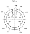
embodiment 1 of the present invention. - Fig. 3 is a diagram showing a condition of an intermediate member of RF coil being segmented into a plurality of pieces and embedded in the concave of a gradient magnetic field coil.
- Fig. 4 is a schematic view showing a coil pattern of gradient magnetic field
main coil 13a in X or Y direction inembodiment 1. - Fig. 5 is a diagram showing only a cross section of the upper side part of a horizontal magnetic field type MRI apparatus of short bore relating to
embodiment 2. - Fig. 6 is a diagram showing only a cross section of the upper side part of a horizontal magnetic field type MRI apparatus relating to
embodiment 3. - Fig. 7 is a diagram showing only a cross section of the upper side part of a horizontal magnetic field type MRI apparatus relating to
embodiment 4. - Fig. 8 is a diagram showing a cross section of a vertical magnetic field type MRI apparatus relating to
embodiment 5. - Hereinafter, system configuration of an MRI apparatus will be described in detail.
Configuration of an MRI apparatus can be classified broadly into central processing unit (hereinafter referred to as CPU) 1,sequencer 2,transmission system 3, static magneticfield generation magnet 4,reception system 5, gradient magneticfield generation system 21, andsignal processing system 6. -
CPU 1controls sequencer 2,transmission system 3,reception system 5 andsignal processing system 6 according to the program set in advance. Sequencer 2 operates based on the control command fromCPU 1, and is caused to transmit a variety of commands necessary for collecting image data of fault planes of examinee 7 totransmission system 3, gradient magneticfield generation system 21 andreception system 5. - The
transmission system 3 comprises devices such as high-frequency oscillator 8, modulator 9,irradiation coil 11 and RF shield, and irradiates predetermined pulsing electromagnetic waves to the examinee by performing amplitude modulation on the reference high-frequency pulse from high-frequency oscillator 8 by modulator 9, amplifying the amplitude modulated high-frequency pulse via high-frequency amplifier 10 and providing them toirradiation coil 11. - Static
magnetic field magnet 4 is for generating a homogeneous static magnetic field around examinee 7 in a predetermined direction.Irradiation coil 11, gradientmagnetic field coil 13 andreception coil 14 are disposed inside of the staticmagnetic field magnet 4. Gradientmagnetic field coil 13 is included in gradient magneticfield generation system 21, receives provision of electric current from gradient magneticfield power source 12, and causes to generate gradient magnetic field under the control ofsequencer 2. -
Reception system 5 is for detecting high-frequency signals (NMR signals) discharged by nuclear magnetic resonance of atomic nuclei of biochemical tissue of the examinee, havingreception coil 14,amplifier 15,quadrature detector 16 and A/D converter 17. High-frequency signals (NMR signals) responded from the examinee by electromagnetic waves irradiated from above-mentionedirradiation coil 11 are detected byreception coil 14 arranged in contiguity with the examinee, inputted to A/D converter 17 viaamplifier 15 andquadrature detector 16, converted into digital quantity, and transmitted toCPU 1. -
Signal processing system 6 comprises an external storage such asmagnetic disk 20 andoptical disk 19 and display 18 having a device such as CRT. When data fromreception system 5 is inputted toCPU 1,CPU 1 executes processes such as signal processing or image reconstruction, displays images of the desired cross sections of examinee 7 which are the result of the previously mentioned processes ondisplay 18, and stores the images to a device such asmagnetic disk 20 of the external storage. - Fig. 2 is a diagram showing a cross section of a horizontal magnetic field type MRI apparatus (tunnel type) relating to
embodiment 1 of the present invention. In Fig. 2, 4 is a static magnetic field generation magnet, and is for generating static magnetic field having high uniformity in the center ofimaging space 202 by arranging a plurality of concentric superconducting coils as having Z-axis 201 in horizontal direction. Static magneticfield generation magnet 4 comprisesvacuum case 4a forming a donut shape,helium container 4b disposed invacuum case 4a, coils such asmain coil 4c,uniformity controlling coil 4d andshielding coil 4e arranged inhelium container 4b.Main coil 4c is for generating main static magnetic field toimaging space 202,uniformity controlling coil 4d is for improving uniformity of static magnetic field generated bymain coil 4c, andshielding coil 4e is for restraining the magnetic field from leaking to the outside of the gantry. Also, though not shown in the diagram, a heat shield is provided on the outside ofhelium container 4b invacuum case 4a, and a cooing machine is provided to re-condense the liquid helium evaporated in the helium container. - Also in Fig. 2, 13 is a gradient magnetic field coil, and is formed by components such as gradient magnetic field
main coil 13a for generating main gradient magnetic field toimaging space 202, gradient magneticfield shielding coil 13b arranged on the side of static magneticfield generation magnet 4 of gradient magnetic fieldmain coil 13a and is for preventing unnecessary eddy current to be carried tovacuum case 4 and other parts forming static magneticfield generation magnet 4 due to the leakage of magnetic field generated by gradient magnetic fieldmain coil 13a which causes negative effect, andintermediate member 13c for maintaining the spacing between gradient magnetic fieldmain coil 13a and gradient magneticfield shielding coil 13b. - Further, gradient magnetic field
main coil 13a in the present embodiment is formed bybottom potion 13d,coupling potion 13e andedge portion 13f, and the central portion (bottom portion 13d) nearimaging space 202 is depressed toward the side of static magneticfield generation magnet 4. In the depressed portion,irradiation coil 11, andRF shield 11a which is imposed in the back surface ofirradiation coil 11 and is for preventing negative effects caused by electromagnetic waves generated byirradiation coil 11 interfering with parts such as gradientmagnetic field coil 13, are completely contained. - In the present embodiment,
irradiation coil 11 is formed by components such as electric conductor, to be the current path, and capacitor elements. Also,RF shield 11a is formed by a board for shielding high-frequency radiation, and irradiation coil and RF shield are mechanically connected by an intermediate member for the irradiation coil (not shown in the diagram). Generally the intermediate member for the irradiation coil has 10∼15mm thickness.
In order to completely containirradiation coil 11,RF shield 11a or the intermediate member for irradiation coil in the concave portion of gradient magnetic fieldmain coil 13a, measures are taken to, for example, segment each of them by 180 degrees, arrange them in predetermined positions and connect necessary parts. Or, manufacturing method measures can also be taken by piling up the gradient magnetic field coils around the irradiation coil that is manufactured first. - Also, as shown in Fig. 3, the intermediate member for the irradiation coil may segmented into a plurality of pieces (301 ∼ 305) and embedded in the concave of the gradient magnetic field coil. In such configuration shown in Fig. 3, a flexible substrate by which a part of a circuit is cut and made into a planar form (foldable) is used for the body of the irradiation coil with the attachments such as a condenser or inductor (301a ∼ 305a). A circuit can be configured through attaching the body of irradiation coil to the intermediate member and connecting the cut section by a technique such as soldering. Also, an RF shield is generally flexible, formed by a material such as copper foil or copper mesh, and is configured to attach the cut portion of the material to areas such as the inner periphery surface of the gradient magnetic coil or the outer periphery surface of the intermediate member for irradiation coil (for example, 301b ∼ 305b).
- More concrete description on the configuration of gradient magnetic field
main coil 13a and gradient magneticfield shielding coil 13b referring to Fig. 2 is as follows. Imagingspace 202 side ofvacuum case 4a basically forms a cylinder shape, and gradient magneticfield shielding coil 13b forms a cylinder shape along with previously mentioned cylinder shape and has a predetermined internal radius (hereinafter referred to as A). Further, gradient magnetic fieldmain coil 13a is formed by cylinder shape conductor parts (13d and 13f) having internal radius B or C which is smaller than the internal radius A, andcoupling portion 13e for connecting those parts. Here, a part having internal radius C is imposed more on the outside than the part having internal radius B with respect toimaging space 202 in Z-axis 201 direction, and internal radius C is made smaller than internal radius B. - Generally in MRI system, the whole magnet is covered by a gantry cover. In this case, the radius of the internal periphery surface of the gantry cover of the side facing imaging space 202 (distance shown by RG in Fig. 2) is an important value for defining the open construction of the gantry.
- In the present embodiment of the horizontal magnetic field type MRI apparatus, gradient magnetic field
main coil 13a is formed bybottom portion 13d positioned nearimaging space 202 in Z-axis 201 direction,edge portion 13f positioned far from imaging space 32, andcoupling portion 13e for connectingbottom portion 13d andedge portion 13f, andbottom portion 13d is imposed to a position closer to static magneticfield generation magnet 4 compared toedge portion 13f (position distant from Z-axis 201). - With this configuration,
irradiation coil 11 andRF shielding coil 11a can be contained in the cylindershape conductor part 13d having a large radius. As a result, the spacing between the surface ofimaging space 202 side of static magneticfield generation magnet 4 and thesurface 203 ofimaging space 202 side of the gantry cover (distance shown by TG in Fig. 2) can be narrowed, compared to the conventional case that both gradient magnetic fieldmain coil 13a and gradient magneticfield shielding coil 13b are flat plate. In other words, if the internal periphery surface of static magnetic field generation magnet 4 (TG+ RG) is the same size, TG can be narrowed only by the thickness portion ofirradiation coil 11 andRF shielding coil 11a. As a result, since bore radius (distance shown by RG in Fig. 2) can be extended, opened construction of the MRI apparatus can be improved. - Also, if the size of RG is to set as the same size of a conventional apparatus, coils 4c and 4d in static magnetic
field generation magnet 4 can be imposed closer toimaging space 202 side by the portion that TG is narrowed. In other words, since radius d can be made smaller, static magnetic field with stronger intensity can be generated with the same degree of current value as the conventional apparatus. Conversely, if intensity of the static magnetic field is about the same, less current value is required to be applied. - Furthermore, shaft length (L) of static magnetic
field generation magnet 4 can be shortened. Generally, the smaller the prospective angle formed by the superconducting coil and z-axis 201 as seen from the center of uniformmagnetic field region 202 is made, the easier it is to generate favorable magnetic field homogeneity. Therefore, when magnetic homogeneity is kept constant, the smaller the coil radius d is made, the more axis length L of the coil can be shortened until the above-mentioned prospective angle reaches to a predetermined angle. As a result, the axis length of the gantry can be shortened, whereby enabling improvement of the opened construction of the apparatus. For example, when size of the coil is L = 1m and 2d = 1m, L can be shortened about 5cm by making 2d 5cm shorter. In view of this, such configuration of gradientmagnetic field coil 13 in the present embodiment is especially effective in a horizontal magnetic field type MRI apparatus having a short bore (e.g. axis length (L) of 1300mm and below) with which the axis length (the length shown by L in Fig. 2) is shortened and the opened construction is improved. In addition, while couplingportion 13e in Fig. 2 is illustrated to have a surface vertical to Z-axis 201, it may be tapered as need arises. - In the present embodiment, since the distance between
irradiation coil 11 andRF shielding coil 11a can be set as about the same as the conventional apparatuses, magnetic field generation efficiency ofirradiation coil 11 can be sufficiently improved. Also, in regard to the gradient magnetic field coil, since the internal radius ofcylindrical conductor portion 13f is normally smaller with respect to endportion 13f in the outside of Z-axis 31 direction having higher density thanbottom portion 13d on the inside of Z-axis 201 direction nearimaging space 202, negative influence over gradient magnetic field generation efficiency can be reduced. - Fig. 4 is a schematic view showing a coil pattern of gradient magnetic field
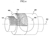
main coil 13a for X or Y-direction in the present embodiment. Coil pattern is formed vorticosely, and the current density is high in the outside of Z-axis direction apart from imaging space 202 (in other words, the spacing between adjacent conducting wires of the coil pattern is short). In the present embodiment, as seen in Fig. 4, gradient magnetic fieldmain coil 13 is configured that the coil is attached on the outside of container-like obj ect 401 by which cylinders with different radii are combined. In the example of Fig. 4, magnetic field generation efficiency of gradientmagnetic field coil 13 is made higher through making the size ofend portion 13f as large as possible by arranging the central portion of the vorticose coil pattern in the vicinity ofportion 402 being a bump due to combining the cylinders with different radius. In this regard, however, the portion being a bump does not have to be the center of the vorticose coil pattern. When the bump portion is apart from the center of the vorticose coil pattern, there is an advantage in improving the characteristic of the generated gradient magnetic field since the number of coils attached to the bump portion is reduced, or in facilitating the manufacture since the number of conducting wires for connectingcylindrical conductor portions - Fig. 5 is a diagram showing only a cross section of an upper part of a horizontal magnetic field type MRI apparatus having a short bore relating to
embodiment 2 of the present invention. In the present embodiment, out of the parts such asirradiation coil 11 andRF shield 11a that are configuringtransmission system 3, external diameter (D) ofcylindrical irradiation coil 11 is smaller than internal diameter (C) ofcylindrical conductor portion 13f. As a result, onlyirradiation coil 11 is protruded from the concave of gradient magnetic fieldmain coil 13a. To solve this problem,irradiation coil 11 can be easily disposed by sliding along gradient magnetic fieldmain coil 13a from the outside of axis-direction of the gantry, though the improvement effect of the opened construction of the MRI apparatus is slightly reduced. The present embodiment has the advantage besides the one ofembodiment 1 of improving the magnetic field generation efficacy by gradientmagnetic field coil 13, since the spacing between gradient magnetic fieldmain coil 13a and gradient magneticfield shielding coil 13b can be broadened compared toembodiment 1. Also, whileintermediate member 13c is used to join gradient magnetic fieldmain coil 13a and gradient magneticfield shielding coil 13b maintaining a predetermined spacing, it is possible to arrange in the inside ofintermediate member 13c a shim coil, passive shim formed by material such as iron, or pipes for absorbing heat generated from gradientmagnetic field coil 13. - Fig. 6 is a diagram showing only a cross section of the upper part of the horizontal magnetic field type MRI apparatus relating to
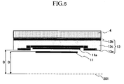
embodiment 3 of the present invention. In an example of the present embodiment, compared toembodiment 2, the surface inend 601 ofintermediate member 13c for joining gradient magnetic fieldmain coil 13a and gradientmagnetic shielding coil 13b is tapered, and width ofintermediate member 13c is made narrower on the side ofimaging space 202 than the side ofmagnet 4, in Z-axis 201 direction. By this configuration, the end portion ofgantry cover 602 covering the whole magnet can be formed having a certain curvature. As a result, the opened construction of the MRI apparatus can be further improved in addition to the improvements described inembodiments - Fig. 7 is a diagram showing only a cross section of the upper part of a horizontal magnetic field type MRI apparatus relating to
embodiment 4 of the present invention. In the present embodiment, compared toembodiment 3, gradient magnetic fieldmain coil 13a and gradientmagnetic shielding coil 13b are continually joined on the outside of Z-axis 201 direction ofintermediate member 13c.
As described inJP-A-H8-38457 embodiments 1 ∼ 3, the advantage of reducing the variable magnetic field with respect to the examinee is further attained by the present configuration, due to the acquisition of the effect of constraining the gradient magnetic field in the outside of the imaging region of the examinee. - Fig. 8 is a diagram showing a cross section of a vertical magnetic field type MRI apparatus (open type) relating to
embodiment 5 in the present invention. In Fig. 8, 4f indicates the static magnetic field generation magnet arranged over and under the imaging space facing each other, and other numbers are the same as shown in Fig. 2 ofembodiment 1. Difference is that the parts such as gradientmagnetic field coil 13 orirradiation coil 11 shown in Fig. 8 in the present embodiment are not the combination of cylinder shape parts as inembodiments 1 ∼ 4, but are in disk-like shape being conformed to the shape of the static magnetic field generation magnets in the vertical magnetic field type MRI apparatus (open type). In the present embodiment, the gradient magnetic field main coil is divided into an inside and outside portions with respect to the central axis of the static magnetic field, the inside is kept at a distance from imaging space (distanced toward the outside in vertical directions (up and down)), and at least a part of the irradiation coil and the like are contained therein. This configuration enables the enlargement ofimaging space 202 for placing the examinee, whereby improving the open construction of the MRI apparatus. - The present invention is not limited to the above-mentioned embodiments, and various changes may be made without departing from the scope of the invention. For example, while the radius of gradient magnetic field
main coil 13a is configured bycylindrical bottom portion 13d andend portion 13f formed by two kinds of internal radii, the kind of radius for the cylindrical shape with different size of internal radii may be more than 3 kinds. Also, inembodiment 5, the number for dividing the gradient magnetic field main coil with respect to the central axis is not limited to two (inside and outside), and may be more than 3. Also, technical features described inembodiments 1~4 can be applied to the vertical magnetic field type MRI apparatus illustrated inembodiment 5. The direction for disposingcoupling portion 13e in Fig. 2 may be vertical to Z-axis as seen in Fig. 6, or it may be tilted as seen in Fig. 7. Also, it goes without saying that while the body axis of the examinee placed in the imaging space is Z-axis 201 in the horizontal magnetic field type MRI apparatus ofembodiments 1 ∼ 4, it is a horizontal direction vertical to Z-axis 201 in the vertical magnetic field type MRI apparatus inembodiment 5.
Claims (17)
- A magnetic resonance imaging apparatus comprising:static magnetic field generation means arranged in the vicinity of an imaging space where an examinee is to be located, and generating a static magnetic field in the imaging space;gradient magnetic field generation means arranged in the imaging space side of the static magnetic field generation means and generating a gradient magnetic field in the imaging space; andhigh-frequency magnetic field generation means arranged at the imaging space side of the gradient magnetic field generation means and generating a high-frequency magnetic field in the imaging space,wherein the gradient magnetic field generation means has a concave portion in the vicinity of the imaging space depressed toward the static magnetic field generation means, and at least a part of the high-frequency magnetic field generation means is contained in the concave portion.
- The magnetic resonance imaging apparatus according to claim 1, wherein the concave portion has a cross section shaped in rectangle, and one side of the rectangle is parallel to the body axis of an examinee located in the imaging space.
- The magnetic resonance imaging apparatus according to claim 1, wherein the concave portion has a trapezoidal shape, and the upper and lower hem of the trapezoid are parallel to the body axis of the examinee located in the imaging space.
- The magnetic resonance imaging apparatus according to claims 1 ∼ 3, wherein:the static magnetic field generation means has a cylindrical shape;the gradient magnetic field generation means is placed along the internal surface of the cylinder on the imaging space side of the static magnetic field generation means; andthe concave portion is formed along the internal surface of the cylinder.
- The magnetic resonance imaging apparatus according to claims 1 ∼ 4, wherein:the gradient magnetic field generation means has a gradient magnetic field main coil for generating a main gradient magnetic field in the imaging space, and a gradient magnetic field shielding coil for preventing the magnetic field generated by the gradient magnetic field main coil from leaking to the other side of the imaging space;the gradient magnetic field main coil is formed by a first cylindrical portion having a first radius which has the same axis as the body axis of the examinee, a second cylindrical portion which has the smaller internal radius than the first internal radius and the same axis as the body axis of the examinee, and a coupling portion for connecting the first cylindrical portion and the second cylindrical portion; andthe first cylindrical portion is placed on the side closer to the imaging space than the second cylindrical portion along the body axis direction of the examinee, and the high-frequency magnetic field generation means is placed on the imaging space side of the first cylindrical portion.
- The magnetic resonance imaging apparatus according to claim 5, wherein the second cylindrical portion and the coupling portion are divided into two directions which are in one direction and the other direction with respect to the first cylindrical portion in the body axis direction of the examinee, and each of them are symmetrically imposed in one direction and the other direction with respect to the center of the imaging space in the body axis direction of the examinee.
- The magnetic resonance imaging apparatus according to claims 1 ∼ 3, wherein:the static magnetic field generation means are arranged facing each other sandwiching an imaging space therebetween;the gradient magnetic field generation means are arranged facing each other sandwiching the imaging space therebetween on the imaging side of the static magnetic field generation means; andthe concave portion is formed in disk-like shape along the above-mentioned surfaces facing each other.
- The magnetic resonance imaging apparatus according to claim 7, wherein:the gradient magnetic field generation means is formed by a gradient magnetic field main coil for generating a main gradient magnetic field in the imaging space, and a gradient magnetic field shielding coil for preventing the magnetic field generated by the gradient magnetic field main coil from leaking to the other side of the imaging space;the gradient magnetic field main coil is formed by the inside portion and outside portion with respect to the central axis of the static magnetic field, and the coupling portion for connecting the inside and outside portions; andthe inside portion is imposed more on the outside with respect to the imaging space in opposed directions than the outside portions, and the high-frequency magnetic field generation means is disposed on the imaging space side of the inside portion.
- The magnetic resonance imaging apparatus according to claims 5,6 and 8 wherein:the spacing between the gradient magnetic field main coil and the gradient magnetic field shielding coil is provided with an intermediate member for maintaining the spacing with predetermined intervals;the gradient magnetic field main coil is narrower in width than the gradient magnetic field shielding coil in the body axis direction of the examinee; andthe most outside surface of the intermediate member in the body axis direction of the examinee is tilted with respect to the direction vertical to the body axis of the examinee while connecting the outside edges in the body axis direction of the gradient magnetic field main coil and the.gradient magnetic field shielding coil having different length.
- The magnetic resonance imaging apparatus according to claims 1 ∼ 9, wherein:high-frequency magnetic field generation means is formed in 2 layers, of which one layer is arranged on the imaging space side and is an RF coil formed by a conductor or condenser element, and the other layer is an RF shield arranged on the gradient magnetic field generation means side; andthe RF coil and RF shield are maintained at predetermined intervals by an intermediate member for the high-frequency magnetic field generation means.
- The magnetic resonance imaging apparatus according to claim 10, wherein the RF coil is arranged on the outside of the concave portion, and is enabled to be imposed by sliding it to the body axis direction of the examinee.
- The magnetic resonance imaging apparatus according to claims 5, 6, 8 ∼ 11, wherein the gradient magnetic field main coil and the gradient magnetic field shielding coil are imposed by being continually connected at surfaces on the most outer side of the intermediate member in the body axis direction of the examinee
- The magnetic resonance imaging apparatus according to claims 10 ~ 12, wherein the RF coil, RF shield and intermediate member for high-frequency magnetic field generation means are segmented and contained in the concave portion.
- The magnetic resonance imaging apparatus according to claims 5, 6, 8 ∼ 13, wherein the gradient magnetic field main coil is configured such that a coil is attached to a container having a bump made by combining the cylinders having different size of radii.
- The magnetic resonance imaging apparatus according to claim 14, characterized in that the center of coil pattern of the coil is placed in the vicinity of the bump.
- The magnetic resonance imaging apparatus according to claims 5, 6, 8 ~ 15, wherein the coupling portion is vertically excited in the body axis direction with respect to the examinee.
- The magnetic resonance imaging apparatus according to claims 5, 6, 8~15 wherein the coupling portion is tilted with respect to the direction vertical to the body axis of the examinee.
Applications Claiming Priority (2)
| Application Number | Priority Date | Filing Date | Title |
|---|---|---|---|
| JP2004343660 | 2004-11-29 | ||
| PCT/JP2005/021835 WO2006057395A1 (en) | 2004-11-29 | 2005-11-29 | Magnetic resonance imaging device |
Publications (2)
| Publication Number | Publication Date |
|---|---|
| EP1820445A1 true EP1820445A1 (en) | 2007-08-22 |
| EP1820445A4 EP1820445A4 (en) | 2010-06-23 |
Family
ID=36498128
Family Applications (1)
| Application Number | Title | Priority Date | Filing Date |
|---|---|---|---|
| EP05811706A Withdrawn EP1820445A4 (en) | 2004-11-29 | 2005-11-29 | MAGNETIC RESONANCE IMAGING DEVICE |
Country Status (4)
| Country | Link |
|---|---|
| US (1) | US7605587B2 (en) |
| EP (1) | EP1820445A4 (en) |
| JP (1) | JP4897493B2 (en) |
| WO (1) | WO2006057395A1 (en) |
Cited By (3)
| Publication number | Priority date | Publication date | Assignee | Title |
|---|---|---|---|---|
| WO2008053451A1 (en) * | 2006-11-03 | 2008-05-08 | Koninklijke Philips Electronics N.V. | Split gradient coil for mri |
| WO2010064197A1 (en) * | 2008-12-04 | 2010-06-10 | Koninklijke Philips Electronics N.V. | Magnetic resonance imaging system with satellite gradient coils |
| CN102903473A (en) * | 2011-07-29 | 2013-01-30 | 通用电气公司 | Superconducting magnet system |
Families Citing this family (7)
| Publication number | Priority date | Publication date | Assignee | Title |
|---|---|---|---|---|
| US7852083B2 (en) * | 2006-04-14 | 2010-12-14 | Hitachi Medical Corporation | Magnetic resonance imaging apparatus and gradient magnetic field coil |
| JP4980693B2 (en) * | 2006-11-10 | 2012-07-18 | 株式会社日立メディコ | Magnetic resonance imaging apparatus and RF irradiation coil |
| DE102007054592B4 (en) * | 2007-11-15 | 2014-04-30 | Siemens Aktiengesellschaft | Plug connection device, designed to connect two functional elements for signal and power transmission |
| US8169220B2 (en) * | 2009-12-15 | 2012-05-01 | General Electric Company | Flattened gradient coil for MRI systems |
| EP3497459B1 (en) | 2016-08-15 | 2024-11-20 | Koninklijke Philips N.V. | Actively shielded gradient coil assembly for a magnetic resonance examination system |
| CN108646205A (en) * | 2018-04-17 | 2018-10-12 | 杭州佩伟拓超导磁体技术有限公司 | Open MRI miniature imaging system magnet structure |
| ES2986587T3 (en) * | 2018-12-13 | 2024-11-12 | Magnetica Ltd | Gradient coil system |
Family Cites Families (19)
| Publication number | Priority date | Publication date | Assignee | Title |
|---|---|---|---|---|
| JPS631008A (en) | 1986-06-20 | 1988-01-06 | Fuji Electric Co Ltd | Uniform field coil for nuclear magnetic resonance type tomograph |
| JPH03210236A (en) | 1990-01-16 | 1991-09-13 | Hitachi Medical Corp | Magnetic resonance imaging device |
| DE4230145C2 (en) * | 1992-09-09 | 1996-09-05 | Bruker Analytische Messtechnik | NMR measuring device |
| US5561371A (en) | 1995-09-27 | 1996-10-01 | General Electric Company | Transverse gradient coil |
| US5638595A (en) | 1995-11-09 | 1997-06-17 | General Electric Company | Method for fabricating open MR magnet gradient coil |
| JP3794109B2 (en) * | 1997-05-29 | 2006-07-05 | 株式会社日立メディコ | Static magnetic field generator |
| JP2000166896A (en) | 1998-12-10 | 2000-06-20 | Ge Yokogawa Medical Systems Ltd | RF coil and magnetic resonance imaging apparatus |
| DE10056807A1 (en) * | 2000-11-16 | 2002-05-23 | Philips Corp Intellectual Pty | HF planar resonator for transmitting/receiving circularly polarized electromagnetic waves has conductor structures stretching from a central area in radial directions and a conductor loop around this area for a return current. |
| JP2002253532A (en) * | 2000-12-21 | 2002-09-10 | Siemens Ag | Magnetic resonance equipment |
| JP2003164432A (en) | 2001-11-26 | 2003-06-10 | Ge Medical Systems Global Technology Co Llc | Mri device |
| DE10202986A1 (en) | 2002-01-26 | 2003-07-31 | Philips Intellectual Property | Coil system for an MR apparatus and MR apparatus with such a coil system |
| GB0223684D0 (en) * | 2002-10-10 | 2002-11-20 | Tesla Engineering Ltd | Gradient coil structure for magnetic resonace imaging |
| GB2400671B (en) * | 2003-02-12 | 2006-05-10 | Siemens Ag | Magnetic resonance apparatus with a coil arrangement and an electrically conducting structure |
| CN100507593C (en) * | 2003-03-25 | 2009-07-01 | 西门子公司 | Magnetic field generator and magnetic resonance equipment with the magnetic field generator |
| DE10346275B4 (en) * | 2003-10-06 | 2005-08-18 | Siemens Ag | Producer of time-variable magnetic fields of a magnetic resonance apparatus and magnetic resonance apparatus with the producer |
| DE10354228B3 (en) * | 2003-11-20 | 2005-09-22 | Siemens Ag | A gradient coil radio frequency antenna unit and a magnetic resonance apparatus having a gradient coil radio frequency antenna unit |
| DE102005058651B4 (en) * | 2005-01-26 | 2012-02-16 | Siemens Ag | Magnetic resonance device and integrated gradient and radio frequency coil unit |
| DE102005013853B4 (en) * | 2005-03-24 | 2009-06-25 | Siemens Ag | Magnetic resonance system with a high-frequency transmitting antenna |
| US7375526B2 (en) * | 2006-10-20 | 2008-05-20 | Edelstein William A | Active-passive electromagnetic shielding to reduce MRI acoustic noise |
-
2005
- 2005-11-29 EP EP05811706A patent/EP1820445A4/en not_active Withdrawn
- 2005-11-29 JP JP2006547923A patent/JP4897493B2/en not_active Expired - Fee Related
- 2005-11-29 US US11/791,878 patent/US7605587B2/en not_active Expired - Fee Related
- 2005-11-29 WO PCT/JP2005/021835 patent/WO2006057395A1/en not_active Ceased
Cited By (6)
| Publication number | Priority date | Publication date | Assignee | Title |
|---|---|---|---|---|
| WO2008053451A1 (en) * | 2006-11-03 | 2008-05-08 | Koninklijke Philips Electronics N.V. | Split gradient coil for mri |
| WO2010064197A1 (en) * | 2008-12-04 | 2010-06-10 | Koninklijke Philips Electronics N.V. | Magnetic resonance imaging system with satellite gradient coils |
| US9435869B2 (en) | 2008-12-04 | 2016-09-06 | Koninklijke Philips N.V. | Magnetic resonance imaging system with satellite gradient coils |
| CN102903473A (en) * | 2011-07-29 | 2013-01-30 | 通用电气公司 | Superconducting magnet system |
| US8914086B2 (en) | 2011-07-29 | 2014-12-16 | General Electric Company | Superconducting magnet system |
| CN102903473B (en) * | 2011-07-29 | 2016-03-30 | 通用电气公司 | superconducting magnet system |
Also Published As
| Publication number | Publication date |
|---|---|
| JP4897493B2 (en) | 2012-03-14 |
| US7605587B2 (en) | 2009-10-20 |
| US20080061787A1 (en) | 2008-03-13 |
| WO2006057395A1 (en) | 2006-06-01 |
| JPWO2006057395A1 (en) | 2008-06-05 |
| EP1820445A4 (en) | 2010-06-23 |
Similar Documents
| Publication | Publication Date | Title |
|---|---|---|
| US8089281B2 (en) | Doubly resonant high field radio frequency surface coils for magnetic resonance | |
| US20100176811A1 (en) | Open magnetic resonance imaging apparatus | |
| JP5670503B2 (en) | Magnetic resonance imaging apparatus and gradient coil | |
| US20100127707A1 (en) | Wearable magnetic resonator for mri resolution improvement, and application device including the same | |
| US7605587B2 (en) | Magnetic resonance imaging apparatus | |
| JP2011087904A (en) | Magnetic resonance imaging apparatus | |
| US8466681B2 (en) | Open-type MRI apparatus, and open-type superconducting MRI apparatus | |
| US7576540B2 (en) | Gradient coil and magnetic resonance imaging apparatus using the same | |
| WO2008075614A1 (en) | Nuclear magnetic resonance measuring device and coil unit | |
| KR101551586B1 (en) | Coil device and magnetic resonance imagining equipment | |
| US8928450B2 (en) | Transformer assembly for a magnetic resonance imaging system | |
| JP7050753B2 (en) | Active Shield Gradient Coil Assembly for Magnetic Resonance Inspection Systems | |
| US20110304422A1 (en) | Transformer assembly for a magnetic resonance imaging system | |
| US7898257B2 (en) | Open yoke magnet assembly | |
| US20150042342A1 (en) | Shielding with Integrated Cooling | |
| JP5069471B2 (en) | Planar RF resonator for open MRI systems | |
| JP6334444B2 (en) | Magnetic resonance imaging system | |
| US10466320B2 (en) | Multi-layered radio frequency coil | |
| CN115245323B (en) | Periodic structures and magnetic resonance imaging devices | |
| JP2002052006A (en) | High frequency coil for nuclear magnetic resonance imaging apparatus and nuclear magnetic resonance imaging apparatus | |
| CN116893376A (en) | Array coil and manufacturing method | |
| JPH07255700A (en) | Rf coil for mri | |
| CN109922647A (en) | It is electromagnetically shielded protective shell, probe assembly and detector | |
| JPH0866379A (en) | Mri magnet and manufacture thereof | |
| JP2009172072A (en) | Magnetic resonance imaging system |
Legal Events
| Date | Code | Title | Description |
|---|---|---|---|
| PUAI | Public reference made under article 153(3) epc to a published international application that has entered the european phase |
Free format text: ORIGINAL CODE: 0009012 |
|
| 17P | Request for examination filed |
Effective date: 20070626 |
|
| AK | Designated contracting states |
Kind code of ref document: A1 Designated state(s): DE FR GB IT NL |
|
| RBV | Designated contracting states (corrected) |
Designated state(s): DE FR GB IT NL |
|
| DAX | Request for extension of the european patent (deleted) | ||
| A4 | Supplementary search report drawn up and despatched |
Effective date: 20100525 |
|
| RIC1 | Information provided on ipc code assigned before grant |
Ipc: G01R 33/385 20060101ALI20100518BHEP Ipc: G01R 33/38 20060101ALN20100518BHEP Ipc: G01R 33/422 20060101ALN20100518BHEP Ipc: G01R 33/381 20060101ALN20100518BHEP Ipc: A61B 5/055 20060101AFI20060606BHEP Ipc: G01R 33/421 20060101ALN20100518BHEP |
|
| 17Q | First examination report despatched |
Effective date: 20100607 |
|
| STAA | Information on the status of an ep patent application or granted ep patent |
Free format text: STATUS: THE APPLICATION IS DEEMED TO BE WITHDRAWN |
|
| 18D | Application deemed to be withdrawn |
Effective date: 20101019 |