EP1820427A1 - Hot and cold beverage maker - Google Patents
Hot and cold beverage maker Download PDFInfo
- Publication number
- EP1820427A1 EP1820427A1 EP07250652A EP07250652A EP1820427A1 EP 1820427 A1 EP1820427 A1 EP 1820427A1 EP 07250652 A EP07250652 A EP 07250652A EP 07250652 A EP07250652 A EP 07250652A EP 1820427 A1 EP1820427 A1 EP 1820427A1
- Authority
- EP
- European Patent Office
- Prior art keywords
- beverage
- jug
- motor
- water heater
- beverage maker
- Prior art date
- Legal status (The legal status is an assumption and is not a legal conclusion. Google has not performed a legal analysis and makes no representation as to the accuracy of the status listed.)
- Granted
Links
Images


Classifications
-
- A—HUMAN NECESSITIES
- A47—FURNITURE; DOMESTIC ARTICLES OR APPLIANCES; COFFEE MILLS; SPICE MILLS; SUCTION CLEANERS IN GENERAL
- A47J—KITCHEN EQUIPMENT; COFFEE MILLS; SPICE MILLS; APPARATUS FOR MAKING BEVERAGES
- A47J31/00—Apparatus for making beverages
- A47J31/04—Coffee-making apparatus with rising pipes
- A47J31/057—Coffee-making apparatus with rising pipes with water container separated from beverage container, the hot water passing the filter only once i.e. classical type of drip coffee makers
-
- A—HUMAN NECESSITIES
- A47—FURNITURE; DOMESTIC ARTICLES OR APPLIANCES; COFFEE MILLS; SPICE MILLS; SUCTION CLEANERS IN GENERAL
- A47J—KITCHEN EQUIPMENT; COFFEE MILLS; SPICE MILLS; APPARATUS FOR MAKING BEVERAGES
- A47J43/00—Implements for preparing or holding food, not provided for in other groups of this subclass
- A47J43/04—Machines for domestic use not covered elsewhere, e.g. for grinding, mixing, stirring, kneading, emulsifying, whipping or beating foodstuffs, e.g. power-driven
- A47J43/046—Machines for domestic use not covered elsewhere, e.g. for grinding, mixing, stirring, kneading, emulsifying, whipping or beating foodstuffs, e.g. power-driven with tools driven from the bottom side
Definitions
- the present invention relates to beverage makers and in particular to hot and cold beverage makers.
- Partially frozen beverages often called slushies, smoothies or ice beverages, are very popular. They are usually a mixture of ice and some flavored beverage, like coffee, fruit juice, tea, chocolate etc.
- Making a partially frozen beverage sometimes requires the preparation of a hot flavored beverage, such as tea, coffee and the like, first. This requires two machines, a hot beverage maker and a blender. These machines occupy a lot of countertop space and the process of transferring the hot beverage to the blender is troublesome and can easily result in an accident.
- a hot flavored beverage such as tea, coffee and the like
- a hot and cold beverage maker for use with a beverage jug having a base with a rotary blade in the beverage jug and connected to a coupling at the base of the beverage jug, the beverage maker comprising:
- the beverage maker further comprises a beverage jug having a base with a rotary blade in the beverage jug and connected to a beverage jug coupling at the base of the beverage jug.
- the beverage maker further comprises a motor in the base of the housing for rotating the rotary coupling.
- the beverage maker further comprises a pulley and belt driving system is connected between the motor and the rotary coupling.
- the beverage maker further comprises a gear chain driving system is connected between the motor and the rotary coupling.
- the rotary coupling is directly connected to the motor.
- the beverage maker further comprises a controller programmed to energize the water heater until a hot beverage is prepared, and when the hot beverage is prepared, to activate the motor.
- the controller activates the motor by turning the motor on and off in a series of pulses.
- the controller has a timer for determining when a hot beverage is prepared.
- the controller is programmed to energize the water heater and to activate the motor independently for alternatively brewing hot beverage and blending contents f the beverage jug when the beverage jug engages the rotary coupling in the cradle.
- the beverage maker further comprises a temperature sensor on the water heater for sensing a rise in temperature of the water heater, said rise in temperature indicating that the water reservoir is empty, and a controller communicating with the temperature sensor and programmed to energize the water heater until the rise in temperature of the water heater is sensed, and in response to the rise in temperature, to turn off the water heater and thereafter to activate the motor.
- a temperature sensor on the water heater for sensing a rise in temperature of the water heater, said rise in temperature indicating that the water reservoir is empty
- a controller communicating with the temperature sensor and programmed to energize the water heater until the rise in temperature of the water heater is sensed, and in response to the rise in temperature, to turn off the water heater and thereafter to activate the motor.
- the controller activates the motor by turning the motor on and off in a series of pulses.
- the controller is programmed to delay activation of the motor after turning off the water heater.
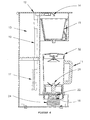
- a hot and cold beverage maker comprising a housing 10 having a lower base portion for supporting a beverage jug 11, a vertical trunk portion extending from the base and a head portion. Within the trunk portion are a water reservoir 13 and a water heater 17. A spreader 14 and brew basket 15 are located in the head portion above the beverage jug 11. The head has a pivoting lid 12 to allow the reservoir 13 to be filled. A water passage 19 is provided for delivering water from the reservoir 13 through the water heater 17 to the spreader 14 to be heated and discharged into the brew basket 15.
- An outlet in the bottom of the brew basket allows water to flow from the brew basket 15 into the jug 11 thought an inlet opening in the jug lid 32.
- This arrangement is substantially identical to known 'filter' coffee makers and its construction is within the capabilities of a person skilled in the art.
- dry beverage ingredients such as ground coffee beans, tea leaves, chocolate powder etc are placed in the brew basket 15, the reservoir 13 is filled with water and the heater 17 activated to brew hot coffee or tea, as the case may be, which fills the jug 11.
- a blender blade 21 is provide in the base of the jug 11.
- the blade 21 is located in a spindle attached to a jug drive coupling 22 beneath the base of the jug 11.
- the base of the housing is provided with a cradle for receiving the jug 11.
- the cradle has a second complementary coupling 16 mounted on a rotary spindle 31 that engages with the jug coupling 22 when the jug 11 is placed in the cradle.
- a motor 18 is located within the casing 10 and has a drive pulley 28 on its output shaft. The drive pulley is connected to a driven pulley 29 by a drive belt 23.
- the driven pulley 29 is located on the cradle spindle 31 to rotate the complementary coupling 16 when the motor is operated.
- the driven pulley 29 is located on the cradle spindle 31 to rotate the complementary coupling 16 when the motor is operated.
- the above hot and cold beverage maker can be used to make both hot beverages such as tea, coffee and chocolate or cold blended beverages such as milkshakes and smoothies.
- Figure 3 shows an embodiment of the beverage maker with a regular coffee maker jug 26 for making the former mentioned hot beverages.
- a cover plate or tray (not shown) is provided for placing over the cradle to support the regular jug 26, or even a drinking cup or mug.
- the hot and cold beverage maker can be used to make cold versions of traditionally hot beverages such as ice tea or ice coffee or ice chocolate.
- the hot beverage say coffee
- the hot beverage is made in the manner mentioned above.
- ice cubes, and if necessary sweetener are added to the jug and the motor activated to blend the contents to make an ice coffee drink.
- the preferred embodiment of the invention includes an electronic controller having an ice beverage mode for automatically perform the brew and blend functions sequentially. A correct quantity of water and coffee grounds are added to the reservoir and brew basket respectively, and ice cubes are added to the jug.
- the controller activates the water heater to brew coffee.
- a temperature sensor on the water heater senses when the temperature rises indicating that the reservoir is empty.
- the water heater is then turned off and the brew cycle ends.
- the controller then enters a blend cycle. To achieve optimum results the controller activates the motor in short pulses to blend the ice and hot beverage into ice slush. At the end of the blend cycle the controller sounds a series of beeps to indicate that the beverage is ready.
- FIG. 7 illustrates a control arrangement of the hot and cold beverage maker.
- Automated control is achieved by a machine control unit (MCU) 33 connected to various inputs and outputs.
- Inputs included three user input buttons for brew only 34, combination brew & blend 35 and blend only 36 selection and a water heater temperature sensor input 37.
- Outputs included light emitting diode (LED) indicators for brew only 38, combination brew & blend 39 and blend only 40, as well as on/off water heater control 41 and on/off motor control 42.
- LED light emitting diode
- the hot and cold beverage maker acts as a coffee maker or blender in known manner.
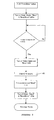
- the brew/blend button 35 is pressed the hot and cold beverage maker enters an automated cycle for making a partially frozen blended beverage. The following discussion relates to operation of this automated brew & blend cycle.
- the user first places ingredients for the beverage flavor in the brew basket 15 and fills the water reservoir 13 with water. Crushed or cubed ice is placed in the jug 11 and the jug 11 located on the base cradle.
- the user pushes the brew/blend button 35.
- the MCU 33 in response to this input, turns on the brew LED 38, the brew/blend LED 39 and the water heater 17.
- the device began brewing the flavored beverage while the MCU 33 monitors the water heater temperature via sensor input 37. When the water heater temperature rises to about 145 degrees, indicating the end of the brew cycle, the MCU 33 turns off the brew LED 38 and water heater 17.
- the brew/blend LED 39 is left on.
- the MCU 33 Before entering the blend sequence the MCU 33 enters a rest period 43 for a predetermine time, say 30 seconds. At the end of the rest period 43 the beverage and ice in the jug 11 are blended by the MCU 33 turning on the blend LED 40 and pulsing the motor 18 on and off. At the end of the blend sequence the motor 18, blend LED 40 and brew/blend LED 39 are turned off. The automatic cycle is finished.
- Figures 5 and 6 illustrate embodiments of the beverage maker that use alternative means to drive the blending blade.
- the embodiment in Figure 5 uses a gear configuration. Rather than pulleys 28, 29 and belt 23 a series of gears 25 are used to transfer rotation of motor shaft 30 to coupling spindle 31.
- the embodiment in Figure 6 has a motor arranged beneath the cradle with the driven coupling located directly on the motor shaft.
Abstract
Description
- The present invention relates to beverage makers and in particular to hot and cold beverage makers.
- Partially frozen beverages, often called slushies, smoothies or ice beverages, are very popular. They are usually a mixture of ice and some flavored beverage, like coffee, fruit juice, tea, chocolate etc.
- Making a partially frozen beverage sometimes requires the preparation of a hot flavored beverage, such as tea, coffee and the like, first. This requires two machines, a hot beverage maker and a blender. These machines occupy a lot of countertop space and the process of transferring the hot beverage to the blender is troublesome and can easily result in an accident.
- It is an object of the present invention to overcome or substantially ameliorate the above disadvantage and/or more generally to provide a hot and cold beverage maker that can be used to make both hot beverages and cold blended beverages, and more particularly to make cold versions of traditionally hot beverages such as ice tea, ice coffee or ice chocolate.
- There is disclosed herein a hot and cold beverage maker for use with a beverage jug having a base with a rotary blade in the beverage jug and connected to a coupling at the base of the beverage jug, the beverage maker comprising:
- a housing having a base and an upper body,
- a water reservoir in the housing,
- a brew basket in the upper body having a water outlet for discharge of a brewed beverage,
- a water heater,
- a water passage from the reservoir through the water heater to the brew basket for delivering heated water to the brew basket,
- a cradle on the base of the housing for supporting a beverage jug beneath the brew basket outlet, and
- a rotary coupling in the cradle for engaging a corresponding coupling of a beverage jug placed in the cradle.
- Preferably, the beverage maker further comprises a beverage jug having a base with a rotary blade in the beverage jug and connected to a beverage jug coupling at the base of the beverage jug.
- Preferably, the beverage maker further comprises a motor in the base of the housing for rotating the rotary coupling.
- Preferably, the beverage maker further comprises a pulley and belt driving system is connected between the motor and the rotary coupling.
- Preferably, the beverage maker further comprises a gear chain driving system is connected between the motor and the rotary coupling.
- Preferably, the rotary coupling is directly connected to the motor.
- Preferably, the beverage maker further comprises a controller programmed to energize the water heater until a hot beverage is prepared, and when the hot beverage is prepared, to activate the motor.
- Preferably, the controller activates the motor by turning the motor on and off in a series of pulses.
- Preferably, the controller has a timer for determining when a hot beverage is prepared.
- Preferably, the controller is programmed to energize the water heater and to activate the motor independently for alternatively brewing hot beverage and blending contents f the beverage jug when the beverage jug engages the rotary coupling in the cradle.
- Preferably, the beverage maker further comprises a temperature sensor on the water heater for sensing a rise in temperature of the water heater, said rise in temperature indicating that the water reservoir is empty, and a controller communicating with the temperature sensor and programmed to energize the water heater until the rise in temperature of the water heater is sensed, and in response to the rise in temperature, to turn off the water heater and thereafter to activate the motor.
- Preferably, the controller activates the motor by turning the motor on and off in a series of pulses.
- Preferably, the controller is programmed to delay activation of the motor after turning off the water heater.
- Further aspects of the invention will become apparent from the following description.
- A preferred form of the present invention will now be described by way of example only and with reference to the accompanying drawings, wherein:
- Figures 1 and 2 are perspective illustrations of a hot and cold beverage maker according to the invention,
- Figure 3 is a perspective illustration of an alternative embodiment of the beverage maker,
- Figure 4 is a sectional schematic illustration of the beverage maker, and
- Figures 5 and 6 are sectional schematic illustrations of alternative embodiments of the beverage maker.
- In Figures 1, 2 and 4 there is depicted a preferred embodiment of a hot and cold beverage maker comprising a
housing 10 having a lower base portion for supporting abeverage jug 11, a vertical trunk portion extending from the base and a head portion. Within the trunk portion are awater reservoir 13 and awater heater 17. Aspreader 14 andbrew basket 15 are located in the head portion above thebeverage jug 11. The head has a pivotinglid 12 to allow thereservoir 13 to be filled. Awater passage 19 is provided for delivering water from thereservoir 13 through thewater heater 17 to thespreader 14 to be heated and discharged into thebrew basket 15. An outlet in the bottom of the brew basket allows water to flow from thebrew basket 15 into thejug 11 thought an inlet opening in thejug lid 32. This arrangement is substantially identical to known 'filter' coffee makers and its construction is within the capabilities of a person skilled in the art. In use dry beverage ingredients such as ground coffee beans, tea leaves, chocolate powder etc are placed in thebrew basket 15, thereservoir 13 is filled with water and theheater 17 activated to brew hot coffee or tea, as the case may be, which fills thejug 11. - In the current device a
blender blade 21 is provide in the base of thejug 11. Theblade 21 is located in a spindle attached to ajug drive coupling 22 beneath the base of thejug 11. The base of the housing is provided with a cradle for receiving thejug 11. The cradle has a secondcomplementary coupling 16 mounted on arotary spindle 31 that engages with thejug coupling 22 when thejug 11 is placed in the cradle. Amotor 18 is located within thecasing 10 and has adrive pulley 28 on its output shaft. The drive pulley is connected to a drivenpulley 29 by adrive belt 23. The drivenpulley 29 is located on thecradle spindle 31 to rotate thecomplementary coupling 16 when the motor is operated. When thejug 11 is in the cradle of the device beverages in thejug 11 can be blended by activation of themotor 18. - The above hot and cold beverage maker can be used to make both hot beverages such as tea, coffee and chocolate or cold blended beverages such as milkshakes and smoothies. Figure 3 shows an embodiment of the beverage maker with a regular
coffee maker jug 26 for making the former mentioned hot beverages. A cover plate or tray (not shown) is provided for placing over the cradle to support theregular jug 26, or even a drinking cup or mug. - More particularly thought the hot and cold beverage maker can be used to make cold versions of traditionally hot beverages such as ice tea or ice coffee or ice chocolate. For this purpose firstly the hot beverage, say coffee, is made in the manner mentioned above. When a quantity of coffee has been brewed, ice cubes, and if necessary sweetener, are added to the jug and the motor activated to blend the contents to make an ice coffee drink. The preferred embodiment of the invention includes an electronic controller having an ice beverage mode for automatically perform the brew and blend functions sequentially. A correct quantity of water and coffee grounds are added to the reservoir and brew basket respectively, and ice cubes are added to the jug. The controller activates the water heater to brew coffee. A temperature sensor on the water heater senses when the temperature rises indicating that the reservoir is empty. The water heater is then turned off and the brew cycle ends. The controller then enters a blend cycle. To achieve optimum results the controller activates the motor in short pulses to blend the ice and hot beverage into ice slush. At the end of the blend cycle the controller sounds a series of beeps to indicate that the beverage is ready.
- Figure 7 illustrates a control arrangement of the hot and cold beverage maker. Automated control is achieved by a machine control unit (MCU) 33 connected to various inputs and outputs. Inputs included three user input buttons for brew only 34, combination brew & blend 35 and blend only 36 selection and a water heater
temperature sensor input 37. Outputs included light emitting diode (LED) indicators for brew only 38, combination brew & blend 39 and blend only 40, as well as on/offwater heater control 41 and on/offmotor control 42. - If either of the brew only 34 or blend only 36 buttons are pressed the corresponding indicator LED illuminates and the hot and cold beverage maker acts as a coffee maker or blender in known manner. When the brew/
blend button 35 is pressed the hot and cold beverage maker enters an automated cycle for making a partially frozen blended beverage. The following discussion relates to operation of this automated brew & blend cycle. - The user first places ingredients for the beverage flavor in the
brew basket 15 and fills thewater reservoir 13 with water. Crushed or cubed ice is placed in thejug 11 and thejug 11 located on the base cradle. Referring to Figure 8 the user pushes the brew/blend button 35. TheMCU 33, in response to this input, turns on thebrew LED 38, the brew/blend LED 39 and thewater heater 17. The device began brewing the flavored beverage while theMCU 33 monitors the water heater temperature viasensor input 37. When the water heater temperature rises to about 145 degrees, indicating the end of the brew cycle, theMCU 33 turns off thebrew LED 38 andwater heater 17. The brew/blend LED 39 is left on. Before entering the blend sequence theMCU 33 enters arest period 43 for a predetermine time, say 30 seconds. At the end of therest period 43 the beverage and ice in thejug 11 are blended by theMCU 33 turning on theblend LED 40 and pulsing themotor 18 on and off. At the end of the blend sequence themotor 18,blend LED 40 and brew/blend LED 39 are turned off. The automatic cycle is finished. - It should be appreciated that modifications and/or alternations obvious to those skilled in the art are not to be considered as beyond the scope of the present invention. For example, Figures 5 and 6 illustrate embodiments of the beverage maker that use alternative means to drive the blending blade.
- The embodiment in Figure 5 uses a gear configuration. Rather than
pulleys gears 25 are used to transfer rotation ofmotor shaft 30 tocoupling spindle 31. The embodiment in Figure 6 has a motor arranged beneath the cradle with the driven coupling located directly on the motor shaft.
Claims (13)
- A hot and cold beverage maker for use with a beverage jug having a base with a rotary blade in the beverage jug and connected to a coupling at the base of the beverage jug, the beverage maker comprising:a housing having a base and an upper body,a water reservoir in the housing,a brew basket in the upper body having a water outlet for discharge of a brewed beverage,a water heater,a water passage from the reservoir through the water heater to the brew basket for delivering heated water to the brew basket,a cradle on the base of the housing for supporting a beverage jug beneath the brew basket outlet, anda rotary coupling in the cradle for engaging a corresponding coupling of a beverage jug placed in the cradle.
- The beverage maker of claim 1 further comprising a beverage jug having a base with a rotary blade in the beverage jug and connected to a beverage jug coupling at the base of the beverage jug.
- The beverage maker of claim 1 or claim 2 further comprising a motor in the base of the housing for rotating the rotary coupling.
- The beverage maker of claim 3 further comprising a pulley and belt driving system is connected between the motor and the rotary coupling.
- The beverage maker of claim 3 further comprising a gear chain driving system is connected between the motor and the rotary coupling.
- The beverage maker of claim 3 wherein the rotary coupling is directly connected to the motor.
- The beverage maker of any preceding claim further comprising a controller programmed to energize the water heater until a hot beverage is prepared, and when the hot beverage is prepared, to activate the motor.
- The beverage maker of claim 7 wherein the controller activates the motor by turning the motor on and off in a series of pulses.
- The beverage maker of claim 7 or claim 8 wherein the controller has a timer for determining when a hot beverage is prepared.
- The beverage maker of any one of claims 7 to 9 wherein the controller is programmed to energize the water heater and to activate the motor independently for alternatively brewing hot beverage and blending contents f the beverage jug when the beverage jug engages the rotary coupling in the cradle.
- The beverage maker of any one of claims 1 to 6 further comprising a temperature sensor on the water heater for sensing a rise in temperature of the water heater, said rise in temperature indicating that the water reservoir is empty, and a controller communicating with the temperature sensor and programmed to energize the water heater until the rise in temperature of the water heater is sensed, and in response to the rise in temperature, to turn off the water heater and thereafter to activate the motor.
- The beverage maker of claim 11, wherein the controller activates the motor by turning the motor on and off in a series of pulses.
- The beverage maker of claim 11 or claim 12 wherein the controller is programmed to delay activation of the motor after turning off the water heater.
Applications Claiming Priority (1)
| Application Number | Priority Date | Filing Date | Title |
|---|---|---|---|
| US11/355,887 US7231142B1 (en) | 2006-02-17 | 2006-02-17 | Hot and cold beverage maker |
Publications (2)
| Publication Number | Publication Date |
|---|---|
| EP1820427A1 true EP1820427A1 (en) | 2007-08-22 |
| EP1820427B1 EP1820427B1 (en) | 2010-04-28 |
Family
ID=38024164
Family Applications (1)
| Application Number | Title | Priority Date | Filing Date |
|---|---|---|---|
| EP07250652A Not-in-force EP1820427B1 (en) | 2006-02-17 | 2007-02-16 | Hot and cold beverage maker |
Country Status (4)
| Country | Link |
|---|---|
| US (1) | US7231142B1 (en) |
| EP (1) | EP1820427B1 (en) |
| AT (1) | ATE465660T1 (en) |
| DE (1) | DE602007006072D1 (en) |
Families Citing this family (17)
| Publication number | Priority date | Publication date | Assignee | Title |
|---|---|---|---|---|
| EP2071960A1 (en) * | 2007-12-20 | 2009-06-24 | Koninklijke Philips Electronics N.V. | Method and appliance for making ice coffee |
| US7942094B2 (en) * | 2008-08-14 | 2011-05-17 | Sunbeam Products, Inc. | Frozen drink maker |
| EP2186456B1 (en) | 2008-11-06 | 2013-04-10 | Mac Design S.r.l. | Device for preparing shaken beverages |
| CN101731943B (en) * | 2008-11-27 | 2014-02-26 | Mac设计有限责任公司 | Device for preparing shake drink |
| DE202009001490U1 (en) * | 2009-02-06 | 2010-08-05 | Melitta Haushaltsprodukte Gmbh & Co. Kommanditgesellschaft | Device for dispensing drinks |
| US8613244B2 (en) * | 2009-07-10 | 2013-12-24 | IBS Interbev, Inc | Method for the production of tea beverages and other beverages |
| US8555656B2 (en) | 2010-10-28 | 2013-10-15 | Qasem A. Al-Qaffas | Thermally conductive cup and holder |
| US9370273B2 (en) | 2010-12-02 | 2016-06-21 | Pepsico, Inc. | Hot and cold beverage dispenser |
| US20140072689A1 (en) * | 2011-05-16 | 2014-03-13 | Sunbeam Products, Inc. | Hot Beverage Maker |
| US20130319034A1 (en) * | 2011-06-23 | 2013-12-05 | Sunbeam Products, Inc. | Mixed Beverage Maker |
| US9668609B2 (en) * | 2011-10-05 | 2017-06-06 | Island Oasis Frozen Cocktail Co., Inc. | Individual frozen drink dispenser |
| US9717264B2 (en) | 2011-10-05 | 2017-08-01 | Island Oasis Frozen Cocktail Co., Inc. | Individual frozen drink dispenser |
| US10455848B2 (en) | 2011-10-05 | 2019-10-29 | Island Oasis Frozen Cocktail Company, Inc. | Individual frozen drink dispenser |
| US9357874B2 (en) * | 2014-09-12 | 2016-06-07 | Andrew LICARE | Hot and cold beverage maker and method of use |
| WO2017123751A1 (en) | 2016-01-12 | 2017-07-20 | SudSense, LLC | Producing solutions from concentrates |
| CN106419554A (en) * | 2016-10-20 | 2017-02-22 | 广东辉骏科技集团有限公司 | Multifunctional automatic smoothies and coffee machine |
| US11412878B1 (en) * | 2021-11-26 | 2022-08-16 | Mark Wolf | One touch cooker |
Citations (2)
| Publication number | Priority date | Publication date | Assignee | Title |
|---|---|---|---|---|
| US5970847A (en) * | 1998-06-16 | 1999-10-26 | Saltzman; David L. | Baby formula preparation system |
| US20040237798A1 (en) * | 2002-09-30 | 2004-12-02 | Payne Ann Elizabeth | Hot mixer or steam blender |
Family Cites Families (1)
| Publication number | Priority date | Publication date | Assignee | Title |
|---|---|---|---|---|
| US20040211848A1 (en) * | 2003-04-25 | 2004-10-28 | Conair Corporation | Coffee grinder with removable bin |
-
2006
- 2006-02-17 US US11/355,887 patent/US7231142B1/en active Active
-
2007
- 2007-02-16 AT AT07250652T patent/ATE465660T1/en not_active IP Right Cessation
- 2007-02-16 EP EP07250652A patent/EP1820427B1/en not_active Not-in-force
- 2007-02-16 DE DE602007006072T patent/DE602007006072D1/en active Active
Patent Citations (2)
| Publication number | Priority date | Publication date | Assignee | Title |
|---|---|---|---|---|
| US5970847A (en) * | 1998-06-16 | 1999-10-26 | Saltzman; David L. | Baby formula preparation system |
| US20040237798A1 (en) * | 2002-09-30 | 2004-12-02 | Payne Ann Elizabeth | Hot mixer or steam blender |
Also Published As
| Publication number | Publication date |
|---|---|
| EP1820427B1 (en) | 2010-04-28 |
| ATE465660T1 (en) | 2010-05-15 |
| DE602007006072D1 (en) | 2010-06-10 |
| US7231142B1 (en) | 2007-06-12 |
Similar Documents
| Publication | Publication Date | Title |
|---|---|---|
| EP1820427B1 (en) | Hot and cold beverage maker | |
| US8286547B1 (en) | Automated french press-like quality producing, high volume, automated, electric beverage maker | |
| US5463932A (en) | Coffee maker | |
| KR101695856B1 (en) | Brewed beverage appliance and method | |
| CA2780698C (en) | Beverage preparation machines | |
| US20050160918A1 (en) | Apparatus for making brewed coffee and the like | |
| US20030200871A1 (en) | Multiple beverage preparation device | |
| US8171843B1 (en) | Coffee maker with automatic metered filling means | |
| US5992299A (en) | Coffee makers | |
| JP2008541908A (en) | Method and apparatus for obtaining exudates | |
| US20200297153A1 (en) | Apparatus and method for beverage brewing | |
| GB2481023A (en) | Hot water dispenser with adjustable temperature and dispensing volume settings | |
| US20220133073A1 (en) | Apparatus and method for beverage brewing | |
| US20220133074A1 (en) | Apparatus and method for beverage brewing | |
| US20210137306A1 (en) | Beverage Brewer with Hot- and Cold-Brew Options | |
| US20050016384A1 (en) | Household coffee and hot beverage dispenser | |
| EP3897317A1 (en) | A coffee machine | |
| US11019955B2 (en) | Kitchen appliance for preparing a beverage and method of operating same | |
| US11627832B2 (en) | Beverage brewer | |
| WO2006052257A1 (en) | Apparatus for making brewed coffee and the like | |
| US20220175175A1 (en) | Iced coffee system | |
| US20220160164A1 (en) | Beverage Brewer with Hot- and Cold-Brew Options | |
| US20190099037A1 (en) | Coffee percolator with smart technology controls | |
| CN115670236A (en) | Coffee machine | |
| WO2020180396A1 (en) | Beverage brewer |
Legal Events
| Date | Code | Title | Description |
|---|---|---|---|
| PUAI | Public reference made under article 153(3) epc to a published international application that has entered the european phase |
Free format text: ORIGINAL CODE: 0009012 |
|
| AK | Designated contracting states |
Kind code of ref document: A1 Designated state(s): AT BE BG CH CY CZ DE DK EE ES FI FR GB GR HU IE IS IT LI LT LU LV MC NL PL PT RO SE SI SK TR |
|
| AX | Request for extension of the european patent |
Extension state: AL BA HR MK YU |
|
| 17P | Request for examination filed |
Effective date: 20080109 |
|
| AKX | Designation fees paid |
Designated state(s): AT BE BG CH CY CZ DE DK EE ES FI FR GB GR HU IE IS IT LI LT LU LV MC NL PL PT RO SE SI SK TR |
|
| GRAP | Despatch of communication of intention to grant a patent |
Free format text: ORIGINAL CODE: EPIDOSNIGR1 |
|
| GRAS | Grant fee paid |
Free format text: ORIGINAL CODE: EPIDOSNIGR3 |
|
| GRAA | (expected) grant |
Free format text: ORIGINAL CODE: 0009210 |
|
| AK | Designated contracting states |
Kind code of ref document: B1 Designated state(s): AT BE BG CH CY CZ DE DK EE ES FI FR GB GR HU IE IS IT LI LT LU LV MC NL PL PT RO SE SI SK TR |
|
| REG | Reference to a national code |
Ref country code: GB Ref legal event code: FG4D |
|
| REG | Reference to a national code |
Ref country code: CH Ref legal event code: EP |
|
| REG | Reference to a national code |
Ref country code: IE Ref legal event code: FG4D |
|
| REF | Corresponds to: |
Ref document number: 602007006072 Country of ref document: DE Date of ref document: 20100610 Kind code of ref document: P |
|
| REG | Reference to a national code |
Ref country code: NL Ref legal event code: T3 |
|
| LTIE | Lt: invalidation of european patent or patent extension |
Effective date: 20100428 |
|
| PG25 | Lapsed in a contracting state [announced via postgrant information from national office to epo] |
Ref country code: LT Free format text: LAPSE BECAUSE OF FAILURE TO SUBMIT A TRANSLATION OF THE DESCRIPTION OR TO PAY THE FEE WITHIN THE PRESCRIBED TIME-LIMIT Effective date: 20100428 Ref country code: ES Free format text: LAPSE BECAUSE OF FAILURE TO SUBMIT A TRANSLATION OF THE DESCRIPTION OR TO PAY THE FEE WITHIN THE PRESCRIBED TIME-LIMIT Effective date: 20100808 Ref country code: SE Free format text: LAPSE BECAUSE OF FAILURE TO SUBMIT A TRANSLATION OF THE DESCRIPTION OR TO PAY THE FEE WITHIN THE PRESCRIBED TIME-LIMIT Effective date: 20100428 |
|
| PG25 | Lapsed in a contracting state [announced via postgrant information from national office to epo] |
Ref country code: FI Free format text: LAPSE BECAUSE OF FAILURE TO SUBMIT A TRANSLATION OF THE DESCRIPTION OR TO PAY THE FEE WITHIN THE PRESCRIBED TIME-LIMIT Effective date: 20100428 Ref country code: IS Free format text: LAPSE BECAUSE OF FAILURE TO SUBMIT A TRANSLATION OF THE DESCRIPTION OR TO PAY THE FEE WITHIN THE PRESCRIBED TIME-LIMIT Effective date: 20100828 Ref country code: AT Free format text: LAPSE BECAUSE OF FAILURE TO SUBMIT A TRANSLATION OF THE DESCRIPTION OR TO PAY THE FEE WITHIN THE PRESCRIBED TIME-LIMIT Effective date: 20100428 Ref country code: LV Free format text: LAPSE BECAUSE OF FAILURE TO SUBMIT A TRANSLATION OF THE DESCRIPTION OR TO PAY THE FEE WITHIN THE PRESCRIBED TIME-LIMIT Effective date: 20100428 Ref country code: SI Free format text: LAPSE BECAUSE OF FAILURE TO SUBMIT A TRANSLATION OF THE DESCRIPTION OR TO PAY THE FEE WITHIN THE PRESCRIBED TIME-LIMIT Effective date: 20100428 |
|
| PG25 | Lapsed in a contracting state [announced via postgrant information from national office to epo] |
Ref country code: PL Free format text: LAPSE BECAUSE OF FAILURE TO SUBMIT A TRANSLATION OF THE DESCRIPTION OR TO PAY THE FEE WITHIN THE PRESCRIBED TIME-LIMIT Effective date: 20100428 Ref country code: CY Free format text: LAPSE BECAUSE OF FAILURE TO SUBMIT A TRANSLATION OF THE DESCRIPTION OR TO PAY THE FEE WITHIN THE PRESCRIBED TIME-LIMIT Effective date: 20100512 |
|
| PG25 | Lapsed in a contracting state [announced via postgrant information from national office to epo] |
Ref country code: EE Free format text: LAPSE BECAUSE OF FAILURE TO SUBMIT A TRANSLATION OF THE DESCRIPTION OR TO PAY THE FEE WITHIN THE PRESCRIBED TIME-LIMIT Effective date: 20100428 Ref country code: PT Free format text: LAPSE BECAUSE OF FAILURE TO SUBMIT A TRANSLATION OF THE DESCRIPTION OR TO PAY THE FEE WITHIN THE PRESCRIBED TIME-LIMIT Effective date: 20100830 Ref country code: DK Free format text: LAPSE BECAUSE OF FAILURE TO SUBMIT A TRANSLATION OF THE DESCRIPTION OR TO PAY THE FEE WITHIN THE PRESCRIBED TIME-LIMIT Effective date: 20100428 |
|
| PG25 | Lapsed in a contracting state [announced via postgrant information from national office to epo] |
Ref country code: RO Free format text: LAPSE BECAUSE OF FAILURE TO SUBMIT A TRANSLATION OF THE DESCRIPTION OR TO PAY THE FEE WITHIN THE PRESCRIBED TIME-LIMIT Effective date: 20100428 Ref country code: CZ Free format text: LAPSE BECAUSE OF FAILURE TO SUBMIT A TRANSLATION OF THE DESCRIPTION OR TO PAY THE FEE WITHIN THE PRESCRIBED TIME-LIMIT Effective date: 20100428 Ref country code: BE Free format text: LAPSE BECAUSE OF FAILURE TO SUBMIT A TRANSLATION OF THE DESCRIPTION OR TO PAY THE FEE WITHIN THE PRESCRIBED TIME-LIMIT Effective date: 20100428 Ref country code: SK Free format text: LAPSE BECAUSE OF FAILURE TO SUBMIT A TRANSLATION OF THE DESCRIPTION OR TO PAY THE FEE WITHIN THE PRESCRIBED TIME-LIMIT Effective date: 20100428 |
|
| PLBE | No opposition filed within time limit |
Free format text: ORIGINAL CODE: 0009261 |
|
| STAA | Information on the status of an ep patent application or granted ep patent |
Free format text: STATUS: NO OPPOSITION FILED WITHIN TIME LIMIT |
|
| 26N | No opposition filed |
Effective date: 20110131 |
|
| PG25 | Lapsed in a contracting state [announced via postgrant information from national office to epo] |
Ref country code: GR Free format text: LAPSE BECAUSE OF FAILURE TO SUBMIT A TRANSLATION OF THE DESCRIPTION OR TO PAY THE FEE WITHIN THE PRESCRIBED TIME-LIMIT Effective date: 20100729 |
|
| PGFP | Annual fee paid to national office [announced via postgrant information from national office to epo] |
Ref country code: GB Payment date: 20110216 Year of fee payment: 5 |
|
| PG25 | Lapsed in a contracting state [announced via postgrant information from national office to epo] |
Ref country code: MC Free format text: LAPSE BECAUSE OF NON-PAYMENT OF DUE FEES Effective date: 20110228 |
|
| REG | Reference to a national code |
Ref country code: CH Ref legal event code: PL |
|
| PG25 | Lapsed in a contracting state [announced via postgrant information from national office to epo] |
Ref country code: CH Free format text: LAPSE BECAUSE OF NON-PAYMENT OF DUE FEES Effective date: 20110228 Ref country code: LI Free format text: LAPSE BECAUSE OF NON-PAYMENT OF DUE FEES Effective date: 20110228 |
|
| REG | Reference to a national code |
Ref country code: IE Ref legal event code: MM4A |
|
| PG25 | Lapsed in a contracting state [announced via postgrant information from national office to epo] |
Ref country code: IT Free format text: LAPSE BECAUSE OF NON-PAYMENT OF DUE FEES Effective date: 20110216 |
|
| REG | Reference to a national code |
Ref country code: DE Ref legal event code: R119 Ref document number: 602007006072 Country of ref document: DE Effective date: 20110901 |
|
| PG25 | Lapsed in a contracting state [announced via postgrant information from national office to epo] |
Ref country code: IE Free format text: LAPSE BECAUSE OF NON-PAYMENT OF DUE FEES Effective date: 20110216 |
|
| GBPC | Gb: european patent ceased through non-payment of renewal fee |
Effective date: 20120216 |
|
| PG25 | Lapsed in a contracting state [announced via postgrant information from national office to epo] |
Ref country code: GB Free format text: LAPSE BECAUSE OF NON-PAYMENT OF DUE FEES Effective date: 20120216 |
|
| PGFP | Annual fee paid to national office [announced via postgrant information from national office to epo] |
Ref country code: FR Payment date: 20130301 Year of fee payment: 7 |
|
| PG25 | Lapsed in a contracting state [announced via postgrant information from national office to epo] |
Ref country code: LU Free format text: LAPSE BECAUSE OF NON-PAYMENT OF DUE FEES Effective date: 20110216 |
|
| PGFP | Annual fee paid to national office [announced via postgrant information from national office to epo] |
Ref country code: NL Payment date: 20130209 Year of fee payment: 7 |
|
| PG25 | Lapsed in a contracting state [announced via postgrant information from national office to epo] |
Ref country code: DE Free format text: LAPSE BECAUSE OF NON-PAYMENT OF DUE FEES Effective date: 20110901 |
|
| PG25 | Lapsed in a contracting state [announced via postgrant information from national office to epo] |
Ref country code: TR Free format text: LAPSE BECAUSE OF FAILURE TO SUBMIT A TRANSLATION OF THE DESCRIPTION OR TO PAY THE FEE WITHIN THE PRESCRIBED TIME-LIMIT Effective date: 20100428 Ref country code: BG Free format text: LAPSE BECAUSE OF FAILURE TO SUBMIT A TRANSLATION OF THE DESCRIPTION OR TO PAY THE FEE WITHIN THE PRESCRIBED TIME-LIMIT Effective date: 20100728 |
|
| PG25 | Lapsed in a contracting state [announced via postgrant information from national office to epo] |
Ref country code: HU Free format text: LAPSE BECAUSE OF FAILURE TO SUBMIT A TRANSLATION OF THE DESCRIPTION OR TO PAY THE FEE WITHIN THE PRESCRIBED TIME-LIMIT Effective date: 20100428 |
|
| REG | Reference to a national code |
Ref country code: NL Ref legal event code: V1 Effective date: 20140901 |
|
| PG25 | Lapsed in a contracting state [announced via postgrant information from national office to epo] |
Ref country code: NL Free format text: LAPSE BECAUSE OF NON-PAYMENT OF DUE FEES Effective date: 20140901 |
|
| REG | Reference to a national code |
Ref country code: FR Ref legal event code: ST Effective date: 20141031 |
|
| PG25 | Lapsed in a contracting state [announced via postgrant information from national office to epo] |
Ref country code: FR Free format text: LAPSE BECAUSE OF NON-PAYMENT OF DUE FEES Effective date: 20140228 |