EP1820387A1 - Combine head with a drive assembly - Google Patents
Combine head with a drive assembly Download PDFInfo
- Publication number
- EP1820387A1 EP1820387A1 EP07102054A EP07102054A EP1820387A1 EP 1820387 A1 EP1820387 A1 EP 1820387A1 EP 07102054 A EP07102054 A EP 07102054A EP 07102054 A EP07102054 A EP 07102054A EP 1820387 A1 EP1820387 A1 EP 1820387A1
- Authority
- EP
- European Patent Office
- Prior art keywords
- sprocket
- driveshaft
- bearing
- teeth
- drive assembly
- Prior art date
- Legal status (The legal status is an assumption and is not a legal conclusion. Google has not performed a legal analysis and makes no representation as to the accuracy of the status listed.)
- Granted
Links
Images


Classifications
-
- A—HUMAN NECESSITIES
- A01—AGRICULTURE; FORESTRY; ANIMAL HUSBANDRY; HUNTING; TRAPPING; FISHING
- A01D—HARVESTING; MOWING
- A01D41/00—Combines, i.e. harvesters or mowers combined with threshing devices
- A01D41/12—Details of combines
- A01D41/14—Mowing tables
- A01D41/142—Header drives
-
- A—HUMAN NECESSITIES
- A01—AGRICULTURE; FORESTRY; ANIMAL HUSBANDRY; HUNTING; TRAPPING; FISHING
- A01D—HARVESTING; MOWING
- A01D45/00—Harvesting of standing crops
- A01D45/02—Harvesting of standing crops of maize, i.e. kernel harvesting
- A01D45/021—Cornheaders
Definitions
- This invention relates to a combine head, comprising a frame; an end wall coupled to said frame; a plurality of row units coupled to said frame; a first driveshaft drivably coupled to said plurality of row units; and a drive system including a first drive assembly, wherein said first drive assembly is coupled to said end wall and coupled to said first driveshaft, said first drive assembly including a first bearing and a first sprocket, said first bearing rotatably supporting said first driveshaft, said first bearing defining a first rotational axis of said first driveshaft, and having a first plane passing radially through said first bearing perpendicular to said first rotational axis, said first sprocket being drivably coupled to said first driveshaft, said first sprocket having a first plurality of teeth located around a perimeter of said first sprocket.
- a combine head according to the preamble of claim 1 is described for example in EP 0 491 405 A .
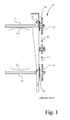
- a drive system 10 includes a pair of elongated driveshafts 12, 14 that are arranged to be substantially parallel. Each of driveshafts 12, 14 are rotatably coupled to a frame member 16 via a respective bearing 18, 20. Coupled to the ends of driveshafts 12, 14, is a respective sprocket 22, 24, which are drivably coupled by a chain (not shown) in a manner as is well known in the art. In this prior art arrangement, the teeth of sprockets 22, 24 are cantilevered outward on respective driveshafts 12, 14 with respect to bearings 18, 20.
- the invention is directed to a combine head.
- the combine head includes a frame, and an end wall coupled to the frame.
- a plurality of row units is coupled to the frame.
- a driveshaft is drivably coupled to the plurality of row units.
- a drive system includes a drive assembly.
- the drive assembly is coupled to the end wall and is coupled to the driveshaft.
- the drive assembly includes a bearing and a sprocket.
- the bearing rotatably supports the driveshaft, and defines a rotational axis of the driveshaft.
- a plane passes radially through the bearing perpendicular to the rotational axis.
- the sprocket is drivably coupled to the driveshaft.
- the sprocket has a plurality of teeth located around a perimeter of the sprocket, wherein the plurality of teeth is located so that the plane passes radially through the plurality of teeth.
- a combine 50 and a combine head 52 there is shown a combine 50 and a combine head 52.
- Fig. 2 is oriented with respect to a common orthogonal coordinate system in which the X-axis extends from the origin toward the rear of the combine and/or combine head in a longitudinal direction, the Z-axis extends from the origin vertically, and the Y- axis extends from the origin laterally, e.g., rightwardly, or orthogonal to the other two axes, across the combine and/or combine head.
- Combine 50 includes a feeder house 54 that extends from the front of combine 50.
- a front end 56 of feeder house 54 is configured to support combine head 52 in a manner known in the art.
- Combine head 52 defines a rectangular aperture or opening 58 that receives front end 56 of feeder house 54 as combine head 52 is mounted on combine 50 in a manner known in the art.
- combine head 52 such as a corn head in the embodiment shown, includes a combine head frame 100 to which a plurality of row units 102, e.g., corn head units, is coupled, e.g., by bolts and brackets.
- Each row unit of the plurality of row units 102 includes harvesting components 103, such as for example a pair of stalk rolls, gathering chains, etc., associated with each individual row unit for gathering crops.
- Combine head 52 also includes two row unit drive systems, a drive system 104-1 and a drive system 104-2, which may be substantially identical in configuration.
- Drive system 104-1 is configured to drive row units 102-1 of the plurality of row units 102 generally on the left side of combine head 52 and the other drive system 104-2 is configured to drive row units 102-2 of the plurality of row units 102 generally on the right side of combine head 52.
- each drive system 104-1, 104-2 includes a first driveshaft 106 for driving the row units 102 that extends through and is supported by the end sheet, or end wall, 108 of combine head 52.
- Row unit driveshaft 106 is drivably coupled to the plurality of row units 102, and more particularly, to the harvesting components 103 of the plurality of row units 102.
- a sprocket 110 is fixed to the end of each driveshaft 106.
- a plurality of teeth 110-1 is located around a perimeter of sprocket 110.
- a second sprocket 114 is supported on a second driveshaft 116 that extends through end wall 108 of combine head 52.
- a plurality of teeth 114-1 is located around a perimeter of sprocket 114.
- the outer perimeter of sprockets 110, 114 may be, but need not be, the same.
- the number of the plurality of perimetrical teeth 110-1 may be, but need not be, the same as the number of the plurality of perimetrical teeth 114-1.
- a chain 112 engages the teeth 110-1 of sprocket 110 and the teeth 114-1 of sprocket 114, and extends from sprocket 110 backward to sprocket 114, to drivably couple sprocket 110 to sprocket 114.
- An idler sprocket assembly 118 is attached to end wall 108, and provides adjustable tensioning of chain 112.
- a cover/chain guard 120 is provided to cover chain 112 and sprockets 110, 114, and is attached to end wall 108.
- these drive system components may be configured to drive all of the plurality of row units 102 using only one of the drive systems 104-1, 104-2.
- a single drive system e.g., either the left side drive system 104-1 or the mirror image right side drive system 104-2
- a lengthened driveshaft 106 that extends all the way across combine head 52 and is coupled to all of the plurality of row units 102.
- Each driveshaft 106 and driveshaft 116 is rotatably mounted in position relative to end wall 108 of combine head 52 by a respective first drive assembly 122-1 and a second drive assembly 122-2 that may be at least partially preassembled prior to attachment to end wall 108 of combine head 52.
- each drive assembly 122-1, 122-2 includes, for example, a bearing housing 124, a bearing 126, a hub 128, a seal 130, an O-ring 132, an outer snap ring 134, and an inner snap ring 136, as well as a respective sprocket 110 or 114.
- the drive assembly 122-1 will be described in more detail below, but it is to be understood that drive assembly 122-1 may be representative of the configuration of drive assembly 122-2 as well.
- drive assembly 122-1 and drive assembly 122-2 may be identical, or may be scaled differently (e.g., different sizes of bearings, hubs, etc.), depending on the application.
- the structural configuration of drive assembly 122-1 and drive assembly 122-2 is the same.
- bearing 126 when assembled, bearing 126 defines a rotational axis 138-1 of hub 128 and sprocket 110, which in turn is the rotational axis of driveshaft 106.
- bearing 126 is coaxial with hub 128 along axis 138-1.
- Teeth 110-1 of sprocket 110 are aligned along a plane 140 passing radially through bearing 126 relative to axis 138-1, i.e., perpendicular to axis 138-1.
- plane 140 is perpendicular to axis 138-1 and passes radially through both bearing 126 and all of the plurality of teeth 110-1 of sprocket 110.
- bearing 126 when assembled, bearing 126 defines a rotational axis 138-2 of hub 128 and sprocket 114, which in turn is the rotational axis of driveshaft 116.
- Bearing 126 may be, for example, a sealed bearing having an outer race 142 and an inner race 144, and a plurality of ball bearings 146 located between outer race 142 and inner race 144.
- Bearing housing 124 includes a first bore 148, a second bore 150, and a snap ring groove152.
- a diameter of first bore 148 is selected to accommodate the outer race 142 of bearing 126 in a snug press fit to mount bearing 126 to bearing housing 124.
- a diameter of second bore 150 is selected to accommodate seal 130 in a snug press fit.
- First bore 148 defines a bearing seat 154 at the end of the axial extent of first bore 148 along axis 138-1.
- Snap ring groove 152 is formed in first bore 148 to be axially separated from bearing seat 154 by a distance corresponding to a thickness of outer race 142 of bearing 126 (i.e., in the direction of axis 138-1).
- Second bore 150 defines a seal seat 156 at the end of second bore 150 along axis 138-1.
- Hub 128 includes a stub portion 158 and a shoulder 160 extending radially outward from stub portion 158.
- Shoulder 160 has an outer surface 162 for mating to a sprocket, e.g., sprocket 110 in this example, and an inner surface defining a bearing seat 164.
- a snap ring groove 166 is formed in an outer surface 168 of stub portion 158 to be axially separated from bearing seat 164 by a distance corresponding to a thickness of the inner race 144 of bearing 126 (i.e., in the direction of axis 138-1)
- An axial opening 170 is formed in and extends through hub 128 at a central region 172 of stub portion 158 along axis 138-1.
- the shape of axial opening 170 in a direction parallel to plane 140, i.e., perpendicular to axis 138-1, corresponds to the shape of the outer surface of the shaft, e.g., driveshaft 106 or 116, to be inserted into axial opening 170.
- the shape may be, for example, polygonal (e.g., hexagonal) to ensure that hub 128 and the inserted shaft rotate together coaxially about axis 138-1.
- seal 130 is inserted in a press (snug) fit into second bore 150 of bearing housing 124.
- Stub portion 158 of hub 128 is inserted in a snug fit into the inner race 144 of bearing 126 until inner race 144 engages bearing seat 164, and inner snap ring 136 is installed in snap ring groove 166 on stub portion 158 of hub 128.
- Outer race 142 of bearing 126 is pressed into first bore 148 of bearing housing 124 until outer race 142 engages bearing seat 154, and outer snap ring 134 is installed in snap ring groove 152.
- Outer snap ring 134 is installed at the outer side of bearing 126 to prevent axial movement of bearing 126 relative to bearing housing 124 along respective axis 138-1 (or axis 138-2).
- Inner snap ring 136 is installed at the inner side of bearing 126 to prevent axial movement of hub 128 relative to bearing 126 along the respective axis 138-1 (or axis 138-2).
- an end portion 174 of driveshaft 106 is inserted into axial opening 170 of hub 128 of drive assembly 122-1.
- Drive assembly 122-1 is then mounted to end wall 108, e.g., by one or more carriage bolts (not shown) passing through a respective opening in end wall 108 and through a corresponding opening in bearing housing 124, and threaded with a corresponding nut.
- end portion 174 of driveshaft 106 will be substantially flush with outer surface 162 of hub 128.
- driveshaft 106 is now rotatably supported by bearing 126 at rotational axis 138-1, which in turn becomes the rotational axis of driveshaft 106.
- O-ring 132 is installed in an O-ring groove formed in the outer surface 162 around axial opening 170.
- Sprocket 110 is coupled to end portion 174 of driveshaft 106 by an axially extending fastener, e.g., bolt 176, and sprocket 110 is coupled to shoulder 160 of hub 128 by a fastener, e.g., a ring of bolts 178.
- Another drive assembly 122-2 is similarly installed with respect to driveshaft 116 and sprocket 114, if not already installed.
- Chain 112 is installed over teeth 110-1 of sprocket 110 and teeth 114-1 of sprocket 114 to drivably couple drive assembly 122-1 to drive assembly 122-2, and the tension of chain 112 is adjusted by idler sprocket assembly 118.
- Cover/chain guard 120 may then be installed over chain 112, and attached by fasteners, e.g., screws or bolts, to end wall 108.
- each of sprockets 110, 114 has a dished, i.e., domed, shape that defines an interior recess 180 having a depth 182.
- Interior recess 180 may, for example, have a substantially concave shape.
- sprocket 110 has a dished shape to axially offset the plurality of teeth 110-1 from an axial outer portion 110-2 of sprocket 110.
- sprocket 114 has a dished shape to axially offset the plurality of teeth 114-1 from an axial outer portion 114-2 of sprocket 114 along axis 138-1.
- at least a portion of bearing 126 is located within interior recess 180 of the respective sprocket, e.g., sprocket 110.
- depth 182 is selected such that plane 140 radially passes both through all the perimetrical teeth 110-1 of sprocket 110 and through the axial center of bearing 126 (i.e., along axis 138-1) that supports sprocket 110 for rotation.
- depth 182 is selected such that plane 140 passes radially through both all the perimetrical teeth 114-1 of sprocket 114 and through the axial center of bearing 126 (i.e., along axis 138-2) that supports sprocket 114 for rotation.
- each sprocket 110, 114 is resisted by an opposing force applied by the respective bearing 126 in the same plane 140 perpendicular to the axis of rotation of the respective driveshaft 106, 116 (i.e., axis 138-1, 138-2, respectively).
- the configuration of sprocket 110 and its drive assembly 122-1 reduces the moment applied to the shaft 106 by sprocket 110 at the respective bearing 126 by applying loads to driveshaft 106 directly in the plane 140 of bearing 126, i.e., at different locations along driveshaft 106 than that of the configuration of Fig. 1.
- sprocket 114 and its drive assembly 122-2 reduces the moment applied to driveshaft 116 by sprocket 114 at the respective bearing 126 by applying loads to driveshaft 116 directly in the plane 140 of bearing 126, i.e., at different locations along driveshaft 116 than that of the configuration of Fig. 1. This reduces the bending moment on the respective driveshaft, which in turn reduces the resultant misalignment of the sprockets 110, 114 under heavy loads and the concomitant flexure and undue wear of chain 112.
Landscapes
- Life Sciences & Earth Sciences (AREA)
- Environmental Sciences (AREA)
- Shafts, Cranks, Connecting Bars, And Related Bearings (AREA)
- Motor Power Transmission Devices (AREA)
- Arrangement And Driving Of Transmission Devices (AREA)
Abstract
a first bearing (126) rotatably supporting said first driveshaft (106) and a first sprocket (110) being drivably coupled to said first driveshaft (106) and having a first plurality of teeth (110-1).
Description
- This invention relates to a combine head, comprising a frame; an end wall coupled to said frame; a plurality of row units coupled to said frame; a first driveshaft drivably coupled to said plurality of row units; and a drive system including a first drive assembly, wherein said first drive assembly is coupled to said end wall and coupled to said first driveshaft, said first drive assembly including a first bearing and a first sprocket, said first bearing rotatably supporting said first driveshaft, said first bearing defining a first rotational axis of said first driveshaft, and having a first plane passing radially through said first bearing perpendicular to said first rotational axis, said first sprocket being drivably coupled to said first driveshaft, said first sprocket having a first plurality of teeth located around a perimeter of said first sprocket.
- A combine head according to the preamble of claim 1 is described for example in
EP 0 491 405 A . - In the prior art, as illustrated in Fig. 1, a
drive system 10 includes a pair ofelongated driveshafts driveshafts frame member 16 via a respective bearing 18, 20. Coupled to the ends ofdriveshafts respective sprocket sprockets respective driveshafts bearings sprockets driveshafts driveshafts driveshafts - What is needed, therefore, is an improved combine row unit drive system that is more rigid and reduces wear on the sprockets and chains.
- This object is achieved with the subject matter of claim 1. The dependent claims recite advantageous embodiments.
- The invention is directed to a combine head. The combine head includes a frame, and an end wall coupled to the frame. A plurality of row units is coupled to the frame. A driveshaft is drivably coupled to the plurality of row units. A drive system includes a drive assembly. The drive assembly is coupled to the end wall and is coupled to the driveshaft. The drive assembly includes a bearing and a sprocket. The bearing rotatably supports the driveshaft, and defines a rotational axis of the driveshaft. A plane passes radially through the bearing perpendicular to the rotational axis. The sprocket is drivably coupled to the driveshaft. The sprocket has a plurality of teeth located around a perimeter of the sprocket, wherein the plurality of teeth is located so that the plane passes radially through the plurality of teeth.
- The above-mentioned and other features and advantages of this invention, and the manner of attaining them, will become more apparent and the invention will be better understood by reference to the following description of an embodiment of the invention taken in conjunction with the accompanying drawings, wherein:
- Fig. 1 is a top view of prior art driveshafts illustrating the tendency of the shafts to flex under high loads.
- Fig. 2 is a perspective view of a combine and a combine head, with the combine head being configured in accordance with an embodiment of the present invention.
- Fig. 3 is a bottom perspective view of the combine head of Fig. 2.
- Fig. 4 is a perspective view of the frame and end walls of the combine head of Fig. 3.
- Fig. 5 is an exploded view of a drive assembly of the combine head of Fig. 2.
- Fig. 6 is an assembled section view of the drive assembly of Fig. 5 taken along plane 6-6-6-6 of Fig. 5
- Corresponding reference characters indicate corresponding parts throughout the several views. The exemplifications set out herein illustrate an embodiment of the invention, in one form, and such exemplifications are not to be construed as limiting the scope of the invention in any manner.
- Referring now to the figures, and particularly Fig. 2, there is shown a
combine 50 and acombine head 52. Fig. 2 is oriented with respect to a common orthogonal coordinate system in which the X-axis extends from the origin toward the rear of the combine and/or combine head in a longitudinal direction, the Z-axis extends from the origin vertically, and the Y- axis extends from the origin laterally, e.g., rightwardly, or orthogonal to the other two axes, across the combine and/or combine head. - Combine 50 includes a
feeder house 54 that extends from the front ofcombine 50. Afront end 56 offeeder house 54 is configured to support combinehead 52 in a manner known in the art.Combine head 52 defines a rectangular aperture oropening 58 that receivesfront end 56 offeeder house 54 ascombine head 52 is mounted oncombine 50 in a manner known in the art. - Referring also to Figs. 3 and 4, combine
head 52, such as a corn head in the embodiment shown, includes acombine head frame 100 to which a plurality ofrow units 102, e.g., corn head units, is coupled, e.g., by bolts and brackets. Each row unit of the plurality ofrow units 102 includesharvesting components 103, such as for example a pair of stalk rolls, gathering chains, etc., associated with each individual row unit for gathering crops. -
Combine head 52 also includes two row unit drive systems, a drive system 104-1 and a drive system 104-2, which may be substantially identical in configuration. Drive system 104-1 is configured to drive row units 102-1 of the plurality ofrow units 102 generally on the left side ofcombine head 52 and the other drive system 104-2 is configured to drive row units 102-2 of the plurality ofrow units 102 generally on the right side ofcombine head 52. - As illustrated in Figs. 3-5, each drive system 104-1, 104-2 includes a
first driveshaft 106 for driving therow units 102 that extends through and is supported by the end sheet, or end wall, 108 ofcombine head 52.Row unit driveshaft 106 is drivably coupled to the plurality ofrow units 102, and more particularly, to theharvesting components 103 of the plurality ofrow units 102. With respect to each drive system 104-1, 104-2, asprocket 110 is fixed to the end of eachdriveshaft 106. A plurality of teeth 110-1 is located around a perimeter ofsprocket 110. Asecond sprocket 114 is supported on asecond driveshaft 116 that extends throughend wall 108 of combinehead 52. A plurality of teeth 114-1 is located around a perimeter ofsprocket 114. The outer perimeter ofsprockets - A
chain 112 engages the teeth 110-1 ofsprocket 110 and the teeth 114-1 ofsprocket 114, and extends fromsprocket 110 backward to sprocket 114, to drivably couplesprocket 110 to sprocket 114. Anidler sprocket assembly 118 is attached toend wall 108, and provides adjustable tensioning ofchain 112. A cover/chain guard 120 is provided tocover chain 112 andsprockets end wall 108. - In an alternative arrangement, these drive system components may be configured to drive all of the plurality of
row units 102 using only one of the drive systems 104-1, 104-2. In this arrangement, a single drive system (e.g., either the left side drive system 104-1 or the mirror image right side drive system 104-2) is provided to drive all of the plurality ofrow units 102 using a lengtheneddriveshaft 106 that extends all the way across combinehead 52 and is coupled to all of the plurality ofrow units 102. - Each
driveshaft 106 anddriveshaft 116 is rotatably mounted in position relative toend wall 108 ofcombine head 52 by a respective first drive assembly 122-1 and a second drive assembly 122-2 that may be at least partially preassembled prior to attachment toend wall 108 of combinehead 52. - Referring to Figs. 5 and 6, each drive assembly 122-1, 122-2 includes, for example, a
bearing housing 124, abearing 126, ahub 128, aseal 130, an O-ring 132, anouter snap ring 134, and aninner snap ring 136, as well as arespective sprocket - With respect to drive assembly 122-1, when assembled, bearing 126 defines a rotational axis 138-1 of
hub 128 andsprocket 110, which in turn is the rotational axis ofdriveshaft 106. In other words, bearing 126 is coaxial withhub 128 along axis 138-1. Teeth 110-1 ofsprocket 110 are aligned along aplane 140 passing radially through bearing 126 relative to axis 138-1, i.e., perpendicular to axis 138-1. In other words,plane 140 is perpendicular to axis 138-1 and passes radially through both bearing 126 and all of the plurality of teeth 110-1 ofsprocket 110. Likewise, with respect to drive assembly 122-2, when assembled, bearing 126 defines a rotational axis 138-2 ofhub 128 andsprocket 114, which in turn is the rotational axis ofdriveshaft 116. - Bearing 126 may be, for example, a sealed bearing having an
outer race 142 and aninner race 144, and a plurality ofball bearings 146 located betweenouter race 142 andinner race 144. -
Bearing housing 124 includes afirst bore 148, asecond bore 150, and a snap ring groove152. A diameter offirst bore 148 is selected to accommodate theouter race 142 of bearing 126 in a snug press fit to mountbearing 126 to bearinghousing 124. A diameter ofsecond bore 150 is selected to accommodateseal 130 in a snug press fit. First bore 148 defines abearing seat 154 at the end of the axial extent offirst bore 148 along axis 138-1.Snap ring groove 152 is formed infirst bore 148 to be axially separated from bearingseat 154 by a distance corresponding to a thickness ofouter race 142 of bearing 126 (i.e., in the direction of axis 138-1).Second bore 150 defines aseal seat 156 at the end ofsecond bore 150 along axis 138-1. -
Hub 128 includes astub portion 158 and ashoulder 160 extending radially outward fromstub portion 158.Shoulder 160 has anouter surface 162 for mating to a sprocket, e.g.,sprocket 110 in this example, and an inner surface defining abearing seat 164. Asnap ring groove 166 is formed in anouter surface 168 ofstub portion 158 to be axially separated from bearingseat 164 by a distance corresponding to a thickness of theinner race 144 of bearing 126 (i.e., in the direction of axis 138-1) - An
axial opening 170 is formed in and extends throughhub 128 at acentral region 172 ofstub portion 158 along axis 138-1. The shape ofaxial opening 170 in a direction parallel to plane 140, i.e., perpendicular to axis 138-1, corresponds to the shape of the outer surface of the shaft, e.g.,driveshaft axial opening 170. The shape may be, for example, polygonal (e.g., hexagonal) to ensure thathub 128 and the inserted shaft rotate together coaxially about axis 138-1. - In assembling drive assembly 122-1 or 122-2,
seal 130 is inserted in a press (snug) fit intosecond bore 150 of bearinghousing 124.Stub portion 158 ofhub 128 is inserted in a snug fit into theinner race 144 of bearing 126 untilinner race 144 engages bearingseat 164, andinner snap ring 136 is installed insnap ring groove 166 onstub portion 158 ofhub 128.Outer race 142 of bearing 126 is pressed intofirst bore 148 of bearinghousing 124 untilouter race 142 engages bearingseat 154, andouter snap ring 134 is installed insnap ring groove 152.Outer snap ring 134 is installed at the outer side of bearing 126 to prevent axial movement of bearing 126 relative to bearinghousing 124 along respective axis 138-1 (or axis 138-2).Inner snap ring 136 is installed at the inner side of bearing 126 to prevent axial movement ofhub 128 relative to bearing 126 along the respective axis 138-1 (or axis 138-2). - The example that follows describes the mounting of the preassembled drive assembly 122-1 with specific reference to
driveshaft 106. However, it is to be understood that the principles of assembly and operation relative to drive assembly 122-1 anddriveshaft 106 may be applied to drive assembly 122-2 anddriveshaft 116, as well as any other similar configured drive assembly/driveshaft arrangement. - Referring to Fig. 5, an
end portion 174 ofdriveshaft 106 is inserted intoaxial opening 170 ofhub 128 of drive assembly 122-1. Drive assembly 122-1 is then mounted to endwall 108, e.g., by one or more carriage bolts (not shown) passing through a respective opening inend wall 108 and through a corresponding opening in bearinghousing 124, and threaded with a corresponding nut. At this time,end portion 174 ofdriveshaft 106 will be substantially flush withouter surface 162 ofhub 128. Also,driveshaft 106 is now rotatably supported by bearing 126 at rotational axis 138-1, which in turn becomes the rotational axis ofdriveshaft 106. O-ring 132 is installed in an O-ring groove formed in theouter surface 162 aroundaxial opening 170.Sprocket 110 is coupled to endportion 174 ofdriveshaft 106 by an axially extending fastener, e.g.,bolt 176, andsprocket 110 is coupled toshoulder 160 ofhub 128 by a fastener, e.g., a ring ofbolts 178. Another drive assembly 122-2 is similarly installed with respect todriveshaft 116 andsprocket 114, if not already installed.Chain 112 is installed over teeth 110-1 ofsprocket 110 and teeth 114-1 ofsprocket 114 to drivably couple drive assembly 122-1 to drive assembly 122-2, and the tension ofchain 112 is adjusted byidler sprocket assembly 118. Cover/chain guard 120 may then be installed overchain 112, and attached by fasteners, e.g., screws or bolts, to endwall 108. - As best shown in Figs. 5 and 6, each of
sprockets interior recess 180 having adepth 182.Interior recess 180 may, for example, have a substantially concave shape. In other words,sprocket 110 has a dished shape to axially offset the plurality of teeth 110-1 from an axial outer portion 110-2 ofsprocket 110. Likewise,sprocket 114 has a dished shape to axially offset the plurality of teeth 114-1 from an axial outer portion 114-2 ofsprocket 114 along axis 138-1. As such, as illustrated in Fig. 6, at least a portion of bearing 126, for example a substantial portion in the present embodiment, is located withininterior recess 180 of the respective sprocket, e.g.,sprocket 110. - As best shown in Fig. 6, for
sprocket 110,depth 182 is selected such thatplane 140 radially passes both through all the perimetrical teeth 110-1 ofsprocket 110 and through the axial center of bearing 126 (i.e., along axis 138-1) that supportssprocket 110 for rotation. Likewise, forsprocket 114,depth 182 is selected such thatplane 140 passes radially through both all the perimetrical teeth 114-1 ofsprocket 114 and through the axial center of bearing 126 (i.e., along axis 138-2) that supportssprocket 114 for rotation. - The load on each
sprocket respective bearing 126 in thesame plane 140 perpendicular to the axis of rotation of therespective driveshaft 106, 116 (i.e., axis 138-1, 138-2, respectively). In comparison to the prior art configuration of Fig. 1, the configuration ofsprocket 110 and its drive assembly 122-1 reduces the moment applied to theshaft 106 bysprocket 110 at therespective bearing 126 by applying loads to driveshaft 106 directly in theplane 140 of bearing 126, i.e., at different locations alongdriveshaft 106 than that of the configuration of Fig. 1. Similarly, the configuration ofsprocket 114 and its drive assembly 122-2 reduces the moment applied todriveshaft 116 bysprocket 114 at therespective bearing 126 by applying loads to driveshaft 116 directly in theplane 140 of bearing 126, i.e., at different locations alongdriveshaft 116 than that of the configuration of Fig. 1. This reduces the bending moment on the respective driveshaft, which in turn reduces the resultant misalignment of thesprockets chain 112.
Claims (6)
- A combine head (52), comprising:a frame (100);an end wall (108) coupled to said frame (100);a plurality of row units (102) coupled to said frame (100);a first driveshaft (106) drivably coupled to said plurality of row units (102); anda drive system (104-1, 104-2) including a first drive assembly (122-1), wherein:said first drive assembly (122-1) is coupled to said end wall (108) and coupled to said first driveshaft (106), said first drive assembly (122-1) including:a first bearing (126) and a first sprocket (110), said first bearing (126) rotatably supporting said first driveshaft (106), said first bearing (126) defining a first rotational axis of said first driveshaft (106), and having a first plane (140) passing radially through said first bearing (126) perpendicular to said first rotational axis, said first sprocket (110) being drivably coupled to said first driveshaft (106), said first sprocket (110) having a first plurality of teeth (110-1) located around a perimeter of said first sprocket (110), characterized in that said first plurality of teeth (110-1) are located so that said first plane (140) passes radially through said first plurality of teeth (110-1).
- The combine head (52) of claim 1, further comprising a second driveshaft (116), and wherein:said drive system (104-1, 104-2) further includes a second drive assembly (122-2) and a chain (112), said second drive assembly (122-2) being coupled to said end wall (108) and coupled to said second driveshaft (116), said second drive assembly (122-2) including:a second bearing and a second sprocket (114), said second bearing rotatably supporting said second driveshaft (116), said second bearing defining a second rotational axis of said second driveshaft (116), and having a second plane passing radially through said second bearing perpendicular to said second axis, said second sprocket (114) being drivably coupled to said second driveshaft (116), said second sprocket (114) having a second plurality of teeth (114-1) located around a perimeter of said second sprocket (114), said second plurality of teeth (114-1) being located so that said second plane passes radially through said second plurality of teeth (114-1),said chain (112) engaging said first plurality of teeth (110-1) of said first sprocket (110) and said second plurality of teeth (114-1) of said second sprocket (114).
- The combine head of claim 1 or 2, wherein:said first sprocket (110) has a dished shape to axially offset said first plurality of teeth (110-1) from an axial outer portion of said first sprocket (110).
- The combine head of one of claims 2 or 3, wherein:said second sprocket (114) has a dished shape to axially offset said second plurality of teeth (11-4-1) from an axial outer portion of said second sprocket (110).
- The combine head of claim 3 or 4, wherein:said dished shape of said first sprocket (110) defines a first interior recess, and wherein at least a portion of said first bearing (126) is located within said first interior recess.
- The combine head of one of claims 4 or 5, wherein:said dished shape of said second sprocket (114) defines a second interior recess, and wherein at least a portion of said second bearing is located within said second interior recess.
Applications Claiming Priority (2)
| Application Number | Priority Date | Filing Date | Title |
|---|---|---|---|
| US77455806P | 2006-02-17 | 2006-02-17 | |
| US11/588,656 US7694500B2 (en) | 2006-02-17 | 2006-10-26 | Drive assembly and drive system for a combine head |
Publications (2)
| Publication Number | Publication Date |
|---|---|
| EP1820387A1 true EP1820387A1 (en) | 2007-08-22 |
| EP1820387B1 EP1820387B1 (en) | 2008-09-03 |
Family
ID=38123733
Family Applications (1)
| Application Number | Title | Priority Date | Filing Date |
|---|---|---|---|
| EP07102054A Ceased EP1820387B1 (en) | 2006-02-17 | 2007-02-09 | Combine head with a drive assembly |
Country Status (3)
| Country | Link |
|---|---|
| US (1) | US7694500B2 (en) |
| EP (1) | EP1820387B1 (en) |
| DE (1) | DE602007000099D1 (en) |
Cited By (1)
| Publication number | Priority date | Publication date | Assignee | Title |
|---|---|---|---|---|
| EP2781149A2 (en) | 2013-03-21 | 2014-09-24 | Deere & Company | Sectional driveshaft arrangement for a corn head |
Families Citing this family (12)
| Publication number | Priority date | Publication date | Assignee | Title |
|---|---|---|---|---|
| WO2011014915A1 (en) * | 2009-08-04 | 2011-02-10 | Ryan Burke | A torsion cushioning sprocket |
| DE102012106603A1 (en) * | 2012-07-20 | 2014-05-15 | Claas Hungaria Kft. | Series independent attachment for harvesting stemmed crops |
| US9668420B2 (en) | 2013-02-20 | 2017-06-06 | Deere & Company | Crop sensing display |
| US9066465B2 (en) | 2013-02-20 | 2015-06-30 | Deere & Company | Soil compaction reduction system and method |
| US9693503B2 (en) | 2013-02-20 | 2017-07-04 | Deere & Company | Crop sensing |
| US10178828B2 (en) | 2013-02-20 | 2019-01-15 | Deere & Company | Per plant crop sensing resolution |
| US11212962B2 (en) | 2013-02-20 | 2022-01-04 | Deere & Company | Field condition determination |
| US9282693B2 (en) | 2013-02-20 | 2016-03-15 | Deere & Company | Data encoding with planting attributes |
| US9578804B2 (en) * | 2014-04-23 | 2017-02-28 | Cnh Industrial America Llc | Header for an agricultural harvester with independent sub-system drives |
| US9913430B2 (en) * | 2014-09-15 | 2018-03-13 | Cnh Industrial America Llc | Power takeoff drive assembly for a corn header of an agricultural harvester |
| JP7134140B2 (en) * | 2019-06-25 | 2022-09-09 | 株式会社クボタ | harvester |
| DE102023120836A1 (en) * | 2023-08-06 | 2025-02-06 | Claas Industrietechnik Gmbh | corn picker and agricultural machinery equipped with it |
Citations (2)
| Publication number | Priority date | Publication date | Assignee | Title |
|---|---|---|---|---|
| EP0491405A1 (en) | 1990-12-18 | 1992-06-24 | Capello F.Lli Renato E Francesco S.N.C. | A foldable head for a maize picker machine |
| US6651412B1 (en) * | 2002-10-29 | 2003-11-25 | New Holland North America, Inc. | Forward clutch drive for windrow header with positive reverse drive |
Family Cites Families (11)
| Publication number | Priority date | Publication date | Assignee | Title |
|---|---|---|---|---|
| US2823553A (en) * | 1955-07-07 | 1958-02-18 | Parkersburg Aetna Corp | Sprocket idler |
| NL6716443A (en) * | 1967-12-04 | 1969-06-06 | ||
| NL169947C (en) * | 1973-06-14 | 1984-03-16 | Zweegers P | MOWER. |
| US3985038A (en) * | 1975-04-14 | 1976-10-12 | Deere & Company | Self-aligning idler |
| US4216641A (en) * | 1979-06-13 | 1980-08-12 | Sperry Corporation | Crop harvesting machine |
| EP0149113A3 (en) * | 1983-12-13 | 1986-02-19 | Ing. Alfred Schmidt Gmbh | Mowing device, especially for grassy areas at airports |
| FR2617002B1 (en) * | 1987-06-26 | 1991-06-07 | Kuhn Sa | MOWER PROVIDED WITH TWO GROUPS OF MOWERS |
| US5133174A (en) * | 1991-01-28 | 1992-07-28 | Parsons Jr Ralph L | Hydraulically driven mowing unit |
| GB2289201A (en) * | 1994-05-07 | 1995-11-15 | Ford New Holland Nv | Drive reversal for agricultural harvester |
| DE29702902U1 (en) * | 1997-02-19 | 1998-06-18 | Maschinenfabrik Kemper GmbH, 48703 Stadtlohn | Machine for row-independent mowing of maize and the like stem-like crop |
| DE19906003A1 (en) * | 1999-02-15 | 2000-08-17 | Schaeffler Waelzlager Ohg | Chain wheel for IC engines has noise and vibration damper plug located on either side of chain wheel and outside range of chain |
-
2006
- 2006-10-26 US US11/588,656 patent/US7694500B2/en active Active
-
2007
- 2007-02-09 EP EP07102054A patent/EP1820387B1/en not_active Ceased
- 2007-02-09 DE DE602007000099T patent/DE602007000099D1/en active Active
Patent Citations (2)
| Publication number | Priority date | Publication date | Assignee | Title |
|---|---|---|---|---|
| EP0491405A1 (en) | 1990-12-18 | 1992-06-24 | Capello F.Lli Renato E Francesco S.N.C. | A foldable head for a maize picker machine |
| US6651412B1 (en) * | 2002-10-29 | 2003-11-25 | New Holland North America, Inc. | Forward clutch drive for windrow header with positive reverse drive |
Cited By (2)
| Publication number | Priority date | Publication date | Assignee | Title |
|---|---|---|---|---|
| EP2781149A2 (en) | 2013-03-21 | 2014-09-24 | Deere & Company | Sectional driveshaft arrangement for a corn head |
| US9072221B2 (en) | 2013-03-21 | 2015-07-07 | Deere & Company | Sectional driveshaft arrangement for a corn head |
Also Published As
| Publication number | Publication date |
|---|---|
| US7694500B2 (en) | 2010-04-13 |
| US20070197327A1 (en) | 2007-08-23 |
| EP1820387B1 (en) | 2008-09-03 |
| DE602007000099D1 (en) | 2008-10-16 |
Similar Documents
| Publication | Publication Date | Title |
|---|---|---|
| EP1820387B1 (en) | Combine head with a drive assembly | |
| US9867335B1 (en) | Automatic tensioning control deck plate system | |
| US5507136A (en) | Mower with a cutting device and supporting structure | |
| US11834128B2 (en) | Pedelec bottom-bracket drive unit | |
| CA1145561A (en) | Auger conveyor for a crop harvester | |
| US7070042B2 (en) | Blade pulley | |
| EP3597025B1 (en) | Harvesting head with tension frame assembly and central pivot | |
| EP1815733B1 (en) | Roller assembly of a belt drive system | |
| CA2854403A1 (en) | Drive coupler for a reciprocating knife | |
| EP2084954B1 (en) | Stalk roll | |
| US11968926B2 (en) | Clamp bearing for forage harvester | |
| EP2027763A2 (en) | A Timing Crank For A Cylindrical Conveyor For An Agricultural Harvester | |
| US9192101B2 (en) | Pick-up tine bracket with flange | |
| US7478523B2 (en) | Pickup guard mounting arrangement | |
| US20220282774A1 (en) | Adjustable angular orientation of a freely running sheave of a belt drive | |
| US20180199510A1 (en) | Stalk roll shaft retention assembly | |
| AU2018222905B2 (en) | Modular mounting system for a cotton harvester | |
| AU2018200186B2 (en) | Cutting assembly for a plant cutting machine | |
| US6684615B1 (en) | Hinge system for articulating mower decks | |
| EP2815639B1 (en) | Pick-up tine bracket with flange | |
| US20080022864A1 (en) | Roller assembly for agricultural baler | |
| BRPI0700404B1 (en) | drive assembly for a combination head, combination head and method for driving a combination head | |
| EP4388842A1 (en) | Sprocket shield assembly for feeder of agricultural vehicle | |
| JP2020182388A (en) | combine | |
| KR20190138349A (en) | Bracket for cultivator |
Legal Events
| Date | Code | Title | Description |
|---|---|---|---|
| PUAI | Public reference made under article 153(3) epc to a published international application that has entered the european phase |
Free format text: ORIGINAL CODE: 0009012 |
|
| AK | Designated contracting states |
Kind code of ref document: A1 Designated state(s): AT BE BG CH CY CZ DE DK EE ES FI FR GB GR HU IE IS IT LI LT LU LV MC NL PL PT RO SE SI SK TR |
|
| AX | Request for extension of the european patent |
Extension state: AL BA HR MK YU |
|
| 17P | Request for examination filed |
Effective date: 20080222 |
|
| AKX | Designation fees paid |
Designated state(s): DE HU IT |
|
| GRAP | Despatch of communication of intention to grant a patent |
Free format text: ORIGINAL CODE: EPIDOSNIGR1 |
|
| GRAS | Grant fee paid |
Free format text: ORIGINAL CODE: EPIDOSNIGR3 |
|
| GRAA | (expected) grant |
Free format text: ORIGINAL CODE: 0009210 |
|
| AK | Designated contracting states |
Kind code of ref document: B1 Designated state(s): DE HU IT |
|
| REF | Corresponds to: |
Ref document number: 602007000099 Country of ref document: DE Date of ref document: 20081016 Kind code of ref document: P |
|
| REG | Reference to a national code |
Ref country code: HU Ref legal event code: AG4A Ref document number: E004749 Country of ref document: HU |
|
| PLBE | No opposition filed within time limit |
Free format text: ORIGINAL CODE: 0009261 |
|
| STAA | Information on the status of an ep patent application or granted ep patent |
Free format text: STATUS: NO OPPOSITION FILED WITHIN TIME LIMIT |
|
| 26N | No opposition filed |
Effective date: 20090604 |
|
| PGRI | Patent reinstated in contracting state [announced from national office to epo] |
Ref country code: IT Effective date: 20110501 |
|
| PGFP | Annual fee paid to national office [announced via postgrant information from national office to epo] |
Ref country code: HU Payment date: 20140124 Year of fee payment: 8 Ref country code: IT Payment date: 20140224 Year of fee payment: 8 |
|
| PG25 | Lapsed in a contracting state [announced via postgrant information from national office to epo] |
Ref country code: HU Free format text: LAPSE BECAUSE OF NON-PAYMENT OF DUE FEES Effective date: 20150210 |
|
| PG25 | Lapsed in a contracting state [announced via postgrant information from national office to epo] |
Ref country code: IT Free format text: LAPSE BECAUSE OF NON-PAYMENT OF DUE FEES Effective date: 20150209 |
|
| PGFP | Annual fee paid to national office [announced via postgrant information from national office to epo] |
Ref country code: DE Payment date: 20240119 Year of fee payment: 18 |
|
| REG | Reference to a national code |
Ref country code: DE Ref legal event code: R119 Ref document number: 602007000099 Country of ref document: DE |
|
| PG25 | Lapsed in a contracting state [announced via postgrant information from national office to epo] |
Ref country code: DE Free format text: LAPSE BECAUSE OF NON-PAYMENT OF DUE FEES Effective date: 20250902 |