EP1819112A1 - System and method of sharing auto-reply information - Google Patents
System and method of sharing auto-reply information Download PDFInfo
- Publication number
- EP1819112A1 EP1819112A1 EP06101608A EP06101608A EP1819112A1 EP 1819112 A1 EP1819112 A1 EP 1819112A1 EP 06101608 A EP06101608 A EP 06101608A EP 06101608 A EP06101608 A EP 06101608A EP 1819112 A1 EP1819112 A1 EP 1819112A1
- Authority
- EP
- European Patent Office
- Prior art keywords
- user
- message
- current status
- network
- status information
- Prior art date
- Legal status (The legal status is an assumption and is not a legal conclusion. Google has not performed a legal analysis and makes no representation as to the accuracy of the status listed.)
- Granted
Links
Images


Classifications
-
- H—ELECTRICITY
- H04—ELECTRIC COMMUNICATION TECHNIQUE
- H04L—TRANSMISSION OF DIGITAL INFORMATION, e.g. TELEGRAPHIC COMMUNICATION
- H04L51/00—User-to-user messaging in packet-switching networks, transmitted according to store-and-forward or real-time protocols, e.g. e-mail
-
- H—ELECTRICITY
- H04—ELECTRIC COMMUNICATION TECHNIQUE
- H04L—TRANSMISSION OF DIGITAL INFORMATION, e.g. TELEGRAPHIC COMMUNICATION
- H04L51/00—User-to-user messaging in packet-switching networks, transmitted according to store-and-forward or real-time protocols, e.g. e-mail
- H04L51/21—Monitoring or handling of messages
- H04L51/234—Monitoring or handling of messages for tracking messages
Definitions
- the present invention relates generally to telecommunication networks and in particular to a network where each user can activate an auto-reply feature to indicate that the user is unavailable to receive messages.
- Electronic mail (e-mail) applications such as Microsoft® Outlook TM and Entourage TM , Netscape® Messenger TM , Eudora TM , Pegasus TM and Oracle TM Email enable users to set an auto-reply that automatically replies to incoming messages with a customized text message.
- This automatic reply feature is known in MS Outlook as "Out of Office Assistant", in Netscape Messenger as "Vacation Message”.
- MS Outlook In Eudora, MS Entourage, Pegasus Mail and Oracle Email, it is simply known as "auto-reply”.
- the auto-reply feature enables a user to type and save a brief auto-reply message that will then be automatically sent in reply to all incoming messages or to a subset of those incoming messages based on user-determined rules.
- the usual custom is for the user to indicate that he or she is away from the office until a certain date, to specify at least one alternate contact, and to provide phone, fax, email and/or other contact information for the alternate contact.
- FIG. 1 is a schematic layout of a network incorporating a system for sharing auto-reply information among other network users in accordance with an embodiment of the present invention
- FIG. 2 is a schematic layout of a network incorporating a system for disseminating auto-reply information to other users' address books in accordance with another embodiment of the present invention
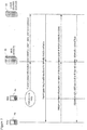
- FIG. 3 is a message flow diagram schematically illustrating a method of updating a user's address book in response to another user activating his auto-reply feature, in accordance with an aspect of the present invention
- FIG. 4 is a schematic layout of a network incorporating a system for sharing auto-reply information, illustrating an auto-reply feature that enables one user to indicate that he is unavailable and further illustrating the message routing options that are presented to another user when that user attempts to send a message to the user who has indicated that he is unavailable, in accordance with an aspect of the present invention.
- FIG. 5 is a schematic layout of a network in which a Blackberry Enterprise Server (BES) is installed behind a corporate firewall and wherein a mail server tracks each user's current status in accordance with another embodiment of the present invention.
- BES Blackberry Enterprise Server
- the invention seeks to reduce redundant and wasteful communications by providing a sender, prior to sending a message, with useful information about an intended recipient's availability to receive the message. This is preferably accomplished by tracking the activation and deactivation of each user's auto-reply feature, or "out of office assistant".
- the auto-reply feature provides current status information (i.e. whether the user is available or unavailable to receive messages) and optionally also includes a return date and an alternate contact (which can be specified using the auto-reply feature).
- a user status server collects and periodically updates the current status information for each user.
- the user status server then shares the current status information with other users in a network by disseminating or sharing this current status information for each user among all other users to make every user aware of every other user's availability to receive messages.
- the user status server can communicate only the current status information about those contacts appearing in each user's address book, to avoid unduly taxing network resources.
- an aspect of the present invention preferably provides a system for intelligently routing communications to networked users based on user availability.
- the system includes a plurality of communications devices being adapted to communicate with each other through a mail server connected to the network, each communications device enabling a user of the device to activate and deactivate an auto-reply feature that automatically replies to incoming messages.
- the system also includes at least one device connected to the network for receiving, storing and updating current status information for each user, the current status information including an indication as to whether each user is available or unavailable to receive a message.
- the device is a user status server communicatively connected to the mail server to enable the mail server to route a message from a sender to a recipient provided the current status information of the recipient indicates that the recipient is available to receive the message.
- the message routing options preferably include a first option of sending the message to the user regardless of the user's current unavailability, a second option of not sending the message at all, a third option of routing the message to at least one specified alternate contact, and a fourth option of sending the message to the user while sending a copy of the message to the alternate contact.
- the user status server preferably periodically communicates current status information to every user actively connected to the network in order to update each user's address book with current status information for every other user listed in each address book.
- the user status server preferably further communicates to all users a return date and an alternate contact for each user whose auto-reply feature is activated, whereby each user's address book can store and display the return date and alternate contact for each user whose current status information indicates that the user is unavailable.
- a further aspect of the present invention preferably provides a method of disseminating user availability information through a network to improve communication efficiency.
- the method includes the steps of determining a current status of each user of the network to determine if each user is currently available to be a recipient of a message; forwarding messages from a sender to the recipient when the recipient's current status indicates to the sender that the recipient is currently available to receive messages; and providing message options to the sender when an intended recipient's current status indicates to the sender that the intended recipient is unavailable to receive the message.
- the determining step preferably includes the steps of, for each user, assuming as a default status that the user is available to receive messages and updating the current status to indicate that the user is unavailable to receive messages in response to activation of the auto-reply feature.
- the determining step preferably further includes the step of updating the current status to indicate that the user is once again available to receive messages in response to deactivation of the auto-reply feature.
- the updating steps preferably further include the step of periodically interrogating the mail server to determine which contacts are listed in each user's address book and to communicate to each user only the current status information for the contacts listed in that user's address book.
- a further aspect of the present invention preferably provides a mobile wireless terminal device enabled for wireless communication with a data network via a wireless network.
- the device includes a memory and a microprocessor for executing an e-mail application, the e-mail application being adapted to store and update current status information for at least one other network user, the current status information being indicative of the at least one other user's availability to receive an e-mail.
- the current status information preferably further includes a date of anticipated availability for the at least one other network user when that other network user is indicated to be currently unavailable.
- the current status information preferably further comprises an alternate contact person and respective contact information for the alternate contact person.
- the present invention preferably provides a method and system for sharing auto-reply information with other network users to make users aware of other users' unavailability to receive messages before those messages are sent and for providing message routing options when intended recipients are unavailable. Embodiments of the invention are described below, by way of example only, with reference to FIGs. 1-5.
- a system in accordance with a preferred embodiment of the present invention generally includes a wireless network 2 hosting a plurality of wireless communication devices 4a, 4b, 4c, 4d and 4e (also known as “terminal devices").
- the wireless communication devices can be any of a wide variety of wireless devices including but not limited to wireless-enabled PDAs 4a, 4b, 4c, mobile or cellular telephones 4d, wireless-enabled laptop computers 4e, self-service kiosks (not shown) and two-way pagers (not shown).
- an Application Gateway (AG) 6 is coupled between the wireless network 2 and a data network 8, such as for example, the Internet.
- the AG 2 generally operates to mediate data traffic flowing between wireless communication devices 4a, 4b, 4c, 4d, 4e connected to the wireless network 2 and data services accessible through the data network 8 in the manner described in Applicant's co-pending United States Patent Publications Nos. 2004/0215700 and 2004/0220998 , both of which are incorporated herein by reference.
- These wireless communication devices generally include a microprocessor connected to an RF section for wireless communications, a memory (at least a portion of which will normally be non-volatile), and a user interface (UI) including a display and one or more user input devices (UID), e.g. a keyboard, thumb-wheel, stylus, microphone, etc.
- the microprocessor operates under software control to provide the functionality of the terminal device.
- the software is designed on a layered model, in which a runtime environment (RE) translates between application software, such as an e-mail application, and the native machine-language of the terminal device to control the terminal device hardware, and communicate with data services.
- RE runtime environment
- operation of the AG 2 enables a software application (e.g. an e-mail application such as MS Outlook) executing in a terminal device to communicate with data services (not shown) offered through the data network 6.
- a software application e.g. an e-mail application such as MS Outlook
- This operation may, for example, include accessing and downloading files from back-end data sources (not shown) connected to the data network 6 or downloading or uploading e-mail messages to and from one or more e-mail exchange servers, or simply "mail servers".
- a mail server 10 is connected to the data network for handling e-mail for a plurality of desktop mail clients running on respective personal computers 12a, 12b, 12c, as is well known in the art.
- desktop mail clients could be running on workstations or laptops or any other such computing device.
- the system in accordance with a preferred embodiment of the present invention further includes a networked device having both data storage and processing capability, such as for example, a user status server 14 connected to the mail server (or alternatively the user status server 14 can be integrated within the mail server).
- the user status server 14 receives, stores and updates current status information for users of the network.
- the current status information includes whether a given user is available or unavailable to receive messages.
- the system determines a user's availability based on whether or not the auto-reply feature in the user's e-mail application has been activated.
- auto-reply or “auto-reply feature” will be used generically to encompass any type of automatic reply functionality whether it is called “Auto-reply” (as it is in Eudora, MS Entourage, Pegasus Mail and Oracle Email) or whether it is called “Out of Office Assistant” as it is in MS Outlook, or "Vacation Message” as it is in Netscape Messenger).
- the user status server 14 can also be referred to as an "out of office server", although this terminology should not be construed as implying that the user is physically out of the office.
- out of office means unavailable and does not mean that a user is physically out of the office but roaming with a wireless device and thus available to receive messages. Therefore, though the expression “out of office”, has been popularized by Microsoft, it will not be used in this specification in order to avoid possible confusion between unavailability and wirelessly roaming away from one's office.
- the user status server 14 tracks the activation and deactivation of the auto-reply features for each user in order to continually collect and update current status information for that user.
- the current status information also preferably includes a return date for the return to work of the user and at least one alternate contact to whom messages can be directed for immediate resolution of an urgent matter.
- the user status server 14 stores and updates current status information for each user in the network (or alternatively a predefined subset thereof).
- the user status server 14 can track a much larger number of users.
- Amy, Bob and Carol have their own personal computers 12a, 12b, 12c, respectively, with desktop mail clients connected to the mail server 10 and that each of them also has a wireless PDA for communicating when physically away from their desk. If Bob is planning to be away on holiday, he sets the auto-reply feature in his e-mail application using either his personal computer 12b or his PDA 4b.
- the mail server 10 synchronizes the desktop mail client with the PDA, in a manner known in the art.
- the mail server 10 communicates the activation of the auto-reply to the user status server 14 which then updates the current status information for Bob to indicate that he is unavailable. If Bob specified a return date (which in this example he did, namely January 1, 2005) and an alternate contact (which in this example he also did, namely Amy), then this additional information is also passed along to the user status server 14 where it is stored in the current status information for Bob. Therefore, as shown in FIG. 1, the user status server has been updated to indicate that Bob is presently unavailable, that he returns (i.e. becomes available again) on January 1, 2005 and that in his absence urgent inquiries and other pressing matters can be directed to Amy.
- the user status server 14 effectively hosts a database that stores and updates each user's status.
- the auto-reply feature when activated, automatically communicates the status information, return date and alternate contacts (and any other information that may be added) to the user status server.
- this data could be fetched or extracted by the user status server 14 by interrogating the mail server 10.
- FIG. 2 shows schematically how the user status server 14 can communicate its stored and updated current status information to the various users of the network. For example, and assuming again that Bob is unavailable and that Amy and Carol remain available, the user status server 14 periodically disseminates current status information to Amy's PDA 4a and Carol's PDA 4c (and optionally also to Bob's PDA 4b even if he is away on holiday). This current status information is disseminated to the PDAs via the mail server 10, data network 8, AG 6 and wireless network 2.
- the mail server 10 can also concurrently disseminate this current status information to the desktop mail clients on Amy's personal computer 12a and Carol's personal computer 12c (and optionally also to Bob's personal computer 12b, even if Bob is unavailable in case Bob wishes to e-mail another user while he himself is unavailable).
- the current status information can be disseminated first to PDAs and then the mail server 10 can synchronize the information to the desktop mail clients, or vice versa.
- the auto-reply can prompt the user to specify whether the user wishes to receive current status information on the other users.
- Whether current status information is disseminated to absent or unavailable users can also be determined by a system setting at the user status server that enables an organization of users to either disseminate as a general rule current status information to everyone all the time, or to reduce network bandwidth requirements by only disseminating current status information to active or available users.
- the current status information is disseminated to other users' address books so that users are made readily aware of other users' availability, return dates and alternate contacts.
- current status information on each and every user is disseminated to all users.
- current status information is disseminated intelligently, based on address book contacts or other such contact lists.
- the user status server 14 periodically interrogates the mail server 10 to extract for each user that user's list of contacts. Accordingly, current status information is only disseminated to a subset of users, representing a particular user's contacts, which thus reduces network bandwidth requirements.
- FIG. 2 only shows the address books on the PDAs, although the mail server 10 would in most instances synchronize the address books on the desktop mail clients, in a manner known in the art.
- Amy's address book is updated to indicate that her contact Bob is now unavailable, that his return date is 1/1/05 and that she herself has been designated as Bob's alternate contact.
- Carol's address book is updated similarly to Amy's, to also shown that Bob is unavailable, that he returns on 1/1/05 and that Amy is Bob's alternate contact.
- Bob's address book can also be updated with the same information as Amy's and Carol's address books. Although, depending on whether Bob or his organization wishes to have the system maintain an updated address book for him while he is away, it is not strictly necessary to update Bob's address book.
- FIG. 3 is a message flow diagram schematically illustrating a method of updating a user's address book in response to another user activating his auto-reply feature, in accordance with an aspect of the present invention.
- Bob activates the auto-reply feature.
- the auto-reply feature communicates current status information about Bob, namely his unavailability, return date and alternate contacts, to the user status server 14 via the mail server 10.
- the user status server 14 then interrogates Amy's address book stored on her PDA via the mail server 10 to identify Amy's contacts.
- the mail server 10 can cache a copy of Amy's address book in which case the user status server queries the mail server (assuming the mail server has already obtained the address book from Amy's PDA).
- Amy's PDA 4a (or the mail server 10) then returns to the user status server 14 a listing of all of Amy's contacts. Since one of the contacts appearing in Amy's address book is Bob, the user status server updates Amy's address book with current status information about Bob.
- this scenario shows a pair of users using wireless PDAs, the method could be performed instead using desktop mail clients on person computers, workstations, laptops, wireless devices or any other combination of communication devices capable of connecting to and exchanging data with the network.
- FIG. 4 is a schematic layout of a network incorporating a system for sharing auto-reply information, illustrating an auto-reply feature that enables one user to indicate that he is unavailable and further illustrating the message routing options that are presented to another user when that user attempts to send a message to the user who has indicated that he is unavailable, in accordance with an aspect of the present invention.
- the system in accordance with a preferred embodiment of the present invention, includes an auto-reply feature that prompts the user to specify whether he is available to receive messages or unavailable to receive messages. This can be done by providing a clickable toggle to switch between unavailable and available.
- the auto-reply feature also prompts the user to specify a return date in a return date field.
- the auto-reply feature also prompts the user to specify at least one alternate contact and to provide that contact's e-mail address, phone or fax numbers.
- the system could also perform a check to make sure that the specified alternate contact is not also unavailable.
- the system could interface with a calendar application to verify that the specified alternate contact has not blocked off vacation time or other absence coinciding with the user's own absence.
- this current status information about Bob is promptly disseminated to the other users of the network, in this example, to Amy and Carol.
- Carol wishes to send an e-mail message to Bob.
- Carol enters her address book, she will see an icon, symbol or text next to Bob's contact information indicating that he is presently unavailable.
- Carol will also see, or be able to access, Bob's return date and his alternate contact (in this example, Amy).
- the e-mail application will recognize and underline Bob's e-mail, and then (in the background) query her own address book or send a query to the mail server or user status server to access Bob's current status information.
- the e-mail application will alert Carol prior to her sending the message that Bob is unavailable to receive messages.
- the e-mail application will also present Carol with message routing options, for example, in a pop-up dialog box.
- the message routing options preferably include four options, namely a first option of sending the message to the user (e.g. Bob) regardless of the Bob's current unavailability, a second option of not sending the message at all, a third option of routing the message to Amy in her capacity as Bob's alternate contact, and a fourth option of sending the message to the Bob while sending a copy of the message to Amy, the alternate contact.
- a subset of these options could be provided.
- "advanced options” could be also provided, such as for example, voting and tracking options, delivery options, message settings and security parameters.
- FIG. 5 schematically depicts a network in accordance with another embodiment of the present invention.
- an enterprise server 22 is installed behind a corporate firewall 20.
- the enterprise server 22 is connected to, and coordinates with, both a messaging platform (e.g. the mail server 10) and a corporate applications server 24, as is known in the art.
- the enterprise server 22 tracks, stores and updates current status information 16 for each user.
- the enterprise server 22 has a memory or other electronic storage that enables storage of current status information for each user.
- the enterprise server 22 can also store a return-to-work date and/or time and an alternate contact (with contact information) for a person to contact in that user's absence.
- the enterprise server 22 can be connected to an external database or a separate device (such as the user status server described above) that tracks, stores and updates the current status information.
- Figure 5 also illustrates that it is possible to track, store and update current status information for users of different wireless networks 2, i.e. for users whose mobile wireless devices (terminal device) 4a, 4b, 4c, 4f, 4g are wirelessly connected to different wireless networks 2.
- These wireless networks can be GSM/GPRS, DataTAC, CDMA, iDEN®, Mobitex or others.
- the enterprise server 22 connects through the firewall 20 to an external data network 8 (typically the Internet).
- the data network 8 interfaces with a plurality of different wireless networks 2 via respective application gateways (AGs) 6. Therefore, the mail server 10 can track the current status information for users who are wirelessly connected to more than one type of wireless network. This enables a user of one wireless network to ascertain whether a user of another wireless network is available to receive an email message prior to sending it and to obtain alternate contact information if the intended recipient is unavailable.
- each of the mobile wireless terminal devices 4a, 4b, 4c, 4f, 4g is enabled for wireless communication with the data network 8 via the respective wireless network 2 (and respective AG 6).
- the terminal devices (or any other wireless-enabled communications device) includes a memory and a microprocessor for executing an e-mail application for sending and receiving e-mails and attachments, as is now well known in the art.
- the e-mail application is adapted to store and update current status information for at least one other network user.
- the current status information is indicative of the at least one other user's availability to receive an e-mail.
- the current status information further includes a date of anticipated availability for the at least one other network user when that other network user is indicated to be currently unavailable.
- the current status information further includes an alternate contact person and respective contact information for the alternate contact person.
- “communications device” includes wireless communications device, such as a wireless-enabled PDA, cellular or mobile phone, wireless-enabled laptop, and also includes wired or "wireline” devices such as telephone, fax, and personal computers (or laptops or workstations) connected via modem to a data network such as the Internet. While the embodiments described herein are directed primarily to electronic mail being exchanged among a group of users having networked computers and wireless-enabled PDAs, the embodiments could be modified for use with other telecommunication devices. For example, a fax machine could have an auto-reply feature that automatically sends a return fax to the incoming number when the user is away from the office.
- the fax machine could be modified, in accordance with the teachings of the present specification, to signal the activation of the auto-reply feature to the user status server which could then communicate this information to other users to inform them of this particular user's unavailability.
- the fax machine could be modified to enable the user to enter a return date and one or more alternate contacts. This additional information would then be communicated to the user status server for dissemination ("sharing") with other users.
Abstract
Description
- The present invention relates generally to telecommunication networks and in particular to a network where each user can activate an auto-reply feature to indicate that the user is unavailable to receive messages.
- Electronic mail (e-mail) applications such as Microsoft® Outlook™ and Entourage™, Netscape® Messenger™, Eudora™, Pegasus™ and Oracle™ Email enable users to set an auto-reply that automatically replies to incoming messages with a customized text message. This automatic reply feature is known in MS Outlook as "Out of Office Assistant", in Netscape Messenger as "Vacation Message". In Eudora, MS Entourage, Pegasus Mail and Oracle Email, it is simply known as "auto-reply".
- Typically, the auto-reply feature enables a user to type and save a brief auto-reply message that will then be automatically sent in reply to all incoming messages or to a subset of those incoming messages based on user-determined rules. The usual custom is for the user to indicate that he or she is away from the office until a certain date, to specify at least one alternate contact, and to provide phone, fax, email and/or other contact information for the alternate contact.
- However, there are a number of shortcomings with this current technology. First, if the auto-reply is only sent once and the desired recipient of the original message is away for a long period of time, others may forget they received the auto-reply and wonder why they are still not receiving a reply from the recipient. Second, time is wasted when a message is sent to a person who is unavailable because the sender only learns that the intended recipient is unavailable upon receipt of the auto-reply. Further time is wasted because the sender has to then forward the original message to one or more of the alternate contacts. Third, work may be duplicated unnecessarily if the original recipient later reads the message and is unaware that his alternate contacts are already dealing with the matter that was the subject of the original message. These problems are particularly noticeable in modern work environments where employees are not necessarily working at their desk, but rather are increasingly mobile, using wireless-enabled PDAs and cell phones to communicate while they work from remote locations.
- Accordingly, it would be highly desirable to provide a system and method for overcoming some of these deficiencies.
- Further features and advantages of the present invention will become apparent from the following detailed description, taken in combination with the appended drawings, in which:
- FIG. 1 is a schematic layout of a network incorporating a system for sharing auto-reply information among other network users in accordance with an embodiment of the present invention;
- FIG. 2 is a schematic layout of a network incorporating a system for disseminating auto-reply information to other users' address books in accordance with another embodiment of the present invention;
- FIG. 3 is a message flow diagram schematically illustrating a method of updating a user's address book in response to another user activating his auto-reply feature, in accordance with an aspect of the present invention;
- FIG. 4 is a schematic layout of a network incorporating a system for sharing auto-reply information, illustrating an auto-reply feature that enables one user to indicate that he is unavailable and further illustrating the message routing options that are presented to another user when that user attempts to send a message to the user who has indicated that he is unavailable, in accordance with an aspect of the present invention; and
- FIG. 5 is a schematic layout of a network in which a Blackberry Enterprise Server (BES) is installed behind a corporate firewall and wherein a mail server tracks each user's current status in accordance with another embodiment of the present invention.
- It will be noted that throughout the appended drawings, like features are identified by like reference numerals.
- The invention seeks to reduce redundant and wasteful communications by providing a sender, prior to sending a message, with useful information about an intended recipient's availability to receive the message. This is preferably accomplished by tracking the activation and deactivation of each user's auto-reply feature, or "out of office assistant". The auto-reply feature provides current status information (i.e. whether the user is available or unavailable to receive messages) and optionally also includes a return date and an alternate contact (which can be specified using the auto-reply feature). A user status server collects and periodically updates the current status information for each user. The user status server then shares the current status information with other users in a network by disseminating or sharing this current status information for each user among all other users to make every user aware of every other user's availability to receive messages. Alternatively, the user status server can communicate only the current status information about those contacts appearing in each user's address book, to avoid unduly taxing network resources.
- Thus, an aspect of the present invention preferably provides a system for intelligently routing communications to networked users based on user availability. The system includes a plurality of communications devices being adapted to communicate with each other through a mail server connected to the network, each communications device enabling a user of the device to activate and deactivate an auto-reply feature that automatically replies to incoming messages. The system also includes at least one device connected to the network for receiving, storing and updating current status information for each user, the current status information including an indication as to whether each user is available or unavailable to receive a message. Optionally, the device is a user status server communicatively connected to the mail server to enable the mail server to route a message from a sender to a recipient provided the current status information of the recipient indicates that the recipient is available to receive the message.
- In one embodiment, the message routing options preferably include a first option of sending the message to the user regardless of the user's current unavailability, a second option of not sending the message at all, a third option of routing the message to at least one specified alternate contact, and a fourth option of sending the message to the user while sending a copy of the message to the alternate contact.
- In another embodiment, the user status server preferably periodically communicates current status information to every user actively connected to the network in order to update each user's address book with current status information for every other user listed in each address book.
- In yet another embodiment, the user status server preferably further communicates to all users a return date and an alternate contact for each user whose auto-reply feature is activated, whereby each user's address book can store and display the return date and alternate contact for each user whose current status information indicates that the user is unavailable.
- A further aspect of the present invention preferably provides a method of disseminating user availability information through a network to improve communication efficiency. The method includes the steps of determining a current status of each user of the network to determine if each user is currently available to be a recipient of a message; forwarding messages from a sender to the recipient when the recipient's current status indicates to the sender that the recipient is currently available to receive messages; and providing message options to the sender when an intended recipient's current status indicates to the sender that the intended recipient is unavailable to receive the message.
- In one embodiment, the determining step preferably includes the steps of, for each user, assuming as a default status that the user is available to receive messages and updating the current status to indicate that the user is unavailable to receive messages in response to activation of the auto-reply feature.
- In another embodiment, the determining step preferably further includes the step of updating the current status to indicate that the user is once again available to receive messages in response to deactivation of the auto-reply feature.
- In yet another embodiment, the updating steps preferably further include the step of periodically interrogating the mail server to determine which contacts are listed in each user's address book and to communicate to each user only the current status information for the contacts listed in that user's address book.
- Yet a further aspect of the present invention preferably provides a mobile wireless terminal device enabled for wireless communication with a data network via a wireless network. The device includes a memory and a microprocessor for executing an e-mail application, the e-mail application being adapted to store and update current status information for at least one other network user, the current status information being indicative of the at least one other user's availability to receive an e-mail.
- In one embodiment, the current status information preferably further includes a date of anticipated availability for the at least one other network user when that other network user is indicated to be currently unavailable.
- In another embodiment, the current status information preferably further comprises an alternate contact person and respective contact information for the alternate contact person.
- The present invention preferably provides a method and system for sharing auto-reply information with other network users to make users aware of other users' unavailability to receive messages before those messages are sent and for providing message routing options when intended recipients are unavailable. Embodiments of the invention are described below, by way of example only, with reference to FIGs. 1-5.
- Referring to FIG. 1, a system in accordance with a preferred embodiment of the present invention generally includes a
wireless network 2 hosting a plurality ofwireless communication devices PDAs cellular telephones 4d, wireless-enabledlaptop computers 4e, self-service kiosks (not shown) and two-way pagers (not shown). - As shown in FIG. 1, an Application Gateway (AG) 6 is coupled between the
wireless network 2 and adata network 8, such as for example, the Internet. The AG 2 generally operates to mediate data traffic flowing betweenwireless communication devices wireless network 2 and data services accessible through thedata network 8 in the manner described in Applicant's co-pendingUnited States Patent Publications Nos. 2004/0215700 and2004/0220998 , both of which are incorporated herein by reference. - These wireless communication devices, or terminal devices, generally include a microprocessor connected to an RF section for wireless communications, a memory (at least a portion of which will normally be non-volatile), and a user interface (UI) including a display and one or more user input devices (UID), e.g. a keyboard, thumb-wheel, stylus, microphone, etc. The microprocessor operates under software control to provide the functionality of the terminal device. Preferably, the software is designed on a layered model, in which a runtime environment (RE) translates between application software, such as an e-mail application, and the native machine-language of the terminal device to control the terminal device hardware, and communicate with data services. This layered software model, and the manner in which it operates, is known from Applicant's co-pending
United States Patent Publications Nos. 2004/0215700 and2004/0220998 . - As described in Applicant's co-pending
United States Patent Publications Nos. 2004/0215700 and2004/0220998 , operation of theAG 2 enables a software application (e.g. an e-mail application such as MS Outlook) executing in a terminal device to communicate with data services (not shown) offered through thedata network 6. This operation may, for example, include accessing and downloading files from back-end data sources (not shown) connected to thedata network 6 or downloading or uploading e-mail messages to and from one or more e-mail exchange servers, or simply "mail servers". - As further shown in FIG. 1, a
mail server 10 is connected to the data network for handling e-mail for a plurality of desktop mail clients running on respectivepersonal computers - As further shown in FIG. 1, the system in accordance with a preferred embodiment of the present invention further includes a networked device having both data storage and processing capability, such as for example, a
user status server 14 connected to the mail server (or alternatively theuser status server 14 can be integrated within the mail server). Theuser status server 14 receives, stores and updates current status information for users of the network. The current status information includes whether a given user is available or unavailable to receive messages. The system determines a user's availability based on whether or not the auto-reply feature in the user's e-mail application has been activated. For the purposes of this specification, the expressions "auto-reply" or "auto-reply feature" will be used generically to encompass any type of automatic reply functionality whether it is called "Auto-reply" (as it is in Eudora, MS Entourage, Pegasus Mail and Oracle Email) or whether it is called "Out of Office Assistant" as it is in MS Outlook, or "Vacation Message" as it is in Netscape Messenger). Accordingly, theuser status server 14 can also be referred to as an "out of office server", although this terminology should not be construed as implying that the user is physically out of the office. In the context of Microsoft e-mail applications, "out of office" means unavailable and does not mean that a user is physically out of the office but roaming with a wireless device and thus available to receive messages. Therefore, though the expression "out of office", has been popularized by Microsoft, it will not be used in this specification in order to avoid possible confusion between unavailability and wirelessly roaming away from one's office. - Where a user has set his auto-reply to indicate that he is unavailable to receive messages, this activation of the auto-reply feature will be signalled or communicated to the
user status server 14 for updating the current status information of that user. Likewise, when the auto-reply is deactivated (either manually or automatically, e.g. using a timed expiry), the deactivation of the auto-reply will be communicated to theuser status server 14. In other words, theuser status server 14 tracks the activation and deactivation of the auto-reply features for each user in order to continually collect and update current status information for that user. The current status information also preferably includes a return date for the return to work of the user and at least one alternate contact to whom messages can be directed for immediate resolution of an urgent matter. - Accordingly, as shown in FIG. 1, the
user status server 14 stores and updates current status information for each user in the network (or alternatively a predefined subset thereof). In the example shown in FIG. 1, there are three users, Amy, Bob and Carol, although it should be readily apparent that theuser status server 14 can track a much larger number of users. For the sake of illustration, therefore, let it be assumed that Amy, Bob and Carol have their ownpersonal computers mail server 10 and that each of them also has a wireless PDA for communicating when physically away from their desk. If Bob is planning to be away on holiday, he sets the auto-reply feature in his e-mail application using either hispersonal computer 12b or hisPDA 4b. Themail server 10 synchronizes the desktop mail client with the PDA, in a manner known in the art. Themail server 10 communicates the activation of the auto-reply to theuser status server 14 which then updates the current status information for Bob to indicate that he is unavailable. If Bob specified a return date (which in this example he did, namely January 1, 2005) and an alternate contact (which in this example he also did, namely Amy), then this additional information is also passed along to theuser status server 14 where it is stored in the current status information for Bob. Therefore, as shown in FIG. 1, the user status server has been updated to indicate that Bob is presently unavailable, that he returns (i.e. becomes available again) on January 1, 2005 and that in his absence urgent inquiries and other pressing matters can be directed to Amy. In this example, the current status information for Amy and Carol does not change, i.e. both Amy and Carol remain at work and hence available. Therefore, it can be seen from this example that theuser status server 14 effectively hosts a database that stores and updates each user's status. In the preferred embodiment, the auto-reply feature, when activated, automatically communicates the status information, return date and alternate contacts (and any other information that may be added) to the user status server. Alternatively, this data could be fetched or extracted by theuser status server 14 by interrogating themail server 10. - FIG. 2 shows schematically how the
user status server 14 can communicate its stored and updated current status information to the various users of the network. For example, and assuming again that Bob is unavailable and that Amy and Carol remain available, theuser status server 14 periodically disseminates current status information to Amy'sPDA 4a and Carol'sPDA 4c (and optionally also to Bob'sPDA 4b even if he is away on holiday). This current status information is disseminated to the PDAs via themail server 10,data network 8,AG 6 andwireless network 2. Themail server 10 can also concurrently disseminate this current status information to the desktop mail clients on Amy'spersonal computer 12a and Carol'spersonal computer 12c (and optionally also to Bob'spersonal computer 12b, even if Bob is unavailable in case Bob wishes to e-mail another user while he himself is unavailable). In another embodiment, the current status information can be disseminated first to PDAs and then themail server 10 can synchronize the information to the desktop mail clients, or vice versa. In a further embodiment, the auto-reply can prompt the user to specify whether the user wishes to receive current status information on the other users. Whether current status information is disseminated to absent or unavailable users, can also be determined by a system setting at the user status server that enables an organization of users to either disseminate as a general rule current status information to everyone all the time, or to reduce network bandwidth requirements by only disseminating current status information to active or available users. - As shown in FIG. 2, in a preferred embodiment, the current status information is disseminated to other users' address books so that users are made readily aware of other users' availability, return dates and alternate contacts. In one embodiment, current status information on each and every user is disseminated to all users. However, in a preferred embodiment, current status information is disseminated intelligently, based on address book contacts or other such contact lists. In other words, in this preferred embodiment, the
user status server 14 periodically interrogates themail server 10 to extract for each user that user's list of contacts. Accordingly, current status information is only disseminated to a subset of users, representing a particular user's contacts, which thus reduces network bandwidth requirements. - For simplicity of illustration, FIG. 2 only shows the address books on the PDAs, although the
mail server 10 would in most instances synchronize the address books on the desktop mail clients, in a manner known in the art. As shown, Amy's address book is updated to indicate that her contact Bob is now unavailable, that his return date is 1/1/05 and that she herself has been designated as Bob's alternate contact. Carol's address book is updated similarly to Amy's, to also shown that Bob is unavailable, that he returns on 1/1/05 and that Amy is Bob's alternate contact. Optionally, Bob's address book can also be updated with the same information as Amy's and Carol's address books. Although, depending on whether Bob or his organization wishes to have the system maintain an updated address book for him while he is away, it is not strictly necessary to update Bob's address book. - FIG. 3 is a message flow diagram schematically illustrating a method of updating a user's address book in response to another user activating his auto-reply feature, in accordance with an aspect of the present invention. As shown in the scenario depicted in FIG. 3, it is again assumed that Bob is absenting himself from work and hence making himself unavailable to receive messages. In this particular scenario, before shutting off his PDA, Bob activates the auto-reply feature. The auto-reply feature communicates current status information about Bob, namely his unavailability, return date and alternate contacts, to the
user status server 14 via themail server 10. Theuser status server 14 then interrogates Amy's address book stored on her PDA via themail server 10 to identify Amy's contacts. Alternatively, themail server 10 can cache a copy of Amy's address book in which case the user status server queries the mail server (assuming the mail server has already obtained the address book from Amy's PDA). Amy'sPDA 4a (or the mail server 10) then returns to the user status server 14 a listing of all of Amy's contacts. Since one of the contacts appearing in Amy's address book is Bob, the user status server updates Amy's address book with current status information about Bob. Although this scenario shows a pair of users using wireless PDAs, the method could be performed instead using desktop mail clients on person computers, workstations, laptops, wireless devices or any other combination of communication devices capable of connecting to and exchanging data with the network. - FIG. 4 is a schematic layout of a network incorporating a system for sharing auto-reply information, illustrating an auto-reply feature that enables one user to indicate that he is unavailable and further illustrating the message routing options that are presented to another user when that user attempts to send a message to the user who has indicated that he is unavailable, in accordance with an aspect of the present invention. As shown in FIG. 4, the system in accordance with a preferred embodiment of the present invention, includes an auto-reply feature that prompts the user to specify whether he is available to receive messages or unavailable to receive messages. This can be done by providing a clickable toggle to switch between unavailable and available. Preferably, the auto-reply feature also prompts the user to specify a return date in a return date field. Preferably, the auto-reply feature also prompts the user to specify at least one alternate contact and to provide that contact's e-mail address, phone or fax numbers. The system could also perform a check to make sure that the specified alternate contact is not also unavailable. In another embodiment, the system could interface with a calendar application to verify that the specified alternate contact has not blocked off vacation time or other absence coinciding with the user's own absence.
- As further shown in FIG. 4, once Bob has activated the auto-reply feature by putting data into required fields, this current status information about Bob is promptly disseminated to the other users of the network, in this example, to Amy and Carol. In the scenario depicted in FIG. 4, Carol wishes to send an e-mail message to Bob. However, when Carol enters her address book, she will see an icon, symbol or text next to Bob's contact information indicating that he is presently unavailable. Carol will also see, or be able to access, Bob's return date and his alternate contact (in this example, Amy). Alternatively, if Carol simply types in Bob's e-mail address in the "To" line of the new message form, the e-mail application will recognize and underline Bob's e-mail, and then (in the background) query her own address book or send a query to the mail server or user status server to access Bob's current status information.
- Where Bob's current status information indicates that he is presently unavailable, the e-mail application will alert Carol prior to her sending the message that Bob is unavailable to receive messages. The e-mail application will also present Carol with message routing options, for example, in a pop-up dialog box. The message routing options preferably include four options, namely a first option of sending the message to the user (e.g. Bob) regardless of the Bob's current unavailability, a second option of not sending the message at all, a third option of routing the message to Amy in her capacity as Bob's alternate contact, and a fourth option of sending the message to the Bob while sending a copy of the message to Amy, the alternate contact. In another embodiment, a subset of these options could be provided. In yet another embodiment, "advanced options" could be also provided, such as for example, voting and tracking options, delivery options, message settings and security parameters.
- FIG. 5 schematically depicts a network in accordance with another embodiment of the present invention. In this alternative embodiment, an
enterprise server 22 is installed behind acorporate firewall 20. Theenterprise server 22 is connected to, and coordinates with, both a messaging platform (e.g. the mail server 10) and acorporate applications server 24, as is known in the art. In this embodiment, theenterprise server 22 tracks, stores and updatescurrent status information 16 for each user. In other words, theenterprise server 22 has a memory or other electronic storage that enables storage of current status information for each user. Optionally, theenterprise server 22 can also store a return-to-work date and/or time and an alternate contact (with contact information) for a person to contact in that user's absence. Alternatively, theenterprise server 22 can be connected to an external database or a separate device (such as the user status server described above) that tracks, stores and updates the current status information. - Figure 5 also illustrates that it is possible to track, store and update current status information for users of
different wireless networks 2, i.e. for users whose mobile wireless devices (terminal device) 4a, 4b, 4c, 4f, 4g are wirelessly connected todifferent wireless networks 2. These wireless networks can be GSM/GPRS, DataTAC, CDMA, iDEN®, Mobitex or others. As shown in Figure 5, theenterprise server 22 connects through thefirewall 20 to an external data network 8 (typically the Internet). Thedata network 8 interfaces with a plurality ofdifferent wireless networks 2 via respective application gateways (AGs) 6. Therefore, themail server 10 can track the current status information for users who are wirelessly connected to more than one type of wireless network. This enables a user of one wireless network to ascertain whether a user of another wireless network is available to receive an email message prior to sending it and to obtain alternate contact information if the intended recipient is unavailable. - As shown in Figure 5, each of the mobile
wireless terminal devices data network 8 via the respective wireless network 2 (and respective AG 6). The terminal devices (or any other wireless-enabled communications device) includes a memory and a microprocessor for executing an e-mail application for sending and receiving e-mails and attachments, as is now well known in the art. In accordance with an embodiment of the present invention, the e-mail application is adapted to store and update current status information for at least one other network user. The current status information is indicative of the at least one other user's availability to receive an e-mail. Optionally, the current status information further includes a date of anticipated availability for the at least one other network user when that other network user is indicated to be currently unavailable. Optionally, the current status information further includes an alternate contact person and respective contact information for the alternate contact person. - For the purpose of this specification, "communications device" includes wireless communications device, such as a wireless-enabled PDA, cellular or mobile phone, wireless-enabled laptop, and also includes wired or "wireline" devices such as telephone, fax, and personal computers (or laptops or workstations) connected via modem to a data network such as the Internet. While the embodiments described herein are directed primarily to electronic mail being exchanged among a group of users having networked computers and wireless-enabled PDAs, the embodiments could be modified for use with other telecommunication devices. For example, a fax machine could have an auto-reply feature that automatically sends a return fax to the incoming number when the user is away from the office. The fax machine could be modified, in accordance with the teachings of the present specification, to signal the activation of the auto-reply feature to the user status server which could then communicate this information to other users to inform them of this particular user's unavailability. Similarly, the fax machine could be modified to enable the user to enter a return date and one or more alternate contacts. This additional information would then be communicated to the user status server for dissemination ("sharing") with other users.
- The embodiments of the invention described above are intended to be exemplary only. The scope of the invention is therefore intended to be limited solely by the scope of the appended claims.
Claims (16)
- A system for intelligently routing communications to networked users based on user availability, the system comprising:a plurality of communications devices being adapted to communicate with each other through a mail server connected to the network, each communications device enabling a user of the device to activate and deactivate an auto-reply feature that automatically replies to incoming messages; andat least one device connected to the network for receiving, storing and updating current status information for each user, the current status information comprising an indication as to whether each user is available or unavailable to receive a message.
- The system as claimed in claim 1 wherein the device is a user status server communicatively connected to the mail server to enable the mail server to route a message from a sender to a recipient provided the current status information of the recipient indicates that the recipient is available to receive the message.
- The system as claimed in claim 2 wherein the user status server is further adapted to provide message routing options to the sender prior to sending the message to the recipient in the event that the current status information indicates that the intended recipient is unavailable.
- The system as claimed in claim 3 wherein the message routing options comprise any one or a combination of: an option to send the message to the user regardless of the user's current unavailability; an option to not send the message at all; an option to route the message to at least one specified alternate contact; or an option to send the message to the user with a copy of the message to the alternate contact.
- The system as claimed in any one of claims 2 to 4 wherein the user status server is adapted to periodically communicate current status information to every user actively connected to the network in order to update each user's address book with current status information for every other user listed in each address book.
- The system as claimed in claim 5 wherein the user status server is further adapted to communicate to all users a return date and an alternate contact for each user whose auto-reply feature is activated, whereby each user's address book can store and display the return date and alternate contact for each user whose current status information indicates that the user is unavailable.
- The system as claimed in any one of claims 2 to 6 wherein the network comprises a wireless network hosting wireless communications devices, the wireless network being communicatively linked to a data network through an applications gateway that mediates data traffic between the wireless network and the data network, the data network being connected to the mail server and user status server.
- The system as claimed in claim 7 wherein the mail server is capable of synchronizing a user's wireless communications device with a desktop mail client associated with the same user, the mail server being adapted to recognize, during synchronization, activation of the auto-reply feature by either the wireless communications device or the desktop mail client, to extract, where specified by the user, the return date and the alternate contact, and to communicate the user's status information, return date and alternate contact to the user status server for sharing with other users.
- A method of disseminating user availability information through a network to improve communication efficiency, the method comprising steps of:determining a current status of each user of the network to determine if each user is currently available to be a recipient of a message;forwarding messages from a sender to the recipient when the recipient's current status indicates to the sender that the recipient is currently available to receive messages; andproviding message options to the sender when an intended recipient's current status indicates to the sender that the intended recipient is unavailable to receive the message.
- The method as claimed in claim 9 wherein the step of providing message options comprises providing the sender with any one or a combination of the following options: an option of sending the message to the intended recipient notwithstanding the intended recipient's indicated unavailability; an option of not sending the message to the intended recipient; an option of sending the message to the alternate contact; or an option of sending the message to the intended recipient and copying the message to the alternate contact.
- The method as claimed in claim 9 or claim 10 wherein the determining step comprises the steps of, for each user:assuming as a default status that the user is available to receive messages; andupdating the current status to indicate that the user is unavailable to receive messages in response to activation of the auto-reply feature.
- The method as claimed in claim 11 wherein the determining step further comprises the step of updating the current status to indicate that the user is once again available to receive messages in response to deactivation of the auto-reply feature.
- The method as claimed in claim 12 wherein the updating steps are performed by storing and updating the current status of each user on a user status server connected to a mail server connected to a data network for handling mail transiting the data network.
- The method as claimed in claim 13 wherein the updating steps further comprise the step of periodically interrogating the mail server to determine which contacts are listed in each user's address book and to communicate to each user only the current status information for the contacts listed in that user's address book.
- A mobile wireless terminal device enabled for wireless communication with a data network via a wireless network, the device comprising a memory and a microprocessor for executing an e-mail application, the e-mail application being adapted to store and update current status information for at least one other network user, the current status information being indicative of the at least one other user's availability to receive an e-mail.
- The mobile wireless terminal device as claimed in claim 15 wherein the current status information further comprises any one or a combination of: a date of anticipated availability for the at least one other network user when that other network user is indicated to be currently unavailable; an alternate contact person and respective contact information for the alternate contact person or an alternate contact person and respective contact information for the alternate contact person.
Applications Claiming Priority (1)
| Application Number | Priority Date | Filing Date | Title |
|---|---|---|---|
| US11/352,315 US8296370B2 (en) | 2006-02-13 | 2006-02-13 | System and method of sharing auto-reply information |
Publications (2)
| Publication Number | Publication Date |
|---|---|
| EP1819112A1 true EP1819112A1 (en) | 2007-08-15 |
| EP1819112B1 EP1819112B1 (en) | 2008-12-17 |
Family
ID=36499366
Family Applications (1)
| Application Number | Title | Priority Date | Filing Date |
|---|---|---|---|
| EP06101608A Active EP1819112B1 (en) | 2006-02-13 | 2006-04-05 | System and method of sharing auto-reply information |
Country Status (5)
| Country | Link |
|---|---|
| US (1) | US8296370B2 (en) |
| EP (1) | EP1819112B1 (en) |
| AT (1) | ATE418220T1 (en) |
| CA (1) | CA2577666C (en) |
| DE (1) | DE602006004296D1 (en) |
Cited By (4)
| Publication number | Priority date | Publication date | Assignee | Title |
|---|---|---|---|---|
| WO2009126387A2 (en) | 2008-04-10 | 2009-10-15 | Microsoft Corporation | Caching and exposing pre-send data relating to the sender or recipient of an electronic mail message |
| US20160380947A1 (en) * | 2015-06-23 | 2016-12-29 | International Business Machines Corporation | Handling various scenarios where an email recipient is not available |
| CN107566256A (en) * | 2017-09-13 | 2018-01-09 | 广东欧珀移动通信有限公司 | Information replying method, device, terminal and computer-readable recording medium |
| US10305830B2 (en) | 2007-10-29 | 2019-05-28 | Microsoft Technology Licensing, Llc | Pre-send evaluation of E-mail communications |
Families Citing this family (42)
| Publication number | Priority date | Publication date | Assignee | Title |
|---|---|---|---|---|
| NL1029494C2 (en) * | 2005-07-12 | 2006-10-02 | Hj Van Der Weide Beheer B V | Telecommunication system with a number of cordless telephones. |
| US20070238474A1 (en) * | 2006-04-06 | 2007-10-11 | Paul Ballas | Instant text reply for mobile telephony devices |
| US9252975B2 (en) | 2006-05-03 | 2016-02-02 | International Business Machines Corporation | Computer-implemented method, tool, and program product for automatically replying to an instant message |
| US20080040177A1 (en) * | 2006-06-30 | 2008-02-14 | Siemens Communications, Inc. | Method and apparatus for automatic out of office assistant activation |
| EP1924038A1 (en) * | 2006-11-20 | 2008-05-21 | International Business Machines Corporation | An electronic mailing method and system |
| US8606854B2 (en) * | 2007-01-08 | 2013-12-10 | Apple Inc. | System and method for opportunistic image sharing |
| US8949339B2 (en) * | 2007-01-08 | 2015-02-03 | Apple Inc. | System and method for automatic opportunistic data and image sharing |
| US8660246B1 (en) * | 2009-04-06 | 2014-02-25 | Wendell Brown | Method and apparatus for content presentation in association with a telephone call |
| US20110029616A1 (en) * | 2009-07-29 | 2011-02-03 | Guanming Wang | Unified auto-reply to an email coming from unified messaging service |
| US9800705B2 (en) * | 2010-06-02 | 2017-10-24 | Apple Inc. | Remote user status indicators |
| US8346879B2 (en) * | 2010-06-04 | 2013-01-01 | Xerox Corporation | Detecting conflicts in email messages |
| US9065786B2 (en) * | 2010-09-24 | 2015-06-23 | Yagi Corp. | Context-sensitive auto-responder |
| US20120079045A1 (en) * | 2010-09-24 | 2012-03-29 | Robert Plotkin | Profile-Based Message Control |
| WO2012064788A1 (en) | 2010-11-08 | 2012-05-18 | Robert Plotkin | Enforced unitasking in multitasking systems |
| US20120290664A1 (en) * | 2011-05-11 | 2012-11-15 | Tikl, Inc. | Cross-media, cross-channel, cross-protocol, and cross-network capable autoreply within a single application |
| US9794209B2 (en) | 2011-09-28 | 2017-10-17 | Elwha Llc | User interface for multi-modality communication |
| US9503550B2 (en) | 2011-09-28 | 2016-11-22 | Elwha Llc | Multi-modality communication modification |
| US9699632B2 (en) | 2011-09-28 | 2017-07-04 | Elwha Llc | Multi-modality communication with interceptive conversion |
| US9477943B2 (en) * | 2011-09-28 | 2016-10-25 | Elwha Llc | Multi-modality communication |
| US9002937B2 (en) | 2011-09-28 | 2015-04-07 | Elwha Llc | Multi-party multi-modality communication |
| US9788349B2 (en) | 2011-09-28 | 2017-10-10 | Elwha Llc | Multi-modality communication auto-activation |
| US9906927B2 (en) | 2011-09-28 | 2018-02-27 | Elwha Llc | Multi-modality communication initiation |
| US8670742B2 (en) * | 2012-05-22 | 2014-03-11 | Unication Group/Unication Co., LTD. | Radio communication system having functions of replying status information and remote control |
| US20130325489A1 (en) * | 2012-06-05 | 2013-12-05 | Mobile Health One, Inc. | Secure communications and workflow management for healthcare professionals, including healthcare professional availability status |
| US8971934B2 (en) * | 2012-06-29 | 2015-03-03 | Intel Corporation | Mechanism for facilitating dynamic real-time customization of messaging for computing systems |
| US9313151B1 (en) * | 2013-02-08 | 2016-04-12 | Amazon Technologies, Inc. | Determining user information from automated replies |
| US11030578B2 (en) * | 2013-02-18 | 2021-06-08 | International Business Machines Corporation | Using vacation automatic replies to enhance bulk marketing campaigns |
| US20140237059A1 (en) * | 2013-02-21 | 2014-08-21 | Infinite Convergence Solutions, Inc. | Message Status per Recipient Method and Devices |
| US20140006611A1 (en) * | 2013-07-17 | 2014-01-02 | Paul Andrew Perez | Method and System for Using Timestamps and Algorithms Across Email and Social Networks to Identify Optimal Delivery Times for an Electronic Personal Message |
| US9306899B1 (en) * | 2015-02-27 | 2016-04-05 | Ringcentral, Inc. | System and method for determining presence based on an attribute of an electronic message |
| US9949000B1 (en) * | 2015-03-17 | 2018-04-17 | 8X8, Inc. | IPBX control interface for distributed networks |
| US10958648B2 (en) | 2015-06-30 | 2021-03-23 | Amazon Technologies, Inc. | Device communication environment |
| US10523537B2 (en) | 2015-06-30 | 2019-12-31 | Amazon Technologies, Inc. | Device state management |
| US10091329B2 (en) | 2015-06-30 | 2018-10-02 | Amazon Technologies, Inc. | Device gateway |
| US10075422B2 (en) | 2015-06-30 | 2018-09-11 | Amazon Technologies, Inc. | Device communication environment |
| US10339925B1 (en) * | 2016-09-26 | 2019-07-02 | Amazon Technologies, Inc. | Generation of automated message responses |
| US11038875B2 (en) * | 2017-09-20 | 2021-06-15 | Mx Technologies, Inc. | Data aggregation using a limited-use code |
| US10565229B2 (en) | 2018-05-24 | 2020-02-18 | People.ai, Inc. | Systems and methods for matching electronic activities directly to record objects of systems of record |
| US11924297B2 (en) | 2018-05-24 | 2024-03-05 | People.ai, Inc. | Systems and methods for generating a filtered data set |
| US11463441B2 (en) | 2018-05-24 | 2022-10-04 | People.ai, Inc. | Systems and methods for managing the generation or deletion of record objects based on electronic activities and communication policies |
| US20200195590A1 (en) * | 2018-12-18 | 2020-06-18 | Zipwhip, Inc. | System and method for generating and transmitting automatic reply messages |
| US11496432B2 (en) | 2020-06-18 | 2022-11-08 | T-Mobile Usa, Inc. | Synchronizing message status across multiple user devices |
Citations (3)
| Publication number | Priority date | Publication date | Assignee | Title |
|---|---|---|---|---|
| EP1255414A2 (en) * | 2001-05-04 | 2002-11-06 | Comverse Ltd | Automatic SMS reply and handling |
| US20030218631A1 (en) * | 2002-05-21 | 2003-11-27 | Malik Dale W. | Caller initiated distinctive presence alerting and auto-response messaging |
| WO2004066574A1 (en) * | 2002-12-20 | 2004-08-05 | Alcatel | Multimedia messaging service comprising a service indicating recipient's absence |
Family Cites Families (11)
| Publication number | Priority date | Publication date | Assignee | Title |
|---|---|---|---|---|
| US6968052B2 (en) * | 2001-01-24 | 2005-11-22 | Telecordia Technologies, Inc. | Method and apparatus for creating a presence monitoring contact list with dynamic membership |
| US7035865B2 (en) * | 2001-08-28 | 2006-04-25 | International Business Machines Corporation | Calendar-enhanced awareness for instant messaging systems and electronic status boards |
| US6658095B1 (en) * | 2002-03-19 | 2003-12-02 | Nortel Networks Limited | Customized presence information delivery |
| JP3980421B2 (en) * | 2002-06-27 | 2007-09-26 | 富士通株式会社 | Presence management method and apparatus |
| US8140980B2 (en) * | 2003-08-05 | 2012-03-20 | Verizon Business Global Llc | Method and system for providing conferencing services |
| US20050055405A1 (en) * | 2003-09-04 | 2005-03-10 | International Business Machines Corporation | Managing status information for instant messaging users |
| JP2005123970A (en) * | 2003-10-17 | 2005-05-12 | Vodafone Kk | Server and client device in presence display system |
| US7218926B2 (en) * | 2004-11-12 | 2007-05-15 | Research In Motion Limited | Method, wireless handheld electronic device and system of remotely controlling e-mail settings from the device |
| EP1681651A1 (en) * | 2004-12-22 | 2006-07-19 | Sap Ag | Virtual calendar |
| US20070036137A1 (en) * | 2005-07-29 | 2007-02-15 | Horner Richard M | Indicating presence of a contact on a communication device |
| US8649485B2 (en) * | 2005-12-28 | 2014-02-11 | Sap Ag | System and method for automated connection triggered by availability status |
-
2006
- 2006-02-13 US US11/352,315 patent/US8296370B2/en active Active
- 2006-04-05 EP EP06101608A patent/EP1819112B1/en active Active
- 2006-04-05 AT AT06101608T patent/ATE418220T1/en not_active IP Right Cessation
- 2006-04-05 DE DE602006004296T patent/DE602006004296D1/en active Active
-
2007
- 2007-02-07 CA CA2577666A patent/CA2577666C/en active Active
Patent Citations (3)
| Publication number | Priority date | Publication date | Assignee | Title |
|---|---|---|---|---|
| EP1255414A2 (en) * | 2001-05-04 | 2002-11-06 | Comverse Ltd | Automatic SMS reply and handling |
| US20030218631A1 (en) * | 2002-05-21 | 2003-11-27 | Malik Dale W. | Caller initiated distinctive presence alerting and auto-response messaging |
| WO2004066574A1 (en) * | 2002-12-20 | 2004-08-05 | Alcatel | Multimedia messaging service comprising a service indicating recipient's absence |
Cited By (10)
| Publication number | Priority date | Publication date | Assignee | Title |
|---|---|---|---|---|
| US10305830B2 (en) | 2007-10-29 | 2019-05-28 | Microsoft Technology Licensing, Llc | Pre-send evaluation of E-mail communications |
| WO2009126387A2 (en) | 2008-04-10 | 2009-10-15 | Microsoft Corporation | Caching and exposing pre-send data relating to the sender or recipient of an electronic mail message |
| EP2289041A2 (en) * | 2008-04-10 | 2011-03-02 | Microsoft Corporation | Caching and exposing pre-send data relating to the sender or recipient of an electronic mail message |
| EP2289041A4 (en) * | 2008-04-10 | 2013-01-09 | Microsoft Corp | Caching and exposing pre-send data relating to the sender or recipient of an electronic mail message |
| CN101990680B (en) * | 2008-04-10 | 2013-11-20 | 微软公司 | Caching and exposing pre-send data relating to the sender or recipient of an electronic mail message |
| US9305289B2 (en) | 2008-04-10 | 2016-04-05 | Microsoft Technology Licensing, Llc | Caching and exposing pre-send data relating to the sender or recipient of an electronic mail message |
| US20160380947A1 (en) * | 2015-06-23 | 2016-12-29 | International Business Machines Corporation | Handling various scenarios where an email recipient is not available |
| US10129196B2 (en) * | 2015-06-23 | 2018-11-13 | International Business Machines Corporation | Handling various scenarios where an email recipient is not available |
| US10142273B2 (en) * | 2015-06-23 | 2018-11-27 | International Business Machines Corporation | Handling various scenarios where an email recipient is not available |
| CN107566256A (en) * | 2017-09-13 | 2018-01-09 | 广东欧珀移动通信有限公司 | Information replying method, device, terminal and computer-readable recording medium |
Also Published As
| Publication number | Publication date |
|---|---|
| CA2577666A1 (en) | 2007-08-13 |
| EP1819112B1 (en) | 2008-12-17 |
| ATE418220T1 (en) | 2009-01-15 |
| CA2577666C (en) | 2015-12-01 |
| DE602006004296D1 (en) | 2009-01-29 |
| US20070192418A1 (en) | 2007-08-16 |
| US8296370B2 (en) | 2012-10-23 |
Similar Documents
| Publication | Publication Date | Title |
|---|---|---|
| EP1819112B1 (en) | System and method of sharing auto-reply information | |
| US10587570B2 (en) | Announcing new users of an electronic communications system to existing users | |
| US9112821B2 (en) | Wireless handheld device, system, and method of detecting and storing email settings | |
| US7076241B1 (en) | System and method for selectively transmitting electronic messages | |
| CA2469713C (en) | System and method of message transport selection | |
| US7801954B2 (en) | Method and system for providing expanded presence information when a user is offline | |
| US9727631B2 (en) | Automatic categorization of entries in a contact list | |
| US8280965B2 (en) | Method and system for managing electronic mail | |
| US8019065B2 (en) | Communication device with capability for handling conditional acceptance of meeting requests | |
| CN101771622B (en) | E-mail automatic replying method, device and system | |
| EP1696635A2 (en) | Method and system for aggregating contact information from multiple contact sources | |
| US8954511B2 (en) | System and method for collecting and presenting records in a journal on an electronic device | |
| WO2007047140A1 (en) | Account consolidation | |
| US20070073813A1 (en) | Email server with enhanced least recently used (LRU) cache | |
| JP2010525741A (en) | Synchronization of email messages between external email servers and / or local email servers and / or wireless devices | |
| US7030730B1 (en) | System and method for formatting an electronic message | |
| WO2009100328A1 (en) | Systems and methods for synchronizing information using short message services and email services | |
| US20050276397A1 (en) | System and method for providing availability information to a user | |
| WO2022185556A1 (en) | Interaction management device, interaction management method, and recording medium | |
| EP1988495A2 (en) | Method, wireless handheld electronic device and system of remotely controlling e-mail settings from the device | |
| KR20060082871A (en) | Reducing load at a mail server | |
| JP2003233570A (en) | E-mail transfer program, e-mail transfer device and e- mail transfer method |
Legal Events
| Date | Code | Title | Description |
|---|---|---|---|
| PUAI | Public reference made under article 153(3) epc to a published international application that has entered the european phase |
Free format text: ORIGINAL CODE: 0009012 |
|
| 17P | Request for examination filed |
Effective date: 20060405 |
|
| AK | Designated contracting states |
Kind code of ref document: A1 Designated state(s): AT BE BG CH CY CZ DE DK EE ES FI FR GB GR HU IE IS IT LI LT LU LV MC NL PL PT RO SE SI SK TR |
|
| AX | Request for extension of the european patent |
Extension state: AL BA HR MK YU |
|
| AKX | Designation fees paid |
Designated state(s): AT BE BG CH CY CZ DE DK EE ES FI FR GB GR HU IE IS IT LI LT LU LV MC NL PL PT RO SE SI SK TR |
|
| AXX | Extension fees paid |
Extension state: MK Payment date: 20060405 Extension state: HR Payment date: 20060405 Extension state: YU Payment date: 20060405 Extension state: BA Payment date: 20060405 Extension state: AL Payment date: 20060405 |
|
| GRAP | Despatch of communication of intention to grant a patent |
Free format text: ORIGINAL CODE: EPIDOSNIGR1 |
|
| GRAS | Grant fee paid |
Free format text: ORIGINAL CODE: EPIDOSNIGR3 |
|
| GRAA | (expected) grant |
Free format text: ORIGINAL CODE: 0009210 |
|
| AK | Designated contracting states |
Kind code of ref document: B1 Designated state(s): AT BE BG CH CY CZ DE DK EE ES FI FR GB GR HU IE IS IT LI LT LU LV MC NL PL PT RO SE SI SK TR |
|
| AX | Request for extension of the european patent |
Extension state: AL BA HR MK YU |
|
| REG | Reference to a national code |
Ref country code: GB Ref legal event code: FG4D |
|
| REG | Reference to a national code |
Ref country code: CH Ref legal event code: EP |
|
| REG | Reference to a national code |
Ref country code: IE Ref legal event code: FG4D |
|
| REF | Corresponds to: |
Ref document number: 602006004296 Country of ref document: DE Date of ref document: 20090129 Kind code of ref document: P |
|
| PG25 | Lapsed in a contracting state [announced via postgrant information from national office to epo] |
Ref country code: LT Free format text: LAPSE BECAUSE OF FAILURE TO SUBMIT A TRANSLATION OF THE DESCRIPTION OR TO PAY THE FEE WITHIN THE PRESCRIBED TIME-LIMIT Effective date: 20081217 |
|
| PG25 | Lapsed in a contracting state [announced via postgrant information from national office to epo] |
Ref country code: SI Free format text: LAPSE BECAUSE OF FAILURE TO SUBMIT A TRANSLATION OF THE DESCRIPTION OR TO PAY THE FEE WITHIN THE PRESCRIBED TIME-LIMIT Effective date: 20081217 Ref country code: NL Free format text: LAPSE BECAUSE OF FAILURE TO SUBMIT A TRANSLATION OF THE DESCRIPTION OR TO PAY THE FEE WITHIN THE PRESCRIBED TIME-LIMIT Effective date: 20081217 Ref country code: LV Free format text: LAPSE BECAUSE OF FAILURE TO SUBMIT A TRANSLATION OF THE DESCRIPTION OR TO PAY THE FEE WITHIN THE PRESCRIBED TIME-LIMIT Effective date: 20081217 Ref country code: FI Free format text: LAPSE BECAUSE OF FAILURE TO SUBMIT A TRANSLATION OF THE DESCRIPTION OR TO PAY THE FEE WITHIN THE PRESCRIBED TIME-LIMIT Effective date: 20081217 Ref country code: PL Free format text: LAPSE BECAUSE OF FAILURE TO SUBMIT A TRANSLATION OF THE DESCRIPTION OR TO PAY THE FEE WITHIN THE PRESCRIBED TIME-LIMIT Effective date: 20081217 |
|
| NLV1 | Nl: lapsed or annulled due to failure to fulfill the requirements of art. 29p and 29m of the patents act | ||
| PG25 | Lapsed in a contracting state [announced via postgrant information from national office to epo] |
Ref country code: RO Free format text: LAPSE BECAUSE OF FAILURE TO SUBMIT A TRANSLATION OF THE DESCRIPTION OR TO PAY THE FEE WITHIN THE PRESCRIBED TIME-LIMIT Effective date: 20081217 Ref country code: ES Free format text: LAPSE BECAUSE OF FAILURE TO SUBMIT A TRANSLATION OF THE DESCRIPTION OR TO PAY THE FEE WITHIN THE PRESCRIBED TIME-LIMIT Effective date: 20090328 Ref country code: EE Free format text: LAPSE BECAUSE OF FAILURE TO SUBMIT A TRANSLATION OF THE DESCRIPTION OR TO PAY THE FEE WITHIN THE PRESCRIBED TIME-LIMIT Effective date: 20081217 Ref country code: BE Free format text: LAPSE BECAUSE OF FAILURE TO SUBMIT A TRANSLATION OF THE DESCRIPTION OR TO PAY THE FEE WITHIN THE PRESCRIBED TIME-LIMIT Effective date: 20081217 Ref country code: BG Free format text: LAPSE BECAUSE OF FAILURE TO SUBMIT A TRANSLATION OF THE DESCRIPTION OR TO PAY THE FEE WITHIN THE PRESCRIBED TIME-LIMIT Effective date: 20090317 |
|
| PG25 | Lapsed in a contracting state [announced via postgrant information from national office to epo] |
Ref country code: SE Free format text: LAPSE BECAUSE OF FAILURE TO SUBMIT A TRANSLATION OF THE DESCRIPTION OR TO PAY THE FEE WITHIN THE PRESCRIBED TIME-LIMIT Effective date: 20090317 Ref country code: PT Free format text: LAPSE BECAUSE OF FAILURE TO SUBMIT A TRANSLATION OF THE DESCRIPTION OR TO PAY THE FEE WITHIN THE PRESCRIBED TIME-LIMIT Effective date: 20090518 Ref country code: IS Free format text: LAPSE BECAUSE OF FAILURE TO SUBMIT A TRANSLATION OF THE DESCRIPTION OR TO PAY THE FEE WITHIN THE PRESCRIBED TIME-LIMIT Effective date: 20090417 Ref country code: CZ Free format text: LAPSE BECAUSE OF FAILURE TO SUBMIT A TRANSLATION OF THE DESCRIPTION OR TO PAY THE FEE WITHIN THE PRESCRIBED TIME-LIMIT Effective date: 20081217 Ref country code: AT Free format text: LAPSE BECAUSE OF FAILURE TO SUBMIT A TRANSLATION OF THE DESCRIPTION OR TO PAY THE FEE WITHIN THE PRESCRIBED TIME-LIMIT Effective date: 20081217 |
|
| PG25 | Lapsed in a contracting state [announced via postgrant information from national office to epo] |
Ref country code: SK Free format text: LAPSE BECAUSE OF FAILURE TO SUBMIT A TRANSLATION OF THE DESCRIPTION OR TO PAY THE FEE WITHIN THE PRESCRIBED TIME-LIMIT Effective date: 20081217 |
|
| PLBE | No opposition filed within time limit |
Free format text: ORIGINAL CODE: 0009261 |
|
| STAA | Information on the status of an ep patent application or granted ep patent |
Free format text: STATUS: NO OPPOSITION FILED WITHIN TIME LIMIT |
|
| PG25 | Lapsed in a contracting state [announced via postgrant information from national office to epo] |
Ref country code: DK Free format text: LAPSE BECAUSE OF FAILURE TO SUBMIT A TRANSLATION OF THE DESCRIPTION OR TO PAY THE FEE WITHIN THE PRESCRIBED TIME-LIMIT Effective date: 20081217 |
|
| 26N | No opposition filed |
Effective date: 20090918 |
|
| PG25 | Lapsed in a contracting state [announced via postgrant information from national office to epo] |
Ref country code: MC Free format text: LAPSE BECAUSE OF NON-PAYMENT OF DUE FEES Effective date: 20090430 Ref country code: IE Free format text: LAPSE BECAUSE OF NON-PAYMENT OF DUE FEES Effective date: 20090405 |
|
| PG25 | Lapsed in a contracting state [announced via postgrant information from national office to epo] |
Ref country code: GR Free format text: LAPSE BECAUSE OF FAILURE TO SUBMIT A TRANSLATION OF THE DESCRIPTION OR TO PAY THE FEE WITHIN THE PRESCRIBED TIME-LIMIT Effective date: 20090318 |
|
| REG | Reference to a national code |
Ref country code: CH Ref legal event code: PL |
|
| PG25 | Lapsed in a contracting state [announced via postgrant information from national office to epo] |
Ref country code: CH Free format text: LAPSE BECAUSE OF NON-PAYMENT OF DUE FEES Effective date: 20100430 Ref country code: LI Free format text: LAPSE BECAUSE OF NON-PAYMENT OF DUE FEES Effective date: 20100430 |
|
| PG25 | Lapsed in a contracting state [announced via postgrant information from national office to epo] |
Ref country code: IT Free format text: LAPSE BECAUSE OF FAILURE TO SUBMIT A TRANSLATION OF THE DESCRIPTION OR TO PAY THE FEE WITHIN THE PRESCRIBED TIME-LIMIT Effective date: 20081217 |
|
| PG25 | Lapsed in a contracting state [announced via postgrant information from national office to epo] |
Ref country code: LU Free format text: LAPSE BECAUSE OF NON-PAYMENT OF DUE FEES Effective date: 20090405 |
|
| PG25 | Lapsed in a contracting state [announced via postgrant information from national office to epo] |
Ref country code: HU Free format text: LAPSE BECAUSE OF FAILURE TO SUBMIT A TRANSLATION OF THE DESCRIPTION OR TO PAY THE FEE WITHIN THE PRESCRIBED TIME-LIMIT Effective date: 20090618 |
|
| PG25 | Lapsed in a contracting state [announced via postgrant information from national office to epo] |
Ref country code: TR Free format text: LAPSE BECAUSE OF FAILURE TO SUBMIT A TRANSLATION OF THE DESCRIPTION OR TO PAY THE FEE WITHIN THE PRESCRIBED TIME-LIMIT Effective date: 20081217 |
|
| PG25 | Lapsed in a contracting state [announced via postgrant information from national office to epo] |
Ref country code: CY Free format text: LAPSE BECAUSE OF FAILURE TO SUBMIT A TRANSLATION OF THE DESCRIPTION OR TO PAY THE FEE WITHIN THE PRESCRIBED TIME-LIMIT Effective date: 20081217 |
|
| REG | Reference to a national code |
Ref country code: DE Ref legal event code: R082 Ref document number: 602006004296 Country of ref document: DE Representative=s name: MERH-IP MATIAS ERNY REICHL HOFFMANN, DE |
|
| REG | Reference to a national code |
Ref country code: DE Ref legal event code: R082 Ref document number: 602006004296 Country of ref document: DE Representative=s name: MERH-IP MATIAS ERNY REICHL HOFFMANN, DE Effective date: 20140925 Ref country code: DE Ref legal event code: R081 Ref document number: 602006004296 Country of ref document: DE Owner name: BLACKBERRY LIMITED, WATERLOO, CA Free format text: FORMER OWNER: RESEARCH IN MOTION LTD., WATERLOO, ONTARIO, CA Effective date: 20140925 Ref country code: DE Ref legal event code: R082 Ref document number: 602006004296 Country of ref document: DE Representative=s name: MERH-IP MATIAS ERNY REICHL HOFFMANN PATENTANWA, DE Effective date: 20140925 |
|
| REG | Reference to a national code |
Ref country code: FR Ref legal event code: PLFP Year of fee payment: 11 |
|
| REG | Reference to a national code |
Ref country code: FR Ref legal event code: PLFP Year of fee payment: 12 |
|
| REG | Reference to a national code |
Ref country code: FR Ref legal event code: PLFP Year of fee payment: 13 |
|
| REG | Reference to a national code |
Ref country code: DE Ref legal event code: R079 Ref document number: 602006004296 Country of ref document: DE Free format text: PREVIOUS MAIN CLASS: H04L0012580000 Ipc: H04L0051000000 |
|
| PGFP | Annual fee paid to national office [announced via postgrant information from national office to epo] |
Ref country code: FR Payment date: 20230425 Year of fee payment: 18 Ref country code: DE Payment date: 20230427 Year of fee payment: 18 |
|
| PGFP | Annual fee paid to national office [announced via postgrant information from national office to epo] |
Ref country code: GB Payment date: 20230427 Year of fee payment: 18 |