EP1818665A2 - Particle sensor - Google Patents
Particle sensor Download PDFInfo
- Publication number
- EP1818665A2 EP1818665A2 EP07100116A EP07100116A EP1818665A2 EP 1818665 A2 EP1818665 A2 EP 1818665A2 EP 07100116 A EP07100116 A EP 07100116A EP 07100116 A EP07100116 A EP 07100116A EP 1818665 A2 EP1818665 A2 EP 1818665A2
- Authority
- EP
- European Patent Office
- Prior art keywords
- gas
- particle
- separating unit
- flow
- sample separating
- Prior art date
- Legal status (The legal status is an assumption and is not a legal conclusion. Google has not performed a legal analysis and makes no representation as to the accuracy of the status listed.)
- Withdrawn
Links
Images


Classifications
-
- G—PHYSICS
- G01—MEASURING; TESTING
- G01N—INVESTIGATING OR ANALYSING MATERIALS BY DETERMINING THEIR CHEMICAL OR PHYSICAL PROPERTIES
- G01N15/00—Investigating characteristics of particles; Investigating permeability, pore-volume, or surface-area of porous materials
- G01N15/02—Investigating particle size or size distribution
- G01N15/0255—Investigating particle size or size distribution with mechanical, e.g. inertial, classification, and investigation of sorted collections
-
- G—PHYSICS
- G01—MEASURING; TESTING
- G01N—INVESTIGATING OR ANALYSING MATERIALS BY DETERMINING THEIR CHEMICAL OR PHYSICAL PROPERTIES
- G01N1/00—Sampling; Preparing specimens for investigation
- G01N1/02—Devices for withdrawing samples
- G01N1/22—Devices for withdrawing samples in the gaseous state
- G01N1/2247—Sampling from a flowing stream of gas
- G01N1/2252—Sampling from a flowing stream of gas in a vehicle exhaust
-
- G—PHYSICS
- G01—MEASURING; TESTING
- G01N—INVESTIGATING OR ANALYSING MATERIALS BY DETERMINING THEIR CHEMICAL OR PHYSICAL PROPERTIES
- G01N15/00—Investigating characteristics of particles; Investigating permeability, pore-volume, or surface-area of porous materials
- G01N15/02—Investigating particle size or size distribution
- G01N15/0266—Investigating particle size or size distribution with electrical classification
-
- G—PHYSICS
- G01—MEASURING; TESTING
- G01N—INVESTIGATING OR ANALYSING MATERIALS BY DETERMINING THEIR CHEMICAL OR PHYSICAL PROPERTIES
- G01N27/00—Investigating or analysing materials by the use of electric, electrochemical, or magnetic means
- G01N27/02—Investigating or analysing materials by the use of electric, electrochemical, or magnetic means by investigating impedance
- G01N27/04—Investigating or analysing materials by the use of electric, electrochemical, or magnetic means by investigating impedance by investigating resistance
Definitions
- Such a structure can be used advantageously, for example, in the case of a high particle volume, because with it a Further influence on the determination of the amount of particles can be provided by a correspondingly adjusted ratio between the flow and the gas flow. This makes it possible to obtain a precise statement about the total particle load in the gas stream with a relatively small, branched off part of the gas stream, and thus relatively low load of the particle sensing by a known multiplication ratio.
Abstract
Description
Die vorliegende Erfindung betrifft einen Partikelsensor nach dem Oberbegriff des Anspruchs 1.The present invention relates to a particle sensor according to the preamble of claim 1.
Stand der Technik Zur Detektion von Partikeln in Messgasen, insbesondere zur Detektion von Rußpartikeln in Abgasen von Verbrennungsvorrichtungen, ist es bekannt, entsprechend ausgebildete Sensoren direkt einem zu überwachenden Gasstrom auszusetzen. Entsprechend der in dem zu überwachenden Gasstrom auftretenden Partikelmasse, Partikelmenge, bzw. -konzentration liefert der Sensor ein entsprechendes Messsignal. PRIOR ART For the detection of particles in the measuring gases, particularly for the detection of soot particles in exhaust gases of combustion apparatuses, it is known to suspend a correspondingly formed directly sensors to monitor gas flow. According to the particle mass, particle quantity or concentration occurring in the gas stream to be monitored, the sensor supplies a corresponding measurement signal.
Aus der
Mit einer derartigen Vorrichtung ist jedoch keine differenzierte Aussage über die Anzahl bzw. Menge von Partikeln bestimmter Größen möglich, da alle in der Gasprobe enthaltenen Partikel in das bei der Auswertung entstehende Messsignal eingehen und darüber hinaus aufgrund der instationären und stark mit Turbulenzen behafteten Gasströmung die Anlagerung unkontrolliert stattfindet und damit die Signalinterpretation unmöglich macht. Darüber hinaus ist aufgrund der instabilen Strömungsbedingung in einem solchen Fall keine kontinuierliche und kontrollierte Anlagerung der im Abgasstrom mitgetragenen Partikel gewährleistet.With such a device, however, no differentiated statement about the number or amount of particles of certain sizes is possible, since all the particles contained in the gas sample are included in the measurement signal generated during the evaluation and, moreover, due to the unsteady and highly turbulent gas flow accumulation takes place uncontrollably and thus makes signal interpretation impossible. In addition, it is due to the unstable flow condition in such a case, no continuous and controlled deposition of particles carried in the exhaust gas flow ensured.
Weiterhin sind Verfälschungen des Messsignales dahingehend möglich, dass insbesondere durch große Partikel bzw. "Rußflocken" ein vom tatsächlichen Partikelanteil im Gasstrom abweichendes Messsignal erzeugt wird. Dies kann z.B. durch eine Irritation der Partikelsensiereinheit verursacht werden.Furthermore, distortions of the measurement signal are possible to the effect that in particular by large particles or "soot flakes" a deviating from the actual particle content in the gas stream measurement signal is generated. This can e.g. caused by an irritation of the particle-scanning unit.
Im Weiteren ist dieser bekannte Partikelsensor anfällig auf Störung seines Messsignals bzw. sogar auch auf eine Beschädigung der Partikelsensiereinheit durch andere, ebenfalls im zu messenden Gas auftretende Partikel, wie z.B. Wasser-, Öl- oder Säuretröpfchen und dergleichen mehr. Insbesondere kritisch sind hierbei niedrig temperierte Teilchen, die der Partikelsensiereinheit einen Thermoschock versetzen können. Die Partikelsensiereinheit kann dabei massiv beschädigt oder sogar vollständig zerstört werden.Furthermore, this known particle sensor is susceptible to disturbance of its measuring signal or even to damage of the particle-sensing unit by other particles also occurring in the gas to be measured, such as e.g. Water, oil or acid droplets and the like. Particularly critical here are low-temperature particles which can put a thermal shock on the particle-sensing unit. The particle-scanning unit can be massively damaged or even completely destroyed.
Der vorliegenden Erfindung liegt die Aufgabe zugrunde, einen Sensor der einleitend genannten Art zu verbessern.The present invention has for its object to improve a sensor of the aforementioned type.
Diese Aufgabe wird durch die Merkmale der Ansprüche 1 und 2 gelöst. In den Unteransprüchen sind vorteilhafte und zweckmäßige Weiterbildungen der Erfindung angegeben.This object is solved by the features of
Dementsprechend betrifft die vorliegende Erfindung einen Sensor zur Sensierung von Partikeln in einem Gasstrom, insbesondere zur Sensierung von Rußpartikeln in Abgasen von Verbrennungsvorrichtungen, mit einer Partikelsensiereinheit und einer diese zumindest teilweise umgebenden Gasproben-Separiereinheit. Sie zeichnet sich in einer ersten Ausführungsform dadurch aus, dass sie dem Gasstrom an der Partikelsensiereinheit definierte Strömungseigenschaften in Abhängigkeit der Strömungseigenschaften in dem zu prüfenden Gasstrom aufprägt. Insbesondere kann sie die Strömungsgeschwindigkeit am Sensorelement in direkter Abhängigkeit von der Strömungsgeschwindigkeit des zu prüfenden Gasstroms definieren. Weiterhin kann sie sowohl strömungsberuhigend als auch -formend wirken.Accordingly, the present invention relates to a sensor for sensing particles in a gas stream, in particular for sensing soot particles in exhaust gases of combustion devices, having a particle-sensing unit and a gas sample separating unit at least partially surrounding it. It is characterized in a first embodiment in that it defines the gas flow at the particle sensing unit defined flow characteristics as a function of the flow characteristics in the test Gas flow imprinted. In particular, it can define the flow velocity at the sensor element in direct dependence on the flow velocity of the gas stream to be tested. Furthermore, it can act both flow-calming and shaping.
Insbesondere vorteilhaft kann durch eine geeignete Ausgestaltung der Gasproben-Separiereinheit auch bei stark schwankenden Druck- bzw. Strömungsverhältnissen im zu prüfenden Gasstrom eine definierte An- und/oder Überströmung des detektierenden Sensorelementes erreicht werden. So kann beispielsweise durch entsprechend ausgebildete bzw. angeordnete Leitelemente auch in Abgasanlagen von Verbrennungsmaschinen, mit Strömungsschwankungen von ca. 7 m/s im Standgasbetrieb bis ca. 70 m/s im Vollgasbetrieb, eine definierte Anströmung des Sensorelementes über die gesamte Schwankungsbreite der Strömungsgeschwindigkeit gewährleistet werden. Ein Abreißen der Sensorelement-Gassanströmung kann damit definitiv verhindert werden. Der Sensor liefert ein stetiges Signal. Durch die Berücksichtigung der Strömungsgeschwindigkeit im Abgasstrang kann dieses Signal im Weiteren auch noch parametriert werden.Particularly advantageously, by means of a suitable design of the gas sample separating unit, a defined flow and / or overflow of the detecting sensor element can be achieved even in the case of strongly fluctuating pressure or flow conditions in the gas stream to be tested. Thus, for example, by appropriately trained or arranged vanes in exhaust systems of internal combustion engines, with flow fluctuations of about 7 m / s in idle operation to about 70 m / s in full throttle operation, a defined flow of the sensor element over the entire range of flow rate can be ensured , Tearing off the sensor element gas flow can thus be definitely prevented. The sensor provides a steady signal. By taking into account the flow velocity in the exhaust gas line, this signal can also be parameterized in the following.
In einer zweiten Ausführungsform kann sie sich auch dadurch auszeichnen, dass die Gasproben-Separiereinheit größen- und/oder massenselektiv wirksam ausgebildete Partikel-Selektiermittel umfasst.In a second embodiment, it may also be distinguished by the fact that the gas sample separating unit comprises size-selective and / or mass-selectively effective particle-selecting agents.
Selektiert werden überwiegend "Rußflocken", d.h. Größen, die sehr weit von den eigentlichen Partikelgrößen entfernt sind.Mostly "carbon black flakes" are selected, i. Sizes that are very far removed from the actual particle sizes.
Dem Aufbau eines derartigen Sensors liegt die Erkenntnis zugrunde, dass durch die Vorauswahl einer bestimmten Bandbreite an Partikelgrößen bzw. Partikelmassen eine wesentlich genauere quantitative Aussage bzgl. der selektierten Partikelgrößen bzw. Partikelmassen möglich ist, als ohne solche Selektiermittel. Damit gehen unter anderem folgende Vorteile einher: Stabilisierung der Strömungsbedingungen unabhängig von den Abgasparametern (Abgasgeschwindigkeit) kontrollierte und reproduzierbare Anströmung des im Schutzrohr verbauten Sensorelements - interpretierbarer Signalverlauf.The construction of such a sensor is based on the knowledge that a much more accurate quantitative statement with respect to the selected particle sizes or particle masses is possible by preselecting a specific range of particle sizes or particle masses than without such selection agents. Amongst others, the following advantages are accompanied: Stabilization of the flow conditions independent of the exhaust gas parameters (Exhaust gas velocity) controlled and reproducible flow of the sensor element installed in the protective tube - interpretable signal curve.
Im Weiteren ist auch sichergestellt, das negative Einwirkungen auf die Partikelsensiereinheit bzw. auch auf das Messergebnis durch außerhalb des selektierten Bereichs liegende Partikelgrößen und/oder Partikelmassen verhindert werden können.Furthermore, it is also ensured that negative effects on the particle-sensing unit or also on the measurement result can be prevented by particle sizes and / or particle masses lying outside the selected range.
In einer ersten Ausführungsform können die Partikel-Selektiermittel eines derart aufgebauten Partikelsensors mechanische Selektiermittel umfassen. Diese können robust aufgebaut werden und bieten einen zuverlässigen mechanischen Schutz. Beispielsweise können mit einer einen freien Zugangsquerschnitt zur Partikelsensiereinheit begrenzenden Einlassöffnung nur derartige im Gas befindliche Partikel durch sie hindurchtreten, die gleich groß oder kleiner als ihr freier Querschnitt sind.In a first embodiment, the particle selection means of a particle sensor constructed in this way may comprise mechanical selection agents. These can be sturdily constructed and provide reliable mechanical protection. For example, with an inlet opening defining a free access cross-section to the particle-sensing unit, only such particles in the gas which are equal to or smaller than their free cross-section can pass through them.
Im Weiteren kann der Partikelsensor, entsprechend bestimmter Anforderungen an die Messsituation, z.B. hohe oder niedrige Strömungsgeschwindigkeiten des Messgases, hohes oder niedriges zu erwartendes Partikelaufkommen und dergleichen mehr, zusätzlich weitere Merkmale aufweisen.In addition, the particle sensor, according to certain requirements for the measurement situation, e.g. high or low flow rates of the sample gas, high or low expected particle volume and the like, in addition to have further features.
In einer möglichen Ausführungsform kann dabei eine Einlassöffnung der Gasproben-Separiereinheit parallel zu einer Längsachse der Gasproben-Separiereinheit ausgebildet sein. Zum Beispiel kann damit die Einlassöffnung der Gasproben-Separiereinheit quer zu einer Strömungsrichtung des den Sensor umströmenden und zu überwachenden Gasstroms ausgebildet bzw. ausgerichtet werden. In Zusammenwirkung mit einer davon beabstandet angeordneten Ausgangsöffnung kann damit im Inneren des Sensors ein Differenzdruck zur Erzeugung eines den Sensor durchströmenden Gasstroms erzeugt werden.In one possible embodiment, an inlet opening of the gas sample separating unit may be formed parallel to a longitudinal axis of the gas sample separating unit. For example, the inlet opening of the gas sample separating unit can thus be formed or aligned transversely to a flow direction of the gas flow flowing around and to be monitored by the sensor. In cooperation with an outlet opening spaced therefrom, a differential pressure for generating a gas flow flowing through the sensor can thus be generated in the interior of the sensor.
Ein solcher Aufbau ist beispielsweise bei hohem Partikelaufkommen vorteilhaft einsetzbar, da mit ihm eine weitere Einflussnahme auf die Bestimmung der Partikelmenge durch ein entsprechend eingestelltes Verhältnis zwischen um- und durchströmenden Gasstrom zur Verfügung gestellt werden kann. Damit ist es möglich, mit einem verhältnismäßig geringen, abgezweigten Teil des Gasstromes, und damit verhältnismäßig geringer Belastung der Partikelsensiereinheit durch ein bekanntes Vervielfachungsverhältnis eine genaue Aussage über die Gesamtpartikelbelastung im Gasstrom zu erhalten.Such a structure can be used advantageously, for example, in the case of a high particle volume, because with it a Further influence on the determination of the amount of particles can be provided by a correspondingly adjusted ratio between the flow and the gas flow. This makes it possible to obtain a precise statement about the total particle load in the gas stream with a relatively small, branched off part of the gas stream, and thus relatively low load of the particle sensing by a known multiplication ratio.
In einer davon abgewandelten Ausführungsform kann z.B. eine Einlassöffnung der Gasproben-Separiereinheit auch radial zu einer Längsachse der Gasproben-Separiereinheit ausgebildet sein. Damit ist es möglich, die Einlassöffnung der Gasproben-Separiereinheit der Strömungsrichtung des den Sensor umströmenden Gasstroms entgegengerichtet auszubilden bzw. anzuordnen. Eine solche Ausführungsform ist insbesondere bei geringem, zu erwartenden Partikelaufkommen vorteilhaft. Alle in der zu selektierenden Partikel-Bandbreite liegenden Partikel des die Eintrittsöffnung beströmenden Gasteilstromes können mit einem derart aufgebauten Partikelsensor erfasst werden.In a modified embodiment, e.g. an inlet opening of the gas sample separating unit may also be formed radially to a longitudinal axis of the gas sample separating unit. It is thus possible to form or arrange the inlet opening of the gas sample separating unit in the opposite direction to the flow direction of the gas flow flowing around the sensor. Such an embodiment is particularly advantageous with low, expected particle volume. All particles of the partial flow of gas flowing in the particle bandwidth to be selected can be detected with a particle sensor constructed in this way.
Weitere Einflussmöglichkeiten auf die Messempfindlichkeit des Sensors sind beispielsweise durch Einflussnahmen auf die Außenkontur und/oder auf die Innenkontur des Partikelsensors möglich. Insbesondere kann damit die Durchströmgeschwindigkeit des die Gasproben-Separiereinheit durchströmenden Gasstroms beeinflusst werden. Je nach Ausbildung der Konturen kann diese gegenüber der Strömungsgeschwindigkeit des zu messenden Gasstroms erhöht oder abgesenkt werden.Further possibilities of influencing the measuring sensitivity of the sensor are possible, for example, by influencing the outer contour and / or the inner contour of the particle sensor. In particular, it can be used to influence the throughflow rate of the gas sample separating unit through which the gas stream flows. Depending on the design of the contours, this can be increased or decreased in relation to the flow velocity of the gas stream to be measured.
Damit ist es ebenfalls unter anderem möglich, die Anzahl der die Gasproben-Separiereinheit durchströmenden und die Partikelsensiereinheit beaufschlagenden Partikel zur Erzielung eines verbesserten Messergebnisses zu beeinflussen.This also makes it possible, inter alia, to influence the number of particles flowing through the gas sample separating unit and acting upon the particle-sensing unit in order to achieve an improved measuring result.
Weitere Einflussnahmen auf die Selektivität des Sensors sind durch zusätzliche Mittel zur Umlenkung des die Gasproben-Separiereinheit durchströmenden, und damit die Partikelsensiereinheit beaufschlagenden Gasstroms möglich. Solche Mittel zur Umlenkung können unter anderem im Strömungsverlauf angeordnete Leit- und/oder Prallbleche sein. Sie können insbesondere auch als Begrenzungen der Einlassöffnungen oder auch weiterer, in der Gasstromführung angeordneter Durchlassöffnungen ausgebildet sein.Further influences on the selectivity of the sensor are provided by additional means of redirecting the gas sample separating unit flowing through, and thus the particle-sensing acting on gas flow possible. Such means for deflection can be, among other things, arranged in the course of flow guide and / or baffles. In particular, they can also be designed as delimitations of the inlet openings or else further passage openings arranged in the gas flow guide.
Neben einer ersten, die Partikelsensiereinheit in der Form der Gasproben-Separiereinheit umgebenden Hülle können solche Umlenkmittel eine zweite derartige Hülle umfassen. Z.B. könnten zwei solche Hüllen als doppelwandige Hülse aufgebaut sein, in denen entsprechende Durchlassöffnungen angeordnet bzw. ausgebildet sind, und die die Partikelsensiereinheit Partikelgrößen selektierend, die Gasströmung formend, beruhigend und zugleich auch schützend umgeben.In addition to a first envelope surrounding the particle-sensing unit in the form of the gas-separating unit, such deflecting means may comprise a second such envelope. For example, two such shells could be constructed as a double-walled sleeve, in which corresponding passage openings are arranged or formed, and which the particle-sensing unit particle sizes selecting, the gas flow forming, calming and at the same time also protective surrounding.
Bei entsprechender Ausbildung und Anordnung der beiden Hülsenwände kann der die Gasproben-Separiereinheit durchströmende Gasstrom so geführt werden, dass er zumindest einmal in etwa um 90° umgelenkt wird, vorzugsweise zusätzlich ein weiteres Mal, gegebenenfalls sogar um mehr als 180°. Bei diesen Gasstrom-Umlenkungen kann dem Gasstrom, beispielsweise bei einem etwa zylindrischen Aufbau der Hülsen, sowohl eine axiale als auch eine rotatorische Strömungsrichtung aufgeprägt werden, so dass dieser die Partikelsensiereinheit sowohl in deren Längsrichtung als auch in deren Umfangsrichtung umströmt.With appropriate design and arrangement of the two sleeve walls of the gas sample separating unit flowing gas stream can be guided so that it is deflected at least once in about 90 °, preferably in addition a further time, possibly even more than 180 °. In these gas flow deflections, both an axial and a rotational flow direction can be impressed on the gas flow, for example in the case of an approximately cylindrical construction of the sleeves, so that it flows around the particle sensing unit both in its longitudinal direction and in its circumferential direction.
Ein weiterer Effekt einer solchen Strömungsführung ist eine zusätzliche Partikel-Selektivität anhand der dabei auftretenden Zentrifugalkräfte, insbesondere bei scharfen Umlenkungen des Gasstroms. Die Selektivität eines derart aufgebauten Partikelsensors kann dabei sogar so eingestellt werden, dass die Partikelsensiereinheit lediglich anhand von Diffusionskräften durch die im Gasstrom befindlichen Partikel zur Erzeugung des Messsignals beaufschlagt wird.Another effect of such a flow guidance is an additional particle selectivity on the basis of the centrifugal forces occurring, in particular in the case of sharp deflections of the gas flow. The selectivity of a particle sensor constructed in this way can even be set so that the particle-sensing unit is acted upon only by diffusion forces through the particles in the gas flow to generate the measurement signal.
Als Partikelsensiereinheit kann beispielsweise ein resistives Partikelsensorelement verwendet werden, welches z.B. in der Form einer interdigitalen Elektrodenstruktur auf einem entsprechenden Trägerelement ausgebildet ist. Das Messsignal wird anhand einer Widerstandsänderung erzeugt, die aufgrund von Partikelablagerungen zwischen sich gegenüberliegenden Elektrodenfingern hervorgerufen wird.As a particle-sensing unit, for example, a resistive Particle sensor element can be used, which is formed for example in the form of an interdigital electrode structure on a corresponding support member. The measurement signal is generated by a change in resistance caused by particle deposits between opposing electrode fingers.
Die im Laufe der Betriebszeit entstehenden Ablagerungen auf der Partikelsensiereinheit können von Zeit zu Zeit mittels entsprechenden Maßnahmen entfernt werden. Insbesondere bevorzugt wird hierbei die Verwendung von Heizelementen, die die Partikelsensiereinheit so weit erhitzen, dass die darauf befindlichen Partikel abgebrannt werden.The accumulations on the particle-sensing unit during the operating period can be removed from time to time by means of appropriate measures. Particularly preferred in this case is the use of heating elements that heat the particle-sensing unit so far that the particles located thereon are burned off.
Ablagerungen an den verschiedenen Öffnungen der Gasproben-Separiereinheit beeinflussen ebenfalls das Messsignal. Diese Ablagerungen pendeln sich im Laufe der Betriebsdauer jedoch auf einen bestimmten Wert ein, so dass dieser bereits beim Aufbau des Sensors bzw. auch bei der Kalibrierung der Partikelsensiereinheit berücksichtigt werden kann.Deposits at the various openings of the gas sample separating unit also influence the measuring signal. However, these deposits settle in the course of the operating time to a certain value, so that this can already be taken into account in the construction of the sensor or in the calibration of the particle-sensing.
Die Erfindung wird anhand der Zeichnungen und der nachfolgenden, darauf Bezug nehmenden Beschreibung näher erläutert. Es zeigen:
- Figur 1 und 2
- eine Gasproben-Separiereinheit für einen erfindungsgemäßen Sensor zur Sensierung von Partikeln in einem Gasstrom als Schnittdarstellung in schräger Draufsicht (Figur 1) und in Frontansicht (Figur 2);
Figur 3- eine Ausführungsform entsprechend der Figur 1 mit einer darin angeordneten Partikelsensiereinheit und symbolisch durch Pfeile dargestellte Strömungsverhältnisse eines die Gasproben-Separiereinheit durchströmenden Gasstroms;
Figur 4- eine weitere Ausführungsform eines Sensors zur Sensierung von Partikeln in einem Gasstrom in schräger Draufsicht auf eine Schnittdarstellung;
Figur 5 und 6- zwei schräge Draufsichten auf die zweite Ausführungsform in geschlossener Darstellung; und
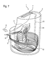
Figur 7- eine schematische Darstellung eines Sensors entsprechend der zweiten Ausführungsform, mit ebenfalls symbolisch darin dargestellter Gasstromführung im Inneren der Gasproben-Separiereinheit.
- FIGS. 1 and 2
- a gas sample separating unit for a sensor according to the invention for sensing particles in a gas stream as a sectional view in an oblique plan view (Figure 1) and in front view (Figure 2);
- FIG. 3
- an embodiment according to the figure 1 with a particle sensor arranged therein and symbolically represented by arrows flow conditions of the gas sample separating unit flowing gas stream;
- FIG. 4
- a further embodiment of a sensor for sensing particles in a gas stream in an oblique plan view of a sectional view;
- FIGS. 5 and 6
- two oblique plan views of the second embodiment in a closed view; and
- FIG. 7
- a schematic representation of a sensor according to the second embodiment, with also symbolically shown therein gas flow guide in the interior of the gas sample separating unit.
Die Figuren 1 bis 3 zeigen eine erste Ausführungsform eines Sensors 1 zur Sensierung von Partikeln in einem Gasstrom. Sie umfasst eine Gasproben-Separiereinheit 2 und eine von dieser zumindest teilweise umgebenen Partikelsensiereinheit 3. Diese Anordnung kann zur quantitativen Bestimmung von Partikeln in einen zu überwachenden Gasstrom von mobilen oder auch immobilen Verbrennungsvorrichtungen eingebracht werden. Zur Überwachung sind hierbei insbesondere Abgasstränge von Dieselmotoren aber auch andere Abgasstränge, wie z.B. die von Heizanlagen denkbar.FIGS. 1 to 3 show a first embodiment of a sensor 1 for sensing particles in a gas stream. It comprises a gas
Die Figur 1 zeigt eine Gasproben-Separiereinheit 2 in schräger Draufsicht als Schnittdarstellung, wie sie zur Erfassung von Partikeln in einem Gasstrom angeordnet werden kann.1 shows a gas
Um eine quantitative Aussage zu Partikeln bestimmter Größen und/oder Massen in dem zu überwachenden Gasstrom tätigen zu können, umfasst sie erfindungsgemäß entsprechend selektiv ausgebildete Partikel-Selektiermittel 4. Im vorliegenden Fall sind diese mechanisch ausgebildet.In order to be able to make a quantitative statement on particles of particular sizes and / or masses in the gas stream to be monitored, it comprises according to the invention correspondingly selectively formed particle-selecting
Ein erstes Selektiermittel 4 wird z.B. durch eine den freien Zugangsquerschnitt zur Partikelsensiereinheit 3 begrenzende Einlassöffnung 5 realisiert. In der Ausführungsform nach den Figuren 1 bis 3 ist diese in etwa parallel zu einer Längsachse 6 der Gasproben-Separiereinheit ausgebildet. Die Längsachse 6 verläuft in diesem Ausführungsbeispiel durch eine Auslassöffnung 7, für den die Gasproben-Separiereinheit 2 durchströmenden Teil des zu überwachenden Gasstromes. Für diese Ausführungsform ist es vorgesehen, dass mehrere Einlassöffnungen 5 an der Gasproben-Separiereinheit 2 ausgebildet und derart angeordnet sind, dass sie in etwa quer zu einer Strömungsrichtung des den Sensor 1 umströmenden Gasstroms 8 ausgerichtet sind.A first selection means 4 is for example by a free Access cross section to the
Der die Gasproben-Separiereinheit 2 durchströmende Teil des Gasstromes 9 trägt die in ihm enthaltenen Partikel entlang des durch die Pfeile 9 dargestellten Strömungsweges in Richtung zur Partikelsensiereinheit 3. Der Gasstrom 9 umströmt dabei die Partikelsensiereinheit 3 derart, dass sich die in ihm befindlichen Partikel auf der hier beispielhaft als Partikelsensiereinheit 3 dargestellten interdigitalen Elektrodenstruktur 10 ablagern können. Ebenfalls beispielhaft sind entlang des Strömungswegs des Gasstroms 9 und auf der Oberfläche der Partikelsensiereinheit 3 Partikel 11 dargestellt. Es ergeben sich daraus die Vorteile:
- reproduzierbare Strömungsrichtung und Geschwindigkeit je Motorbetriebspunkt;
- eindeutige Korrelation zwischen VAbgasströmung und Vam Sensorelement
- kontrollierte Strömungsbewegungen
- reproducible flow direction and speed per engine operating point;
- clear correlation between V exhaust flow and V at the sensor element
- controlled flow movements
Im Weiteren weist die Gasproben-Separiereinheit 2 Mittel zur Umlenkung des sie durchströmenden Teils des zu überwachenden Gasstroms in der Form von Durchlassöffnungen 12 auf, die in einer im Inneren der Gasproben-Separiereinheit 2 ausgebildeten Hülle angeordnet sind. Diese Hülle ist in der Form eines Innenrohres 13 der in dieser Ausführungsform als doppelwandiges Schutzrohr ausgebildeten Gasproben-Separiereinheit 2 realisiert. Die äußere Hülle schließt mit ihr einen Zwischenraum 16 ein, und wird durch das Außenrohr 14 definiert, in dem in einer stirnseitigen Umbördelung mehrere Einlassöffnungen 5 angeordnet sind.Furthermore, the gas
Ein weiteres Mittel zur Umlenkung des Teil-Gasstroms 9 stellen entlang dessen Verlaufs angeordnete Leit- bzw. Prallbleche 15 dar. Vorzugsweise sind diese im Umgebungsbereich von Durchlässen angeordnet, wie z.B. bei den Durchgangsöffnungen 12.A further means for deflecting the partial gas flow 9 represent along the course arranged baffles 15. Preferably, these are arranged in the vicinity of passages, such as. at the
Einerseits lenken sie den bereits einmal um etwa 90° umgelenkten Teil des Gasstromes 9 aus einer Längsströmrichtung in eine mit einer rotierenden Komponente beaufschlagten Strömungsrichtung im Inneren des Innenrohres 13 um. Andererseits bewirkt jede Umlenkung des Gasstroms eine Zentrifugalkraft auf die in ihm befindlichen Partikel und somit eine selektive Wirkung anhand der dabei auftretenden Querbeschleunigungen. Partikel mit zu großer Masse prallen dabei auf die Platte oder werden in einem anderen Wandbereich in einer der Einlassöffnung nachselektierenden Weise abgelagert.On the one hand, they divert the part of the gas flow 9, which has already been deflected once by about 90 °, from a longitudinal flow direction into a flow direction in the interior of the
Die Figur 4 zeigt eine zweite Ausführungsform eines Partikelsensors mit einer gegenüber der ersten Ausführungsform abgewandelten Gasproben-Separiereinheit 12. Für die gleichen Funktionen, wie in der ersten Ausführungsform beschrieben, sind auch hier die gleichen Bezugszeichen vergeben.FIG. 4 shows a second embodiment of a particle sensor with a gas
Diese Ausführungsform ist dazu vorgesehen, derart in den zu überwachenden Gasstrom 8 angeordnet zu werden, dass eine an ihm ausgebildete Einlassöffnung 5 direkt in der Strömungsrichtung des Gasstroms 8 angeordnet ist. Dazu ist die Einlassöffnung 5 radial zu einer Längsachse 6 dieser Ausführungsform der Gasproben-Separiereinheit 2 ausgerichtet angeordnet.This embodiment is intended to be arranged in the
Um eine besonders gute Fangeigenschaft für in dem zu überwachenden Gasstrom 8 befindliche Partikel 11 zur Verfügung stellen zu können, kann die Einlassöffnung 5 beispielsweise in der Form eines länglichen, günstige Strömungseigenschaften aufweisenden Schlitzes ausgebildet sein, der ebenfalls in einen Zwischenraum 16 zwischen dem Innenrohr 13 und dem Außenrohr 14 mündet. Dieser Zwischenraum 16 mündet seinerseits, ebenfalls wie in der ersten Ausführungsform, über eine Durchlassöffnung 12 in den Innenraum des Innenrohres 13. Dadurch ergeben sich die Vorteile:
- hohe Strömungsgeschwindigkeit;
- hohe Empfindlichkeit bei niedriger Partikelkonzentration;
- kontrollierte und definierte Sensorelementanströmung
- reproduzierbare und definierte Signalbildung;
- hohe Geschwindigkeit der Sonde.
- high flow rate;
- high sensitivity at low particle concentration;
- controlled and defined sensor element inflow
- reproducible and defined signal formation;
- high speed of the probe.
In der Figur 7 ist ein schematischer Verlauf des Gasstroms 9 dargestellt. Er tritt durch die Einlassöffnung 5 in den Zwischenraum 16 ein, und aus diesem durch die Durchlassöffnung in den Innenraum des Innenrohres 13. Darin umströmt er die Partikelsensiereinheit 3, auf der sich in ihm befindliche Partikel ablagern können. Zur besseren Übersicht wurde auf die Darstellung des weiteren Verlaufs des Gasstroms, hin zur Auslassöffnung 7, verzichtet.FIG. 7 shows a schematic profile of the gas flow 9. It enters through the
Claims (11)
Applications Claiming Priority (1)
| Application Number | Priority Date | Filing Date | Title |
|---|---|---|---|
| DE102006006112.8A DE102006006112B4 (en) | 2006-02-10 | 2006-02-10 | Particle sensor |
Publications (2)
| Publication Number | Publication Date |
|---|---|
| EP1818665A2 true EP1818665A2 (en) | 2007-08-15 |
| EP1818665A3 EP1818665A3 (en) | 2014-06-18 |
Family
ID=37910628
Family Applications (1)
| Application Number | Title | Priority Date | Filing Date |
|---|---|---|---|
| EP07100116.8A Withdrawn EP1818665A3 (en) | 2006-02-10 | 2007-01-04 | Particle sensor |
Country Status (2)
| Country | Link |
|---|---|
| EP (1) | EP1818665A3 (en) |
| DE (1) | DE102006006112B4 (en) |
Cited By (1)
| Publication number | Priority date | Publication date | Assignee | Title |
|---|---|---|---|---|
| AT513007A3 (en) * | 2013-09-25 | 2014-08-15 | Avl List Gmbh | Exhaust gas sampling probe |
Families Citing this family (9)
| Publication number | Priority date | Publication date | Assignee | Title |
|---|---|---|---|---|
| DE102006046837B4 (en) | 2006-10-02 | 2024-01-11 | Robert Bosch Gmbh | Method for operating a sensor for detecting particles in a gas stream |
| DE102013220890A1 (en) * | 2013-10-15 | 2015-04-16 | Continental Automotive Gmbh | soot sensor |
| DE102016213637B4 (en) * | 2016-07-26 | 2023-09-21 | Emisense Technologies Llc | Particle sensor with protection element against contamination |
| DE102016213641B4 (en) | 2016-07-26 | 2023-03-30 | Emisense Technologies Llc | Particle sensor with deflection element |
| DE102016224410B4 (en) | 2016-12-07 | 2023-09-28 | Emisense Technologies Llc | Sensor for use in an exhaust stream of an internal combustion engine and method for producing the same |
| KR20180065318A (en) | 2016-12-07 | 2018-06-18 | 현대자동차주식회사 | Chip type sensor for measuring particulate matter |
| DE102017204911A1 (en) * | 2017-03-23 | 2018-09-27 | Continental Automotive Gmbh | Method for testing a soot particle filter of a motor vehicle and sensor device and motor vehicle |
| DE102017215689B4 (en) | 2017-09-06 | 2023-01-05 | Emisense Technologies Llc | Particle sensor for an internal combustion engine |
| DE102017215798A1 (en) | 2017-09-07 | 2019-03-07 | Continental Automotive Gmbh | Particle sensor with deflecting element |
Citations (3)
| Publication number | Priority date | Publication date | Assignee | Title |
|---|---|---|---|---|
| US20040144645A1 (en) * | 2003-01-20 | 2004-07-29 | Kohei Yamada | Gas sensor with improved structure of protective cover |
| US20040259267A1 (en) * | 2003-05-15 | 2004-12-23 | The Regents Of The University Of California | Apparatus for particulate matter analysis |
| DE102004048597A1 (en) * | 2004-10-06 | 2006-04-13 | Robert Bosch Gmbh | Oxygen sensor for measuring the concentration or temperature of gas, comprises a sensor element in a housing, which is air tighten by a sealing arrangement between a cup shaped alumina parts, which is interlocked at each other |
Family Cites Families (18)
| Publication number | Priority date | Publication date | Assignee | Title |
|---|---|---|---|---|
| EP0458368B1 (en) * | 1984-04-02 | 1997-02-26 | Hitachi, Ltd. | Oxygen sensor |
| JPS61125758U (en) * | 1985-01-26 | 1986-08-07 | ||
| WO1992008127A1 (en) * | 1990-10-26 | 1992-05-14 | Robert Bosch Gmbh | Gas measurement probe, especially for determining the oxygen content in internal combustion engine exhaust gases |
| DE19628423C2 (en) * | 1996-03-06 | 1999-04-01 | Bosch Gmbh Robert | Gas sensor |
| JP3873390B2 (en) * | 1996-09-04 | 2007-01-24 | 株式会社デンソー | Oxygen sensor |
| JP3518796B2 (en) * | 1998-07-07 | 2004-04-12 | 日本特殊陶業株式会社 | Gas sensor |
| EP0974836B1 (en) * | 1998-07-13 | 2014-01-15 | Denso Corporation | Gas sensor having improved structure for installation of protective cover |
| JP3531859B2 (en) * | 1998-09-28 | 2004-05-31 | 株式会社デンソー | Gas sensor |
| DE19853841C2 (en) * | 1998-11-23 | 2001-04-12 | Victor Gheorghiu | Measuring probe and measuring method for the rapid detection of the particle concentration in flowing and still incombustible gases |
| JP3829026B2 (en) * | 1999-04-19 | 2006-10-04 | 日本碍子株式会社 | Gas sensor |
| EP1236998B1 (en) * | 2001-02-28 | 2006-09-13 | Denso Corporation | Rapid response gas sensor |
| DE10133384A1 (en) | 2001-07-10 | 2003-01-30 | Bosch Gmbh Robert | Particle detection sensor and method for checking its function |
| DE10244702A1 (en) | 2001-10-09 | 2003-05-08 | Bosch Gmbh Robert | Method for the detection of particles in a gas stream and sensor therefor |
| US7241370B2 (en) * | 2002-08-20 | 2007-07-10 | Ngk Spark Plug Co., Ltd. | Protective covers for gas sensor, gas sensor and gas sensor manufacturing method |
| JP4174004B2 (en) | 2003-03-31 | 2008-10-29 | 日本碍子株式会社 | Gas sensor |
| DE102004033958A1 (en) * | 2004-07-14 | 2006-02-09 | Robert Bosch Gmbh | probe |
| DE102005015103A1 (en) | 2004-09-30 | 2006-04-06 | Robert Bosch Gmbh | Particle sensor and method of operating the same |
| NL1028013C2 (en) | 2005-01-12 | 2006-07-17 | Stichting Energie | Method and assembly for determining soot particles in a gas stream. |
-
2006
- 2006-02-10 DE DE102006006112.8A patent/DE102006006112B4/en active Active
-
2007
- 2007-01-04 EP EP07100116.8A patent/EP1818665A3/en not_active Withdrawn
Patent Citations (3)
| Publication number | Priority date | Publication date | Assignee | Title |
|---|---|---|---|---|
| US20040144645A1 (en) * | 2003-01-20 | 2004-07-29 | Kohei Yamada | Gas sensor with improved structure of protective cover |
| US20040259267A1 (en) * | 2003-05-15 | 2004-12-23 | The Regents Of The University Of California | Apparatus for particulate matter analysis |
| DE102004048597A1 (en) * | 2004-10-06 | 2006-04-13 | Robert Bosch Gmbh | Oxygen sensor for measuring the concentration or temperature of gas, comprises a sensor element in a housing, which is air tighten by a sealing arrangement between a cup shaped alumina parts, which is interlocked at each other |
Cited By (2)
| Publication number | Priority date | Publication date | Assignee | Title |
|---|---|---|---|---|
| AT513007A3 (en) * | 2013-09-25 | 2014-08-15 | Avl List Gmbh | Exhaust gas sampling probe |
| AT513007B1 (en) * | 2013-09-25 | 2017-03-15 | Avl List Gmbh | Exhaust gas sampling probe |
Also Published As
| Publication number | Publication date |
|---|---|
| EP1818665A3 (en) | 2014-06-18 |
| DE102006006112B4 (en) | 2024-01-11 |
| DE102006006112A1 (en) | 2007-08-16 |
Similar Documents
| Publication | Publication Date | Title |
|---|---|---|
| DE102006006112B4 (en) | Particle sensor | |
| DE4107902C2 (en) | Device for in-line analysis of the particle size distribution in exhaust gases | |
| EP2029976B1 (en) | Mass flow sensor device with a flow guiding channel | |
| EP1502016B1 (en) | Device and method for determining a malfunction in a filter | |
| EP2270465B2 (en) | Process and apparatus for detecting, characterising and/or eliminating particles | |
| DE3200507C2 (en) | Intake duct for an internal combustion engine | |
| EP1563170B1 (en) | Method for recognition of the loading of a particle filter | |
| WO2001018498A9 (en) | Device for measuring at least one parameter of a medium that flows in a conduit | |
| EP1697687B1 (en) | Method for determining fluctuating fuel properties during the operation of a power plant | |
| DE102018203936B4 (en) | Exhaust system for an internal combustion engine and corresponding internal combustion engine | |
| EP3679341A1 (en) | Particle sensor for an internal combustion engine | |
| EP2005138B1 (en) | Sensor for detecting particles in a fluid and method for detecting particles in a fluid | |
| WO2021197957A1 (en) | Method and device for analysing particles of an aerosol | |
| DE102006032906B4 (en) | Apparatus and method for detecting and evaluating particles in a gas stream | |
| DE102007029945B4 (en) | Method for improving the cylinder-selective measurement of the lambda value in the exhaust gas of an internal combustion engine | |
| EP4134635B1 (en) | Determination of the flow rate of a flowing fluid | |
| DE102009054082A1 (en) | Measuring device, fresh air duct, fresh air system and flow guide element | |
| DE19958441A1 (en) | Analyzing IC engine exhaust comprises separating off partial gas current via by-pass, passing it through measuring section and feeding it back into main stream, speed of flow in by-pass being independent of that of main stream | |
| EP4092256A1 (en) | Exhaust gas system of a combustion engine | |
| EP2171426A1 (en) | Sensor, method and use thereof for detecting the size distribution of particles in a gas stream | |
| DE102019208869A1 (en) | Sensor arrangement for determining at least one exhaust gas parameter in an exhaust gas flow, and internal combustion engine with such a sensor arrangement | |
| DE202021104287U1 (en) | Determination of the flow of a flowing fluid | |
| DE112020002134T5 (en) | Device for detecting a physical quantity | |
| DE102019007211A1 (en) | Method for particle measurement in the exhaust gas of an internal combustion engine and particle measurement device | |
| DE102018217779A1 (en) | Air mass measuring device with flow guiding element |
Legal Events
| Date | Code | Title | Description |
|---|---|---|---|
| PUAI | Public reference made under article 153(3) epc to a published international application that has entered the european phase |
Free format text: ORIGINAL CODE: 0009012 |
|
| AK | Designated contracting states |
Kind code of ref document: A2 Designated state(s): AT BE BG CH CY CZ DE DK EE ES FI FR GB GR HU IE IS IT LI LT LU LV MC NL PL PT RO SE SI SK TR |
|
| AX | Request for extension of the european patent |
Extension state: AL BA HR MK YU |
|
| PUAL | Search report despatched |
Free format text: ORIGINAL CODE: 0009013 |
|
| AK | Designated contracting states |
Kind code of ref document: A3 Designated state(s): AT BE BG CH CY CZ DE DK EE ES FI FR GB GR HU IE IS IT LI LT LU LV MC NL PL PT RO SE SI SK TR |
|
| AX | Request for extension of the european patent |
Extension state: AL BA HR MK RS |
|
| RIC1 | Information provided on ipc code assigned before grant |
Ipc: G01N 27/407 20060101ALI20140512BHEP Ipc: G01N 15/02 20060101AFI20140512BHEP Ipc: G01N 1/22 20060101ALI20140512BHEP |
|
| 17P | Request for examination filed |
Effective date: 20141218 |
|
| RBV | Designated contracting states (corrected) |
Designated state(s): AT BE BG CH CY CZ DE DK EE ES FI FR GB GR HU IE IS IT LI LT LU LV MC NL PL PT RO SE SI SK TR |
|
| AKX | Designation fees paid |
Designated state(s): AT BE BG CH CY CZ DE DK EE ES FI FR GB GR HU IE IS IT LI LT LU LV MC NL PL PT RO SE SI SK TR |
|
| AXX | Extension fees paid |
Extension state: BA Extension state: HR Extension state: RS Extension state: AL Extension state: MK |
|
| 17Q | First examination report despatched |
Effective date: 20180227 |
|
| RAP1 | Party data changed (applicant data changed or rights of an application transferred) |
Owner name: ROBERT BOSCH GMBH |
|
| STAA | Information on the status of an ep patent application or granted ep patent |
Free format text: STATUS: THE APPLICATION IS DEEMED TO BE WITHDRAWN |
|
| 18D | Application deemed to be withdrawn |
Effective date: 20200616 |