EP1818244B1 - A device for operating a track tension wheel - Google Patents
A device for operating a track tension wheel Download PDFInfo
- Publication number
- EP1818244B1 EP1818244B1 EP07101455A EP07101455A EP1818244B1 EP 1818244 B1 EP1818244 B1 EP 1818244B1 EP 07101455 A EP07101455 A EP 07101455A EP 07101455 A EP07101455 A EP 07101455A EP 1818244 B1 EP1818244 B1 EP 1818244B1
- Authority
- EP
- European Patent Office
- Prior art keywords
- arm
- tension wheel
- pivot
- way
- drive device
- Prior art date
- Legal status (The legal status is an assumption and is not a legal conclusion. Google has not performed a legal analysis and makes no representation as to the accuracy of the status listed.)
- Not-in-force
Links
- 230000009471 action Effects 0.000 claims description 6
- 230000006835 compression Effects 0.000 claims description 2
- 238000007906 compression Methods 0.000 claims description 2
- 239000006096 absorbing agent Substances 0.000 description 1
- 230000003213 activating effect Effects 0.000 description 1
- 230000004913 activation Effects 0.000 description 1
- 230000008859 change Effects 0.000 description 1
- 230000003247 decreasing effect Effects 0.000 description 1
- 230000007246 mechanism Effects 0.000 description 1
- 230000002093 peripheral effect Effects 0.000 description 1
- 230000009467 reduction Effects 0.000 description 1
- 230000035939 shock Effects 0.000 description 1
Images


Classifications
-
- B—PERFORMING OPERATIONS; TRANSPORTING
- B62—LAND VEHICLES FOR TRAVELLING OTHERWISE THAN ON RAILS
- B62D—MOTOR VEHICLES; TRAILERS
- B62D55/00—Endless track vehicles
- B62D55/08—Endless track units; Parts thereof
- B62D55/30—Track-tensioning means
- B62D55/305—Track-tensioning means acting on pivotably mounted idlers
Definitions
- the invention relates to devices for operating a track tension wheel on a tracked vehicle, and relates more specifically to a device of the type that comprises a tension wheel arm that has an axis of rotation at a first end, around which the arm can be pivoted in relation to the vehicle by means of a first drive device, which tension wheel arm carries the tension wheel at its other end, via a rocker arm that is mounted on the tension wheel arm in such a way that it can pivot around a spindle, and a second drive device for changing the distance between the central axis of the tension wheel and the centre of rotation of the tension wheel arm by pivoting the rocker arm in relation to the tension wheel arm, in order thereby to adjust the tension of, or alternatively to replace, the vehicle's drive track that is running over the tension wheel, with the first drive device having a first end that engages with the tension wheel arm at a distance from the centre of rotation of the tension wheel arm in such a way that it can pivot, and a second end that is connected to a first fixing in such a way that
- a device of essentially the type described in the introduction that makes this possible is already known through FR 1 401 309 (see Figures 6 and 7 ).
- This device is not designed to be able to achieve an automatic tensioning of the drive track during the final phase of the lowering of the tension wheel arm.
- the operating device for the tension wheel is bulky and can be easily damaged by external objects.
- the operating cylinder for pivoting the tension wheel arm upwards and downwards is permanently attached to the vehicle in such a way that it does not allow rapid springing movements of the tension wheel arm, when, for example, the tension wheel drives over a projecting object on the ground.
- a device for operating a track tension wheel on a tracked vehicle, which device has a tension wheel arm that can be adjusted telescopically in length, and achieves an automatic lengthening of the arm when this is lowered, in order at the same time to obtain a required tensioning of the associated drive track that runs around the tension wheel.
- the tension wheel arm is operated by two hydraulic cylinders that are mounted on the vehicle itself in such a way that they can pivot.
- the mechanical connections between the hydraulic cylinders and the arm and between the hydraulic cylinders and the eccentric mechanism can be exposed to external forces, in addition to which seals need to be arranged to protect the cylinders from the ingress of dirt.
- the automatic lengthening of the arm when it is pivoted down can create too strong a tension in the drive track in a horizontal position of the arm.
- one of the two cylinders can act as a shock absorber, by oil in the cylinder being allowed to flow through an associated regulator.
- a primary object of the present invention is to achieve an operating device for a track tension wheel on a tracked vehicle, where the operating device is very compact and makes it possible to incorporate the drive devices (the hydraulic cylinders) in the tension wheel arm in a way that protects them, with the operating device, in addition, making possible an automatic changing of the distance between the centre of the tension wheel and the centre of rotation of the tension wheel arm during pivoting upwards and downwards of the tension wheel arm, only over a lower pivoting range, while the distance between centres remains essentially constant over an upper pivoting range, while, at the same time, it is possible to prevent the drive track from being tensioned too much in an essentially horizontal position of the tension wheel arm.
- the operating device according to the invention has the characteristics that are described in Claim 1.
- An additional object of the invention is to achieve an operating device of the type in question that enables there to be a rapid inward and outward springing movement of the tension wheel arm.
- the first drive device for pivoting the tension wheel arm upwards or downwards preferably a hydraulic cylinder
- the first drive device can be urged by a mechanical spring towards a first position in a non-rigid way, in which position the tension wheel arm assumes a lowered position, while the first drive device can be moved in its entirety and in a locked state towards a position that is displaced backward in relation to the first position, against the action of the tensioning force of the spring.
- the first drive device can be compressed in a non-rigid way by the action of a hydraulic or pneumatic spring unit, that comprises a pressure accumulator connected to the drive device.
- a tension wheel arm according to the invention is designated in general by 10 in the drawings.
- Such an arm 10 is mounted in such a way that it can pivot around a centre of rotation 12 on each side of a rear part of a tracked vehicle (not shown) in order to tension an endless drive track on the left and right sides of the vehicle by means of a tension wheel (not shown) mounted on the outer end of the arm, and also to move the tension wheel between a raised position and a lowered position in the track adjusting arrangement to obtain different running characteristics for the vehicle depending upon the surface on which the vehicle is being driven.
- Each tension wheel arm 10 comprises a tension wheel unit in the form of a rigid housing 14 that can house most of the components of the tension wheel arm 10.
- a hub part 16 of the housing 14 is mounted in such a way that it can pivot around the central axis 12 on a fixing designated in general by 18, that is designed to be permanently attached to the respective side of the rear part of the tracked vehicle.
- a rocker arm 20 (see Figure 4 ) that is mounted in such a way that it can pivot around an axis of rotation 22 through a spindle 24.
- the rocker arm 20 On its outer end, the rocker arm 20 carries a tension wheel fixing 26 that can rotate around an axis of rotation 25, to which fixing a track tension wheel (not shown) is mounted.
- the tension wheel arm 10 has a drive device mounted inside the housing 14 that acts in a linear direction, here in the form of a hydraulic cylinder 28 (below called the “tensioning cylinder”), that has a piston rod 30 that is connected to a crank 32 in such a way that it can pivot, which crank is in turn connected to the rocker arm 20 in such a way that it moves the rocker arm, by means of the spindle 24 that can rotate around the axis of rotation 22.
- a drive device mounted inside the housing 14 that acts in a linear direction, here in the form of a hydraulic cylinder 28 (below called the “tensioning cylinder”), that has a piston rod 30 that is connected to a crank 32 in such a way that it can pivot, which crank is in turn connected to the rocker arm 20 in such a way that it moves the rocker arm, by means of the spindle 24 that can rotate around the axis of rotation 22.
- the tensioning cylinder 28 is attached at 34 to an outer end of a link arm 36, arranged to make contact with a retainer (not shown) at the second fixing (18), in such way that it can pivot, an inner end of which link arm is preferably mounted on the fixing 18 in such a way that it can pivot around the axis of rotation 12 of the arm 10.
- the link arm 36 is preferably designed as two parallel link arms, that link the fixing 18 and the cylinder fixing at 34.
- the piston rod 30 can thus pivot the tension wheel mounted on the fixing 26, via the crank 32 and the rocker arm 20, in a direction outwards away from the axis of rotation 12 of the arm 10 ( Figure 1 ) to tension the drive track, or in a direction inwards towards the axis of rotation 12 ( Figure 7 ) to reduce the tension in the drive track or to enable the drive track to be replaced.
- an additional drive device that acts in a linear direction in the form of a hydraulic cylinder 38 (below called a "pivoting cylinder") is arranged inside the housing 14 of the arm 10.
- a hydraulic cylinder 38 (below called a "pivoting cylinder")
- One end of the pivoting cylinder 38 is attached at 40 to one end of a link arm 42 in such a way that it can pivot, the other end of the link arm being attached to a torsion rod 44 in such a way that it can pivot, the opposite end 46 of the torsion rod ( Figure 4 ) being designed to be permanently attached to the vehicle.
- This link arm 42 is also preferably designed as two parallel link arms, that link the cylinder fixing at 40 and the fixing 18.
- the pivoting cylinder 38 has a piston rod 48, the outer end of which engages, in such a way that it can pivot, with a part that is attached to the housing 14 at a distance from the axis of rotation 12 of the arm.
- This part can suitably consist of a spindle 24 that connects the crank 32 to the rocker arm 20 in such a way that the crank moves the rocker arm.
- the tensioning cylinder 28 thereby rotates around the point 34, while at the same time it is kept inactivated, that is locked so that the cylinder part 28 and the piston rod 30 do not move in relation to each other, which, due to the point of attachment 34 of the tensioning cylinder 28 not lying at the centre of rotation 12 of the arm, means that the distance between the axis of rotation 12 of the arm 10 and the central axis 25 of the tension wheel is decreased somewhat, with the result that a particular required reduction of the track tension takes place during this pivoting-upward phase.
- the track tension wheel When driving the tracked vehicle on a relatively soft surface, the track tension wheel is set in its lower operating position according to Figure 1 .
- the pivoting cylinder 38 and the tensioning cylinder 28 are normally kept hydraulically locked, the pivoting cylinder 38 can be pivoted around the centre of rotation of the torsion rod 44 via the link arm 42 in order to allow rapid individual inward and outward springing movements of the tension wheel arm 10 when driving over uneven ground or over projecting objects.
- Figure 5 shows a partially sprung-inward position of the arm 10
- Figure 6 shows a maximally sprung-inward position.
- a springing inward of the arm 10 thus takes place against the action of the spring tensioning force of the torsion rod 44 on the pivoting cylinder 38.
- This spring force is, however, sufficiently large to enable the pivoting cylinder 38 to remain essentially stationary in a retracted end position in the driving direction during a pivoting downward or upward of the arm 10 as shown in Figures 1-3 and thereby to withstand the torque that the drive track exerts on the link arm 42 via the rocker arm 20, the piston rod 48 and the cylinder 38.
- the pivoting cylinder 38 can be constructed so that it can be compressed in a non-rigid way, such as a hydraulic or pneumatic spring unit, that can comprise an arrangement with a pressure-controlled overflow valve (not shown) in combination with a hydraulic/pneumatic accumulator 52, as shown schematically in Figure 8 . Accordingly, the link arm 42 can be omitted and the pivoting cylinder 38, 48 can be attached to a stationary point on the fixing 18 in such a way that it can pivot.
- hydraulic cylinders 28 and 38 are shown in the described embodiment as drive devices for changing the length and angular position of the tension wheel arm 10, it is of course possible within the framework of the invention to utilize other linear or rotating drive devices to achieve an equivalent operating function. Examples of these can be pneumatic cylinders, ball screws, electrical or hydraulic motors with toothed wheel gears or the like.
- torsion rod 44 and the link arm 42 for tensioning the pivoting cylinder 38 towards an end position, in which the tension wheel arm 10 can pivot between a raised position and a lowered position by activation of the pivoting cylinder 38.
- a suitably designed compression spring could be arranged to act on the end of the pivoting cylinder 38 at 40 and thereby have an equivalent function to make possible rapid inward and outward springing movements of the tension wheel arm 10.
Landscapes
- Engineering & Computer Science (AREA)
- Chemical & Material Sciences (AREA)
- Combustion & Propulsion (AREA)
- Transportation (AREA)
- Mechanical Engineering (AREA)
- Devices For Conveying Motion By Means Of Endless Flexible Members (AREA)
- Vehicle Body Suspensions (AREA)
- Valve-Gear Or Valve Arrangements (AREA)
- Transmission Devices (AREA)
Abstract
Description
- The invention relates to devices for operating a track tension wheel on a tracked vehicle, and relates more specifically to a device of the type that comprises a tension wheel arm that has an axis of rotation at a first end, around which the arm can be pivoted in relation to the vehicle by means of a first drive device, which tension wheel arm carries the tension wheel at its other end, via a rocker arm that is mounted on the tension wheel arm in such a way that it can pivot around a spindle, and a second drive device for changing the distance between the central axis of the tension wheel and the centre of rotation of the tension wheel arm by pivoting the rocker arm in relation to the tension wheel arm, in order thereby to adjust the tension of, or alternatively to replace, the vehicle's drive track that is running over the tension wheel, with the first drive device having a first end that engages with the tension wheel arm at a distance from the centre of rotation of the tension wheel arm in such a way that it can pivot, and a second end that is connected to a first fixing in such a way that it can pivot, while the second drive device has a first end that is connected in such a way that it can pivot to a part that is connected to the rocker arm.
- In order to change and optimize the driving characteristics of a tracked vehicle to suit the surface upon which it is being driven, varying the vertical position of the tension wheel on the tracked vehicle between an upper position, in which the vehicle can be driven on a hard firm surface, and a lowered position, in which the vehicle can be driven on a soft yielding surface such as deep snow, soft ground or marshland, has previously been proposed. At the same time, it is desirable to keep the track tension somewhat lower when the tension wheel is raised, in order to have less wear on the track when driving on a hard surface, and to keep the track tension increased somewhat when the tension wheel is lowered, in order to reduce the specific ground pressure when driving on a soft surface.
- A device of essentially the type described in the introduction that makes this possible is already known through
FR 1 401 309 Figures 6 and7 ). This device is not designed to be able to achieve an automatic tensioning of the drive track during the final phase of the lowering of the tension wheel arm. As a result of its design, the operating device for the tension wheel is bulky and can be easily damaged by external objects. In addition, on this device, the operating cylinder for pivoting the tension wheel arm upwards and downwards is permanently attached to the vehicle in such a way that it does not allow rapid springing movements of the tension wheel arm, when, for example, the tension wheel drives over a projecting object on the ground. - In
SE 0301046-9 SE 525 073 C - A primary object of the present invention is to achieve an operating device for a track tension wheel on a tracked vehicle, where the operating device is very compact and makes it possible to incorporate the drive devices (the hydraulic cylinders) in the tension wheel arm in a way that protects them, with the operating device, in addition, making possible an automatic changing of the distance between the centre of the tension wheel and the centre of rotation of the tension wheel arm during pivoting upwards and downwards of the tension wheel arm, only over a lower pivoting range, while the distance between centres remains essentially constant over an upper pivoting range, while, at the same time, it is possible to prevent the drive track from being tensioned too much in an essentially horizontal position of the tension wheel arm. For this purpose, the operating device according to the invention has the characteristics that are described in Claim 1.
- An additional object of the invention is to achieve an operating device of the type in question that enables there to be a rapid inward and outward springing movement of the tension wheel arm. For this purpose, the first drive device for pivoting the tension wheel arm upwards or downwards, preferably a hydraulic cylinder, can be urged by a mechanical spring towards a first position in a non-rigid way, in which position the tension wheel arm assumes a lowered position, while the first drive device can be moved in its entirety and in a locked state towards a position that is displaced backward in relation to the first position, against the action of the tensioning force of the spring. Alternatively, the first drive device can be compressed in a non-rigid way by the action of a hydraulic or pneumatic spring unit, that comprises a pressure accumulator connected to the drive device.
- Additional characteristics and specific components of the device according to the invention are described in the subsidiary claims and are apparent from the following detailed description, with reference to the attached drawings.
-
-
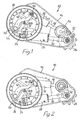
Figure 1 is a side view of a tension wheel arm according to the invention in a fully lowered position and with the tension wheel projected maximally from the centre of rotation; -
Figure 2 is a side view of the tension wheel arm according to the invention in a middle position; -
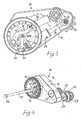
Figure 3 is a side view of the tension wheel arm according to the invention in a fully raised position; -
Figure 4 is a perspective view of the tension wheel arm according to the invention, viewed from the inside of the arm; -
Figure 5 is a side view of the tension wheel arm according to the invention in a partially sprung-inward position; -
Figure 6 is a side view of the tension wheel arm according to the invention in a maximally sprung-inward position; -
Figure 7 is a side view of the tension wheel arm according to the invention in a position in which the tension wheel is maximally retracted towards the centre of rotation of the tension wheel arm; and -
Figure 8 is a side view of a tension wheel arm according to a second embodiment of the invention in a lowered position. - A tension wheel arm according to the invention is designated in general by 10 in the drawings. Such an
arm 10 is mounted in such a way that it can pivot around a centre ofrotation 12 on each side of a rear part of a tracked vehicle (not shown) in order to tension an endless drive track on the left and right sides of the vehicle by means of a tension wheel (not shown) mounted on the outer end of the arm, and also to move the tension wheel between a raised position and a lowered position in the track adjusting arrangement to obtain different running characteristics for the vehicle depending upon the surface on which the vehicle is being driven. - Each
tension wheel arm 10 comprises a tension wheel unit in the form of arigid housing 14 that can house most of the components of thetension wheel arm 10. Ahub part 16 of thehousing 14 is mounted in such a way that it can pivot around thecentral axis 12 on a fixing designated in general by 18, that is designed to be permanently attached to the respective side of the rear part of the tracked vehicle. At an outer end of the housing 14 (the arm 10), there is a rocker arm 20 (seeFigure 4 ) that is mounted in such a way that it can pivot around an axis ofrotation 22 through aspindle 24. On its outer end, therocker arm 20 carries a tension wheel fixing 26 that can rotate around an axis of rotation 25, to which fixing a track tension wheel (not shown) is mounted. - In order to be able to adjust the tension of the drive track while the vehicle is stationary or during operation of the vehicle, and to make it possible to replace the drive track, it must be possible to move the tension wheel in such a way that the distance from the centre of the tension wheel to the axis of
rotation 12 of the arm 10 (the housing 14) can be adjusted. For this purpose, thetension wheel arm 10 has a drive device mounted inside thehousing 14 that acts in a linear direction, here in the form of a hydraulic cylinder 28 (below called the "tensioning cylinder"), that has apiston rod 30 that is connected to acrank 32 in such a way that it can pivot, which crank is in turn connected to therocker arm 20 in such a way that it moves the rocker arm, by means of thespindle 24 that can rotate around the axis ofrotation 22. The tensioningcylinder 28 is attached at 34 to an outer end of alink arm 36, arranged to make contact with a retainer (not shown) at the second fixing (18), in such way that it can pivot, an inner end of which link arm is preferably mounted on thefixing 18 in such a way that it can pivot around the axis ofrotation 12 of thearm 10. Thelink arm 36 is preferably designed as two parallel link arms, that link thefixing 18 and the cylinder fixing at 34. By activating the tensioningcylinder 28, thepiston rod 30 can thus pivot the tension wheel mounted on thefixing 26, via thecrank 32 and therocker arm 20, in a direction outwards away from the axis ofrotation 12 of the arm 10 (Figure 1 ) to tension the drive track, or in a direction inwards towards the axis of rotation 12 (Figure 7 ) to reduce the tension in the drive track or to enable the drive track to be replaced. - In addition, in order to be able to pivot the
tension wheel arm 10 around the axis ofrotation 12 between a lowered position (Figure 1 ) and a raised position (Figure 3 ) to suit the surface upon which the vehicle is being driven, an additional drive device that acts in a linear direction in the form of a hydraulic cylinder 38 (below called a "pivoting cylinder") is arranged inside thehousing 14 of thearm 10. One end of the pivotingcylinder 38 is attached at 40 to one end of alink arm 42 in such a way that it can pivot, the other end of the link arm being attached to atorsion rod 44 in such a way that it can pivot, theopposite end 46 of the torsion rod (Figure 4 ) being designed to be permanently attached to the vehicle. Thislink arm 42 is also preferably designed as two parallel link arms, that link the cylinder fixing at 40 and thefixing 18. The pivotingcylinder 38 has apiston rod 48, the outer end of which engages, in such a way that it can pivot, with a part that is attached to thehousing 14 at a distance from the axis ofrotation 12 of the arm. This part can suitably consist of aspindle 24 that connects thecrank 32 to therocker arm 20 in such a way that the crank moves the rocker arm. - As shown in
Figure 1 , on the inside of thehub 16 of thehousing 14 there is alug 50 that, in the fully lowered position of thearm 10, is at a distance in the peripheral direction from a radially outer end of thelink arm 36. When the pivotingcylinder 38 is activated in an initial upward rotation of thearm 10 from the position inFigure 1 , thepiston rod 48 is retracted into thecylinder 38, whereupon thelug 50 moves in a direction towards the outer end of thelink arm 36. The tensioningcylinder 28 thereby rotates around thepoint 34, while at the same time it is kept inactivated, that is locked so that thecylinder part 28 and thepiston rod 30 do not move in relation to each other, which, due to the point ofattachment 34 of thetensioning cylinder 28 not lying at the centre ofrotation 12 of the arm, means that the distance between the axis ofrotation 12 of thearm 10 and the central axis 25 of the tension wheel is decreased somewhat, with the result that a particular required reduction of the track tension takes place during this pivoting-upward phase. As a result of thelug 50 coming into contact with the outer end of the link arm 36 (seeFigure 2 ), the whole tensioningcylinder 28 is caused to rotate around the axis ofrotation 12 of thelink arm 36 and of thetension wheel arm 10, which means that during the continued upward rotation of thearm 10 to the upper end position as shown inFigure 3 , the distance between the centre 25 of the tension wheel and the centre ofrotation 12 of thearm 10 is kept constant. Depending upon the position of the axis ofrotation 12 of thearm 10 in relation to the upper and lower running parts of the vehicle's drive track, the tension of the respective drive tracks can be kept within the required values, when the tension wheel moves between its upper and lower end positions. - When driving the tracked vehicle on a relatively soft surface, the track tension wheel is set in its lower operating position according to
Figure 1 . In this operating position, when the pivotingcylinder 38 and the tensioningcylinder 28 are normally kept hydraulically locked, the pivotingcylinder 38 can be pivoted around the centre of rotation of thetorsion rod 44 via thelink arm 42 in order to allow rapid individual inward and outward springing movements of thetension wheel arm 10 when driving over uneven ground or over projecting objects. This is apparent by a comparison betweenFigure 5 , that shows a partially sprung-inward position of thearm 10, andFigure 6 that shows a maximally sprung-inward position. A springing inward of thearm 10 thus takes place against the action of the spring tensioning force of thetorsion rod 44 on the pivotingcylinder 38. This spring force is, however, sufficiently large to enable the pivotingcylinder 38 to remain essentially stationary in a retracted end position in the driving direction during a pivoting downward or upward of thearm 10 as shown inFigures 1-3 and thereby to withstand the torque that the drive track exerts on thelink arm 42 via therocker arm 20, thepiston rod 48 and thecylinder 38. - Due to the non-rigid attachment of the pivoting
cylinder 38 in relation to the vehicle and thetension wheel arm 10 by means of thetorsion rod 44 and thelink arm 42, rapid inward and outward springing movements of thearm 10 are made possible. In addition, the attachment of the tensioningcylinder 28 to thelink arm 36 and the central mounting of this in thefixing 18 on thearm 10 and the engagement between thelug 50 and the outer end of thelink arm 36 that brings about a rotation during a part of the pivoting movement of thearm 10 around theaxis 12, result in both a constant distance and changes to the distance between the axis ofrotation 12 of the arm and the central axis 25 of the tension wheel in such a way that this distance between centres is increased during a later phase of the lowering movement or reduced during an initial phase of an upward pivoting movement of thetension wheel arm 10. By this means, it is thus possible to achieve a required automatic tensioning of the vehicle's drive track during the later part of the lowering of thearm 10. - As an alternative solution for making possible rapid inward and outward springing movements of the
tension wheel arm 10, instead of the mechanical tensioning by means of atorsion spring 44 or the like, where the whole locked pivotingcylinder pivoting link arm 42, the pivotingcylinder 38 can be constructed so that it can be compressed in a non-rigid way, such as a hydraulic or pneumatic spring unit, that can comprise an arrangement with a pressure-controlled overflow valve (not shown) in combination with a hydraulic/pneumatic accumulator 52, as shown schematically inFigure 8 . Accordingly, thelink arm 42 can be omitted and the pivotingcylinder fixing 18 in such a way that it can pivot. - By means of the invention, a very compact design of the
tension wheel arm 10 is achieved, in which the drive devices oroperating cylinders rigid housing 14 of thearm 10 in such a way that they are protected. - Even though the
hydraulic cylinders tension wheel arm 10, it is of course possible within the framework of the invention to utilize other linear or rotating drive devices to achieve an equivalent operating function. Examples of these can be pneumatic cylinders, ball screws, electrical or hydraulic motors with toothed wheel gears or the like. - In addition, other mechanical spring devices can be utilized instead of the
torsion rod 44 and thelink arm 42 for tensioning the pivotingcylinder 38 towards an end position, in which thetension wheel arm 10 can pivot between a raised position and a lowered position by activation of the pivotingcylinder 38. For example, a suitably designed compression spring could be arranged to act on the end of the pivotingcylinder 38 at 40 and thereby have an equivalent function to make possible rapid inward and outward springing movements of thetension wheel arm 10.
Claims (14)
- Device for operating a track tension wheel on a tracked vehicle, comprising a tension wheel arm (10) that has an axis of rotation (12) at a first end, around which the arm (10) can be pivoted in relation to the vehicle by means of a first drive device (38, 48), and which tension wheel arm carries the tension wheel at its other end, via a rocker arm (20) that is mounted on the tension wheel arm (10) in such a way that it can pivot around a spindle (24), and a second drive device (28, 30) for changing the distance between the central axis (25) of the tension wheel and the centre of rotation (12) of the tension wheel arm by pivoting the rocker arm (20) in relation to the tension wheel arm (10), in order thereby to adjust the tension of, or alternatively to replace, the vehicle's drive track that is running over the tension wheel, with the first drive device (38, 48) having a first end that engages with the tension wheel arm (10) at a distance from the centre of rotation (12) of the tension wheel arm in such a way that it can pivot, and a second end that is connected to a first fixing in such a way that it can pivot, while the second drive device (28, 30) has a first end that is connected in such a way that it can pivot to a part (32) that is connected to the rocker arm (20), characterized in that the other end of the second drive device (28, 30) is connected (at 34) to a first pivoting link arm (36) in such a way that it can pivot, which pivot arm has a first end that is connected to a second fixing (18) in such a way that it can pivot, which fixing is designed to be attached to the vehicle; in that the first link arm (36) is arranged, in a first position of this, to make contact with a retainer at the second fixing (18), in order to allow the second drive device (28, 30) to pivot around its connection at (34) to the first link arm (36) in a first phase of the pivoting or springing upward movement of the tension wheel arm (10) from a fully lowered position and in that a lug (50) on the tension wheel arm (10) is arranged to engage with the first link arm (36) in a second continued phase of the pivoting or springing upward movement of the tension wheel arm, to cause the second drive device (28, 30) to pivot around the connection (at 12) of the first link arm (36) to the second fixing (18) during the continued pivoting or springing upward movement of the tension wheel arm (10).
- Device according to Claim 1, characterized in that the first end of the first link arm (36) is connected to the second fixing (18) at the axis of rotation (12) of the tension wheel arm (10) in such a way that it can pivot.
- Device according to Claim 2, characterized in that the second fixing (18) is located inside a hub part (16) of the tension wheel arm (10).
- Device according to any one of Claims 1-3, characterized in that the first end of the second drive device (28, 30) is connected to a crank (32) in such a way that it can pivot, which crank is rigidly connected to the spindle (24) that carries the rocker arm (20).
- Device according to any one of Claims 1-4, characterized in that the first drive device (38, 48) is arranged to allow an inward and outward springing movement of the tension wheel arm (10).
- Device according to Claim 5, characterized in that the first drive device (38, 48) is urged by a mechanical spring (44) towards a first position in a non-rigid way, in which position the tension wheel arm (10) assumes a lowered position, and in that the first drive device (38, 48) can be moved in its entirety and in a locked state towards a position that is displaced backward in relation to the first position, against the action of the tensioning force of the spring (44).
- Device according to Claim 6, characterized in that the second end of the first drive device (38, 48) is connected to the first fixing through a second pivoting link arm (42) in such a way that it can pivot.
- Device according to Claim 7, characterized in that the second link arm (42) has a first end that is connected (at 40) to the second end of the first drive device (38, 48) in such a way that it can pivot, and a second end that is connected to the first fixing in such a way that it can pivot.
- Device according to Claim 8, characterized in that the mechanical spring consists of a torsion rod (44) connected to the second end of the second link arm (42), which torsion rod is arranged to be attached to a fixing on the vehicle.
- Device according to any one of Claims 7-9, characterized in that the second link arm (42) is designed in such a way that its two ends are located at essentially diametrically opposite sides of the axis of rotation (12) of the tension wheel arm (10).
- Device according to any one of Claims 1-10, characterized in that the first and second drive devices (38, 48 and 28, 30) consist of hydraulic compression cylinders.
- Device according to Claim 11 in combination with Claim 5, characterized in that the first drive device (38, 48) can be compressed in a non-rigid way by the action of a hydraulic or pneumatic spring unit, that comprises a pressure accumulator (52) connected to the drive device (38, 48).
- Device according to any one of Claims 1-12, characterized in that the first end of the first drive device (38, 48) is connected to the spindle (24) in such a way that it can pivot.
- Device according to any one of Claims 1-13, characterized in that the tension wheel arm (10) is designed with a self-supporting housing (14) in which the first and the second drive devices (38, 48 and 28, 30) are contained and arranged essentially overlapping each other.
Applications Claiming Priority (1)
| Application Number | Priority Date | Filing Date | Title |
|---|---|---|---|
| SE0600274A SE529600C2 (en) | 2006-02-08 | 2006-02-08 | Tension wheel device |
Publications (3)
| Publication Number | Publication Date |
|---|---|
| EP1818244A2 EP1818244A2 (en) | 2007-08-15 |
| EP1818244A3 EP1818244A3 (en) | 2008-06-25 |
| EP1818244B1 true EP1818244B1 (en) | 2011-03-23 |
Family
ID=37989133
Family Applications (1)
| Application Number | Title | Priority Date | Filing Date |
|---|---|---|---|
| EP07101455A Not-in-force EP1818244B1 (en) | 2006-02-08 | 2007-01-31 | A device for operating a track tension wheel |
Country Status (8)
| Country | Link |
|---|---|
| US (1) | US7597411B2 (en) |
| EP (1) | EP1818244B1 (en) |
| AT (1) | ATE502840T1 (en) |
| DE (1) | DE602007013304D1 (en) |
| ES (1) | ES2363376T3 (en) |
| NO (1) | NO337953B1 (en) |
| SE (1) | SE529600C2 (en) |
| SG (1) | SG135094A1 (en) |
Families Citing this family (5)
| Publication number | Priority date | Publication date | Assignee | Title |
|---|---|---|---|---|
| SE532710C2 (en) * | 2008-12-16 | 2010-03-23 | Bae Systems Haegglunds Ab | Device for operating a tire tire wheel of a tire vehicle |
| DE102010022296A1 (en) * | 2010-05-31 | 2011-12-01 | Rheinmetall Landsysteme Gmbh | Device for damping vibrations in a tracked or tracked vehicle |
| EP3165432B1 (en) * | 2015-11-05 | 2019-06-19 | AGCO Corporation | Track system slack adjuster for tracked vehicle |
| US11919585B2 (en) * | 2019-07-15 | 2024-03-05 | Deere & Company | Track tension control |
| CN111516769B (en) * | 2020-05-12 | 2023-11-17 | 三一重机有限公司 | Crawler tensioners and crawler construction machinery |
Family Cites Families (11)
| Publication number | Priority date | Publication date | Assignee | Title |
|---|---|---|---|---|
| US2843431A (en) | 1956-12-28 | 1958-07-15 | John M Beaufort | Hydraulic track tensioning device |
| DK103654A (en) | 1960-11-26 | |||
| FR1401309A (en) | 1964-04-20 | 1965-06-04 | Creusot Forges Ateliers | Tracked vehicle with lengthwise and vertically adjustable tension pulleys |
| US4227748A (en) * | 1978-05-26 | 1980-10-14 | Caterpillar Tractor Co. | Track tensioning apparatus |
| FR2619070B1 (en) * | 1987-08-07 | 1991-09-06 | Colmant Cuvelier | TENSIONING DEVICE FOR THE FLEXIBLE OR ARTICULATED ELEMENT OF A TRANSMISSION OR BEARING SYSTEM |
| US5293948A (en) * | 1992-09-25 | 1994-03-15 | Caterpillar Inc. | Undercarriage assembly for a vehicle |
| US5316381A (en) | 1992-11-13 | 1994-05-31 | Deere & Company | Tensioning and suspension system for a tracked vehicle |
| DE19743494C2 (en) * | 1997-10-01 | 1999-07-22 | Intertractor Zweigniederlassun | Drive arrangement for caterpillar vehicles |
| SE508171C2 (en) * | 1997-10-03 | 1998-09-07 | Haegglunds Vehicle Ab | Band tensioning device for belt-driven motor photon |
| US6273530B1 (en) | 2000-01-06 | 2001-08-14 | Deere & Company | Toe-in/toe-out adjustment mechanism |
| SE525073C2 (en) | 2003-04-09 | 2004-11-23 | Alvis Haegglunds Ab | Device for operating a tension wheel of a tracked vehicle |
-
2006
- 2006-02-08 SE SE0600274A patent/SE529600C2/en not_active IP Right Cessation
-
2007
- 2007-01-23 SG SG200700521-8A patent/SG135094A1/en unknown
- 2007-01-30 US US11/699,633 patent/US7597411B2/en not_active Expired - Fee Related
- 2007-01-31 DE DE602007013304T patent/DE602007013304D1/en active Active
- 2007-01-31 AT AT07101455T patent/ATE502840T1/en active
- 2007-01-31 ES ES07101455T patent/ES2363376T3/en active Active
- 2007-01-31 EP EP07101455A patent/EP1818244B1/en not_active Not-in-force
- 2007-02-05 NO NO20070642A patent/NO337953B1/en not_active IP Right Cessation
Also Published As
| Publication number | Publication date |
|---|---|
| DE602007013304D1 (en) | 2011-05-05 |
| EP1818244A3 (en) | 2008-06-25 |
| NO337953B1 (en) | 2016-07-18 |
| SG135094A1 (en) | 2007-09-28 |
| SE529600C2 (en) | 2007-10-02 |
| SE0600274L (en) | 2007-08-09 |
| NO20070642L (en) | 2007-08-09 |
| ATE502840T1 (en) | 2011-04-15 |
| US7597411B2 (en) | 2009-10-06 |
| US20070182246A1 (en) | 2007-08-09 |
| EP1818244A2 (en) | 2007-08-15 |
| ES2363376T3 (en) | 2011-08-02 |
Similar Documents
| Publication | Publication Date | Title |
|---|---|---|
| US7597411B2 (en) | Device for operating a track tension wheel | |
| AU2002249471B2 (en) | Vehicle with retractable wheel | |
| KR102554918B1 (en) | Suspension apparatus able to adjusting vehucle height | |
| EP2370309B1 (en) | Arrangement for controlling a track tension wheel of a tracked vehicle | |
| AU2002249471A1 (en) | Vehicle with retractable wheel | |
| CN110405717B (en) | Universal walking mechanism and method for industrial robot | |
| KR20100019759A (en) | Active roll control system | |
| US11364761B2 (en) | Vehicle suspension device | |
| RU2681821C2 (en) | Civilian tracked vehicle | |
| KR102554919B1 (en) | Suspension apparatus able to adjusting vehucle height | |
| CN118651325B (en) | A shock-absorbing contoured wheel component assembly for an agricultural machinery crawler chassis | |
| JP5894484B2 (en) | Suspension device | |
| EP1466816B1 (en) | Device for manoeuvring a tension wheel of a tracked vehicle | |
| CN215043653U (en) | Bottom is equipped with descending bradyseism structure's unmanned aerial vehicle for ecological environment monitoring | |
| CN2669299Y (en) | Tank module | |
| CN115123411A (en) | Wheel-track vehicle chassis and wheel-track vehicle | |
| CN220348412U (en) | Robot base | |
| KR20060008486A (en) | Shock absorber height adjustment of the vehicle | |
| KR20180040039A (en) | Suspension system for vehicle and an amphibious vehicle comprising the suspension system | |
| JP6207035B2 (en) | Suspension device | |
| WO2003080372A1 (en) | Vehicle with retractable wheel | |
| JP4594752B2 (en) | Track tension adjusting device for crawler traveling device | |
| CN119933465A (en) | A switch actuator | |
| CN117485441A (en) | Crawler belt system and agricultural machine | |
| CN109178128A (en) | A kind of tensioned tracks device |
Legal Events
| Date | Code | Title | Description |
|---|---|---|---|
| PUAI | Public reference made under article 153(3) epc to a published international application that has entered the european phase |
Free format text: ORIGINAL CODE: 0009012 |
|
| AK | Designated contracting states |
Kind code of ref document: A2 Designated state(s): AT BE BG CH CY CZ DE DK EE ES FI FR GB GR HU IE IS IT LI LT LU LV MC NL PL PT RO SE SI SK TR |
|
| AX | Request for extension of the european patent |
Extension state: AL BA HR MK YU |
|
| PUAL | Search report despatched |
Free format text: ORIGINAL CODE: 0009013 |
|
| AK | Designated contracting states |
Kind code of ref document: A3 Designated state(s): AT BE BG CH CY CZ DE DK EE ES FI FR GB GR HU IE IS IT LI LT LU LV MC NL PL PT RO SE SI SK TR |
|
| AX | Request for extension of the european patent |
Extension state: AL BA HR MK RS |
|
| 17P | Request for examination filed |
Effective date: 20081007 |
|
| AKX | Designation fees paid |
Designated state(s): AT BE BG CH CY CZ DE DK EE ES FI FR GB GR HU IE IS IT LI LT LU LV MC NL PL PT RO SE SI SK TR |
|
| GRAP | Despatch of communication of intention to grant a patent |
Free format text: ORIGINAL CODE: EPIDOSNIGR1 |
|
| GRAS | Grant fee paid |
Free format text: ORIGINAL CODE: EPIDOSNIGR3 |
|
| GRAA | (expected) grant |
Free format text: ORIGINAL CODE: 0009210 |
|
| AK | Designated contracting states |
Kind code of ref document: B1 Designated state(s): AT BE BG CH CY CZ DE DK EE ES FI FR GB GR HU IE IS IT LI LT LU LV MC NL PL PT RO SE SI SK TR |
|
| REG | Reference to a national code |
Ref country code: GB Ref legal event code: FG4D |
|
| REG | Reference to a national code |
Ref country code: CH Ref legal event code: EP |
|
| REG | Reference to a national code |
Ref country code: IE Ref legal event code: FG4D |
|
| REF | Corresponds to: |
Ref document number: 602007013304 Country of ref document: DE Date of ref document: 20110505 Kind code of ref document: P |
|
| REG | Reference to a national code |
Ref country code: DE Ref legal event code: R096 Ref document number: 602007013304 Country of ref document: DE Effective date: 20110505 |
|
| REG | Reference to a national code |
Ref country code: NL Ref legal event code: VDEP Effective date: 20110323 |
|
| PG25 | Lapsed in a contracting state [announced via postgrant information from national office to epo] |
Ref country code: LT Free format text: LAPSE BECAUSE OF FAILURE TO SUBMIT A TRANSLATION OF THE DESCRIPTION OR TO PAY THE FEE WITHIN THE PRESCRIBED TIME-LIMIT Effective date: 20110323 Ref country code: GR Free format text: LAPSE BECAUSE OF FAILURE TO SUBMIT A TRANSLATION OF THE DESCRIPTION OR TO PAY THE FEE WITHIN THE PRESCRIBED TIME-LIMIT Effective date: 20110624 Ref country code: LV Free format text: LAPSE BECAUSE OF FAILURE TO SUBMIT A TRANSLATION OF THE DESCRIPTION OR TO PAY THE FEE WITHIN THE PRESCRIBED TIME-LIMIT Effective date: 20110323 Ref country code: SE Free format text: LAPSE BECAUSE OF FAILURE TO SUBMIT A TRANSLATION OF THE DESCRIPTION OR TO PAY THE FEE WITHIN THE PRESCRIBED TIME-LIMIT Effective date: 20110323 |
|
| REG | Reference to a national code |
Ref country code: ES Ref legal event code: FG2A Ref document number: 2363376 Country of ref document: ES Kind code of ref document: T3 Effective date: 20110802 |
|
| LTIE | Lt: invalidation of european patent or patent extension |
Effective date: 20110323 |
|
| PG25 | Lapsed in a contracting state [announced via postgrant information from national office to epo] |
Ref country code: FI Free format text: LAPSE BECAUSE OF FAILURE TO SUBMIT A TRANSLATION OF THE DESCRIPTION OR TO PAY THE FEE WITHIN THE PRESCRIBED TIME-LIMIT Effective date: 20110323 Ref country code: CY Free format text: LAPSE BECAUSE OF FAILURE TO SUBMIT A TRANSLATION OF THE DESCRIPTION OR TO PAY THE FEE WITHIN THE PRESCRIBED TIME-LIMIT Effective date: 20110323 Ref country code: BG Free format text: LAPSE BECAUSE OF FAILURE TO SUBMIT A TRANSLATION OF THE DESCRIPTION OR TO PAY THE FEE WITHIN THE PRESCRIBED TIME-LIMIT Effective date: 20110623 Ref country code: SI Free format text: LAPSE BECAUSE OF FAILURE TO SUBMIT A TRANSLATION OF THE DESCRIPTION OR TO PAY THE FEE WITHIN THE PRESCRIBED TIME-LIMIT Effective date: 20110323 |
|
| PG25 | Lapsed in a contracting state [announced via postgrant information from national office to epo] |
Ref country code: BE Free format text: LAPSE BECAUSE OF FAILURE TO SUBMIT A TRANSLATION OF THE DESCRIPTION OR TO PAY THE FEE WITHIN THE PRESCRIBED TIME-LIMIT Effective date: 20110323 |
|
| PG25 | Lapsed in a contracting state [announced via postgrant information from national office to epo] |
Ref country code: PT Free format text: LAPSE BECAUSE OF FAILURE TO SUBMIT A TRANSLATION OF THE DESCRIPTION OR TO PAY THE FEE WITHIN THE PRESCRIBED TIME-LIMIT Effective date: 20110725 Ref country code: EE Free format text: LAPSE BECAUSE OF FAILURE TO SUBMIT A TRANSLATION OF THE DESCRIPTION OR TO PAY THE FEE WITHIN THE PRESCRIBED TIME-LIMIT Effective date: 20110323 |
|
| PG25 | Lapsed in a contracting state [announced via postgrant information from national office to epo] |
Ref country code: CZ Free format text: LAPSE BECAUSE OF FAILURE TO SUBMIT A TRANSLATION OF THE DESCRIPTION OR TO PAY THE FEE WITHIN THE PRESCRIBED TIME-LIMIT Effective date: 20110323 Ref country code: SK Free format text: LAPSE BECAUSE OF FAILURE TO SUBMIT A TRANSLATION OF THE DESCRIPTION OR TO PAY THE FEE WITHIN THE PRESCRIBED TIME-LIMIT Effective date: 20110323 Ref country code: RO Free format text: LAPSE BECAUSE OF FAILURE TO SUBMIT A TRANSLATION OF THE DESCRIPTION OR TO PAY THE FEE WITHIN THE PRESCRIBED TIME-LIMIT Effective date: 20110323 Ref country code: IS Free format text: LAPSE BECAUSE OF FAILURE TO SUBMIT A TRANSLATION OF THE DESCRIPTION OR TO PAY THE FEE WITHIN THE PRESCRIBED TIME-LIMIT Effective date: 20110723 |
|
| PG25 | Lapsed in a contracting state [announced via postgrant information from national office to epo] |
Ref country code: NL Free format text: LAPSE BECAUSE OF FAILURE TO SUBMIT A TRANSLATION OF THE DESCRIPTION OR TO PAY THE FEE WITHIN THE PRESCRIBED TIME-LIMIT Effective date: 20110323 |
|
| PLBE | No opposition filed within time limit |
Free format text: ORIGINAL CODE: 0009261 |
|
| STAA | Information on the status of an ep patent application or granted ep patent |
Free format text: STATUS: NO OPPOSITION FILED WITHIN TIME LIMIT |
|
| 26N | No opposition filed |
Effective date: 20111227 |
|
| PG25 | Lapsed in a contracting state [announced via postgrant information from national office to epo] |
Ref country code: DK Free format text: LAPSE BECAUSE OF FAILURE TO SUBMIT A TRANSLATION OF THE DESCRIPTION OR TO PAY THE FEE WITHIN THE PRESCRIBED TIME-LIMIT Effective date: 20110323 Ref country code: PL Free format text: LAPSE BECAUSE OF FAILURE TO SUBMIT A TRANSLATION OF THE DESCRIPTION OR TO PAY THE FEE WITHIN THE PRESCRIBED TIME-LIMIT Effective date: 20110323 |
|
| REG | Reference to a national code |
Ref country code: DE Ref legal event code: R097 Ref document number: 602007013304 Country of ref document: DE Effective date: 20111227 |
|
| PG25 | Lapsed in a contracting state [announced via postgrant information from national office to epo] |
Ref country code: IT Free format text: LAPSE BECAUSE OF FAILURE TO SUBMIT A TRANSLATION OF THE DESCRIPTION OR TO PAY THE FEE WITHIN THE PRESCRIBED TIME-LIMIT Effective date: 20110323 |
|
| PG25 | Lapsed in a contracting state [announced via postgrant information from national office to epo] |
Ref country code: MC Free format text: LAPSE BECAUSE OF NON-PAYMENT OF DUE FEES Effective date: 20120131 |
|
| REG | Reference to a national code |
Ref country code: CH Ref legal event code: PL |
|
| PG25 | Lapsed in a contracting state [announced via postgrant information from national office to epo] |
Ref country code: LI Free format text: LAPSE BECAUSE OF NON-PAYMENT OF DUE FEES Effective date: 20120131 Ref country code: CH Free format text: LAPSE BECAUSE OF NON-PAYMENT OF DUE FEES Effective date: 20120131 |
|
| PG25 | Lapsed in a contracting state [announced via postgrant information from national office to epo] |
Ref country code: TR Free format text: LAPSE BECAUSE OF FAILURE TO SUBMIT A TRANSLATION OF THE DESCRIPTION OR TO PAY THE FEE WITHIN THE PRESCRIBED TIME-LIMIT Effective date: 20110323 |
|
| PG25 | Lapsed in a contracting state [announced via postgrant information from national office to epo] |
Ref country code: LU Free format text: LAPSE BECAUSE OF NON-PAYMENT OF DUE FEES Effective date: 20120131 |
|
| PG25 | Lapsed in a contracting state [announced via postgrant information from national office to epo] |
Ref country code: HU Free format text: LAPSE BECAUSE OF FAILURE TO SUBMIT A TRANSLATION OF THE DESCRIPTION OR TO PAY THE FEE WITHIN THE PRESCRIBED TIME-LIMIT Effective date: 20070131 |
|
| REG | Reference to a national code |
Ref country code: FR Ref legal event code: PLFP Year of fee payment: 10 |
|
| PGFP | Annual fee paid to national office [announced via postgrant information from national office to epo] |
Ref country code: IE Payment date: 20160125 Year of fee payment: 10 Ref country code: ES Payment date: 20160112 Year of fee payment: 10 |
|
| REG | Reference to a national code |
Ref country code: FR Ref legal event code: PLFP Year of fee payment: 11 |
|
| PGFP | Annual fee paid to national office [announced via postgrant information from national office to epo] |
Ref country code: DE Payment date: 20170120 Year of fee payment: 11 Ref country code: FR Payment date: 20170120 Year of fee payment: 11 |
|
| PGFP | Annual fee paid to national office [announced via postgrant information from national office to epo] |
Ref country code: AT Payment date: 20170123 Year of fee payment: 11 Ref country code: GB Payment date: 20170119 Year of fee payment: 11 |
|
| REG | Reference to a national code |
Ref country code: IE Ref legal event code: MM4A |
|
| PG25 | Lapsed in a contracting state [announced via postgrant information from national office to epo] |
Ref country code: IE Free format text: LAPSE BECAUSE OF NON-PAYMENT OF DUE FEES Effective date: 20170131 |
|
| PG25 | Lapsed in a contracting state [announced via postgrant information from national office to epo] |
Ref country code: ES Free format text: LAPSE BECAUSE OF NON-PAYMENT OF DUE FEES Effective date: 20170131 |
|
| REG | Reference to a national code |
Ref country code: DE Ref legal event code: R119 Ref document number: 602007013304 Country of ref document: DE |
|
| REG | Reference to a national code |
Ref country code: AT Ref legal event code: MM01 Ref document number: 502840 Country of ref document: AT Kind code of ref document: T Effective date: 20180131 |
|
| GBPC | Gb: european patent ceased through non-payment of renewal fee |
Effective date: 20180131 |
|
| PG25 | Lapsed in a contracting state [announced via postgrant information from national office to epo] |
Ref country code: DE Free format text: LAPSE BECAUSE OF NON-PAYMENT OF DUE FEES Effective date: 20180801 Ref country code: FR Free format text: LAPSE BECAUSE OF NON-PAYMENT OF DUE FEES Effective date: 20180131 |
|
| REG | Reference to a national code |
Ref country code: FR Ref legal event code: ST Effective date: 20180928 |
|
| REG | Reference to a national code |
Ref country code: ES Ref legal event code: FD2A Effective date: 20181116 |
|
| PG25 | Lapsed in a contracting state [announced via postgrant information from national office to epo] |
Ref country code: AT Free format text: LAPSE BECAUSE OF NON-PAYMENT OF DUE FEES Effective date: 20180131 Ref country code: GB Free format text: LAPSE BECAUSE OF NON-PAYMENT OF DUE FEES Effective date: 20180131 |
|
| PG25 | Lapsed in a contracting state [announced via postgrant information from national office to epo] |
Ref country code: ES Free format text: LAPSE BECAUSE OF NON-PAYMENT OF DUE FEES Effective date: 20170201 |