EP1818207A2 - Electric rolling stock control apparatus - Google Patents
Electric rolling stock control apparatus Download PDFInfo
- Publication number
- EP1818207A2 EP1818207A2 EP07002719A EP07002719A EP1818207A2 EP 1818207 A2 EP1818207 A2 EP 1818207A2 EP 07002719 A EP07002719 A EP 07002719A EP 07002719 A EP07002719 A EP 07002719A EP 1818207 A2 EP1818207 A2 EP 1818207A2
- Authority
- EP
- European Patent Office
- Prior art keywords
- dynamic braking
- current
- value
- resistance
- detecting
- Prior art date
- Legal status (The legal status is an assumption and is not a legal conclusion. Google has not performed a legal analysis and makes no representation as to the accuracy of the status listed.)
- Withdrawn
Links
Images


Classifications
-
- B—PERFORMING OPERATIONS; TRANSPORTING
- B60—VEHICLES IN GENERAL
- B60L—PROPULSION OF ELECTRICALLY-PROPELLED VEHICLES; SUPPLYING ELECTRIC POWER FOR AUXILIARY EQUIPMENT OF ELECTRICALLY-PROPELLED VEHICLES; ELECTRODYNAMIC BRAKE SYSTEMS FOR VEHICLES IN GENERAL; MAGNETIC SUSPENSION OR LEVITATION FOR VEHICLES; MONITORING OPERATING VARIABLES OF ELECTRICALLY-PROPELLED VEHICLES; ELECTRIC SAFETY DEVICES FOR ELECTRICALLY-PROPELLED VEHICLES
- B60L3/00—Electric devices on electrically-propelled vehicles for safety purposes; Monitoring operating variables, e.g. speed, deceleration or energy consumption
- B60L3/0023—Detecting, eliminating, remedying or compensating for drive train abnormalities, e.g. failures within the drive train
- B60L3/0069—Detecting, eliminating, remedying or compensating for drive train abnormalities, e.g. failures within the drive train relating to the isolation, e.g. ground fault or leak current
-
- B—PERFORMING OPERATIONS; TRANSPORTING
- B60—VEHICLES IN GENERAL
- B60L—PROPULSION OF ELECTRICALLY-PROPELLED VEHICLES; SUPPLYING ELECTRIC POWER FOR AUXILIARY EQUIPMENT OF ELECTRICALLY-PROPELLED VEHICLES; ELECTRODYNAMIC BRAKE SYSTEMS FOR VEHICLES IN GENERAL; MAGNETIC SUSPENSION OR LEVITATION FOR VEHICLES; MONITORING OPERATING VARIABLES OF ELECTRICALLY-PROPELLED VEHICLES; ELECTRIC SAFETY DEVICES FOR ELECTRICALLY-PROPELLED VEHICLES
- B60L7/00—Electrodynamic brake systems for vehicles in general
- B60L7/003—Dynamic electric braking by short circuiting the motor
-
- B—PERFORMING OPERATIONS; TRANSPORTING
- B60—VEHICLES IN GENERAL
- B60L—PROPULSION OF ELECTRICALLY-PROPELLED VEHICLES; SUPPLYING ELECTRIC POWER FOR AUXILIARY EQUIPMENT OF ELECTRICALLY-PROPELLED VEHICLES; ELECTRODYNAMIC BRAKE SYSTEMS FOR VEHICLES IN GENERAL; MAGNETIC SUSPENSION OR LEVITATION FOR VEHICLES; MONITORING OPERATING VARIABLES OF ELECTRICALLY-PROPELLED VEHICLES; ELECTRIC SAFETY DEVICES FOR ELECTRICALLY-PROPELLED VEHICLES
- B60L7/00—Electrodynamic brake systems for vehicles in general
- B60L7/02—Dynamic electric resistor braking
-
- H—ELECTRICITY
- H02—GENERATION; CONVERSION OR DISTRIBUTION OF ELECTRIC POWER
- H02P—CONTROL OR REGULATION OF ELECTRIC MOTORS, ELECTRIC GENERATORS OR DYNAMO-ELECTRIC CONVERTERS; CONTROLLING TRANSFORMERS, REACTORS OR CHOKE COILS
- H02P3/00—Arrangements for stopping or slowing electric motors, generators, or dynamo-electric converters
- H02P3/06—Arrangements for stopping or slowing electric motors, generators, or dynamo-electric converters for stopping or slowing an individual dynamo-electric motor or dynamo-electric converter
- H02P3/18—Arrangements for stopping or slowing electric motors, generators, or dynamo-electric converters for stopping or slowing an individual dynamo-electric motor or dynamo-electric converter for stopping or slowing an ac motor
- H02P3/22—Arrangements for stopping or slowing electric motors, generators, or dynamo-electric converters for stopping or slowing an individual dynamo-electric motor or dynamo-electric converter for stopping or slowing an ac motor by short-circuit or resistive braking
-
- B—PERFORMING OPERATIONS; TRANSPORTING
- B60—VEHICLES IN GENERAL
- B60L—PROPULSION OF ELECTRICALLY-PROPELLED VEHICLES; SUPPLYING ELECTRIC POWER FOR AUXILIARY EQUIPMENT OF ELECTRICALLY-PROPELLED VEHICLES; ELECTRODYNAMIC BRAKE SYSTEMS FOR VEHICLES IN GENERAL; MAGNETIC SUSPENSION OR LEVITATION FOR VEHICLES; MONITORING OPERATING VARIABLES OF ELECTRICALLY-PROPELLED VEHICLES; ELECTRIC SAFETY DEVICES FOR ELECTRICALLY-PROPELLED VEHICLES
- B60L2200/00—Type of vehicles
- B60L2200/26—Rail vehicles
-
- Y—GENERAL TAGGING OF NEW TECHNOLOGICAL DEVELOPMENTS; GENERAL TAGGING OF CROSS-SECTIONAL TECHNOLOGIES SPANNING OVER SEVERAL SECTIONS OF THE IPC; TECHNICAL SUBJECTS COVERED BY FORMER USPC CROSS-REFERENCE ART COLLECTIONS [XRACs] AND DIGESTS
- Y02—TECHNOLOGIES OR APPLICATIONS FOR MITIGATION OR ADAPTATION AGAINST CLIMATE CHANGE
- Y02T—CLIMATE CHANGE MITIGATION TECHNOLOGIES RELATED TO TRANSPORTATION
- Y02T10/00—Road transport of goods or passengers
- Y02T10/60—Other road transportation technologies with climate change mitigation effect
- Y02T10/64—Electric machine technologies in electromobility
Definitions
- the present invention relates to an electric rolling stock control apparatus having a mechanism of carrying out brake control of an electric rolling stock by making an alternating-current motor carry out generation control.
- an electric rolling stock control apparatus carries out brake control of an electric rolling stock by carrying out generation control of an alternating-current motor.
- the alternating-current motor onto which generation control has been carried out converts rotational energy into alternating-current power.
- An inverter converts the alternating-current power converted by the alternating-current motor into direct-current power.
- the direct-current power converted by the inverter is consumed as Joule heat by a dynamic braking resistor.
- an electric rolling stock control apparatus which detects an excess temperature of a dynamic braking resistor, and in which it is possible to detect an excess temperature of the dynamic braking resistor without providing a temperature detector (for example, refer to Jpn. Pat. Appln. KOKAI Publication No. 2005-27454).
- the electric rolling stock control apparatus calculates a value of resistance of the dynamic braking resistor on the basis of a value of current flowing in the dynamic braking resistor, and values of voltages at the both ends of the dynamic braking resistor.
- the electric rolling stock control apparatus compares the calculated value of resistance with a value of resistance at an allowable temperature of the dynamic braking resistor computed in advance.
- the electric rolling stock control apparatus detects that the dynamic braking resistor is at an excess temperature when the value of resistance is greater as a result of the comparison.
- An object of the invention is to provide an electric rolling stock control apparatus capable of detecting a partial ground fault in a dynamic braking resistor for consuming electric power generated by brake control of an electric rolling stock.
- an electric rolling stock control apparatus includes, an inverter for converting converts direct-current power from a direct-current power supply into three-phase alternating-current power; an alternating-current motor for making an electric rolling stock run when driven by the three-phase alternating-current power converted by the inverter, and for carrying out brake control of the electric rolling stock when controlled as a generator; a dynamic braking resistor for consuming electric power generated by the alternating-current motor by the brake control of the electric rolling stock; electric current detecting means for detecting a value of current flowing in the dynamic braking resistor; voltage detecting means for detecting a value of voltage between both terminals of the dynamic braking resistor; dynamic braking resistance calculating means for calculating a value of resistance of the dynamic braking resistor on the basis of the value of current detected by the electric current detecting means and the value of voltage detected by the voltage detecting means; and a dynamic braking resistance partial ground fault detector for detecting a partial ground fault in the dynamic braking resistor when the
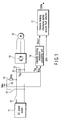
- FIG. 1 is a block diagram of an electric rolling stock control apparatus according to a first embodiment of the present invention. Note that portions which are the same as those in the first embodiment are denoted by the same reference numerals, detailed descriptions thereof will be omitted, and different portions will be mainly described. In the following embodiments as well, overlapping descriptions will be omitted in the same way.
- a direct-current power supply 11 rectifies electric power generated from a direct-current overhead line (catenary) or an engine generator on a rolling stock by a rectifier, and outputs direct-current power.
- the direct-current power supply 11 is connected to a direct-current terminal of an inverter 14 via a first switch 12.
- a filter capacitor 13 is connected between the direct-current terminals of the inverter 14 at a side closer to the inverter 14 than the first switch 12.
- An alternating-current motor 15 serving as a load is connected to the output side of the inverter 14.
- an induction motor is used as the alternating-current motor 15. Further, operation control at variable voltages/variable frequencies (VVVF) is carried out onto the inverter 14.
- a dynamic braking resistor 17 is connected to the direct-current terminal of the inverter 4 via a second switch 16.
- the electric rolling stock control apparatus controls the alternating-current motor 15 as a generator by opening the first switch 12 and closing the second switch 16. The generated power is consumed by the dynamic braking resistor 17.
- An electric current detector 18 detects a value of current IBRe flowing in the dynamic braking resistor 17.
- the value of current IBRe detected by the electric current detector 18 is inputted to a dynamic braking resistance calculating unit 19.
- a voltage detector 20 detects a voltage Vdc of the filter capacitor 13 (voltage between the direct-current terminals of the inverter 14, or voltage between the both terminals of the dynamic braking resistor 17).
- the value of voltage Vdc detected by the voltage detector 20 is inputted to the dynamic braking resistance calculating unit 19.
- the dynamic braking resistance calculating unit 19 calculates a value of resistance BReS1 on the basis of the value of current IBRe and the value of voltage Vdc as in formula (1).
- BReS ⁇ 1 Vdc / IBRe
- a dynamic braking resistance partial ground fault detector 21 determines whether or not the dynamic braking resistor 17 is in a sound state or in a partial ground fault state on the basis of the value of resistance BReS1 which is an output from the dynamic braking resistance calculating unit 19 and a rated value (predetermined value) BRe of the dynamic braking resistor 17.
- the dynamic braking resistance partial ground fault detector 21 stops the brake operation or displays the defect when the value of resistance BReS1 calculated by the dynamic braking resistance calculating unit 19 is less than the predetermined value BRe, i.e., when the dynamic braking resistance partial ground fault detection signal GBRe is 1.
- the dynamic braking resistance calculating unit 19 calculates a value of resistance BReS1 of the dynamic braking resistor 17 on the basis of a value of current IBRe detected by the electric current detector 18 and a value of voltage Vdc detected by the voltage detector 20.
- the dynamic braking resistance partial ground fault detector 21 stops the brake operation or displays the defect when the value of resistance BReS1 calculated by the dynamic braking resistance calculating unit 19 is less than the predetermined value BRe.
- the electric rolling stock control apparatus can continue to drive the electric rolling stock. Accordingly, it is possible to improve the reliability of the system.
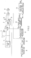
- FIG. 2 is a block diagram showing an electric rolling stock control apparatus according to a second embodiment of the present invention.
- a dynamic braking resistance calculating unit 19A in place of the dynamic braking resistance calculating unit 19 and the dynamic braking resistance partial ground fault detector 21 in the first embodiment shown in FIG. 1, a dynamic braking resistance calculating unit 19A, a dynamic braking resistance partial ground fault detector 21A, a coordinate converting unit 24, a torque computing unit 25, and an electric power computing unit 26 are provided.
- an electric current detector 22, an electric current detector 23, and a velocity sensor 27 are provided.
- the dynamic braking resistance calculating unit 19A calculates a value of resistance BReS2 of the dynamic braking resistor 17 on the basis of braking electric power PB and a value of voltage Vdc of the dynamic braking resistor 17.
- the electric current detector 22 detects a value of u-phase current Iu of the alternating-current motor 15.
- the electric current detector 23 detects a value of w-phase current Iw of the alternating-current motor 15.
- the value of u-phase current Iu detected by the electric current detector 22 and the value of w-phase current Iw detected by the electric current detector 23 are inputted to the coordinate converting unit 24.
- the coordinate converting unit 24 calculates a value of torque current Iq and a value of exciting current Id by dq axis transformation computing on the basis of the value of u-phase current Iu and the value of w-phase current Iw, and outputs those to the torque computing unit 25.
- the dq axis coordinates are a coordinate system divided in accordance with a component acting on torque and a component which does not act on torque.
- K1 is a coefficient which is substantially the same as mutual inductance.
- the torque Tr of the alternating-current motor 15 computed by the torque computing unit 25 is inputted to the electric power computing unit 26.
- the velocity sensor 27 detects a motor velocity ⁇ s which is a rotational velocity of the alternating-current motor 15.
- the motor velocity ⁇ s detected by the velocity sensor is inputted to the electric power computing unit 26.
- the electric power computing unit 26 computes braking electric power PB by formula (3) on the basis of the torque Tr and the motor velocity ⁇ s.
- PB Tr ⁇ ⁇ s
- the braking electric power PB computed by the electric power computing unit 26 is inputted to the dynamic braking resistance calculating unit 19A.
- the value of voltage Vdc of the filter capacitor 13 detected by the voltage detector 20 is inputted to the dynamic braking resistance calculating unit 19A.
- the dynamic braking resistance calculating unit 19A calculates a value of resistance BReS2 by formula (4) on the basis of the braking electric power PB and the value of voltage Vdc.
- BReS ⁇ 2 Vdc ⁇ 2 / PB
- the dynamic braking resistance partial ground fault detector 21A determines whether the dynamic braking resistor 17 is in a sound state or in a partial ground fault state on the basis of the value of resistance BReS2 which is an output from the dynamic braking resistance calculating unit 19A and the rated value BRe of the dynamic braking resistor 17.
- the dynamic braking resistance partial ground fault detector 21A stops the brake operation or displays the defect when the value of resistance BReS2 calculated by the dynamic braking resistance calculating unit 19A is less than the predetermined value BRe, i.e., when the dynamic braking resistance partial ground fault detection signal GBRe is 1.
- the same effects as those in the first embodiment can be obtained by calculating the value of resistance BReS2 of the dynamic braking resistor 17 on the basis of the braking electric power PB and the value of voltage Vdc of the dynamic braking resistor 17.
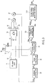
- FIG. 3 is a block diagram of an electric rolling stock control apparatus according to a third embodiment of the present invention.
- a dynamic braking resistance calculating unit 19A and the dynamic braking resistance partial ground fault detector 21A in the second embodiment shown in FIG. 2 a dynamic braking resistance calculating unit 19B and a dynamic braking resistance partial ground fault detector 21B are provided. Further, an electric current detector 18 is provided in place of the voltage detector 20.
- the dynamic braking resistance calculating unit 19B calculates a value of resistance BReS3 of the dynamic braking resistor 17 on the basis of braking electric power PB and a value of current IBRe.
- the value of current IBRe detected by the electric current detector 18 is inputted to the dynamic braking resistance calculating unit 19B.
- the braking electric power PB computed by an electric power computing unit 26 is inputted to the dynamic braking resistance calculating unit 19B.
- the dynamic braking resistance calculating unit 19B computes a value of resistance BReS3 by formula (5) using the braking electric power PB and the value of current IBRe being inputted.
- BReS ⁇ 3 PB / IBRe ⁇ 2
- the dynamic braking resistance partial ground fault detector 21B determines whether the dynamic braking resistor 17 is in a sound state or in a partial ground fault state on the basis of a value of resistance BReS3 which is an output from the dynamic braking resistance calculating unit 19B and a rated value BRe of the dynamic braking resistor 17.
- the dynamic braking resistance partial ground fault detector 21B stops the brake operation or displays the defect when the value of resistance BReS3 calculated by the dynamic braking resistance calculating unit 19B is less than the predetermined value BRe, i.e., when the dynamic braking resistance partial ground fault detection signal GBRe is 1.
- the same effects as those in the second embodiment can be obtained by calculating the value of resistance BReS3 of the dynamic braking resistor 17 on the basis of the braking electric power PB and the value of current IBRe flowing in the dynamic braking resistor 17.
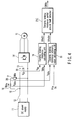
- FIG. 4 is a block diagram of an electric rolling stock control apparatus according to a fourth embodiment of the present invention.
- a dynamic braking resistance partial ground fault detector 21C in place of the dynamic braking resistance partial ground fault detector 21 in the first embodiment shown in FIG. 1, a dynamic braking resistance partial ground fault detector 21C, a temperature detector 28, and a dynamic braking resistance reference value calculating unit 29 are provided.
- the temperature detector 28 detects a temperature TBRe of the dynamic braking resistor 17.
- the temperature TBRe detected by the temperature detector 28 is inputted to the dynamic braking resistance reference value calculating unit 29.
- the dynamic braking resistance reference value calculating unit 29 calculates a calculation reference value (predetermined value) BReS4 by formula (6) on the basis of the temperature TBRe.
- BReS ⁇ 4 RTK + K ⁇ 2 ⁇ Vdc / TBRe - TK
- RTK is a value of resistance when a resistive element is at a temperature TK
- K2 is a temperature coefficient
- the dynamic braking resistance partial ground fault detector 21C determines whether the dynamic braking resistor 17 is in a sound state or in a partial ground fault state on the basis of the value of resistance BReS1 which is an output from the dynamic braking resistance calculating unit 19 and the calculation reference value BReS4 which is an output from the dynamic braking resistance reference value calculating unit 29.
- the dynamic braking resistance partial ground fault detector 21C stops the brake operation or displays the defect when the value of resistance BReS1 calculated by the dynamic braking resistance calculating unit 19 is less than the calculation reference value BReS4 calculated by the dynamic braking resistance reference value calculating unit 29, i.e., when the dynamic braking resistance partial ground fault detection signal GBRe is 1.
- the value of resistance BReS1 calculated by the dynamic braking resistance calculating unit 19 is compared with the calculation reference value BReS4 calculated on the basis of the temperature TBRe of the dynamic braking resistor 17.
- the same effects as those in the first embodiment can be obtained.
- a reference value of the dynamic braking resistor is adjusted in accordance with a change in temperature, it is possible to further improve a detection accuracy compared with that of the first embodiment. Namely, it is possible to detect an ground fault at a portion closer to a terminal at the grounded side of the dynamic braking resistor 17, which makes it possible to further improve the reliability of the system.
- FIG. 5 is a block diagram showing an electric rolling stock control apparatus according to a fifth embodiment of the present invention.
- a dynamic braking resistance calculating unit 19A in place of the dynamic braking resistance calculating unit 19 and the dynamic braking resistance partial ground fault detector 21C in the fourth embodiment shown in FIG. 4, a dynamic braking resistance calculating unit 19A, a dynamic braking resistance partial ground fault detector 21D, a coordinate converting unit 24, a torque computing unit 25, and an electric power computing unit 26 are provided. Further, in place of the electric current detector 18, an electric current detector 22, an electric current detector 23, and an velocity sensor 27 are provided. Note that a method for calculating a value of resistance BReS2 by the dynamic braking resistance calculating unit 19A is as described in the second embodiment.
- the dynamic braking resistance partial ground fault detector 21D determines whether the dynamic braking resistor 17 is in a sound state or in a partial ground fault state on the basis of the value of resistance BReS2 which is an output from the dynamic braking resistance calculating unit 19A and the calculation reference value (predetermined value) BReS4 which is an output from a dynamic braking resistance reference value calculating unit 29.
- the same effects as those in the fourth embodiment can be obtained by calculating the value of resistance BReS2 of the dynamic braking resistor 17 on the basis of the braking electric power PB and the value of voltage Vdc of the dynamic braking resistor 17.
- FIG. 6 is a block diagram of an electric rolling stock control apparatus according to a sixth embodiment of the present invention.
- a dynamic braking resistance calculating unit 19B and a dynamic braking resistance partial ground fault detector 21E are provided in place of the voltage detector 20.
- an electric current detector 18 is provided in place of the voltage detector 20. Note that a method for calculating a value of resistance BReS3 by the dynamic braking resistance calculating unit 19B is as described in the third embodiment.
- the dynamic braking resistance partial ground fault detector 21E determines whether the dynamic braking resistor 17 is in a sound state or in a partial ground fault state on the basis of the value of resistance BReS3 which is an output from the dynamic braking resistance calculating unit 19B and the calculation reference value (predetermined value) BReS4 which is an output from a dynamic braking resistance reference value calculating unit 29.
- the same effects as those in the fourth embodiment can be obtained by calculating the value of resistance BReS3 of the dynamic braking resistor 17 on the basis of the braking electric power PB and the value of current IBRe of the dynamic braking resistor 17.
- the inverter 14 has been described as an inverter controlled at VVVF. However, the inverter 14 may be an inverter controlled at constant voltage/constant frequency (CVCF), or may be an inverter controlled in another system.
- CVCF constant voltage/constant frequency
Abstract
An electric rolling stock control apparatus includes, an alternating-current motor (15) for making an electric rolling stock run, and for carrying out brake control of the electric rolling stock, a dynamic braking resistor (17) for consuming electric power generated by the brake control, electric current detector (18) for detecting a value of current flowing in the dynamic braking resistor (17), voltage detector (20) for detecting a value of voltage between both terminals of the dynamic braking resistor (17), dynamic braking resistance calculating unit (19) for calculating a value of resistance of the dynamic braking resistor (17) on the basis of the value of current and the value of voltage, and a dynamic braking resistance partial ground fault detector (21) for detecting a partial ground fault in the dynamic braking resistor (17) when the value of resistance is less than a predetermined value.
Description
- The present invention relates to an electric rolling stock control apparatus having a mechanism of carrying out brake control of an electric rolling stock by making an alternating-current motor carry out generation control.
- Generally, an electric rolling stock control apparatus carries out brake control of an electric rolling stock by carrying out generation control of an alternating-current motor. Concretely, the alternating-current motor onto which generation control has been carried out converts rotational energy into alternating-current power. An inverter converts the alternating-current power converted by the alternating-current motor into direct-current power. The direct-current power converted by the inverter is consumed as Joule heat by a dynamic braking resistor.
- In such an electric rolling stock control apparatus, when Joule heat consumed in a dynamic braking resistor is made to be excessive, the dynamic braking resistor reaches a high temperature. In accordance therewith, there are cases in which the dynamic braking resistor is burned out or emits smoke.
- Then, there is disclosed an electric rolling stock control apparatus which detects an excess temperature of a dynamic braking resistor, and in which it is possible to detect an excess temperature of the dynamic braking resistor without providing a temperature detector (for example, refer to Jpn. Pat. Appln. KOKAI Publication No. 2005-27454). Namely, the electric rolling stock control apparatus calculates a value of resistance of the dynamic braking resistor on the basis of a value of current flowing in the dynamic braking resistor, and values of voltages at the both ends of the dynamic braking resistor. The electric rolling stock control apparatus compares the calculated value of resistance with a value of resistance at an allowable temperature of the dynamic braking resistor computed in advance. The electric rolling stock control apparatus detects that the dynamic braking resistor is at an excess temperature when the value of resistance is greater as a result of the comparison.
- However, when a partial short-circuit is brought about in the dynamic braking resistor, consumption of the same electric power as that in a normal operation by the dynamic braking resistor makes the current-carrying part overloaded. In this case burnout and the like may be brought about in the dynamic braking resistor. In an electric rolling stock control apparatus as described above, it is impossible to detect a partial ground fault in the dynamic braking resistor.
- An object of the invention is to provide an electric rolling stock control apparatus capable of detecting a partial ground fault in a dynamic braking resistor for consuming electric power generated by brake control of an electric rolling stock.
- In accordance with one embodiment of the present invention, an electric rolling stock control apparatus includes, an inverter for converting converts direct-current power from a direct-current power supply into three-phase alternating-current power; an alternating-current motor for making an electric rolling stock run when driven by the three-phase alternating-current power converted by the inverter, and for carrying out brake control of the electric rolling stock when controlled as a generator; a dynamic braking resistor for consuming electric power generated by the alternating-current motor by the brake control of the electric rolling stock; electric current detecting means for detecting a value of current flowing in the dynamic braking resistor; voltage detecting means for detecting a value of voltage between both terminals of the dynamic braking resistor; dynamic braking resistance calculating means for calculating a value of resistance of the dynamic braking resistor on the basis of the value of current detected by the electric current detecting means and the value of voltage detected by the voltage detecting means; and a dynamic braking resistance partial ground fault detector for detecting a partial ground fault in the dynamic braking resistor when the value of resistance calculated by the dynamic braking resistance calculating means is less than a predetermined value.
- The invention can be more fully understood from the following detailed description when taken in conjunction with the accompanying drawings, in which:
- FIG. 1 is a block diagram of an electric rolling stock control apparatus according to a first embodiment of the present invention;
- FIG. 2 is a block diagram of an electric rolling stock control apparatus according to a second embodiment of the present invention;
- FIG. 3 is a block diagram of an electric rolling stock control apparatus according to a third embodiment of the present invention;
- FIG. 4 is a block diagram of an electric rolling stock control apparatus according to a fourth embodiment of the present invention;
- FIG. 5 is a block diagram of an electric rolling stock control apparatus according to a fifth embodiment of the present invention; and
- FIG. 6 is a block diagram of an electric rolling stock control apparatus according to a sixth embodiment of the present invention.
- Hereinafter, embodiments of the present invention will be described with reference to the drawings.
- FIG. 1 is a block diagram of an electric rolling stock control apparatus according to a first embodiment of the present invention. Note that portions which are the same as those in the first embodiment are denoted by the same reference numerals, detailed descriptions thereof will be omitted, and different portions will be mainly described. In the following embodiments as well, overlapping descriptions will be omitted in the same way.
- A direct-
current power supply 11 rectifies electric power generated from a direct-current overhead line (catenary) or an engine generator on a rolling stock by a rectifier, and outputs direct-current power. The direct-current power supply 11 is connected to a direct-current terminal of aninverter 14 via afirst switch 12. Afilter capacitor 13 is connected between the direct-current terminals of theinverter 14 at a side closer to theinverter 14 than thefirst switch 12. An alternating-current motor 15 serving as a load is connected to the output side of theinverter 14. Usually, an induction motor is used as the alternating-current motor 15. Further, operation control at variable voltages/variable frequencies (VVVF) is carried out onto theinverter 14. - Further, a
dynamic braking resistor 17 is connected to the direct-current terminal of theinverter 4 via asecond switch 16. At the time of carrying out a brake operation of the electric rolling stock, the electric rolling stock control apparatus controls the alternating-current motor 15 as a generator by opening thefirst switch 12 and closing thesecond switch 16. The generated power is consumed by thedynamic braking resistor 17. - An
electric current detector 18 detects a value of current IBRe flowing in thedynamic braking resistor 17. The value of current IBRe detected by the electriccurrent detector 18 is inputted to a dynamic brakingresistance calculating unit 19. Avoltage detector 20 detects a voltage Vdc of the filter capacitor 13 (voltage between the direct-current terminals of theinverter 14, or voltage between the both terminals of the dynamic braking resistor 17). The value of voltage Vdc detected by thevoltage detector 20 is inputted to the dynamic brakingresistance calculating unit 19. The dynamic brakingresistance calculating unit 19 calculates a value of resistance BReS1 on the basis of the value of current IBRe and the value of voltage Vdc as in formula (1).
- A dynamic braking resistance partial
ground fault detector 21 determines whether or not thedynamic braking resistor 17 is in a sound state or in a partial ground fault state on the basis of the value of resistance BReS1 which is an output from the dynamic brakingresistance calculating unit 19 and a rated value (predetermined value) BRe of thedynamic braking resistor 17. - For example, the dynamic braking resistance partial
ground fault detector 21 outputs a dynamic braking resistance partial ground fault detection signal GBRe (GBRe = 1) when the value of resistance BReS1 is less than the rated value (predetermined value) BRe of the dynamic braking resistor 17 (in the case of BReS1 < BRe). The dynamic braking resistance partialground fault detector 21 outputs a dynamic braking resistance partial ground fault detection signal GBRe (GBRe = 0) when the value of resistance BReS1 is greater than or equal to the rated value (predetermined value) BRe of the dynamic braking resistor 17 (in the case of BReS1 ≥ BRe). Here, the dynamic braking resistance partial ground fault detection signal GBRe = 1 shows a partial ground fault state. The dynamic braking resistance partial ground fault detection signal GBRe = 0 shows a sound state. - The dynamic braking resistance partial
ground fault detector 21 stops the brake operation or displays the defect when the value of resistance BReS1 calculated by the dynamic brakingresistance calculating unit 19 is less than the predetermined value BRe, i.e., when the dynamic braking resistance partial ground fault detection signal GBRe is 1. - In accordance with the first embodiment, the dynamic braking
resistance calculating unit 19 calculates a value of resistance BReS1 of thedynamic braking resistor 17 on the basis of a value of current IBRe detected by theelectric current detector 18 and a value of voltage Vdc detected by thevoltage detector 20. The dynamic braking resistance partialground fault detector 21 stops the brake operation or displays the defect when the value of resistance BReS1 calculated by the dynamic brakingresistance calculating unit 19 is less than the predetermined value BRe. In accordance therewith, it is possible to prevent the dynamic braking resistor from being burned out or the like even in a state in which a defect such as a short circuit or the like is brought about in thedynamic braking resistor 17. Further, the electric rolling stock control apparatus can continue to drive the electric rolling stock. Accordingly, it is possible to improve the reliability of the system. - FIG. 2 is a block diagram showing an electric rolling stock control apparatus according to a second embodiment of the present invention. In the second embodiment, in place of the dynamic braking
resistance calculating unit 19 and the dynamic braking resistance partialground fault detector 21 in the first embodiment shown in FIG. 1, a dynamic brakingresistance calculating unit 19A, a dynamic braking resistance partialground fault detector 21A, acoordinate converting unit 24, atorque computing unit 25, and an electricpower computing unit 26 are provided. Further, in place of theelectric current detector 18, an electriccurrent detector 22, anelectric current detector 23, and avelocity sensor 27 are provided. - The dynamic braking
resistance calculating unit 19A calculates a value of resistance BReS2 of thedynamic braking resistor 17 on the basis of braking electric power PB and a value of voltage Vdc of thedynamic braking resistor 17. - The
electric current detector 22 detects a value of u-phase current Iu of the alternating-current motor 15. Theelectric current detector 23 detects a value of w-phase current Iw of the alternating-current motor 15. The value of u-phase current Iu detected by theelectric current detector 22 and the value of w-phase current Iw detected by theelectric current detector 23 are inputted to thecoordinate converting unit 24. The coordinate convertingunit 24 calculates a value of torque current Iq and a value of exciting current Id by dq axis transformation computing on the basis of the value of u-phase current Iu and the value of w-phase current Iw, and outputs those to thetorque computing unit 25. The dq axis coordinates are a coordinate system divided in accordance with a component acting on torque and a component which does not act on torque. - The
torque computing unit 25 computes torque Tr by formula (2) using a value of torque current Iq and a value of exciting current Id which are outputs from the coordinate convertingunit 24 being inputted.
- However, K1 is a coefficient which is substantially the same as mutual inductance.
- The torque Tr of the alternating-
current motor 15 computed by thetorque computing unit 25 is inputted to the electricpower computing unit 26. Thevelocity sensor 27 detects a motor velocity ωs which is a rotational velocity of the alternating-current motor 15. The motor velocity ωs detected by the velocity sensor is inputted to the electricpower computing unit 26. The electricpower computing unit 26 computes braking electric power PB by formula (3) on the basis of the torque Tr and the motor velocity ωs.
- The braking electric power PB computed by the electric
power computing unit 26 is inputted to the dynamic brakingresistance calculating unit 19A. The value of voltage Vdc of thefilter capacitor 13 detected by thevoltage detector 20 is inputted to the dynamic brakingresistance calculating unit 19A. The dynamic brakingresistance calculating unit 19A calculates a value of resistance BReS2 by formula (4) on the basis of the braking electric power PB and the value of voltage Vdc.
- The dynamic braking resistance partial
ground fault detector 21A determines whether thedynamic braking resistor 17 is in a sound state or in a partial ground fault state on the basis of the value of resistance BReS2 which is an output from the dynamic brakingresistance calculating unit 19A and the rated value BRe of thedynamic braking resistor 17. - For example, the dynamic braking resistance partial
ground fault detector 21A outputs a dynamic braking resistance partial ground fault detection signal GBRe (GBRe = 1) when the value of resistance BReS2 is less than the rated value (predetermined value) BRe of the dynamic braking resistor 17 (in the case of BReS2 < BRe). The dynamic braking resistance partialground fault detector 21A outputs a dynamic braking resistance partial ground fault detection signal GBRe (GBRe = 0) when the value of resistance BReS2 is greater than or equal to the rated value (predetermined value) BRe of the dynamic braking resistor 17 (in the case of BReS2 ≥ BRe). Here, the dynamic braking resistance partial ground fault detection signal GBRe = 1 indicates a partial ground fault state. The dynamic braking resistance partial ground fault detection signal GBRe = 0 indicates a sound state. - The dynamic braking resistance partial
ground fault detector 21A stops the brake operation or displays the defect when the value of resistance BReS2 calculated by the dynamic brakingresistance calculating unit 19A is less than the predetermined value BRe, i.e., when the dynamic braking resistance partial ground fault detection signal GBRe is 1. - In accordance with the second embodiment, the same effects as those in the first embodiment can be obtained by calculating the value of resistance BReS2 of the
dynamic braking resistor 17 on the basis of the braking electric power PB and the value of voltage Vdc of thedynamic braking resistor 17. - FIG. 3 is a block diagram of an electric rolling stock control apparatus according to a third embodiment of the present invention. In the third embodiment, in place of the dynamic braking
resistance calculating unit 19A and the dynamic braking resistance partialground fault detector 21A in the second embodiment shown in FIG. 2, a dynamic brakingresistance calculating unit 19B and a dynamic braking resistance partialground fault detector 21B are provided. Further, an electriccurrent detector 18 is provided in place of thevoltage detector 20. - The dynamic braking
resistance calculating unit 19B calculates a value of resistance BReS3 of thedynamic braking resistor 17 on the basis of braking electric power PB and a value of current IBRe. - The value of current IBRe detected by the electric
current detector 18 is inputted to the dynamic brakingresistance calculating unit 19B. The braking electric power PB computed by an electricpower computing unit 26 is inputted to the dynamic brakingresistance calculating unit 19B. The dynamic brakingresistance calculating unit 19B computes a value of resistance BReS3 by formula (5) using the braking electric power PB and the value of current IBRe being inputted.
- The dynamic braking resistance partial
ground fault detector 21B determines whether thedynamic braking resistor 17 is in a sound state or in a partial ground fault state on the basis of a value of resistance BReS3 which is an output from the dynamic brakingresistance calculating unit 19B and a rated value BRe of thedynamic braking resistor 17. - For example, the dynamic braking resistance partial
ground fault detector 21B outputs a dynamic braking resistance partial ground fault detection signal GBRe (GBRe = 1) when the value of resistance BReS3 is less than the rated value (predetermined value) BRe of the dynamic braking resistor 17 (in the case of BReS3 < BRe). The dynamic braking resistance partialground fault detector 21B outputs a dynamic braking resistance partial ground fault detection signal GBRe (GBRe = 0) when the value of resistance BReS3 is greater than or equal to the rated value (predetermined value) BRe of the dynamic braking resistor 17 (in the case of BReS3 ≥ BRe). Here, the dynamic braking resistance partial ground fault detection signal GBRe = 1 indicates a partial ground fault state. The dynamic braking resistance partial ground fault detection signal GBRe = 0 indicates a sound state. - The dynamic braking resistance partial
ground fault detector 21B stops the brake operation or displays the defect when the value of resistance BReS3 calculated by the dynamic brakingresistance calculating unit 19B is less than the predetermined value BRe, i.e., when the dynamic braking resistance partial ground fault detection signal GBRe is 1. - In accordance with the third embodiment, the same effects as those in the second embodiment can be obtained by calculating the value of resistance BReS3 of the
dynamic braking resistor 17 on the basis of the braking electric power PB and the value of current IBRe flowing in thedynamic braking resistor 17. - FIG. 4 is a block diagram of an electric rolling stock control apparatus according to a fourth embodiment of the present invention. In the fourth embodiment, in place of the dynamic braking resistance partial
ground fault detector 21 in the first embodiment shown in FIG. 1, a dynamic braking resistance partialground fault detector 21C, atemperature detector 28, and a dynamic braking resistance referencevalue calculating unit 29 are provided. - The
temperature detector 28 detects a temperature TBRe of thedynamic braking resistor 17. The temperature TBRe detected by thetemperature detector 28 is inputted to the dynamic braking resistance referencevalue calculating unit 29. The dynamic braking resistance referencevalue calculating unit 29 calculates a calculation reference value (predetermined value) BReS4 by formula (6) on the basis of the temperature TBRe.
- Here, RTK is a value of resistance when a resistive element is at a temperature TK, and K2 is a temperature coefficient.
- The dynamic braking resistance partial
ground fault detector 21C determines whether thedynamic braking resistor 17 is in a sound state or in a partial ground fault state on the basis of the value of resistance BReS1 which is an output from the dynamic brakingresistance calculating unit 19 and the calculation reference value BReS4 which is an output from the dynamic braking resistance referencevalue calculating unit 29. - For example, the dynamic braking resistance partial
ground fault detector 21C outputs a dynamic braking resistance partial ground fault detection signal GBRe (GBRe = 1) when the value of resistance BReS1 is less than the calculation reference value BReS4 (BReS1 < BReS4). The dynamic braking resistance partialground fault detector 21C outputs a dynamic braking resistance partial ground fault detection signal GBRe (GBRe = 0) when the value of resistance BReS1 is greater than or equal to the calculation reference value BReS4 (BReS1 ≥ BReS4). Here, the dynamic braking resistance partial ground fault detection signal GBRe = 1 indicates a partial ground fault state. The dynamic braking resistance partial ground fault detection signal GBRe = 0 indicates a sound state. - The dynamic braking resistance partial
ground fault detector 21C stops the brake operation or displays the defect when the value of resistance BReS1 calculated by the dynamic brakingresistance calculating unit 19 is less than the calculation reference value BReS4 calculated by the dynamic braking resistance referencevalue calculating unit 29, i.e., when the dynamic braking resistance partial ground fault detection signal GBRe is 1. - In accordance with the fourth embodiment, the value of resistance BReS1 calculated by the dynamic braking
resistance calculating unit 19 is compared with the calculation reference value BReS4 calculated on the basis of the temperature TBRe of thedynamic braking resistor 17. In accordance therewith, the same effects as those in the first embodiment can be obtained. Moreover, because a reference value of the dynamic braking resistor is adjusted in accordance with a change in temperature, it is possible to further improve a detection accuracy compared with that of the first embodiment. Namely, it is possible to detect an ground fault at a portion closer to a terminal at the grounded side of thedynamic braking resistor 17, which makes it possible to further improve the reliability of the system. - FIG. 5 is a block diagram showing an electric rolling stock control apparatus according to a fifth embodiment of the present invention. In the fifth embodiment, in place of the dynamic braking
resistance calculating unit 19 and the dynamic braking resistance partialground fault detector 21C in the fourth embodiment shown in FIG. 4, a dynamic brakingresistance calculating unit 19A, a dynamic braking resistance partialground fault detector 21D, a coordinate convertingunit 24, atorque computing unit 25, and an electricpower computing unit 26 are provided. Further, in place of the electriccurrent detector 18, an electriccurrent detector 22, an electriccurrent detector 23, and anvelocity sensor 27 are provided. Note that a method for calculating a value of resistance BReS2 by the dynamic brakingresistance calculating unit 19A is as described in the second embodiment. - The dynamic braking resistance partial
ground fault detector 21D determines whether thedynamic braking resistor 17 is in a sound state or in a partial ground fault state on the basis of the value of resistance BReS2 which is an output from the dynamic brakingresistance calculating unit 19A and the calculation reference value (predetermined value) BReS4 which is an output from a dynamic braking resistance referencevalue calculating unit 29. - For example, the dynamic braking resistance partial
ground fault detector 21D outputs a dynamic braking resistance partial ground fault detection signal GBRe (GBRe = 1) when the value of resistance BReS2 is less than the calculation reference value BReS4 (BReS2 < BReS4). The dynamic braking resistance partialground fault detector 21D outputs a dynamic braking resistance partial ground fault detection signal GBRe (GBRe = 0) when the value of resistance BReS2 is greater than or equal to the calculation reference value BReS4 (BReS2 ≥ BReS4). Here, the dynamic braking resistance partial ground fault detection signal GBRe = 1 indicates a partial ground fault state. The dynamic braking resistance partial ground fault detection signal GBRe = 0 indicates a sound state. - In accordance with the fifth embodiment, the same effects as those in the fourth embodiment can be obtained by calculating the value of resistance BReS2 of the
dynamic braking resistor 17 on the basis of the braking electric power PB and the value of voltage Vdc of thedynamic braking resistor 17. - FIG. 6 is a block diagram of an electric rolling stock control apparatus according to a sixth embodiment of the present invention. In the sixth embodiment, in place of the dynamic braking
resistance calculating unit 19A and the dynamic braking resistance partialground fault detector 21D in the fifth embodiment shown in FIG. 5, a dynamic brakingresistance calculating unit 19B and a dynamic braking resistance partialground fault detector 21E are provided. Further, an electriccurrent detector 18 is provided in place of thevoltage detector 20. Note that a method for calculating a value of resistance BReS3 by the dynamic brakingresistance calculating unit 19B is as described in the third embodiment. - The dynamic braking resistance partial
ground fault detector 21E determines whether thedynamic braking resistor 17 is in a sound state or in a partial ground fault state on the basis of the value of resistance BReS3 which is an output from the dynamic brakingresistance calculating unit 19B and the calculation reference value (predetermined value) BReS4 which is an output from a dynamic braking resistance referencevalue calculating unit 29. - For example, the dynamic braking resistance partial
ground fault detector 21E outputs a dynamic braking resistance partial ground fault detection signal GBRe (GBRe = 1) when the value of resistance BReS3 is less than the calculation reference value BReS4 (BReS3 < BReS4). The dynamic braking resistance partialground fault detector 21E outputs a dynamic braking resistance partial ground fault detection signal GBRe (GBRe = 0) when the value of resistance BReS3 is greater than or equal to the calculation reference value BReS4 (BReS3 ≥ BReS4). Here, the dynamic braking resistance partial ground fault detection signal GBRe = 1 indicates a partial ground fault state. The dynamic braking resistance partial ground fault detection signal GBRe = 0 indicates a sound state. - In accordance with the sixth embodiment, the same effects as those in the fourth embodiment can be obtained by calculating the value of resistance BReS3 of the
dynamic braking resistor 17 on the basis of the braking electric power PB and the value of current IBRe of thedynamic braking resistor 17. - Note that the
inverter 14 has been described as an inverter controlled at VVVF. However, theinverter 14 may be an inverter controlled at constant voltage/constant frequency (CVCF), or may be an inverter controlled in another system.
Claims (6)
- An electric rolling stock control apparatus characterized by comprising:an inverter (14) for converting converts direct-current power from a direct-current power supply (11) into three-phase alternating-current power;an alternating-current motor (15) for making an electric rolling stock run when driven by the three-phase alternating-current power converted by the inverter (14), and for carrying out brake control of the electric rolling stock when controlled as a generator;a dynamic braking resistor (17) for consuming electric power generated by the alternating-current motor (15) by the brake control of the electric rolling stock;electric current detecting means (18) for detecting a value of current flowing in the dynamic braking resistor (17);voltage detecting means (20) for detecting a value of voltage between both terminals of the dynamic braking resistor (17);dynamic braking resistance calculating means (19) for calculating a value of resistance of the dynamic braking resistor (17) on the basis of the value of current detected by the electric current detecting means (18) and the value of voltage detected by the voltage detecting means (20); anda dynamic braking resistance partial ground fault detector (21) for detecting a partial ground fault in the dynamic braking resistor (17) when the value of resistance calculated by the dynamic braking resistance calculating means (19) is less than a predetermined value.
- The electric rolling stock control apparatus according to claim 1, characterized by further comprising:temperature detecting means (28) for detecting a temperature of the dynamic braking resistor; anddynamic braking resistance reference value calculating means (29) for calculating the predetermined value used to detect a partial ground fault by the dynamic braking resistance partial ground fault detector (21) on the basis of the temperature detected by the temperature detecting means (28).
- An electric rolling stock control apparatus characterized by comprising:an inverter (14) for converting direct-current power from a direct-current power supply (11) into three-phase alternating-current power;an alternating-current motor (15) for making an electric rolling stock run when driven by the three-phase alternating-current power converted by the inverter (14), and for carrying out brake control of the electric rolling stock when controlled as a generator;a dynamic braking resistor (17) for consuming electric power generated by the alternating-current motor (15) by the brake control of the electric rolling stock;voltage detecting means (20) for detecting a value of voltage between both terminals of the dynamic braking resistor (17);first-phase current detecting means (22) for detecting a value of current flowing in a first phase of the three-phase alternating-current power converted by the inverter (14);second-phase current detecting means (23) for detecting a value of current flowing in a second phase of the three-phase alternating-current power converted by the inverter (14);velocity detecting means (27) for detecting a rotational velocity of the alternating-current motor;coordinate converting means (24) for converting the value of current detected by the first-phase current detecting means (22) and the value of current detected by the second-phase current detecting means (23) into a value of current of a dq axis coordinate system;torque computing means (25) for computing torque of the alternating-current motor (15) on the basis of the value of current converted by the coordinate converting means (24);electric power computing means (26) for computing braking electric power on the basis of the torque computed by the torque computing means (25) and the rotational velocity detected by the velocity detecting means (27);dynamic braking resistance calculating means (19) for calculating a value of resistance of the dynamic braking resistor (17) on the basis of the braking electric power computed by the electric power computing means (26) and the value of voltage detected by the voltage detecting means (20); anda dynamic braking resistance partial ground fault detector (21) for detecting a partial ground fault in the dynamic braking resistor (17) when the value of resistance calculated by the dynamic braking resistance calculating means (19) is less than a predetermined value.
- The electric rolling stock control apparatus according to claim 3, characterized by further comprising:temperature detecting means (28) for detecting a temperature of the dynamic braking resistor; anddynamic braking resistance reference value calculating means (29) for calculating the predetermined value used to detect a partial ground fault by the dynamic braking resistance partial ground fault detector (21) on the basis of the temperature detected by the temperature detecting means (28).
- An electric rolling stock control apparatus characterized by comprising:an inverter (14) for converting direct-current power from a direct-current power supply (11) into three-phase alternating-current power;an alternating-current motor (15) for making an electric rolling stock run when driven by the three-phase alternating-current power converted by the inverter (14), and for carrying out brake control of the electric rolling stock when controlled as a generator;a dynamic braking resistor (17) for consuming electric power generated by the alternating-current motor (15) by the brake control of the electric rolling stock;electric current detecting means (18) for detecting a value of current flowing in the dynamic braking resistor (17);first-phase current detecting means (22) for detecting a value of current flowing in a first phase of the three-phase alternating-current power converted by the inverter (14);second-phase current detecting means (23) for detecting a value of current flowing in a second phase of the three-phase alternating-current power converted by the inverter (14);velocity detecting means (27) for detecting a rotational velocity of the alternating-current motor;coordinate converting means (24) for converting the value of current detected by the first-phase current detecting means (22) and the value of current detected by the second-phase current detecting means (23) into a value of current of a dq axis coordinate system;torque computing means (25) for computing torque of the alternating-current motor (15) on the basis of the value of current converted by the coordinate converting means (24);electric power computing means (26) for computing braking electric power on the basis of the torque computed by the torque computing means (25) and the rotational velocity detected by the velocity detecting means (27);dynamic braking resistance calculating means (19) for calculating a value of resistance of the dynamic braking resistor (17) on the basis of the braking electric power computed by the electric power computing means (26) and the value of current detected by the electric current detecting means (18); anda dynamic braking resistance partial ground fault detector (21) for detecting a partial ground fault in the dynamic braking resistor (17) when the value of resistance calculated by the dynamic braking resistance calculating means (19) is less than a predetermined value.
- The electric rolling stock control apparatus according to claim 5, characterized by further comprising:temperature detecting means (28) for detecting a temperature of the dynamic braking resistor; anddynamic braking resistance reference value calculating means (29) for calculating the predetermined value used to detect a partial ground fault by the dynamic braking resistance partial ground fault detector (21) on the basis of the temperature detected by the temperature detecting means (28).
Applications Claiming Priority (1)
| Application Number | Priority Date | Filing Date | Title |
|---|---|---|---|
| JP2006033627A JP4634942B2 (en) | 2006-02-10 | 2006-02-10 | Electric vehicle control device |
Publications (1)
| Publication Number | Publication Date |
|---|---|
| EP1818207A2 true EP1818207A2 (en) | 2007-08-15 |
Family
ID=38049895
Family Applications (1)
| Application Number | Title | Priority Date | Filing Date |
|---|---|---|---|
| EP07002719A Withdrawn EP1818207A2 (en) | 2006-02-10 | 2007-02-08 | Electric rolling stock control apparatus |
Country Status (4)
| Country | Link |
|---|---|
| EP (1) | EP1818207A2 (en) |
| JP (1) | JP4634942B2 (en) |
| CN (1) | CN101024378A (en) |
| ZA (1) | ZA200701177B (en) |
Cited By (9)
| Publication number | Priority date | Publication date | Assignee | Title |
|---|---|---|---|---|
| WO2013186065A1 (en) * | 2012-06-13 | 2013-12-19 | Schneider Toshiba Inverter Europe Sas | Method for estimating the value of a braking resistor used in a power converter |
| CN104097523A (en) * | 2013-04-11 | 2014-10-15 | 陈奔 | Electrical emergency braking system of pure electric vehicle |
| EP2456063A3 (en) * | 2010-11-23 | 2015-06-10 | Schneider Electric Automation Gmbh | Energy distribution recording in a machine with several drives |
| EP3012641A3 (en) * | 2014-10-22 | 2016-06-08 | General Electric Company | System and method for electrical short detection |
| CN107911048A (en) * | 2018-01-09 | 2018-04-13 | 福建船政交通职业学院 | Noise measuring formula energy consuming brake and application method |
| EP3462191A1 (en) * | 2017-09-29 | 2019-04-03 | ALSTOM Transport Technologies | Earth fault detection circuit, transformation line comprising such a circuit, earth fault detection method |
| CN110341487A (en) * | 2018-04-03 | 2019-10-18 | 湖南中车时代电动汽车股份有限公司 | For controlling the control method and system of new energy vehicle braking resistor |
| EP3799295A1 (en) * | 2019-09-30 | 2021-03-31 | Siemens Aktiengesellschaft | Safety device for a load resistor |
| WO2021151667A1 (en) * | 2020-01-27 | 2021-08-05 | Kuka Deutschland Gmbh | Method for controlling at least one servomotor, associated control device, robot and computer program product |
Families Citing this family (5)
| Publication number | Priority date | Publication date | Assignee | Title |
|---|---|---|---|---|
| JP4902514B2 (en) * | 2007-12-14 | 2012-03-21 | 株式会社日立製作所 | VEHICLE DRIVE DEVICE AND RESISTOR BREAKAGE DETECTION METHOD IN VEHICLE DRIVE DEVICE |
| JP5122329B2 (en) * | 2008-02-29 | 2013-01-16 | 株式会社小松製作所 | Dynamic brake module and servo press |
| CN102280852A (en) * | 2011-08-08 | 2011-12-14 | 深圳市英威腾交通技术有限公司 | Method and device for protecting braking resistor of main circuit of electric train |
| JP7090383B2 (en) * | 2014-10-22 | 2022-06-24 | トランスポーテーション アイピー ホールディングス,エルエルシー | Systems and methods for electrical short circuit detection |
| CN107887885B (en) * | 2017-11-09 | 2019-08-20 | 中车株洲电力机车有限公司 | A kind of guard method of braking resistor, system, device and readable storage medium storing program for executing |
Family Cites Families (2)
| Publication number | Priority date | Publication date | Assignee | Title |
|---|---|---|---|---|
| JPH08196001A (en) * | 1995-01-17 | 1996-07-30 | Toyo Electric Mfg Co Ltd | Electric railcar controller and controlling method therefor |
| JP2005027454A (en) * | 2003-07-04 | 2005-01-27 | Mitsubishi Electric Corp | Control device for vehicle |
-
2006
- 2006-02-10 JP JP2006033627A patent/JP4634942B2/en not_active Expired - Fee Related
-
2007
- 2007-02-08 EP EP07002719A patent/EP1818207A2/en not_active Withdrawn
- 2007-02-09 CN CNA2007100080788A patent/CN101024378A/en active Pending
- 2007-02-09 ZA ZA200701177A patent/ZA200701177B/en unknown
Cited By (14)
| Publication number | Priority date | Publication date | Assignee | Title |
|---|---|---|---|---|
| EP2456063A3 (en) * | 2010-11-23 | 2015-06-10 | Schneider Electric Automation Gmbh | Energy distribution recording in a machine with several drives |
| FR2992118A1 (en) * | 2012-06-13 | 2013-12-20 | Schneider Toshiba Inverter | METHOD FOR ESTIMATING A VALUE OF BRAKING RESISTANCE EMPLOYED IN A POWER CONVERTER |
| WO2013186065A1 (en) * | 2012-06-13 | 2013-12-19 | Schneider Toshiba Inverter Europe Sas | Method for estimating the value of a braking resistor used in a power converter |
| CN104097523A (en) * | 2013-04-11 | 2014-10-15 | 陈奔 | Electrical emergency braking system of pure electric vehicle |
| EP4016095A1 (en) * | 2014-10-22 | 2022-06-22 | Transportation IP Holdings, LLC | System and method for electrical short detection |
| EP3012641A3 (en) * | 2014-10-22 | 2016-06-08 | General Electric Company | System and method for electrical short detection |
| US9810730B2 (en) | 2014-10-22 | 2017-11-07 | General Electric Company | System and method for electrical short detection |
| EP3462191A1 (en) * | 2017-09-29 | 2019-04-03 | ALSTOM Transport Technologies | Earth fault detection circuit, transformation line comprising such a circuit, earth fault detection method |
| FR3071928A1 (en) * | 2017-09-29 | 2019-04-05 | Alstom Transport Technologies | MASS FAULT DETECTION CIRCUIT, TRANSFORMATION CHAIN COMPRISING SUCH CIRCUIT, METHOD FOR DETECTING MASS FAULT. |
| CN107911048A (en) * | 2018-01-09 | 2018-04-13 | 福建船政交通职业学院 | Noise measuring formula energy consuming brake and application method |
| CN110341487A (en) * | 2018-04-03 | 2019-10-18 | 湖南中车时代电动汽车股份有限公司 | For controlling the control method and system of new energy vehicle braking resistor |
| EP3799295A1 (en) * | 2019-09-30 | 2021-03-31 | Siemens Aktiengesellschaft | Safety device for a load resistor |
| WO2021063569A1 (en) * | 2019-09-30 | 2021-04-08 | Siemens Aktiengesellschaft | Protection device for a load resistor |
| WO2021151667A1 (en) * | 2020-01-27 | 2021-08-05 | Kuka Deutschland Gmbh | Method for controlling at least one servomotor, associated control device, robot and computer program product |
Also Published As
| Publication number | Publication date |
|---|---|
| JP2007215339A (en) | 2007-08-23 |
| CN101024378A (en) | 2007-08-29 |
| JP4634942B2 (en) | 2011-02-16 |
| ZA200701177B (en) | 2008-07-30 |
Similar Documents
| Publication | Publication Date | Title |
|---|---|---|
| EP1818207A2 (en) | Electric rolling stock control apparatus | |
| US8355226B2 (en) | Ground fault sensing device | |
| US7759888B2 (en) | AC motor controller | |
| JP5274236B2 (en) | Three-phase inverter power circuit protection device | |
| EP1312932B1 (en) | Method for measuring motor constant of induction motor | |
| JP3218954B2 (en) | Abnormality detection device for AC motor control circuit | |
| JP5266687B2 (en) | Anomaly detection device | |
| US8022658B2 (en) | Motor control system including electrical insulation deterioration detecting system | |
| EP2769462B1 (en) | Method and system for detecting a failed rectifier in an ac/dc converter | |
| US9065376B2 (en) | Method for checking the plausibility of the torque of an electric machine and machine controller for controlling an electric machine and for carrying out the method | |
| KR101622011B1 (en) | Method and apparatus for controlling of 3-phase ac motor | |
| CN104364989A (en) | System and method for high resistance ground fault detection and protection in power distribution systems | |
| JP2014513912A (en) | Inverter and method for controlling an electric machine | |
| US20180294751A1 (en) | Apparatus, system and method of fault diagnosis for permanent magnet motor | |
| KR20160084856A (en) | Electric vehicle and device for controlling power converter | |
| JPH06245301A (en) | Open-phase detection system in controller for electric vehicle | |
| JPH10225158A (en) | Controller for induction machine | |
| EP3407483B1 (en) | Direct current sensor, alternating current sensor, and inverter comprising same | |
| KR20150017503A (en) | Apparatus for compensating offset and sensing failure of current sensor for inverter driving and Method thereof | |
| EP1671143B1 (en) | Method of and apparatus for online testing an intermediate link | |
| EP1403161B1 (en) | Method of detecting and controlling the torque of a three-phase motor and device to carry out the method | |
| KR100894380B1 (en) | Electric car control device | |
| KR102182635B1 (en) | A method for detecting inverter failure and the system therefor | |
| EP4199346A1 (en) | Motor winding fault diagnosis | |
| WO2022054243A1 (en) | Power conversion device, supplementary power source device for vehicle, and stopping method for power conversion device |
Legal Events
| Date | Code | Title | Description |
|---|---|---|---|
| PUAI | Public reference made under article 153(3) epc to a published international application that has entered the european phase |
Free format text: ORIGINAL CODE: 0009012 |
|
| 17P | Request for examination filed |
Effective date: 20070208 |
|
| AK | Designated contracting states |
Kind code of ref document: A2 Designated state(s): AT BE BG CH CY CZ DE DK EE ES FI FR GB GR HU IE IS IT LI LT LU LV MC NL PL PT RO SE SI SK TR |
|
| AX | Request for extension of the european patent |
Extension state: AL BA HR MK YU |
|
| STAA | Information on the status of an ep patent application or granted ep patent |
Free format text: STATUS: THE APPLICATION HAS BEEN WITHDRAWN |
|
| 18W | Application withdrawn |
Effective date: 20160223 |