EP1818204A1 - Fuel cell automobile and release tube installation structure for gas fuel automobile - Google Patents
Fuel cell automobile and release tube installation structure for gas fuel automobile Download PDFInfo
- Publication number
- EP1818204A1 EP1818204A1 EP05811414A EP05811414A EP1818204A1 EP 1818204 A1 EP1818204 A1 EP 1818204A1 EP 05811414 A EP05811414 A EP 05811414A EP 05811414 A EP05811414 A EP 05811414A EP 1818204 A1 EP1818204 A1 EP 1818204A1
- Authority
- EP
- European Patent Office
- Prior art keywords
- fuel cell
- release
- hydrogen
- outlet
- vehicle
- Prior art date
- Legal status (The legal status is an assumption and is not a legal conclusion. Google has not performed a legal analysis and makes no representation as to the accuracy of the status listed.)
- Granted
Links
Images



Classifications
-
- B—PERFORMING OPERATIONS; TRANSPORTING
- B60—VEHICLES IN GENERAL
- B60K—ARRANGEMENT OR MOUNTING OF PROPULSION UNITS OR OF TRANSMISSIONS IN VEHICLES; ARRANGEMENT OR MOUNTING OF PLURAL DIVERSE PRIME-MOVERS IN VEHICLES; AUXILIARY DRIVES FOR VEHICLES; INSTRUMENTATION OR DASHBOARDS FOR VEHICLES; ARRANGEMENTS IN CONNECTION WITH COOLING, AIR INTAKE, GAS EXHAUST OR FUEL SUPPLY OF PROPULSION UNITS IN VEHICLES
- B60K15/00—Arrangement in connection with fuel supply of combustion engines or other fuel consuming energy converters, e.g. fuel cells; Mounting or construction of fuel tanks
- B60K15/03—Fuel tanks
- B60K15/035—Fuel tanks characterised by venting means
- B60K15/03519—Valve arrangements in the vent line
-
- B—PERFORMING OPERATIONS; TRANSPORTING
- B60—VEHICLES IN GENERAL
- B60K—ARRANGEMENT OR MOUNTING OF PROPULSION UNITS OR OF TRANSMISSIONS IN VEHICLES; ARRANGEMENT OR MOUNTING OF PLURAL DIVERSE PRIME-MOVERS IN VEHICLES; AUXILIARY DRIVES FOR VEHICLES; INSTRUMENTATION OR DASHBOARDS FOR VEHICLES; ARRANGEMENTS IN CONNECTION WITH COOLING, AIR INTAKE, GAS EXHAUST OR FUEL SUPPLY OF PROPULSION UNITS IN VEHICLES
- B60K8/00—Arrangement or mounting of propulsion units not provided for in one of main groups B60K1/00 - B60K7/00
-
- B—PERFORMING OPERATIONS; TRANSPORTING
- B60—VEHICLES IN GENERAL
- B60K—ARRANGEMENT OR MOUNTING OF PROPULSION UNITS OR OF TRANSMISSIONS IN VEHICLES; ARRANGEMENT OR MOUNTING OF PLURAL DIVERSE PRIME-MOVERS IN VEHICLES; AUXILIARY DRIVES FOR VEHICLES; INSTRUMENTATION OR DASHBOARDS FOR VEHICLES; ARRANGEMENTS IN CONNECTION WITH COOLING, AIR INTAKE, GAS EXHAUST OR FUEL SUPPLY OF PROPULSION UNITS IN VEHICLES
- B60K1/00—Arrangement or mounting of electrical propulsion units
- B60K1/04—Arrangement or mounting of electrical propulsion units of the electric storage means for propulsion
-
- B—PERFORMING OPERATIONS; TRANSPORTING
- B60—VEHICLES IN GENERAL
- B60K—ARRANGEMENT OR MOUNTING OF PROPULSION UNITS OR OF TRANSMISSIONS IN VEHICLES; ARRANGEMENT OR MOUNTING OF PLURAL DIVERSE PRIME-MOVERS IN VEHICLES; AUXILIARY DRIVES FOR VEHICLES; INSTRUMENTATION OR DASHBOARDS FOR VEHICLES; ARRANGEMENTS IN CONNECTION WITH COOLING, AIR INTAKE, GAS EXHAUST OR FUEL SUPPLY OF PROPULSION UNITS IN VEHICLES
- B60K15/00—Arrangement in connection with fuel supply of combustion engines or other fuel consuming energy converters, e.g. fuel cells; Mounting or construction of fuel tanks
- B60K15/03—Fuel tanks
- B60K15/063—Arrangement of tanks
- B60K15/067—Mounting of tanks
- B60K15/07—Mounting of tanks of gas tanks
-
- B—PERFORMING OPERATIONS; TRANSPORTING
- B60—VEHICLES IN GENERAL
- B60L—PROPULSION OF ELECTRICALLY-PROPELLED VEHICLES; SUPPLYING ELECTRIC POWER FOR AUXILIARY EQUIPMENT OF ELECTRICALLY-PROPELLED VEHICLES; ELECTRODYNAMIC BRAKE SYSTEMS FOR VEHICLES IN GENERAL; MAGNETIC SUSPENSION OR LEVITATION FOR VEHICLES; MONITORING OPERATING VARIABLES OF ELECTRICALLY-PROPELLED VEHICLES; ELECTRIC SAFETY DEVICES FOR ELECTRICALLY-PROPELLED VEHICLES
- B60L50/00—Electric propulsion with power supplied within the vehicle
- B60L50/50—Electric propulsion with power supplied within the vehicle using propulsion power supplied by batteries or fuel cells
-
- B—PERFORMING OPERATIONS; TRANSPORTING
- B60—VEHICLES IN GENERAL
- B60L—PROPULSION OF ELECTRICALLY-PROPELLED VEHICLES; SUPPLYING ELECTRIC POWER FOR AUXILIARY EQUIPMENT OF ELECTRICALLY-PROPELLED VEHICLES; ELECTRODYNAMIC BRAKE SYSTEMS FOR VEHICLES IN GENERAL; MAGNETIC SUSPENSION OR LEVITATION FOR VEHICLES; MONITORING OPERATING VARIABLES OF ELECTRICALLY-PROPELLED VEHICLES; ELECTRIC SAFETY DEVICES FOR ELECTRICALLY-PROPELLED VEHICLES
- B60L50/00—Electric propulsion with power supplied within the vehicle
- B60L50/50—Electric propulsion with power supplied within the vehicle using propulsion power supplied by batteries or fuel cells
- B60L50/70—Electric propulsion with power supplied within the vehicle using propulsion power supplied by batteries or fuel cells using power supplied by fuel cells
- B60L50/71—Arrangement of fuel cells within vehicles specially adapted for electric vehicles
-
- H—ELECTRICITY
- H01—ELECTRIC ELEMENTS
- H01M—PROCESSES OR MEANS, e.g. BATTERIES, FOR THE DIRECT CONVERSION OF CHEMICAL ENERGY INTO ELECTRICAL ENERGY
- H01M8/00—Fuel cells; Manufacture thereof
- H01M8/04—Auxiliary arrangements, e.g. for control of pressure or for circulation of fluids
-
- H—ELECTRICITY
- H01—ELECTRIC ELEMENTS
- H01M—PROCESSES OR MEANS, e.g. BATTERIES, FOR THE DIRECT CONVERSION OF CHEMICAL ENERGY INTO ELECTRICAL ENERGY
- H01M8/00—Fuel cells; Manufacture thereof
- H01M8/04—Auxiliary arrangements, e.g. for control of pressure or for circulation of fluids
- H01M8/04007—Auxiliary arrangements, e.g. for control of pressure or for circulation of fluids related to heat exchange
- H01M8/04014—Heat exchange using gaseous fluids; Heat exchange by combustion of reactants
-
- H—ELECTRICITY
- H01—ELECTRIC ELEMENTS
- H01M—PROCESSES OR MEANS, e.g. BATTERIES, FOR THE DIRECT CONVERSION OF CHEMICAL ENERGY INTO ELECTRICAL ENERGY
- H01M8/00—Fuel cells; Manufacture thereof
- H01M8/04—Auxiliary arrangements, e.g. for control of pressure or for circulation of fluids
- H01M8/04082—Arrangements for control of reactant parameters, e.g. pressure or concentration
- H01M8/04089—Arrangements for control of reactant parameters, e.g. pressure or concentration of gaseous reactants
-
- B—PERFORMING OPERATIONS; TRANSPORTING
- B60—VEHICLES IN GENERAL
- B60K—ARRANGEMENT OR MOUNTING OF PROPULSION UNITS OR OF TRANSMISSIONS IN VEHICLES; ARRANGEMENT OR MOUNTING OF PLURAL DIVERSE PRIME-MOVERS IN VEHICLES; AUXILIARY DRIVES FOR VEHICLES; INSTRUMENTATION OR DASHBOARDS FOR VEHICLES; ARRANGEMENTS IN CONNECTION WITH COOLING, AIR INTAKE, GAS EXHAUST OR FUEL SUPPLY OF PROPULSION UNITS IN VEHICLES
- B60K15/00—Arrangement in connection with fuel supply of combustion engines or other fuel consuming energy converters, e.g. fuel cells; Mounting or construction of fuel tanks
- B60K15/01—Arrangement of fuel conduits
-
- B—PERFORMING OPERATIONS; TRANSPORTING
- B60—VEHICLES IN GENERAL
- B60K—ARRANGEMENT OR MOUNTING OF PROPULSION UNITS OR OF TRANSMISSIONS IN VEHICLES; ARRANGEMENT OR MOUNTING OF PLURAL DIVERSE PRIME-MOVERS IN VEHICLES; AUXILIARY DRIVES FOR VEHICLES; INSTRUMENTATION OR DASHBOARDS FOR VEHICLES; ARRANGEMENTS IN CONNECTION WITH COOLING, AIR INTAKE, GAS EXHAUST OR FUEL SUPPLY OF PROPULSION UNITS IN VEHICLES
- B60K1/00—Arrangement or mounting of electrical propulsion units
- B60K2001/003—Arrangement or mounting of electrical propulsion units with means for cooling the electrical propulsion units
- B60K2001/005—Arrangement or mounting of electrical propulsion units with means for cooling the electrical propulsion units the electric storage means
-
- B—PERFORMING OPERATIONS; TRANSPORTING
- B60—VEHICLES IN GENERAL
- B60K—ARRANGEMENT OR MOUNTING OF PROPULSION UNITS OR OF TRANSMISSIONS IN VEHICLES; ARRANGEMENT OR MOUNTING OF PLURAL DIVERSE PRIME-MOVERS IN VEHICLES; AUXILIARY DRIVES FOR VEHICLES; INSTRUMENTATION OR DASHBOARDS FOR VEHICLES; ARRANGEMENTS IN CONNECTION WITH COOLING, AIR INTAKE, GAS EXHAUST OR FUEL SUPPLY OF PROPULSION UNITS IN VEHICLES
- B60K1/00—Arrangement or mounting of electrical propulsion units
- B60K1/04—Arrangement or mounting of electrical propulsion units of the electric storage means for propulsion
- B60K2001/0455—Removal or replacement of the energy storages
- B60K2001/0472—Removal or replacement of the energy storages from below
-
- B—PERFORMING OPERATIONS; TRANSPORTING
- B60—VEHICLES IN GENERAL
- B60K—ARRANGEMENT OR MOUNTING OF PROPULSION UNITS OR OF TRANSMISSIONS IN VEHICLES; ARRANGEMENT OR MOUNTING OF PLURAL DIVERSE PRIME-MOVERS IN VEHICLES; AUXILIARY DRIVES FOR VEHICLES; INSTRUMENTATION OR DASHBOARDS FOR VEHICLES; ARRANGEMENTS IN CONNECTION WITH COOLING, AIR INTAKE, GAS EXHAUST OR FUEL SUPPLY OF PROPULSION UNITS IN VEHICLES
- B60K15/00—Arrangement in connection with fuel supply of combustion engines or other fuel consuming energy converters, e.g. fuel cells; Mounting or construction of fuel tanks
- B60K15/03—Fuel tanks
- B60K2015/03328—Arrangements or special measures related to fuel tanks or fuel handling
- B60K2015/03427—Arrangements or special measures related to fuel tanks or fuel handling for heating fuel, e.g. to avoiding freezing
-
- F—MECHANICAL ENGINEERING; LIGHTING; HEATING; WEAPONS; BLASTING
- F17—STORING OR DISTRIBUTING GASES OR LIQUIDS
- F17C—VESSELS FOR CONTAINING OR STORING COMPRESSED, LIQUEFIED OR SOLIDIFIED GASES; FIXED-CAPACITY GAS-HOLDERS; FILLING VESSELS WITH, OR DISCHARGING FROM VESSELS, COMPRESSED, LIQUEFIED, OR SOLIDIFIED GASES
- F17C2205/00—Vessel construction, in particular mounting arrangements, attachments or identifications means
- F17C2205/01—Mounting arrangements
- F17C2205/0103—Exterior arrangements
- F17C2205/0107—Frames
-
- F—MECHANICAL ENGINEERING; LIGHTING; HEATING; WEAPONS; BLASTING
- F17—STORING OR DISTRIBUTING GASES OR LIQUIDS
- F17C—VESSELS FOR CONTAINING OR STORING COMPRESSED, LIQUEFIED OR SOLIDIFIED GASES; FIXED-CAPACITY GAS-HOLDERS; FILLING VESSELS WITH, OR DISCHARGING FROM VESSELS, COMPRESSED, LIQUEFIED, OR SOLIDIFIED GASES
- F17C2205/00—Vessel construction, in particular mounting arrangements, attachments or identifications means
- F17C2205/01—Mounting arrangements
- F17C2205/0123—Mounting arrangements characterised by number of vessels
- F17C2205/013—Two or more vessels
-
- F—MECHANICAL ENGINEERING; LIGHTING; HEATING; WEAPONS; BLASTING
- F17—STORING OR DISTRIBUTING GASES OR LIQUIDS
- F17C—VESSELS FOR CONTAINING OR STORING COMPRESSED, LIQUEFIED OR SOLIDIFIED GASES; FIXED-CAPACITY GAS-HOLDERS; FILLING VESSELS WITH, OR DISCHARGING FROM VESSELS, COMPRESSED, LIQUEFIED, OR SOLIDIFIED GASES
- F17C2270/00—Applications
- F17C2270/01—Applications for fluid transport or storage
- F17C2270/0165—Applications for fluid transport or storage on the road
- F17C2270/0168—Applications for fluid transport or storage on the road by vehicles
- F17C2270/0178—Cars
-
- F—MECHANICAL ENGINEERING; LIGHTING; HEATING; WEAPONS; BLASTING
- F17—STORING OR DISTRIBUTING GASES OR LIQUIDS
- F17C—VESSELS FOR CONTAINING OR STORING COMPRESSED, LIQUEFIED OR SOLIDIFIED GASES; FIXED-CAPACITY GAS-HOLDERS; FILLING VESSELS WITH, OR DISCHARGING FROM VESSELS, COMPRESSED, LIQUEFIED, OR SOLIDIFIED GASES
- F17C2270/00—Applications
- F17C2270/01—Applications for fluid transport or storage
- F17C2270/0165—Applications for fluid transport or storage on the road
- F17C2270/0184—Fuel cells
-
- H—ELECTRICITY
- H01—ELECTRIC ELEMENTS
- H01M—PROCESSES OR MEANS, e.g. BATTERIES, FOR THE DIRECT CONVERSION OF CHEMICAL ENERGY INTO ELECTRICAL ENERGY
- H01M2250/00—Fuel cells for particular applications; Specific features of fuel cell system
- H01M2250/20—Fuel cells in motive systems, e.g. vehicle, ship, plane
-
- Y—GENERAL TAGGING OF NEW TECHNOLOGICAL DEVELOPMENTS; GENERAL TAGGING OF CROSS-SECTIONAL TECHNOLOGIES SPANNING OVER SEVERAL SECTIONS OF THE IPC; TECHNICAL SUBJECTS COVERED BY FORMER USPC CROSS-REFERENCE ART COLLECTIONS [XRACs] AND DIGESTS
- Y02—TECHNOLOGIES OR APPLICATIONS FOR MITIGATION OR ADAPTATION AGAINST CLIMATE CHANGE
- Y02E—REDUCTION OF GREENHOUSE GAS [GHG] EMISSIONS, RELATED TO ENERGY GENERATION, TRANSMISSION OR DISTRIBUTION
- Y02E60/00—Enabling technologies; Technologies with a potential or indirect contribution to GHG emissions mitigation
- Y02E60/30—Hydrogen technology
- Y02E60/32—Hydrogen storage
-
- Y—GENERAL TAGGING OF NEW TECHNOLOGICAL DEVELOPMENTS; GENERAL TAGGING OF CROSS-SECTIONAL TECHNOLOGIES SPANNING OVER SEVERAL SECTIONS OF THE IPC; TECHNICAL SUBJECTS COVERED BY FORMER USPC CROSS-REFERENCE ART COLLECTIONS [XRACs] AND DIGESTS
- Y02—TECHNOLOGIES OR APPLICATIONS FOR MITIGATION OR ADAPTATION AGAINST CLIMATE CHANGE
- Y02E—REDUCTION OF GREENHOUSE GAS [GHG] EMISSIONS, RELATED TO ENERGY GENERATION, TRANSMISSION OR DISTRIBUTION
- Y02E60/00—Enabling technologies; Technologies with a potential or indirect contribution to GHG emissions mitigation
- Y02E60/30—Hydrogen technology
- Y02E60/50—Fuel cells
-
- Y—GENERAL TAGGING OF NEW TECHNOLOGICAL DEVELOPMENTS; GENERAL TAGGING OF CROSS-SECTIONAL TECHNOLOGIES SPANNING OVER SEVERAL SECTIONS OF THE IPC; TECHNICAL SUBJECTS COVERED BY FORMER USPC CROSS-REFERENCE ART COLLECTIONS [XRACs] AND DIGESTS
- Y02—TECHNOLOGIES OR APPLICATIONS FOR MITIGATION OR ADAPTATION AGAINST CLIMATE CHANGE
- Y02T—CLIMATE CHANGE MITIGATION TECHNOLOGIES RELATED TO TRANSPORTATION
- Y02T90/00—Enabling technologies or technologies with a potential or indirect contribution to GHG emissions mitigation
- Y02T90/40—Application of hydrogen technology to transportation, e.g. using fuel cells
-
- Y—GENERAL TAGGING OF NEW TECHNOLOGICAL DEVELOPMENTS; GENERAL TAGGING OF CROSS-SECTIONAL TECHNOLOGIES SPANNING OVER SEVERAL SECTIONS OF THE IPC; TECHNICAL SUBJECTS COVERED BY FORMER USPC CROSS-REFERENCE ART COLLECTIONS [XRACs] AND DIGESTS
- Y10—TECHNICAL SUBJECTS COVERED BY FORMER USPC
- Y10S—TECHNICAL SUBJECTS COVERED BY FORMER USPC CROSS-REFERENCE ART COLLECTIONS [XRACs] AND DIGESTS
- Y10S903/00—Hybrid electric vehicles, HEVS
- Y10S903/902—Prime movers comprising electrical and internal combustion motors
- Y10S903/903—Prime movers comprising electrical and internal combustion motors having energy storing means, e.g. battery, capacitor
- Y10S903/904—Component specially adapted for hev
- Y10S903/908—Fuel cell
Definitions
- the present invention relates to installation structure of a release pipe in a fuel cell vehicle and a fuel gas vehicle.
- a safety valve In a fuel cell vehicle using high-pressure hydrogen, a safety valve is employed to release hydrogen to reduce pressure of hydrogen when temperature rises in a hydrogen tank where the high-pressure hydrogen is stored (See JP 2002-206696A ).
- the safety valve is provided in the vicinity of the hydrogen tank and sealed by metal having low melting point. Thus, the safety valve does not operate in normal conditions. However, when the metal is melted as the temperature rises in the hydrogen tank, high-pressure gas pushes a plug of the safety valve so as to open the safety valve. As a result, the hydrogen is released to prevent internal pressure inside the hydrogen tank from increasing.
- a hydrogen burst generates large energy due to high pressure of the hydrogen when the hydrogen is released into the air. Therefore, in a well-known technology, a shielding member is provided in a release outlet to disperse the hydrogen so as to reduce outside influence (See JP 2004-204956A ).
- a vehicle is considered to be used under various conditions.
- a release outlet of a safety valve may be blocked caused by frozen snow, water, or the like when a fuel cell vehicle is used under low temperature conditions such as snowfalls.
- no technology taking these conditions into consideration is disclosed in the conventional technologies described above. Therefore, even though a safety valve is employed, it is predicted that the safety valve does not function depending on position where a release outlet is placed.
- the fuel cell stack and the hydrogen tank are arranged in order from front to back of the vehicle in such a manner that the fuel cell stack lies ahead of the hydrogen tank between left and right mainframes which extend in a longitudinal direction of the vehicle under a floor of the vehicle.
- a release pipe is provided to release the fuel gas in abnormal conditions.
- at least a release outlet of the release pipe is placed between the left and right mainframes and between the fuel cell stack and the hydrogen tank under the floor.
- the present invention may further include a fuel cell box which contains at least the fuel cell stack, and a ventilation which ventilates hydrogen inside the fuel cell box.
- the ventilation may send ventilation air to rearward of the fuel cell box toward the release outlet.
- the release outlet may be placed in a higher position than a center axis of the hydrogen tank.
- the release outlet can be efficiently heated.
- a release pipe is provided to release the fuel gas in abnormal conditions.
- at least a release outlet of the release pipe is placed in an area which is heated by the engine.
- heat generated in the engine can heat the release outlet of the release pipe.
- heat generated in a fuel cell stack or an engine can heat a release outlet of a release pipe which releases fuel gas such as hydrogen in abnormal conditions so as to prevent the release outlet from being frozen and blocked caused by frozen snow, water, or the like.
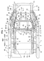
- FIG. 1 is a top plan view showing installation structure of a fuel cell stack system in a fuel cell vehicle.
- FIG. 2 is a side view of FIG.1.
- FIG. 3 is an A.A cross-sectional view in FIG. 1.
- a fuel cell stack and hydrogen tanks are installed in order from front (a forward side) under a floor.
- a rear floor 2 which forms a step rising in a rear direction (see FIG. 2) is attached to a rear edge of a front floor 1 to form the floor.
- a pair of left and right rear frames 13 and 14 are attached along a longitudinal direction under the rear floor 2.
- side sills 70 and 80 which are attached to side edges of the front floor 1 and floor frames 5 and 6 which are placed along the longitudinal direction between the side sills 70 and 80 are connected to front edges of the rear frames 13 and 14 through front brackets 11 and 12 respectively.
- a pair of left and right Y-shaped frames 43 and 43 are formed under the floor.
- a cross-member 4 (see FIG. 1) is attached in a reverse side of a step portion 3 of the rear floor 2 across a transverse direction of the vehicle.
- mainframes according to the present invention include the rear frames 13 and 14 and the floor frames 5 and 6.
- inside sills 7 and 8 are respectively connected to the left and right side edges of the front floor 1.
- Inside sill extensions 9 and 10 are respectively provided at rear ends of the inside sills 7 and 8.
- outside sills 7' and 8' are attached to the inside sills 7 and 8 so as to form the side sills 70 and 80.
- Rear brackets 17 and 18 whose cross-sections open upward (see FIG. 2) are respectively attached on lower sides of rear ends of the rear frames 13 and 14. Sidewalls of the rear brackets 17 and 18 are attached on outer surfaces of both sidewalls of the rear frames 13 and 14.
- color nuts 19 and 20 are vertically provided in front portions of the bottom walls of the rear brackets 17 and 18.
- cross-members 4A and 4B are respectively attached in front and back between the left and right rear frames 13 and 14 as shown in FIG. 1.
- a bumper beam 21 (see FIG. 1) is attached to their rear ends, more specifically, to rear ends of the rear brackets 17 and 18.
- a sub-frame 22 is fixed to color nuts 15, 16, 19, and 20 of the front brackets 11 and 12 and the rear brackets 17 and 18 using bolts 23, 23, 23, and 23 from underneath respectively.
- the sub-frame 22 is a substantially rectangular frame member formed of left and right frame members 24 and 25 and front and rear frame members 26 and 27. Moreover, the sub-frame 22 includes a cross beam 28 in the transverse direction of the vehicle. Thus, two hydrogen tanks 29 and 30 are respectively fastened with bands 31 and 32 in spaces divided by the cross beam 28 in order to be fixed to a car body.
- the hydrogen tanks 29 and 30 are placed parallel to the transverse direction of the vehicle and positioned at a height to keep a predetermined vertical space between the hydrogen tanks 29 and 30 and the rear floor 2.
- Suspension units 33 are attached to the sub-frame 22. And, a tire, which is not shown, is attached to each of the suspension units 33.
- insertion portions 34 and 35 for the bolts 23 and 23 which are inserted into the color nuts 15 and 16 are respectively provided at a corner between a front end of the left frame member 24 and a left end of the front frame member 26 and a corner between a front end of the right frame member 25 and a right end of the front frame member 26.
- insertion portions 36 and 37 for the bolts 23 and 23 which are inserted into the color nuts 19 and 20 are respectively provided at a corner between a rear end of the left frame member 24 and a left end of the rear frame member 27 and a corner between a rear end of the right frame member 25 and a right end of the rear frame member 27.
- the bolts 23, 23, 23, and 23 are respectively inserted into the insertion portions 34, 35, 36, and 37 of the sub-frame 22 configured in this way. Then, the bolts 23, 23, 23, and 23 are inserted and fastened into the color nuts 15, 16, 19, and 20 which are attached to the front brackets 11 and 12 and the rear brackets 17 and 18 of the rear frames 13 and 14 in order to fix the sub-frame 22 to the floor frames 5 and 6.
- a fuel cell box 39 is placed across the left and right floor frames 5 and 6 under the front floor 1.
- the fuel cell box 39 contains a fuel cell stack unit NU which includes a fuel cell stack 38 and peripheral equipments such as gas pipes.
- the fuel cell stack 38 generates electric power by electrochemical reaction of hydrogen supplied from the hydrogen tanks 29 and 30 and oxygen in air supplied from a compressor, which is not shown. Then, the fuel cell stack 38 supplies the generated electric power to a drive motor (not shown) placed in a front portion, which is not shown, of the car body to drive the fuel cell vehicle.
- the fuel cell box 39 includes a main case 39a and a lid 39b which cover the fuel cell stack unit NU. Moreover, the main case 39a and the lid 39b are fixed to bottom walls 5a and 6a of the floor frames 5 and 6 with bolts 40 and 40 being fastened into nuts 41 and 41 from underneath.
- a central pillar 71(81) is attached to the side sill 70(80).
- a bracket 42 is attached to each of six places on both sides with three places on each side, between the left floor frame 5 and the left side sill 70 and between the right floor frame 6 and the right side sill 80.
- the hydrogen tanks 29 and 30 are connected by a collection pipe 46 on the right side.
- a high-pressure pipe 47 which is connected to the collection pipe 46 goes along an inner surface of the frame member 25 of the sub-frame 22 and turns around to front of the front hydrogen tank 29. Then, the high-pressure pipe 47 goes along inner surface of the frame members 26 and 24 so as to be connected to a regulator 48 placed on the left side between both of the hydrogen tanks 29 and 30.
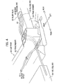
- a medium-pressure pipe 49 which extends forward from the regulator 48 is connected to a relief valve 50 which is attached on the frame member 24 as shown in FIG. 4.
- a downstream portion of the medium-pressure pipe 49 which is connected to the relief valve 50 goes astride and across both of the sub-frame 22 and the fuel cell box 39 within width of the both.
- the downstream portion of the medium-pressure pipe 49 is inserted and arranged in a crotch portion 44 which is a space formed by a left Y-shaped frame 43 on the left side, and then inserted into the fuel cell stack unit NU inside the fuel cell box 39 from a reverse side of a left rear portion of the fuel cell box 39.
- a release pipe 51 which is connected to the relief valve 50 goes along an outer surface of the frame member 26 which constructs the sub-frame 22, so as to be arranged in a space formed between the fuel cell box 39 and the sub-frame 22.
- a ventilation structure which takes in outside air is provided in the fuel cell box 39. Therefore, the fuel cell stack 38 is cooled while the outside air ventilates inside of the fuel cell box 39.
- High pressure hydrogen which is stored in the hydrogen tanks 29 and 30 is provided to the fuel cell stack unit NU through the high-pressure pipe 47 and the medium-pressure pipe 49.
- the regulator 48 decompresses hydrogen in the high-pressure pipe 47 to a predetermined pressure (for instance, 0.5MPa).
- a predetermined pressure for instance, 0.5MPa
- the hydrogen in the high-pressure pipe 47 which has not yet been decompressed enough may be poured into the medium-pressure pipe 49, for instance, caused by malfunction of a valve in the regulator 48. Consequently, the pressure of the hydrogen in the medium-pressure pipe 49 may reach a pressure (for instance, 0.8MPa) higher than the predetermined pressure.
- the relief valve 50 operates to release the hydrogen through the release pipe 51 and the release outlet 52.
- FIG. 5 is a drawing which shows a position where the release pipe of the relief valve is arranged, as well as the ventilation structure in the fuel cell box.
- a ventilating inlet 130 is provided on a right side in the transverse direction in a front wall 120 of the fuel cell box 39.
- the ventilating inlet 130 is connected to a fan 180 through an outside air introducing path (not shown).
- Ventilating outlets 150 and 150 of ventilation air which circulates inside the fuel cell box 39 are provided on both sides in the transverse direction in a rear wall 140 of the fuel cell box 39.
- exhaust ducts 160 and 160 are provided outside the rear wall 140 of the fuel cell box 39.
- the exhaust ducts 160 and 160 which extend inward in the transverse direction are respectively connected to the ventilating outlets 150 and 150.
- An exhaust outlet 170 which exhausts the ventilation air backward is provided to each of the exhaust ducts 160 in the vicinity of the center in the transverse direction.
- the exhaust outlet 170 of the exhaust duct 160 is provided at a position higher than an axis C of the hydrogen tanks 29 and 30.
- the release pipe 51 of the relief valve 50 extends to the vicinity of the exhaust outlet 170 of the exhaust duct 160 along the outer surface of the frame member 26 which faces the rear wall 140 of the fuel cell box 39, so that the release pipe 51 can be heated by hot air exhausted from the exhaust outlet 170.
- the release outlet 52 of the release pipe 51 is positioned substantially as high as the exhaust outlet 170, in other words, higher than the axis C of the hydrogen tanks 29 and 30.
- the release outlet 52 of the release pipe 51 points obliquely downward.
- the fan 180 introduces the outside air into the fuel cell box 39 from the ventilating inlet 130 through the outside air introducing path.
- the outside air forming a ventilation flow flows toward the ventilating outlets 150 and 150 which are provided on the both sides in the rear wall 140 of the fuel cell box 39 as indicated by a dashed arrow A in FIG. 5(a). Therefore, ventilation air circulates as if weaving through spaces on the left and right sides of the fuel cell stack 38.
- the ventilating inlet 130 is positioned lower than the ventilating outlets 150 and 150 in the vertical direction.
- the ventilation air also circulates as if weaving through spaces on the upper and lower sides of the fuel cell stack 38 as indicated by a dashed arrow B in FIG. 5(b).
- the ventilation air cools the fuel cell stack 38 by heat exchange while ventilating the fuel cell box 39.
- the ventilation air which has taken heat from the fuel cell stack 38 changes into warm exhaust air to be exhausted backward from the exhaust outlets 170 and 170.
- the two exhaust outlets 170 and 170 are positioned higher than the axis C of the hydrogen tanks 29 and 30 as shown in FIG. 5(b). Accordingly, the exhaust air from the exhaust outlets 170 and 170 flows toward the upper side of the hydrogen tanks 29 and 30. Therefore, a space between the hydrogen tanks 29 and 30 and the rear floor 2, where hydrogen is apt to be retained, is also ventilated.
- the release pipe 51 of the relief valve 50 is heated by radiant heat from the fuel cell box 39 since the release pipe 51 is provided in a space between the fuel cell box 39 and the frame member 26 of the sub-frame 22.
- the release pipe 51 is heated by the exhaust air when the exhaust air is exhausted from the exhaust outlets 170 and 170. Therefore, even when the release pipe 51 and the release outlet 52 are blocked by frozen snow or the like under low temperature conditions, starting the fuel cell vehicle generates heat of the fuel cell stack 38 so as to eliminate blocking of the release pipe 51 and the release outlet 52. As a result, it is possible to effectively prevent the relief valve 50 from not functioning caused by snow or ice even when the fuel cell vehicle is used under the low temperature conditions.
- the release outlet 52 of the release pipe 51 is heated by the heat of the fuel cell box 39 since the release outlet 52 of the release pipe 51 is provided in the space between the fuel cell box 39 and the frame member 26 of the sub-frame 22 and blocking by snow is unlikely to occur in the space. As a result, it is possible to effectively prevent the release outlet 52 from being blocked by snow or ice.
- a release outlet of hydrogen is required not to open directly to a passenger cabin or a trunk, not to open to a wheel house, not to face another container, not to face an electric terminal, and not to face forward.
- release pipe 51 and the release outlet 52 are placed between the floor frames 5 and 6 and the rear frames 13 and 14 which construct the mainframe, as well as between the fuel cell stack 38 and the hydrogen tanks 29 and 30, under the floor.
- none of electric wirings, other containers, and so on is provided under the floor. Therefore, hydrogen is not to be released from the release outlet toward components restricted by the technical standards.
- the release pipe and the release outlet of the relief valve have been described. And, the hydrogen in the hydrogen tanks is urgently released in abnormal conditions, for instance, high temperature in the hydrogen tanks 29 and 30.
- a release pipe and a release outlet of the emergency relief valve may be placed similar to the release pipe and the release outlet of the relief valve in the above-mentioned embodiment. As a result, it is possible to take an antifreeze measure similarly while complying with the technical standards.
- the present embodiment is not limited to this, and is also applicable to a fuel gas vehicle with a hydrogen fueled engine which uses high-pressure hydrogen, for instance.
- the fuel cell stack is replaced with the hydrogen fueled engine.
- outside air similarly circulates through the hydrogen fueled engine or a cooling mechanism so as to cool heat generated by the hydrogen fueled engine.
- a release pipe and a release outlet of a relief valve or an emergency relief valve are provided in a passage where the outside air circulates, so as to bring similar effects with those achieved by the present embodiment.
Landscapes
- Engineering & Computer Science (AREA)
- Life Sciences & Earth Sciences (AREA)
- Sustainable Development (AREA)
- Sustainable Energy (AREA)
- Chemical & Material Sciences (AREA)
- Mechanical Engineering (AREA)
- Transportation (AREA)
- Combustion & Propulsion (AREA)
- General Chemical & Material Sciences (AREA)
- Electrochemistry (AREA)
- Chemical Kinetics & Catalysis (AREA)
- Manufacturing & Machinery (AREA)
- Power Engineering (AREA)
- Fuel Cell (AREA)
- Cooling, Air Intake And Gas Exhaust, And Fuel Tank Arrangements In Propulsion Units (AREA)
- Body Structure For Vehicles (AREA)
- Arrangement Or Mounting Of Propulsion Units For Vehicles (AREA)
Abstract
Description
- The present invention relates to installation structure of a release pipe in a fuel cell vehicle and a fuel gas vehicle.
- In a fuel cell vehicle using high-pressure hydrogen, a safety valve is employed to release hydrogen to reduce pressure of hydrogen when temperature rises in a hydrogen tank where the high-pressure hydrogen is stored (See
JP 2002-206696A - In addition, a hydrogen burst generates large energy due to high pressure of the hydrogen when the hydrogen is released into the air. Therefore, in a well-known technology, a shielding member is provided in a release outlet to disperse the hydrogen so as to reduce outside influence (See
JP 2004-204956A - However, a vehicle is considered to be used under various conditions. For instance, a release outlet of a safety valve may be blocked caused by frozen snow, water, or the like when a fuel cell vehicle is used under low temperature conditions such as snowfalls. Nevertheless, no technology taking these conditions into consideration is disclosed in the conventional technologies described above. Therefore, even though a safety valve is employed, it is predicted that the safety valve does not function depending on position where a release outlet is placed.
- In view of the conventional problem described above, it is an object of the present invention to provide installation structure of a release pipe in a fuel cell vehicle and a fuel gas vehicle in order that a safety valve can surely function without a release outlet of the safety valve being blocked even under low temperature conditions.
- For this reason, according to the present invention, in a fuel cell vehicle having a hydrogen tank which stores hydrogen as fuel gas and a fuel cell stack which generates electric power using the hydrogen supplied from the hydrogen tank, the fuel cell stack and the hydrogen tank are arranged in order from front to back of the vehicle in such a manner that the fuel cell stack lies ahead of the hydrogen tank between left and right mainframes which extend in a longitudinal direction of the vehicle under a floor of the vehicle. In the fuel cell vehicle, a release pipe is provided to release the fuel gas in abnormal conditions. In addition, at least a release outlet of the release pipe is placed between the left and right mainframes and between the fuel cell stack and the hydrogen tank under the floor.
- None of electric wires, other containers, and so on is placed in an area between the left and the right mainframes and between the fuel cell stack and the hydrogen tank under the floor in the fuel cell vehicle. Therefore, the hydrogen is never released toward the electric wires, other containers, or the like. Moreover, this area is an area to which heat generated in the fuel cell stack is easily transferred so that the waste heat of the fuel cell stack can heat the release outlet.
- The present invention may further include a fuel cell box which contains at least the fuel cell stack, and a ventilation which ventilates hydrogen inside the fuel cell box. Thus, the ventilation may send ventilation air to rearward of the fuel cell box toward the release outlet.
- Accordingly, hydrogen leaked from the fuel cell stack can be also exhausted without being retained inside the fuel cell box. Moreover, the ventilation air can necessarily heat the release outlet.
- In the present invention, the release outlet may be placed in a higher position than a center axis of the hydrogen tank.
- Thus, when the ventilation sends ventilation air toward above of the center axis of the hydrogen tank, the release outlet can be efficiently heated.
- According to the present invention, in a fuel gas vehicle having a gas container which stores fuel gas, and an engine which generates power using the fuel gas supplied from the gas container, a release pipe is provided to release the fuel gas in abnormal conditions. In the fuel gas vehicle, at least a release outlet of the release pipe is placed in an area which is heated by the engine.
- Accordingly, heat generated in the engine can heat the release outlet of the release pipe.
- According to the present invention, heat generated in a fuel cell stack or an engine can heat a release outlet of a release pipe which releases fuel gas such as hydrogen in abnormal conditions so as to prevent the release outlet from being frozen and blocked caused by frozen snow, water, or the like.
-
- FIG. 1 is a top plan view showing installation structure of a fuel cell stack system in a fuel cell vehicle.
- FIG. 2 is a side view of FIG. 1.
- FIG. 3 is an A-A sectional view in FIG. 1.
- FIG. 4 is a perspective view showing positions where a release pipe and a release outlet are placed according to the present invention.
- FIG. 5 is a diagram showing the position where the release pipe of the relief valve is placed, as well as a ventilation structure in a fuel cell box.
- Here will be described an embodiment in a case where the present invention is applied to a fuel cell vehicle, below.
- FIG. 1 is a top plan view showing installation structure of a fuel cell stack system in a fuel cell vehicle. FIG. 2 is a side view of FIG.1. FIG. 3 is an A.A cross-sectional view in FIG. 1.
- In this installation structure, a fuel cell stack and hydrogen tanks are installed in order from front (a forward side) under a floor. As shown in FIGs. 1 and 2, a
rear floor 2 which forms a step rising in a rear direction (see FIG. 2) is attached to a rear edge of afront floor 1 to form the floor. - A pair of left and right
rear frames rear floor 2. In addition,side sills front floor 1 andfloor frames side sills rear frames front brackets shaped frames step portion 3 of therear floor 2 across a transverse direction of the vehicle. - Here, mainframes according to the present invention include the
rear frames floor frames - Moreover, inside
sills front floor 1. Insidesill extensions inside sills inside sills side sills -
Rear brackets rear frames rear brackets rear frames color nuts 19 and 20 (see FIG. 2) are vertically provided in front portions of the bottom walls of therear brackets - Moreover, two
cross-members 4A and 4B are respectively attached in front and back between the left and rightrear frames rear brackets - In addition, a
sub-frame 22 is fixed tocolor nuts front brackets rear brackets bolts - The
sub-frame 22 is a substantially rectangular frame member formed of left andright frame members rear frame members sub-frame 22 includes across beam 28 in the transverse direction of the vehicle. Thus, twohydrogen tanks bands cross beam 28 in order to be fixed to a car body. - The
hydrogen tanks hydrogen tanks rear floor 2. -
Suspension units 33 are attached to thesub-frame 22. And, a tire, which is not shown, is attached to each of thesuspension units 33. - In addition,
insertion portions 34 and 35 (see FIG. 1) for thebolts color nuts left frame member 24 and a left end of thefront frame member 26 and a corner between a front end of theright frame member 25 and a right end of thefront frame member 26. Then,insertion portions bolts color nuts left frame member 24 and a left end of therear frame member 27 and a corner between a rear end of theright frame member 25 and a right end of therear frame member 27. - Thus, the
bolts insertion portions sub-frame 22 configured in this way. Then, thebolts color nuts front brackets rear brackets sub-frame 22 to the floor frames 5 and 6. - A
fuel cell box 39 is placed across the left and right floor frames 5 and 6 under thefront floor 1. Thefuel cell box 39 contains a fuel cell stack unit NU which includes afuel cell stack 38 and peripheral equipments such as gas pipes. Thefuel cell stack 38 generates electric power by electrochemical reaction of hydrogen supplied from thehydrogen tanks fuel cell stack 38 supplies the generated electric power to a drive motor (not shown) placed in a front portion, which is not shown, of the car body to drive the fuel cell vehicle. - As shown in the A-A sectional view in FIG. 3, the
fuel cell box 39 includes amain case 39a and alid 39b which cover the fuel cell stack unit NU. Moreover, themain case 39a and thelid 39b are fixed tobottom walls bolts nuts bracket 42 is attached to each of six places on both sides with three places on each side, between theleft floor frame 5 and theleft side sill 70 and between theright floor frame 6 and theright side sill 80. - The
hydrogen tanks collection pipe 46 on the right side. A high-pressure pipe 47 which is connected to thecollection pipe 46 goes along an inner surface of theframe member 25 of thesub-frame 22 and turns around to front of thefront hydrogen tank 29. Then, the high-pressure pipe 47 goes along inner surface of theframe members regulator 48 placed on the left side between both of thehydrogen tanks pressure pipe 49 which extends forward from theregulator 48 is connected to arelief valve 50 which is attached on theframe member 24 as shown in FIG. 4. A downstream portion of the medium-pressure pipe 49 which is connected to therelief valve 50 goes astride and across both of thesub-frame 22 and thefuel cell box 39 within width of the both. Thus, the downstream portion of the medium-pressure pipe 49 is inserted and arranged in acrotch portion 44 which is a space formed by a left Y-shapedframe 43 on the left side, and then inserted into the fuel cell stack unit NU inside thefuel cell box 39 from a reverse side of a left rear portion of thefuel cell box 39. On the other hand, arelease pipe 51 which is connected to therelief valve 50 goes along an outer surface of theframe member 26 which constructs thesub-frame 22, so as to be arranged in a space formed between thefuel cell box 39 and thesub-frame 22. - A ventilation structure which takes in outside air is provided in the
fuel cell box 39. Therefore, thefuel cell stack 38 is cooled while the outside air ventilates inside of thefuel cell box 39. - High pressure hydrogen which is stored in the
hydrogen tanks pressure pipe 47 and the medium-pressure pipe 49. Theregulator 48 decompresses hydrogen in the high-pressure pipe 47 to a predetermined pressure (for instance, 0.5MPa). At this time, the hydrogen in the high-pressure pipe 47 which has not yet been decompressed enough may be poured into the medium-pressure pipe 49, for instance, caused by malfunction of a valve in theregulator 48. Consequently, the pressure of the hydrogen in the medium-pressure pipe 49 may reach a pressure (for instance, 0.8MPa) higher than the predetermined pressure. For example, in an abnormal condition where the pressure of the hydrogen in the medium-pressure pipe 49 becomes 2MPa or higher, therelief valve 50 operates to release the hydrogen through therelease pipe 51 and therelease outlet 52. - Next, how the
release pipe 51 and therelease outlet 52 of therelief valve 50 according to the present invention are arranged will be described referring to FIG. 5. - FIG. 5 is a drawing which shows a position where the release pipe of the relief valve is arranged, as well as the ventilation structure in the fuel cell box.
- As shown in FIG. 5, a ventilating
inlet 130 is provided on a right side in the transverse direction in afront wall 120 of thefuel cell box 39. The ventilatinginlet 130 is connected to afan 180 through an outside air introducing path (not shown). Ventilatingoutlets fuel cell box 39 are provided on both sides in the transverse direction in arear wall 140 of thefuel cell box 39. In addition,exhaust ducts rear wall 140 of thefuel cell box 39. Theexhaust ducts outlets exhaust outlet 170 which exhausts the ventilation air backward is provided to each of theexhaust ducts 160 in the vicinity of the center in the transverse direction. - As shown in FIG. 5(b), the
exhaust outlet 170 of theexhaust duct 160 is provided at a position higher than an axis C of thehydrogen tanks release pipe 51 of therelief valve 50 extends to the vicinity of theexhaust outlet 170 of theexhaust duct 160 along the outer surface of theframe member 26 which faces therear wall 140 of thefuel cell box 39, so that therelease pipe 51 can be heated by hot air exhausted from theexhaust outlet 170. As shown in FIG. 5(b), therelease outlet 52 of therelease pipe 51 is positioned substantially as high as theexhaust outlet 170, in other words, higher than the axis C of thehydrogen tanks release outlet 52 of therelease pipe 51 points obliquely downward. - When the
fuel cell stack 38 generates electricity, thefan 180 introduces the outside air into thefuel cell box 39 from the ventilatinginlet 130 through the outside air introducing path. The outside air forming a ventilation flow flows toward the ventilatingoutlets rear wall 140 of thefuel cell box 39 as indicated by a dashed arrow A in FIG. 5(a). Therefore, ventilation air circulates as if weaving through spaces on the left and right sides of thefuel cell stack 38. Moreover, the ventilatinginlet 130 is positioned lower than the ventilatingoutlets fuel cell stack 38 as indicated by a dashed arrow B in FIG. 5(b). - The ventilation air cools the
fuel cell stack 38 by heat exchange while ventilating thefuel cell box 39. The ventilation air which has taken heat from thefuel cell stack 38 changes into warm exhaust air to be exhausted backward from theexhaust outlets exhaust outlets hydrogen tanks exhaust outlets hydrogen tanks hydrogen tanks rear floor 2, where hydrogen is apt to be retained, is also ventilated. - The
release pipe 51 of therelief valve 50 is heated by radiant heat from thefuel cell box 39 since therelease pipe 51 is provided in a space between thefuel cell box 39 and theframe member 26 of thesub-frame 22. In addition, therelease pipe 51 is heated by the exhaust air when the exhaust air is exhausted from theexhaust outlets release pipe 51 and therelease outlet 52 are blocked by frozen snow or the like under low temperature conditions, starting the fuel cell vehicle generates heat of thefuel cell stack 38 so as to eliminate blocking of therelease pipe 51 and therelease outlet 52. As a result, it is possible to effectively prevent therelief valve 50 from not functioning caused by snow or ice even when the fuel cell vehicle is used under the low temperature conditions. - Furthermore, even in a case where the fuel cell vehicle whirls up snow while running, the
release outlet 52 of therelease pipe 51 is heated by the heat of thefuel cell box 39 since therelease outlet 52 of therelease pipe 51 is provided in the space between thefuel cell box 39 and theframe member 26 of thesub-frame 22 and blocking by snow is unlikely to occur in the space. As a result, it is possible to effectively prevent therelease outlet 52 from being blocked by snow or ice. - There are technical standards about usage of hydrogen, which are requested to apply to a fuel cell vehicle. According to the technical standards, for instance, a release outlet of hydrogen is required not to open directly to a passenger cabin or a trunk, not to open to a wheel house, not to face another container, not to face an electric terminal, and not to face forward. According to the present embodiment, it is possible to take an antifreeze measure while complying with the technical standards since the
release pipe 51 and therelease outlet 52 of therelief valve 50 are placed in the space between thefuel cell box 39 and theframe member 26 of thesub-frame 22. - In other words, a part of the
release pipe 51 and therelease outlet 52 are placed between the floor frames 5 and 6 and the rear frames 13 and 14 which construct the mainframe, as well as between thefuel cell stack 38 and thehydrogen tanks - In the above-mentioned embodiment, the release pipe and the release outlet of the relief valve have been described. And, the hydrogen in the hydrogen tanks is urgently released in abnormal conditions, for instance, high temperature in the
hydrogen tanks - In the present embodiment, description has been given to the antifreeze measure of the release pipe and the release outlet concerning to the fuel cell vehicle. However, the present embodiment is not limited to this, and is also applicable to a fuel gas vehicle with a hydrogen fueled engine which uses high-pressure hydrogen, for instance. In this case, the fuel cell stack is replaced with the hydrogen fueled engine. In addition, outside air similarly circulates through the hydrogen fueled engine or a cooling mechanism so as to cool heat generated by the hydrogen fueled engine. Then, a release pipe and a release outlet of a relief valve or an emergency relief valve are provided in a passage where the outside air circulates, so as to bring similar effects with those achieved by the present embodiment.
Claims (4)
- An installation structure of a release pipe in a fuel cell vehicle having a hydrogen tank which stores hydrogen as fuel gas and a fuel cell stack which generates electric power using the hydrogen supplied from the hydrogen tank, the fuel cell stack and the hydrogen tank being arranged in order from front to back of the vehicle in such a manner that the fuel cell stack lies ahead of the hydrogen tank between left and right mainframes which extend in a longitudinal direction of the vehicle under a floor of the vehicle, wherein
the release pipe is provided to release the fuel gas in abnormal conditions, and wherein
at least a release outlet of the release pipe is placed between the left and right mainframes and between the fuel cell stack and the hydrogen tank under the floor. - An installation structure of a release pipe in a fuel cell vehicle as claimed in claim 1, further comprising:a fuel cell box which contains at least the fuel cell stack; anda ventilation which ventilates hydrogen inside the fuel cell box; wherein the ventilation sends ventilation air to rearward of the fuel cell box toward the release outlet.
- An installation structure of a release pipe in a fuel cell vehicle as claimed in either one of claim 1 or 2, wherein the release outlet is placed in a higher position than a center axis of the hydrogen tank.
- An installation structure of a release pipe in a fuel gas vehicle having a gas container which stores fuel gas, and an engine which generates power using the fuel gas supplied from the gas container, wherein
the release pipe is provided to release the fuel gas in abnormal conditions, and wherein
at least a release outlet of the release pipe is placed in an area which is heated by the engine.
Applications Claiming Priority (2)
| Application Number | Priority Date | Filing Date | Title |
|---|---|---|---|
| JP2004347911A JP4383327B2 (en) | 2004-11-30 | 2004-11-30 | Release tube mounting structure for fuel cell vehicle and gas fuel vehicle |
| PCT/JP2005/021886 WO2006059599A1 (en) | 2004-11-30 | 2005-11-29 | Fuel cell automobile and release tube installation structure for gas fuel automobile |
Publications (3)
| Publication Number | Publication Date |
|---|---|
| EP1818204A1 true EP1818204A1 (en) | 2007-08-15 |
| EP1818204A4 EP1818204A4 (en) | 2008-11-05 |
| EP1818204B1 EP1818204B1 (en) | 2012-07-11 |
Family
ID=36565033
Family Applications (1)
| Application Number | Title | Priority Date | Filing Date |
|---|---|---|---|
| EP05811414A Expired - Lifetime EP1818204B1 (en) | 2004-11-30 | 2005-11-29 | Fuel cell automobile and release tube installation structure for gas fuel automobile |
Country Status (7)
| Country | Link |
|---|---|
| US (1) | US7770679B2 (en) |
| EP (1) | EP1818204B1 (en) |
| JP (1) | JP4383327B2 (en) |
| KR (1) | KR100806965B1 (en) |
| CN (1) | CN100532148C (en) |
| CA (1) | CA2551799C (en) |
| WO (1) | WO2006059599A1 (en) |
Families Citing this family (44)
| Publication number | Priority date | Publication date | Assignee | Title |
|---|---|---|---|---|
| FR2874247B1 (en) * | 2004-08-12 | 2007-03-16 | Air Liquide | GAS STORAGE SYSTEM, METHOD OF IMPLEMENTATION AND VEHICLE INCORPORATING SUCH A SYSTEM |
| JP4928087B2 (en) * | 2005-03-14 | 2012-05-09 | ヤンマー株式会社 | Work vehicle frame structure |
| DE102007001912A1 (en) * | 2007-01-12 | 2008-07-17 | Airbus Deutschland Gmbh | Fuel supply system for a fuel cell system |
| JP4225363B2 (en) * | 2007-07-24 | 2009-02-18 | トヨタ自動車株式会社 | Vehicle equipped with internal combustion engine and rotating electric machine as power source |
| US8053127B2 (en) * | 2008-04-23 | 2011-11-08 | GM Global Technology Operations LLC | Fuel cell cooling tank assembly |
| JP5262466B2 (en) * | 2008-09-04 | 2013-08-14 | 株式会社豊田自動織機 | Fuel cell vehicle |
| JP5251459B2 (en) * | 2008-11-28 | 2013-07-31 | トヨタ自動車株式会社 | Fuel cell vehicle |
| JP5375274B2 (en) * | 2009-04-01 | 2013-12-25 | トヨタ自動車株式会社 | Hydrogen supply system for fuel cell vehicles |
| DE112009004806B4 (en) * | 2009-05-28 | 2018-03-22 | Toyota Jidosha Kabushiki Kaisha | Fuel cell system and vehicle |
| WO2010150386A1 (en) | 2009-06-25 | 2010-12-29 | トヨタ自動車株式会社 | Hybrid vehicle structure |
| US7913788B1 (en) * | 2010-02-09 | 2011-03-29 | Gm Global Technology Operations, Llc | Integrated energy storage and rear suspension assembly |
| JP2011194954A (en) * | 2010-03-18 | 2011-10-06 | Toyota Motor Corp | Fuel-cell-powered vehicle |
| JP5459131B2 (en) * | 2010-07-26 | 2014-04-02 | スズキ株式会社 | Air-cooled fuel cell vehicle |
| JP5440452B2 (en) | 2010-08-31 | 2014-03-12 | スズキ株式会社 | Fuel cell system |
| JP5585378B2 (en) * | 2010-10-21 | 2014-09-10 | スズキ株式会社 | Air-cooled fuel cell vehicle |
| JP5641340B2 (en) * | 2011-03-04 | 2014-12-17 | スズキ株式会社 | Intake device for fuel cell vehicle |
| JP5652719B2 (en) * | 2011-05-02 | 2015-01-14 | スズキ株式会社 | Fuel cell vehicle |
| JP5141795B2 (en) * | 2011-06-20 | 2013-02-13 | 株式会社豊田自動織機 | Battery unit mounting device for vehicle |
| JP5983063B2 (en) * | 2012-06-08 | 2016-08-31 | スズキ株式会社 | In-vehicle structure of battery pack |
| JP5962610B2 (en) * | 2013-08-01 | 2016-08-03 | トヨタ自動車株式会社 | Vehicle rear structure |
| KR101527047B1 (en) * | 2013-12-30 | 2015-06-09 | 현대자동차주식회사 | Modularized structure of rear suspension |
| JP6104864B2 (en) * | 2014-09-02 | 2017-03-29 | 本田技研工業株式会社 | Fuel cell stack and fuel cell vehicle |
| US10081243B2 (en) | 2015-05-03 | 2018-09-25 | Natural Gas Fuel Systems, Inc. | Apparatuses for mounting tanks to vehicles and related methods |
| JP6144303B2 (en) * | 2015-08-27 | 2017-06-07 | 本田技研工業株式会社 | Fuel cell vehicle |
| DE102015224243A1 (en) * | 2015-12-03 | 2017-06-08 | Bayerische Motoren Werke Aktiengesellschaft | Motor vehicle with at least two tanks for receiving fuel under high pressure |
| EP3436323A1 (en) * | 2016-04-01 | 2019-02-06 | Agility Fuel Systems LLC | Vehicle fluid handling systems |
| JP6311744B2 (en) * | 2016-06-06 | 2018-04-18 | トヨタ自動車株式会社 | Air-cooled fuel cell vehicle |
| CN106828067A (en) * | 2017-01-05 | 2017-06-13 | 北京新能源汽车股份有限公司 | Fuel cell electric vehicle |
| KR102603361B1 (en) * | 2017-06-30 | 2023-11-16 | 플라스틱 옴니엄 뉴 에너지스 프랑스 | fuel cell architecture |
| JP6907913B2 (en) * | 2017-12-08 | 2021-07-21 | トヨタ自動車株式会社 | Fuel cell vehicle |
| JP7096687B2 (en) * | 2018-03-28 | 2022-07-06 | 大阪瓦斯株式会社 | Fuel cell system |
| JP2020093771A (en) * | 2018-12-11 | 2020-06-18 | 豊田合成株式会社 | Electric vehicle and energy package |
| JP6843898B2 (en) * | 2019-01-11 | 2021-03-17 | 本田技研工業株式会社 | Vehicle with high pressure gas container |
| US11440399B2 (en) | 2019-03-22 | 2022-09-13 | Agility Fuel Systems Llc | Fuel system mountable to a vehicle frame |
| US20200347992A1 (en) | 2019-05-02 | 2020-11-05 | Agility Fuel Systems Llc | Polymeric liner based gas cylinder with reduced permeability |
| CN110525203A (en) * | 2019-08-16 | 2019-12-03 | 武汉格罗夫氢能汽车有限公司 | A kind of hydrogen energy automobile hydrogen quick air releasing device |
| TWI709278B (en) * | 2019-08-20 | 2020-11-01 | 元智大學 | A gas pressure reducing device, a fuel cell system and an electric vehicle |
| CN111993893B (en) * | 2020-06-19 | 2021-11-12 | 嘉兴学院 | Vehicle-mounted hydrogen safety system and method with solar intelligent power supply |
| CN112977053B (en) * | 2020-09-22 | 2021-12-10 | 北汽福田汽车股份有限公司 | Vehicle with a steering wheel |
| JP7200198B2 (en) * | 2020-12-03 | 2023-01-06 | 本田技研工業株式会社 | fuel cell vehicle |
| EP4588711A1 (en) | 2022-09-15 | 2025-07-23 | Obshchestvo s Ogranichennoi Otvetstvennostiu "Evokargo" | Fuel storage and supply system for vehicle fuel cells |
| JP7831277B2 (en) * | 2022-12-26 | 2026-03-17 | トヨタ自動車株式会社 | Fuel cell vehicles |
| DE102023202382A1 (en) * | 2023-03-16 | 2024-09-19 | Robert Bosch Gesellschaft mit beschränkter Haftung | Method for operating a fuel gas tank system, control device |
| DE102023208419A1 (en) * | 2023-09-01 | 2025-03-06 | Stellantis Auto Sas | FUEL CELL UNIT |
Family Cites Families (33)
| Publication number | Priority date | Publication date | Assignee | Title |
|---|---|---|---|---|
| JPH03109126A (en) * | 1989-09-21 | 1991-05-09 | Yamaha Motor Co Ltd | Electric automobile using fuel battery |
| JP3125198B2 (en) * | 1991-12-04 | 2001-01-15 | 本田技研工業株式会社 | Battery temperature control device for electric vehicle |
| US5392873A (en) * | 1992-01-22 | 1995-02-28 | Honda Giken Kogyo Kabushiki Kaisha | Structure for securing batteries used in an electric vehicle |
| US5237981A (en) * | 1992-02-21 | 1993-08-24 | Pas, Inc. | Fuel injection apparatus for vehicles |
| JP3044975B2 (en) * | 1992-12-10 | 2000-05-22 | トヨタ自動車株式会社 | Battery heating device for electric vehicles |
| US5443578A (en) * | 1993-05-17 | 1995-08-22 | Davis, Jr.; William F. | Compressed natural gas fuel tank for vehicles |
| DE4412450A1 (en) * | 1994-04-12 | 1995-10-26 | Daimler Benz Ag | Arrangement of a drive unit in an electric vehicle |
| US5673939A (en) * | 1995-09-20 | 1997-10-07 | The Babcock & Wilcox Company | Fuel tank for storing and dispensing hydrogen and oxygen gas to a fuel cell |
| DE10026268A1 (en) * | 1999-05-28 | 2000-12-07 | Honda Motor Co Ltd | Fuel cell powered electric vehicle has fuel tank, fuel reformer, fuel cell, electrical energy storage device arranged in series in longitudinal vehicle direction below floor of vehicle |
| JP2002165309A (en) * | 2000-11-20 | 2002-06-07 | Honda Motor Co Ltd | Fuel cell four-wheeled vehicle |
| JP3771441B2 (en) * | 2000-12-05 | 2006-04-26 | 本田技研工業株式会社 | Fuel cell vehicle |
| DE10065305A1 (en) | 2000-12-29 | 2002-07-18 | Siemens Ag | Motor vehicle with an internal combustion engine and an on-board power supply |
| JP2002206696A (en) * | 2001-01-09 | 2002-07-26 | Honda Motor Co Ltd | High pressure gas supply system |
| JP4298940B2 (en) * | 2001-08-31 | 2009-07-22 | 本田技研工業株式会社 | Car body rear structure |
| JP3932185B2 (en) * | 2001-09-26 | 2007-06-20 | 本田技研工業株式会社 | Fuel cell mounted electric vehicle and fuel cell system box |
| JP4007538B2 (en) * | 2002-01-08 | 2007-11-14 | 本田技研工業株式会社 | Gas fuel supply device |
| JP3908073B2 (en) * | 2002-04-05 | 2007-04-25 | 本田技研工業株式会社 | Exhaust pipe structure of a fuel cell vehicle |
| EP1717083B1 (en) * | 2002-06-10 | 2008-12-10 | Toyota Jidosha Kabushiki Kaisha | Fuel cell vehicle |
| JP2004026008A (en) * | 2002-06-25 | 2004-01-29 | Honda Motor Co Ltd | Fuel cell electric vehicle |
| JP4094357B2 (en) * | 2002-07-02 | 2008-06-04 | 本田技研工業株式会社 | Fuel cell vehicle body structure |
| JP4083506B2 (en) * | 2002-08-23 | 2008-04-30 | 本田技研工業株式会社 | Fuel cell vehicle |
| JP4445190B2 (en) * | 2002-09-10 | 2010-04-07 | 本田技研工業株式会社 | Gas fuel supply device |
| US7303033B2 (en) * | 2002-10-10 | 2007-12-04 | General Motors Corporation | Vehicle frame assembly and method for same |
| JP3977231B2 (en) * | 2002-11-11 | 2007-09-19 | 本田技研工業株式会社 | Ventilation structure of fuel cell vehicle |
| JP3746758B2 (en) * | 2002-11-11 | 2006-02-15 | 本田技研工業株式会社 | Piping structure for fuel cell vehicles |
| JP2004168101A (en) * | 2002-11-18 | 2004-06-17 | Honda Motor Co Ltd | Electric vehicle with fuel cell |
| JP2004187485A (en) * | 2002-12-02 | 2004-07-02 | Yamaha Motor Co Ltd | Electric vehicle |
| JP2004204956A (en) * | 2002-12-25 | 2004-07-22 | Nissan Motor Co Ltd | High pressure fuel gas storage device |
| US20040149500A1 (en) * | 2003-02-05 | 2004-08-05 | Chernoff Adrian B. | Pre-engineered frame portion and method of use therefor |
| JP4082597B2 (en) * | 2003-07-11 | 2008-04-30 | 本田技研工業株式会社 | Fuel cell vehicle |
| JP4081430B2 (en) * | 2003-11-19 | 2008-04-23 | 本田技研工業株式会社 | Fuel cell vehicle |
| JP4826072B2 (en) * | 2004-07-29 | 2011-11-30 | 日産自動車株式会社 | Fuel cell vehicle |
| JP4549826B2 (en) * | 2004-11-26 | 2010-09-22 | 本田技研工業株式会社 | Fuel cell vehicle |
-
2004
- 2004-11-30 JP JP2004347911A patent/JP4383327B2/en not_active Expired - Fee Related
-
2005
- 2005-11-29 CA CA002551799A patent/CA2551799C/en not_active Expired - Fee Related
- 2005-11-29 CN CNB2005800033644A patent/CN100532148C/en not_active Expired - Fee Related
- 2005-11-29 WO PCT/JP2005/021886 patent/WO2006059599A1/en not_active Ceased
- 2005-11-29 EP EP05811414A patent/EP1818204B1/en not_active Expired - Lifetime
- 2005-11-29 US US10/584,999 patent/US7770679B2/en active Active
- 2005-11-29 KR KR1020067012974A patent/KR100806965B1/en not_active Expired - Fee Related
Also Published As
| Publication number | Publication date |
|---|---|
| CN1914057A (en) | 2007-02-14 |
| CN100532148C (en) | 2009-08-26 |
| US7770679B2 (en) | 2010-08-10 |
| JP4383327B2 (en) | 2009-12-16 |
| KR100806965B1 (en) | 2008-02-22 |
| KR20070046020A (en) | 2007-05-02 |
| EP1818204B1 (en) | 2012-07-11 |
| JP2006151303A (en) | 2006-06-15 |
| WO2006059599A1 (en) | 2006-06-08 |
| US20090025989A1 (en) | 2009-01-29 |
| CA2551799C (en) | 2008-09-30 |
| EP1818204A4 (en) | 2008-11-05 |
| CA2551799A1 (en) | 2006-06-08 |
Similar Documents
| Publication | Publication Date | Title |
|---|---|---|
| CA2551799C (en) | Installation structure of release pipe in fuel cell vehicle and fuel gas vehicle | |
| JP3932185B2 (en) | Fuel cell mounted electric vehicle and fuel cell system box | |
| EP1182721B1 (en) | Thermal management system for an electrochemical engine | |
| US6378637B1 (en) | Fuel-cell-powered electric automobile | |
| US7896115B2 (en) | Fuel cell vehicle | |
| JP4594107B2 (en) | Bus-type vehicle | |
| US7481288B2 (en) | Cooling Arrangement for a fuel-cell vehicle | |
| JP4644034B2 (en) | Cooling device for fuel cell vehicle | |
| CN107776387A (en) | Vehicle | |
| US20080006461A1 (en) | Vehicle | |
| JP2009018803A (en) | vehicle | |
| EP4431327B1 (en) | Cooling device for fuel cell vehicle | |
| JP4023450B2 (en) | Cooling device for electrical equipment | |
| JP2004196217A (en) | Fuel cell vehicle | |
| CA2787237A1 (en) | Fuel-cell-powered vehicle | |
| JP4506254B2 (en) | Fuel cell system mounting structure on vehicle | |
| US20200161677A1 (en) | Fuel cell system | |
| EP2212530B1 (en) | Cooling arrangement for a utility vehicle | |
| US20210273279A1 (en) | Module for a Motor Vehicle | |
| CN117177873A (en) | Vehicles equipped with improved aerodynamic systems | |
| JP2014043225A (en) | Cooling structure of vehicle battery pack | |
| CN113104113A (en) | Tractor truck chassis platform and tractor truck suitable for fuel cell | |
| CN106394215A (en) | Vehicle | |
| JP2009035044A (en) | Saddle riding vehicle | |
| WO2006073191A1 (en) | Vehicle |
Legal Events
| Date | Code | Title | Description |
|---|---|---|---|
| PUAI | Public reference made under article 153(3) epc to a published international application that has entered the european phase |
Free format text: ORIGINAL CODE: 0009012 |
|
| 17P | Request for examination filed |
Effective date: 20060630 |
|
| AK | Designated contracting states |
Kind code of ref document: A1 Designated state(s): DE FR GB IT |
|
| DAX | Request for extension of the european patent (deleted) | ||
| RBV | Designated contracting states (corrected) |
Designated state(s): DE FR GB IT |
|
| RIC1 | Information provided on ipc code assigned before grant |
Ipc: B60K 11/06 20060101ALI20080924BHEP Ipc: B60L 11/18 20060101ALI20080924BHEP Ipc: B60K 8/00 20060101AFI20060613BHEP Ipc: H01M 8/04 20060101ALI20080924BHEP Ipc: F17C 13/04 20060101ALI20080924BHEP Ipc: B60K 1/04 20060101ALI20080924BHEP |
|
| A4 | Supplementary search report drawn up and despatched |
Effective date: 20081002 |
|
| 17Q | First examination report despatched |
Effective date: 20090210 |
|
| 17Q | First examination report despatched |
Effective date: 20110504 |
|
| GRAP | Despatch of communication of intention to grant a patent |
Free format text: ORIGINAL CODE: EPIDOSNIGR1 |
|
| GRAS | Grant fee paid |
Free format text: ORIGINAL CODE: EPIDOSNIGR3 |
|
| RIN1 | Information on inventor provided before grant (corrected) |
Inventor name: TOGASAWA, SHUICHI C/O HONDA R & D CO., LTD. Inventor name: MIURA, KENTARO C/O HONDA R & D CO., LTD. Inventor name: TAKAKU, KOICHI C/O HONDA R & D CO., LTD. |
|
| GRAA | (expected) grant |
Free format text: ORIGINAL CODE: 0009210 |
|
| AK | Designated contracting states |
Kind code of ref document: B1 Designated state(s): DE FR GB IT |
|
| REG | Reference to a national code |
Ref country code: GB Ref legal event code: FG4D |
|
| REG | Reference to a national code |
Ref country code: DE Ref legal event code: R096 Ref document number: 602005035165 Country of ref document: DE Effective date: 20120906 |
|
| PLBE | No opposition filed within time limit |
Free format text: ORIGINAL CODE: 0009261 |
|
| STAA | Information on the status of an ep patent application or granted ep patent |
Free format text: STATUS: NO OPPOSITION FILED WITHIN TIME LIMIT |
|
| PG25 | Lapsed in a contracting state [announced via postgrant information from national office to epo] |
Ref country code: IT Free format text: LAPSE BECAUSE OF FAILURE TO SUBMIT A TRANSLATION OF THE DESCRIPTION OR TO PAY THE FEE WITHIN THE PRESCRIBED TIME-LIMIT Effective date: 20120711 |
|
| 26N | No opposition filed |
Effective date: 20130412 |
|
| GBPC | Gb: european patent ceased through non-payment of renewal fee |
Effective date: 20121129 |
|
| REG | Reference to a national code |
Ref country code: DE Ref legal event code: R097 Ref document number: 602005035165 Country of ref document: DE Effective date: 20130412 |
|
| REG | Reference to a national code |
Ref country code: FR Ref legal event code: ST Effective date: 20130731 |
|
| PG25 | Lapsed in a contracting state [announced via postgrant information from national office to epo] |
Ref country code: FR Free format text: LAPSE BECAUSE OF NON-PAYMENT OF DUE FEES Effective date: 20121130 Ref country code: GB Free format text: LAPSE BECAUSE OF NON-PAYMENT OF DUE FEES Effective date: 20121129 |
|
| PGFP | Annual fee paid to national office [announced via postgrant information from national office to epo] |
Ref country code: DE Payment date: 20131127 Year of fee payment: 9 |
|
| REG | Reference to a national code |
Ref country code: DE Ref legal event code: R119 Ref document number: 602005035165 Country of ref document: DE |
|
| PG25 | Lapsed in a contracting state [announced via postgrant information from national office to epo] |
Ref country code: DE Free format text: LAPSE BECAUSE OF NON-PAYMENT OF DUE FEES Effective date: 20150602 |