EP1817856B1 - Interference characterisation and removal - Google Patents
Interference characterisation and removal Download PDFInfo
- Publication number
- EP1817856B1 EP1817856B1 EP05810705A EP05810705A EP1817856B1 EP 1817856 B1 EP1817856 B1 EP 1817856B1 EP 05810705 A EP05810705 A EP 05810705A EP 05810705 A EP05810705 A EP 05810705A EP 1817856 B1 EP1817856 B1 EP 1817856B1
- Authority
- EP
- European Patent Office
- Prior art keywords
- code
- codes
- tree
- received signal
- signal
- Prior art date
- Legal status (The legal status is an assumption and is not a legal conclusion. Google has not performed a legal analysis and makes no representation as to the accuracy of the status listed.)
- Not-in-force
Links
Images


Classifications
-
- H—ELECTRICITY
- H04—ELECTRIC COMMUNICATION TECHNIQUE
- H04J—MULTIPLEX COMMUNICATION
- H04J13/00—Code division multiplex systems
- H04J13/16—Code allocation
- H04J13/18—Allocation of orthogonal codes
- H04J13/20—Allocation of orthogonal codes having an orthogonal variable spreading factor [OVSF]
-
- H—ELECTRICITY
- H04—ELECTRIC COMMUNICATION TECHNIQUE
- H04J—MULTIPLEX COMMUNICATION
- H04J13/00—Code division multiplex systems
- H04J13/0007—Code type
- H04J13/004—Orthogonal
- H04J13/0044—OVSF [orthogonal variable spreading factor]
-
- H—ELECTRICITY
- H04—ELECTRIC COMMUNICATION TECHNIQUE
- H04B—TRANSMISSION
- H04B1/00—Details of transmission systems, not covered by a single one of groups H04B3/00 - H04B13/00; Details of transmission systems not characterised by the medium used for transmission
- H04B1/69—Spread spectrum techniques
- H04B1/707—Spread spectrum techniques using direct sequence modulation
- H04B1/7097—Interference-related aspects
- H04B1/7103—Interference-related aspects the interference being multiple access interference
Definitions
- This invention can be used to reduce interference that hampers the performance of User Equipment (UE) receivers in CDMA systems that employ Orthogonal Variable Spreading Factor (OVSF) codes (see, for example, 3GPP TS 25.213, Spreading and modulation (FDD), Release 5).
- OVSF Orthogonal Variable Spreading Factor
- Interference is a major problem for CDMA systems, the capacity of the system is directly related to the level of interference in it. It is clear that by reducing the amount of interference in the CDMA system, it is possible to improve its performance.
- OVSF codes are designed so that in an ideal environment time synchronised signals that have been spread with OVSF codes do not interfere with each other.
- time synchronised signals that have been spread with OVSF codes do not interfere with each other.
- orthogonality of these codes is never perfect because:
- MIMO Multiple-Input Multiple-Output
- JD Joint Detection
- MUD Multi-User Detection
- MUD techniques are typically not used in the UE receiver in the downlink because the UE does not have the knowledge of other users' spreading codes. In most systems the number of available spreading codes is so large that an exhaustive search using all of them is not possible in UE receivers which have limited power and processing capacities. For example in the 3GPP FDD system downlink it is possible to use spreading factors 4, 8, 16, 32, 64, 128, 256, and 512. This means that there are 1020 different spreading codes that could be in use. Another reason why MUD is not widely studied in the downlink is that most systems, such as UMTS with its OVSF codes, are designed so that in theory there is no such interference in the downlink a MUD scheme could remove. However, as shown earlier, this is not true in practice.
- US2002/154615 A1 discloses a detection method in which a CDMA-coded data signal is transmitted in the form of a data stream of spread data bursts between a transmitter and a receiver, hierarchical CDMA code being used for the transmissions.
- a first step of the detection method codes having a smaller spreading factor than a maximally to be detected spreading factor are detected.
- codes having a larger spreading factor than in the previous step are detected, the detection results in the first step being taken into account.
- the detection process is broken off if all codes are detected or otherwise the second step is repeated with the detection results last obtained in each instance until all codes are detected.
- the invention provides a method of evaluating the usage in a received signal of codes from a tree of codes that can be used to orthogonalise communications signals, the method comprising testing to determine if a given code is in use in the received signal and deducing from the result and from the tree structure the need to test in the received signal for the use of codes in the portion of the tree depending from said given code, characterised in that the method further comprises concluding that all codes in said portion are blocked from use if said given code is determined to be in use.
- the codes in the tree are OVSF codes.
- the code under test is tested by being correlated with the received signal in order to determine whether that code is used in the received signal.
- the tree structure permits the deduction of whether the codes in the portion of the tree depending from the code under test are blocked from use in the received signal.
- the tree structure permits the deduction of whether the codes in the portion of the tree depending from the code under test are unused. Such a deduction can be made with assistance from, for example, knowledge of the power levels associated with different layers of the tree.
- a tested code that is deemed to be used in the received signal is used to subtract from the received signal that part of the received signal that is attributable to that code. This can assist with, for example, interference cancellation in the case where the code under test is a potential interferer of another code that is known to be used in the received signal and that is desired to be demodulated.
- the method continues with the testing of other codes in the tree, to ascertain whether those codes are in use in the received signal.
- the testing of the further codes need not comprehend the testing of any subtrees for which testing has been deemed unnecessary and, moreover, the testing of the further codes can give rise to the identification, in the same manner as before, of further subtrees that do not require testing.
- the method described above can be performed by dedicated hardware (such as an ASIC) or by programmable or configurable hardware (such as a general purpose data processor or an FPGA).
- programmable or configurable hardware such as a general purpose data processor or an FPGA.
- the invention also consists in software for causing data processing equipment to perform the methods described above.
- the present invention provides a method which has the potential to enable a UE receiver to efficiently identify interfering spreading codes using the knowledge of the underlying code structure, and to remove the interference these codes cause in the receiver.
- This method has the potential to significantly improve the performance of UE receivers in CDMA systems, and especially in MIMO systems where there is large amount of noise caused by orthogonal codes.
- OVSF spreading codes are arranged in a tree structure. This tree consists of nodes and each node details one spreading code. Each node has one parent, and two branches. These branches can also be seen as their own subtrees.
- the spreading codes in this tree structure are arranged in such a way that higher codes "mask" their own subtrees. For example (see Figure 1 ), if code (8,2) is assigned to a user, it will not be possible to use codes (16,4) and (16,5) (or any code from their respective subtrees) simultaneously in the same cell, because those codes would not be orthogonal with code (8,2). Also, all parents of code (8,2) are blocked from use.
- the blocked codes are unusable because they are not orthogonal with the assigned code. This means that if any of those codes is used simultaneously with the assigned code, the resulting data streams will severely interfere with each other.
- the receiver correlates the received signal with the correct spreading code, the result is the original signal. If the receiver correlates the received signal with a different (but still orthogonal) spreading code, the result is zero, assuming that the signal has not been distorted too much by interference. However, if the receiver correlates the received signal with a different code that is non-orthogonal with the correct code, then the result is non-zero, and the power level of the correlator output depends on how populated the subtree is with interfering codes.
- the system power budget in the downlink is allocated in principle in a way which guarantees all bits an equal energy level over the interference flow, i.e., E b / I o should be constant
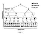
- the proposed scheme identifies the interfering codes by recursive walk-through of the code space.
- the idea is depicted in Figure 2 .
- the found interfering codes are used to regenerate the interfering signals, and these are then subtracted from the composite signal resulting in a signal with much less interference.
- FIG. 3 A flow chart of the code testing and interference removal scheme is depicted in Figure 3 .
- the unknown codes used on a link are identified at the receiver by a recursive walk-through of the code space. Possible spreading codes are tested in the correlator one-by-one. If the tested code is identified as an interferer, it is marked as a used code and its whole code sub-tree is marked as blocked. This walk-through the code space is started from a low-spreading factor and continued until all codes are tested, are found to be blocked, or are known to be unused. The number of codes the correlator has to check is manageable, because:
- step 10 a starting value for SF is chosen.
- the value SF is the spreading factor and dictates the horizontal layer of the code tree at which the walk-through starts.
- Steps 12 and 14 control the progress of the walk-through of each code tree layer that is to be tested.
- the parameters SF and SC correspond to the parameters m and n mentioned in the introductory portion of this specification.
- step 16 a decision is taken as to whether the process has reached the end of a layer of the code tree. If the end of such a layer is deemed to have been reached, the process moves to step 18 in which the process is moved down to the next layer of the code tree.
- Step 20 tests whether the final layer of the code tree has been processed.
- Steps 22 to 36 describe procedures that are performed during the testing of a node of the code tree and will now be discussed in greater detail.
- Step 22 tests whether the OVSF code of the node under test is already marked as a blocked code by virtue of a code higher up the tree being marked as a used code.
- Step 24 tests whether the OVSF code of the node under test has been specifically marked as unused during the testing of a node further up the code tree.
- the signal that is scheduled for interference reduction is correlated with the OVSF code of the node under test.
- Steps 28 and 30 evaluate the burst power of the result of that correlation process. In step 28, if the burst power of the correlation result is approximately nil, then the node and the nodes of any subtree depending from it are marked as unused OVSF codes.
- step 30 the burst power of the correlation result is compared with the burst power that is to be expected for a used spreading code in the current layer of the code tree. If the burst power of the correlation result is approximately the same as the burst power that would be expected of a used code at the current level of the code tree, then the spreading code at the node under test is deemed to be a used code and all codes in the subtree depending from the code under test are deemed to be blocked codes.
- step 36 the portion of the signal undergoing interference cancellation that is attributable to the spread spectrum signal using the OVSF code of the node under test is subtracted from the signal undergoing interference cancellation.
- the proposed code search algorithm enables the use of multi-user detection techniques in the synchronous CDMA downlink. This is advantageous because it enables very efficient interference reduction in the UE receiver, and therefore improves its performance.
- the proposed interference characterisation and removal scheme is especially advantageous in high interference environments such as in MIMO systems, where it can increase the data throughput considerably.
- the complexity is reduced by arranging that the code search algorithm ignores high SF spreading codes, such as 128, 256, and 512, because they will cause less interference than low SF spreading codes.
- the receiver can identify the codes from an SF under test as interfering codes if their correlator output results in a burst which has a power level that is higher than half of the power level of a burst from a genuine interfering code of that spreading factor.
- a further refinement to the proposed interference characterisation and removal scheme is to make it adaptive by applying it fully only when the perceived interference is very high, and conversely applying it only partly (perhaps using one of the variations noted above) or not at all when the perceived interference is low.
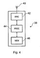
- Figure 4 gives an overview of a mobile telephone that is suitable for implementing an interference characterisation and removal scheme of the kind that has been described with reference to Figures 2 and 3 .
- Figure 4 shows a mobile telephone, generally indicated 38, comprising an antenna 40, a radio frequency chip (hereinafter FRIC) 42, a data processor 44 and a memory 46. Only the key components that are strictly necessary for understanding the invention have been shown in Figure 4 ; it will be apparent to the skilled person how a telephone of this type can be produced.
- FRIC radio frequency chip
- Signals are sent to and from the telephone 38 via the antenna 40.
- the antenna 40 exchanges singles with the FRIC 42.
- the FRIC 42 converts radio signals received at antenna 40 into base band signals for processing by processor 44 and provides the reverse conversion for signals travelling in the opposite direction.
- Many different types of processing are performed within processor 44 (often with the aid of memory 46), such as error protection coding, modulation and demodulation of data signals and calculation of signal to noise ratios, to name but a few.
- Software is loaded into the memory 46 that can be executed by the processor 44 to perform an interference characterisation and removal scheme of the kind described above with reference to Figures 2 and 3 .
Abstract
Description
- This invention can be used to reduce interference that hampers the performance of User Equipment (UE) receivers in CDMA systems that employ Orthogonal Variable Spreading Factor (OVSF) codes (see, for example, 3GPP TS 25.213, Spreading and modulation (FDD), Release 5). Interference is a major problem for CDMA systems, the capacity of the system is directly related to the level of interference in it. It is clear that by reducing the amount of interference in the CDMA system, it is possible to improve its performance.
- OVSF codes are designed so that in an ideal environment time synchronised signals that have been spread with OVSF codes do not interfere with each other. However, in practical (non-ideal) environments the orthogonality of these codes is never perfect because:
- 1. In frequency selective wideband channels the channel delay spread causes multiple delayed replicas of the same transmitted signal to arrive at the receiver. This is owing to obstacles in the environment giving rise to signal reflection and diffraction causing multipath propagation delay, which destroys orthogonality.
- 2. Even if the cell environment would not cause multipaths, in systems employing multiple transmit antennas these antennas typically introduce several multipath components with fractional chip delay offsets.
- Therefore also systems that employ OVSF codes suffer from intercode interference. In some systems, such as Multiple-Input Multiple-Output (MIMO) systems (see, for example, Huang H., Sandell M., Viswanathan H., "Achieving high data rates on the UMTS downlink shared channel using multiple antennas," 3G Mobile Communication Technologies Conference, London, March 2001, IEE Conference Publication No. 477, pp. 373-379). This interference can seriously harm the performance of the receiver.
- A well-known technique to reduce interference already employed in many systems is Joint Detection (JD), or Multi-User Detection (MUD) (see, for example, Verdu, S., Multiuser Detection, Cambridge University Press, Cambridge, UK, 1998). However, MUD is normally used in the base station to improve the estimation of uplink signals. MUD in CDMA requires the knowledge of the spreading codes, but this is no problem for the base station since the network itself has assigned these codes earlier, and thus it knows them.
- MUD techniques are typically not used in the UE receiver in the downlink because the UE does not have the knowledge of other users' spreading codes. In most systems the number of available spreading codes is so large that an exhaustive search using all of them is not possible in UE receivers which have limited power and processing capacities. For example in the 3GPP FDD system downlink it is possible to use
spreading factors -
US2002/154615 A1 discloses a detection method in which a CDMA-coded data signal is transmitted in the form of a data stream of spread data bursts between a transmitter and a receiver, hierarchical CDMA code being used for the transmissions. In a first step of the detection method, codes having a smaller spreading factor than a maximally to be detected spreading factor are detected. In a second step, codes having a larger spreading factor than in the previous step are detected, the detection results in the first step being taken into account. In a third step, the detection process is broken off if all codes are detected or otherwise the second step is repeated with the detection results last obtained in each instance until all codes are detected. - According to one aspect, the invention provides a method of evaluating the usage in a received signal of codes from a tree of codes that can be used to orthogonalise communications signals, the method comprising testing to determine if a given code is in use in the received signal and deducing from the result and from the tree structure the need to test in the received signal for the use of codes in the portion of the tree depending from said given code, characterised in that the method further comprises concluding that all codes in said portion are blocked from use if said given code is determined to be in use.
- In certain embodiments, the codes in the tree are OVSF codes.
- In certain embodiments, the code under test is tested by being correlated with the received signal in order to determine whether that code is used in the received signal.
- In certain embodiments, the tree structure permits the deduction of whether the codes in the portion of the tree depending from the code under test are blocked from use in the received signal.
- In certain embodiments, the tree structure permits the deduction of whether the codes in the portion of the tree depending from the code under test are unused. Such a deduction can be made with assistance from, for example, knowledge of the power levels associated with different layers of the tree.
- In certain embodiments, a tested code that is deemed to be used in the received signal is used to subtract from the received signal that part of the received signal that is attributable to that code. This can assist with, for example, interference cancellation in the case where the code under test is a potential interferer of another code that is known to be used in the received signal and that is desired to be demodulated.
- In certain embodiments, the method continues with the testing of other codes in the tree, to ascertain whether those codes are in use in the received signal. Of course, the testing of the further codes need not comprehend the testing of any subtrees for which testing has been deemed unnecessary and, moreover, the testing of the further codes can give rise to the identification, in the same manner as before, of further subtrees that do not require testing.
- The method described above can be performed by dedicated hardware (such as an ASIC) or by programmable or configurable hardware (such as a general purpose data processor or an FPGA). Of course, the invention also consists in software for causing data processing equipment to perform the methods described above.
- The present invention provides a method which has the potential to enable a UE receiver to efficiently identify interfering spreading codes using the knowledge of the underlying code structure, and to remove the interference these codes cause in the receiver. This method has the potential to significantly improve the performance of UE receivers in CDMA systems, and especially in MIMO systems where there is large amount of noise caused by orthogonal codes.
- By way of example, some embodiments of the invention will now be described by reference to the accompanying figures, in which:
-
Figure 1 illustrates an OVSF code tree; -
Figure 2 illustrates a walk-through path for tracking usage of codes in the tree ofFigure 1 ; -
Figure 3 illustrates a flow chart for a process of testing usage of codes in the tree ofFigure 1 ; and -
Figure 4 illustrates a mobile telephone in which an interference characterisation and removal scheme of the kind described with reference toFigures 2 and3 can be implemented. - OVSF spreading codes are arranged in a tree structure. This tree consists of nodes and each node details one spreading code. Each node has one parent, and two branches. These branches can also be seen as their own subtrees. The spreading codes in this tree structure are arranged in such a way that higher codes "mask" their own subtrees. For example (see
Figure 1 ), if code (8,2) is assigned to a user, it will not be possible to use codes (16,4) and (16,5) (or any code from their respective subtrees) simultaneously in the same cell, because those codes would not be orthogonal with code (8,2). Also, all parents of code (8,2) are blocked from use. In this document notation "code(m, n)" means a spreading code of spreading factor m (m = [1,2,4,8,16,32,64,128,256,512] in this embodiment), and n indicates the number of the spreading code of that spreading factor (0 ≤ n ≤ m). - The blocked codes are unusable because they are not orthogonal with the assigned code. This means that if any of those codes is used simultaneously with the assigned code, the resulting data streams will severely interfere with each other.
- If the receiver correlates the received signal with the correct spreading code, the result is the original signal. If the receiver correlates the received signal with a different (but still orthogonal) spreading code, the result is zero, assuming that the signal has not been distorted too much by interference. However, if the receiver correlates the received signal with a different code that is non-orthogonal with the correct code, then the result is non-zero, and the power level of the correlator output depends on how populated the subtree is with interfering codes.
- In CDMA systems the system power budget in the downlink is allocated in principle in a way which guarantees all bits an equal energy level over the interference flow, i.e.,
Eb /Io should be constant - This results in an arrangement where spreading factors and transmission powers are tightly combined. The spreading factor gives the relative transmit power in decibels, e.g., SF=128 will be sent using -21dB power level compared to a SF=1 code, because 10 log10 (128) = 21 dB. If a spreading factor is doubled, the required power level is correspondingly halved (i.e., reduced by 3 dB). Thus the receiver can easily conclude from the correlator power output level if the tested code is an interferer, or if the interferer is one of the tested code's descendents. This observation is exploited in the proposed interference cancellation scheme.
- The proposed scheme identifies the interfering codes by recursive walk-through of the code space. The idea is depicted in
Figure 2 . The found interfering codes are used to regenerate the interfering signals, and these are then subtracted from the composite signal resulting in a signal with much less interference. - A flow chart of the code testing and interference removal scheme is depicted in
Figure 3 . The spreading factor which starts the code search should be chosen to fit the system characteristics. For example in 3G-HSDPA systems SF=16 would be a good choice, because it is unlikely that a HSDPA system usually employs spreading factors lower than that. If it does employ such a code, it will not be a problem, because this method will then find all codes from the corresponding subtree. The algorithm is run until all subtrees are either blocked, known to be unused, or all leaf-nodes are tested. - According to the scheme shown in
Figure 3 , in a receiver for a CDMA system using OVSF codes for multiplexing, the unknown codes used on a link are identified at the receiver by a recursive walk-through of the code space. Possible spreading codes are tested in the correlator one-by-one. If the tested code is identified as an interferer, it is marked as a used code and its whole code sub-tree is marked as blocked. This walk-through the code space is started from a low-spreading factor and continued until all codes are tested, are found to be blocked, or are known to be unused. The number of codes the correlator has to check is manageable, because: - 1) Found interfering codes have their code subtrees blocked from further checking;
- 2) If the correlator output is close to zero, the code and its subtree are known to be unused, and thus need not be checked;
- 3) Low spreading-factor codes, which have many codes in their sub-trees, are tested first thus eliminating as many codes as possible early in the process.
- The flow chart of
Figure 3 will now be described in more detail. Instep 10, a starting value for SF is chosen. The value SF is the spreading factor and dictates the horizontal layer of the code tree at which the walk-through starts.Steps step 16, a decision is taken as to whether the process has reached the end of a layer of the code tree. If the end of such a layer is deemed to have been reached, the process moves to step 18 in which the process is moved down to the next layer of the code tree.Step 20 tests whether the final layer of the code tree has been processed.Steps 22 to 36 describe procedures that are performed during the testing of a node of the code tree and will now be discussed in greater detail. -
Step 22 tests whether the OVSF code of the node under test is already marked as a blocked code by virtue of a code higher up the tree being marked as a used code.Step 24 tests whether the OVSF code of the node under test has been specifically marked as unused during the testing of a node further up the code tree. Instep 26, the signal that is scheduled for interference reduction is correlated with the OVSF code of the node under test.Steps step 28, if the burst power of the correlation result is approximately nil, then the node and the nodes of any subtree depending from it are marked as unused OVSF codes. This deduction can be made because if the subtree of the node under test contained a used code it would not be orthogonal with the node under test and would therefore cause a non-zero correlation result. Instep 30, the burst power of the correlation result is compared with the burst power that is to be expected for a used spreading code in the current layer of the code tree. If the burst power of the correlation result is approximately the same as the burst power that would be expected of a used code at the current level of the code tree, then the spreading code at the node under test is deemed to be a used code and all codes in the subtree depending from the code under test are deemed to be blocked codes. Instep 36, the portion of the signal undergoing interference cancellation that is attributable to the spread spectrum signal using the OVSF code of the node under test is subtracted from the signal undergoing interference cancellation. - The proposed code search algorithm enables the use of multi-user detection techniques in the synchronous CDMA downlink. This is advantageous because it enables very efficient interference reduction in the UE receiver, and therefore improves its performance. The proposed interference characterisation and removal scheme is especially advantageous in high interference environments such as in MIMO systems, where it can increase the data throughput considerably.
- Of course, many modifications can be made to the details of the scheme shown in
Figure 3 . Some variants that offer reduced computational complexity without sacrificing too much performance will now be described. - In a first variant, the complexity is reduced by arranging that in each time frame, the code search algorithm first tries the spreading codes that were employed in the previous time frame, and after that performs a comprehensive search to only a small part of the code tree, such as one SF=8 subtree.
- In a second variant, the complexity is reduced by arranging that the code search algorithm ignores high SF spreading codes, such as 128, 256, and 512, because they will cause less interference than low SF spreading codes. Furthermore, the receiver can identify the codes from an SF under test as interfering codes if their correlator output results in a burst which has a power level that is higher than half of the power level of a burst from a genuine interfering code of that spreading factor.
- It may also be advantageous to keep in the active set such spreading codes as have been active in some of the previous frames, and not to remove them from the active set immediately when they are not used in the last frame tested, but only after a few frames of inactivity.
- It may also be advantageous in a new frame to try previously employed spreading codes with high spreading factors first, because those are easiest to find from a noisy signal.
- A further refinement to the proposed interference characterisation and removal scheme is to make it adaptive by applying it fully only when the perceived interference is very high, and conversely applying it only partly (perhaps using one of the variations noted above) or not at all when the perceived interference is low.
-
Figure 4 gives an overview of a mobile telephone that is suitable for implementing an interference characterisation and removal scheme of the kind that has been described with reference toFigures 2 and3 .Figure 4 shows a mobile telephone, generally indicated 38, comprising anantenna 40, a radio frequency chip (hereinafter FRIC) 42, adata processor 44 and amemory 46. Only the key components that are strictly necessary for understanding the invention have been shown inFigure 4 ; it will be apparent to the skilled person how a telephone of this type can be produced. - Signals are sent to and from the
telephone 38 via theantenna 40. Theantenna 40 exchanges singles with theFRIC 42. TheFRIC 42 converts radio signals received atantenna 40 into base band signals for processing byprocessor 44 and provides the reverse conversion for signals travelling in the opposite direction. Many different types of processing are performed within processor 44 (often with the aid of memory 46), such as error protection coding, modulation and demodulation of data signals and calculation of signal to noise ratios, to name but a few. Software is loaded into thememory 46 that can be executed by theprocessor 44 to perform an interference characterisation and removal scheme of the kind described above with reference toFigures 2 and3 .
Claims (11)
- A method of evaluating the usage in a received signal of codes from a tree of codes that can be used to orthogonalise communications signals, the method comprising testing to determine if a given code is in use in the received signal and deducing from the result and from the tree structure the need to test in the received signal for the use of codes in the portion of the tree depending from said given code, characterised in that the method further comprises concluding that all codes in said portion are blocked from use if said given code is determined to be in use.
- A method according to claim 1, further comprising utilising, where said given code is deemed unused, a value indicative of the signal power associated with that code to make predictions about the usage of codes in said portion.
- A method according to any one of the preceding claims, wherein the step of testing the usage of a given code comprises correlating that code with the received signal.
- A method of processing a received signal, comprising using the method of any one of the preceding claims to determine that a given code from said tree is in use in said signal and removing from said signal that part of the signal that is attributable to said given code.
- A method according to any one of the preceding claims, wherein said tree is an OVSF code tree.
- Apparatus (38) for evaluating the usage in a received signal of codes from a tree of codes that can be used to orthogonalise communications signals, the apparatus (30) comprising means (44) for testing to determine if a given code is in use in the received signal and means for deducing from the result and from the tree structure the need to test in the received signal for the use of codes in the portion of the tree depending from said given code, characterised in that the
deducing means (44) is arranged to conclude that all codes in said portion are blocked from use if said given code is determined to be in use. - Apparatus according to claim 6, wherein said deducing means is arranged to utilise, where said given code is deemed unused, a value indicative of the signal power associated with that code to make predictions about the usage of codes in said portion.
- Apparatus according to claim 6 to 7, wherein the testing means is arranged to test the usage of a given code by correlating that code with the received signal.
- Apparatus according to any one of claims 6 to 8, wherein said tree is an OVSF code tree.
- A system for processing a received signal, comprising apparatus according to any one of claims 6 to 9 for determining that a given code from said tree is in use in said signal and means for removing from said signal that part of the signal that is attributable to said given code.
- A program for causing data processing apparatus to perform a method according to any one of claims 1 to 5.
Applications Claiming Priority (2)
| Application Number | Priority Date | Filing Date | Title |
|---|---|---|---|
| GBGB0426548.4A GB0426548D0 (en) | 2004-12-02 | 2004-12-02 | Interference characterisation and removal |
| PCT/GB2005/004576 WO2006059088A1 (en) | 2004-12-02 | 2005-11-30 | Interference characterisation and removal |
Publications (2)
| Publication Number | Publication Date |
|---|---|
| EP1817856A1 EP1817856A1 (en) | 2007-08-15 |
| EP1817856B1 true EP1817856B1 (en) | 2010-10-27 |
Family
ID=34043997
Family Applications (1)
| Application Number | Title | Priority Date | Filing Date |
|---|---|---|---|
| EP05810705A Not-in-force EP1817856B1 (en) | 2004-12-02 | 2005-11-30 | Interference characterisation and removal |
Country Status (9)
| Country | Link |
|---|---|
| US (1) | US8295415B2 (en) |
| EP (1) | EP1817856B1 (en) |
| KR (1) | KR101037122B1 (en) |
| CN (1) | CN101069376B (en) |
| AT (1) | ATE486419T1 (en) |
| DE (1) | DE602005024434D1 (en) |
| GB (1) | GB0426548D0 (en) |
| TW (1) | TWI343198B (en) |
| WO (1) | WO2006059088A1 (en) |
Families Citing this family (5)
| Publication number | Priority date | Publication date | Assignee | Title |
|---|---|---|---|---|
| WO2007066283A1 (en) * | 2005-12-06 | 2007-06-14 | Nxp B.V. | Determination of active spreading codes and their powers |
| US7916841B2 (en) * | 2006-09-29 | 2011-03-29 | Mediatek Inc. | Method and apparatus for joint detection |
| WO2009019540A1 (en) * | 2007-08-09 | 2009-02-12 | Freescale Semiconductor, Inc. | Method and decoder for decoding a wireless transmission from a predefined user |
| WO2012099519A2 (en) * | 2011-01-17 | 2012-07-26 | Telefonaktiebolaget L M Ericsson (Publ) | Code allocation for uplink mimo |
| US9319111B2 (en) | 2011-01-17 | 2016-04-19 | Optis Wireless Technology, Llc | Code allocation for uplink MIMO |
Family Cites Families (17)
| Publication number | Priority date | Publication date | Assignee | Title |
|---|---|---|---|---|
| US5852630A (en) * | 1997-07-17 | 1998-12-22 | Globespan Semiconductor, Inc. | Method and apparatus for a RADSL transceiver warm start activation procedure with precoding |
| US6154443A (en) | 1998-08-11 | 2000-11-28 | Industrial Technology Research Institute | FFT-based CDMA RAKE receiver system and method |
| US6426983B1 (en) | 1998-09-14 | 2002-07-30 | Terayon Communication Systems, Inc. | Method and apparatus of using a bank of filters for excision of narrow band interference signal from CDMA signal |
| WO2000019732A2 (en) | 1998-09-29 | 2000-04-06 | Samsung Electronics Co., Ltd. | Device and method for generating spreading code and spreading channel signals using spreading code in cdma communication system |
| EP0993127A1 (en) | 1998-10-06 | 2000-04-12 | Texas Instruments Incorporated | Method and apparatus using Walsh-Hadamard transformation for forward link multiuser detection in CDMA systems |
| GB2351422A (en) | 1999-06-25 | 2000-12-27 | Roke Manor Research | Association of a training code to a channelisation code in a mobile telecommunications system |
| JP2001086034A (en) * | 1999-09-14 | 2001-03-30 | Nec Corp | Metthod and circuit for detecting spreading code in perch channel detection circuit |
| DE10003734A1 (en) * | 2000-01-28 | 2001-08-02 | Bosch Gmbh Robert | Detection method and device |
| JP4574805B2 (en) | 2000-06-30 | 2010-11-04 | テレフオンアクチーボラゲット エル エム エリクソン(パブル) | Communication system and power control method thereof |
| FI20010937A0 (en) * | 2001-05-04 | 2001-05-04 | Nokia Corp | Selection of a spreading code in a spread spectrum system |
| JP2003087219A (en) | 2001-09-07 | 2003-03-20 | Mitsubishi Cable Ind Ltd | Device and method for removing interference |
| US6552996B2 (en) * | 2001-09-18 | 2003-04-22 | Interdigital Communications Corporation | OVSF code system and methods |
| CN100566321C (en) | 2002-07-18 | 2009-12-02 | 美商内数位科技公司 | Orthogonal variable frequency extension factor code is assigned |
| US7224721B2 (en) * | 2002-10-11 | 2007-05-29 | The Mitre Corporation | System for direct acquisition of received signals |
| TW595144B (en) | 2003-02-21 | 2004-06-21 | Accton Technology Corp | Power control method for CDMA communication system |
| US7822150B2 (en) | 2003-03-15 | 2010-10-26 | Alcatel-Lucent Usa Inc. | Spherical decoder for wireless communications |
| US7174356B2 (en) | 2003-06-24 | 2007-02-06 | Motorola, Inc. | Complex multiplication method and apparatus with phase rotation |
-
2004
- 2004-12-02 GB GBGB0426548.4A patent/GB0426548D0/en not_active Ceased
-
2005
- 2005-11-30 US US11/792,233 patent/US8295415B2/en not_active Expired - Fee Related
- 2005-11-30 CN CN2005800415507A patent/CN101069376B/en not_active Expired - Fee Related
- 2005-11-30 AT AT05810705T patent/ATE486419T1/en not_active IP Right Cessation
- 2005-11-30 WO PCT/GB2005/004576 patent/WO2006059088A1/en active Application Filing
- 2005-11-30 EP EP05810705A patent/EP1817856B1/en not_active Not-in-force
- 2005-11-30 DE DE602005024434T patent/DE602005024434D1/en active Active
- 2005-11-30 KR KR1020077015072A patent/KR101037122B1/en not_active IP Right Cessation
- 2005-12-01 TW TW094142307A patent/TWI343198B/en not_active IP Right Cessation
Also Published As
| Publication number | Publication date |
|---|---|
| TWI343198B (en) | 2011-06-01 |
| KR101037122B1 (en) | 2011-05-26 |
| WO2006059088A1 (en) | 2006-06-08 |
| EP1817856A1 (en) | 2007-08-15 |
| CN101069376A (en) | 2007-11-07 |
| GB0426548D0 (en) | 2005-01-05 |
| ATE486419T1 (en) | 2010-11-15 |
| TW200631345A (en) | 2006-09-01 |
| CN101069376B (en) | 2011-10-05 |
| DE602005024434D1 (en) | 2010-12-09 |
| US20090129445A1 (en) | 2009-05-21 |
| US8295415B2 (en) | 2012-10-23 |
| KR20070089729A (en) | 2007-08-31 |
Similar Documents
| Publication | Publication Date | Title |
|---|---|---|
| KR100343088B1 (en) | Method and apparatus for joint detection of data in a direct sequence spread spectrum communications system | |
| CA2369499C (en) | Multichannel cdma subtractive interference canceler | |
| EP1147620B1 (en) | Apparatus and methods for interference cancellation in spread spectrum communication systems | |
| US7729411B2 (en) | Joint detector in a code division multiple access radio receiver | |
| US20100238981A1 (en) | Interference cancellation in variable codelength systems for multi-acess communication | |
| US7133435B2 (en) | Interference cancellation system and method | |
| EP1569355A2 (en) | Interference cancellation in a CDMA receiver | |
| US20030189972A1 (en) | Method and device for interference cancellation in a CDMA wireless communication system | |
| US20080304554A1 (en) | Method and apparatus for estimating impairment covariance matrices using unoccupied spreading codes | |
| KR20050005565A (en) | Multi-user detection using an adaptive combination of joint detection and successive interference cancellation | |
| US6904081B2 (en) | Spread spectrum receiver apparatus and method | |
| JP5412657B2 (en) | Receiver with chip level equalization | |
| EP1817856B1 (en) | Interference characterisation and removal | |
| US6078573A (en) | Circuitry and method for demodulating code division multiple access (CDMA) signals | |
| Kawabe et al. | Advanced CDMA scheme based on interference cancellation | |
| TWI232645B (en) | Segment-wise channel equalization based data estimation | |
| WO2002003561A1 (en) | Receiver and method of receiving a cdma signal in presence of interferers with unknown spreading factors | |
| JP4815556B2 (en) | Determination of active spreading codes and their power | |
| US7450671B2 (en) | Interference cancellation method in radio system | |
| AU7920698A (en) | Reception method and receiver | |
| JP2002152176A (en) | Method and device for reducing interference of cdma receiver | |
| JP2006520128A (en) | Multi-user detection for signals with different data rates | |
| Madkour et al. | A novel downlink blind interference cancellation in a W-CDMA mobile communications system | |
| EP0973283B1 (en) | Probing apparatus and method for a spread-spectrum communications system |
Legal Events
| Date | Code | Title | Description |
|---|---|---|---|
| PUAI | Public reference made under article 153(3) epc to a published international application that has entered the european phase |
Free format text: ORIGINAL CODE: 0009012 |
|
| 17P | Request for examination filed |
Effective date: 20070608 |
|
| AK | Designated contracting states |
Kind code of ref document: A1 Designated state(s): AT BE BG CH CY CZ DE DK EE ES FI FR GB GR HU IE IS IT LI LT LU LV MC NL PL PT RO SE SI SK TR |
|
| DAX | Request for extension of the european patent (deleted) | ||
| 17Q | First examination report despatched |
Effective date: 20081104 |
|
| RAP1 | Party data changed (applicant data changed or rights of an application transferred) |
Owner name: MSTAR FRANCE SAS Owner name: MSTAR SEMICONDUCTOR, INC Owner name: MSTAR SOFTWARE R&D (SHENZHEN) LTD |
|
| RAP1 | Party data changed (applicant data changed or rights of an application transferred) |
Owner name: MSTAR SOFTWARE R&D (SHENZHEN) LTD Owner name: MSTAR SEMICONDUCTOR, INC Owner name: MSTAR FRANCE SAS |
|
| GRAP | Despatch of communication of intention to grant a patent |
Free format text: ORIGINAL CODE: EPIDOSNIGR1 |
|
| GRAS | Grant fee paid |
Free format text: ORIGINAL CODE: EPIDOSNIGR3 |
|
| GRAA | (expected) grant |
Free format text: ORIGINAL CODE: 0009210 |
|
| AK | Designated contracting states |
Kind code of ref document: B1 Designated state(s): AT BE BG CH CY CZ DE DK EE ES FI FR GB GR HU IE IS IT LI LT LU LV MC NL PL PT RO SE SI SK TR |
|
| REG | Reference to a national code |
Ref country code: GB Ref legal event code: FG4D |
|
| REG | Reference to a national code |
Ref country code: CH Ref legal event code: EP |
|
| REG | Reference to a national code |
Ref country code: IE Ref legal event code: FG4D |
|
| REF | Corresponds to: |
Ref document number: 602005024434 Country of ref document: DE Date of ref document: 20101209 Kind code of ref document: P |
|
| REG | Reference to a national code |
Ref country code: NL Ref legal event code: VDEP Effective date: 20101027 |
|
| LTIE | Lt: invalidation of european patent or patent extension |
Effective date: 20101027 |
|
| PG25 | Lapsed in a contracting state [announced via postgrant information from national office to epo] |
Ref country code: LT Free format text: LAPSE BECAUSE OF FAILURE TO SUBMIT A TRANSLATION OF THE DESCRIPTION OR TO PAY THE FEE WITHIN THE PRESCRIBED TIME-LIMIT Effective date: 20101027 |
|
| PG25 | Lapsed in a contracting state [announced via postgrant information from national office to epo] |
Ref country code: NL Free format text: LAPSE BECAUSE OF FAILURE TO SUBMIT A TRANSLATION OF THE DESCRIPTION OR TO PAY THE FEE WITHIN THE PRESCRIBED TIME-LIMIT Effective date: 20101027 Ref country code: PT Free format text: LAPSE BECAUSE OF FAILURE TO SUBMIT A TRANSLATION OF THE DESCRIPTION OR TO PAY THE FEE WITHIN THE PRESCRIBED TIME-LIMIT Effective date: 20110228 Ref country code: LV Free format text: LAPSE BECAUSE OF FAILURE TO SUBMIT A TRANSLATION OF THE DESCRIPTION OR TO PAY THE FEE WITHIN THE PRESCRIBED TIME-LIMIT Effective date: 20101027 Ref country code: SE Free format text: LAPSE BECAUSE OF FAILURE TO SUBMIT A TRANSLATION OF THE DESCRIPTION OR TO PAY THE FEE WITHIN THE PRESCRIBED TIME-LIMIT Effective date: 20101027 Ref country code: BG Free format text: LAPSE BECAUSE OF FAILURE TO SUBMIT A TRANSLATION OF THE DESCRIPTION OR TO PAY THE FEE WITHIN THE PRESCRIBED TIME-LIMIT Effective date: 20110127 Ref country code: FI Free format text: LAPSE BECAUSE OF FAILURE TO SUBMIT A TRANSLATION OF THE DESCRIPTION OR TO PAY THE FEE WITHIN THE PRESCRIBED TIME-LIMIT Effective date: 20101027 Ref country code: IS Free format text: LAPSE BECAUSE OF FAILURE TO SUBMIT A TRANSLATION OF THE DESCRIPTION OR TO PAY THE FEE WITHIN THE PRESCRIBED TIME-LIMIT Effective date: 20110227 Ref country code: SI Free format text: LAPSE BECAUSE OF FAILURE TO SUBMIT A TRANSLATION OF THE DESCRIPTION OR TO PAY THE FEE WITHIN THE PRESCRIBED TIME-LIMIT Effective date: 20101027 Ref country code: AT Free format text: LAPSE BECAUSE OF FAILURE TO SUBMIT A TRANSLATION OF THE DESCRIPTION OR TO PAY THE FEE WITHIN THE PRESCRIBED TIME-LIMIT Effective date: 20101027 |
|
| PG25 | Lapsed in a contracting state [announced via postgrant information from national office to epo] |
Ref country code: BE Free format text: LAPSE BECAUSE OF FAILURE TO SUBMIT A TRANSLATION OF THE DESCRIPTION OR TO PAY THE FEE WITHIN THE PRESCRIBED TIME-LIMIT Effective date: 20101027 Ref country code: GR Free format text: LAPSE BECAUSE OF FAILURE TO SUBMIT A TRANSLATION OF THE DESCRIPTION OR TO PAY THE FEE WITHIN THE PRESCRIBED TIME-LIMIT Effective date: 20110128 Ref country code: MC Free format text: LAPSE BECAUSE OF NON-PAYMENT OF DUE FEES Effective date: 20101130 |
|
| REG | Reference to a national code |
Ref country code: CH Ref legal event code: PL |
|
| PG25 | Lapsed in a contracting state [announced via postgrant information from national office to epo] |
Ref country code: LI Free format text: LAPSE BECAUSE OF NON-PAYMENT OF DUE FEES Effective date: 20101130 Ref country code: EE Free format text: LAPSE BECAUSE OF FAILURE TO SUBMIT A TRANSLATION OF THE DESCRIPTION OR TO PAY THE FEE WITHIN THE PRESCRIBED TIME-LIMIT Effective date: 20101027 Ref country code: CZ Free format text: LAPSE BECAUSE OF FAILURE TO SUBMIT A TRANSLATION OF THE DESCRIPTION OR TO PAY THE FEE WITHIN THE PRESCRIBED TIME-LIMIT Effective date: 20101027 Ref country code: CH Free format text: LAPSE BECAUSE OF NON-PAYMENT OF DUE FEES Effective date: 20101130 Ref country code: ES Free format text: LAPSE BECAUSE OF FAILURE TO SUBMIT A TRANSLATION OF THE DESCRIPTION OR TO PAY THE FEE WITHIN THE PRESCRIBED TIME-LIMIT Effective date: 20110207 |
|
| PG25 | Lapsed in a contracting state [announced via postgrant information from national office to epo] |
Ref country code: DK Free format text: LAPSE BECAUSE OF FAILURE TO SUBMIT A TRANSLATION OF THE DESCRIPTION OR TO PAY THE FEE WITHIN THE PRESCRIBED TIME-LIMIT Effective date: 20101027 Ref country code: PL Free format text: LAPSE BECAUSE OF FAILURE TO SUBMIT A TRANSLATION OF THE DESCRIPTION OR TO PAY THE FEE WITHIN THE PRESCRIBED TIME-LIMIT Effective date: 20101027 Ref country code: RO Free format text: LAPSE BECAUSE OF FAILURE TO SUBMIT A TRANSLATION OF THE DESCRIPTION OR TO PAY THE FEE WITHIN THE PRESCRIBED TIME-LIMIT Effective date: 20101027 Ref country code: SK Free format text: LAPSE BECAUSE OF FAILURE TO SUBMIT A TRANSLATION OF THE DESCRIPTION OR TO PAY THE FEE WITHIN THE PRESCRIBED TIME-LIMIT Effective date: 20101027 |
|
| PLBE | No opposition filed within time limit |
Free format text: ORIGINAL CODE: 0009261 |
|
| STAA | Information on the status of an ep patent application or granted ep patent |
Free format text: STATUS: NO OPPOSITION FILED WITHIN TIME LIMIT |
|
| 26N | No opposition filed |
Effective date: 20110728 |
|
| PG25 | Lapsed in a contracting state [announced via postgrant information from national office to epo] |
Ref country code: IE Free format text: LAPSE BECAUSE OF NON-PAYMENT OF DUE FEES Effective date: 20101130 |
|
| REG | Reference to a national code |
Ref country code: DE Ref legal event code: R097 Ref document number: 602005024434 Country of ref document: DE Effective date: 20110728 |
|
| PG25 | Lapsed in a contracting state [announced via postgrant information from national office to epo] |
Ref country code: CY Free format text: LAPSE BECAUSE OF FAILURE TO SUBMIT A TRANSLATION OF THE DESCRIPTION OR TO PAY THE FEE WITHIN THE PRESCRIBED TIME-LIMIT Effective date: 20101027 |
|
| PG25 | Lapsed in a contracting state [announced via postgrant information from national office to epo] |
Ref country code: LU Free format text: LAPSE BECAUSE OF NON-PAYMENT OF DUE FEES Effective date: 20101130 Ref country code: HU Free format text: LAPSE BECAUSE OF FAILURE TO SUBMIT A TRANSLATION OF THE DESCRIPTION OR TO PAY THE FEE WITHIN THE PRESCRIBED TIME-LIMIT Effective date: 20110428 |
|
| PG25 | Lapsed in a contracting state [announced via postgrant information from national office to epo] |
Ref country code: TR Free format text: LAPSE BECAUSE OF FAILURE TO SUBMIT A TRANSLATION OF THE DESCRIPTION OR TO PAY THE FEE WITHIN THE PRESCRIBED TIME-LIMIT Effective date: 20101027 |
|
| REG | Reference to a national code |
Ref country code: FR Ref legal event code: PLFP Year of fee payment: 11 |
|
| REG | Reference to a national code |
Ref country code: FR Ref legal event code: PLFP Year of fee payment: 12 |
|
| REG | Reference to a national code |
Ref country code: FR Ref legal event code: PLFP Year of fee payment: 13 |
|
| REG | Reference to a national code |
Ref country code: FR Ref legal event code: PLFP Year of fee payment: 14 |
|
| PGFP | Annual fee paid to national office [announced via postgrant information from national office to epo] |
Ref country code: DE Payment date: 20181015 Year of fee payment: 14 |
|
| PGFP | Annual fee paid to national office [announced via postgrant information from national office to epo] |
Ref country code: GB Payment date: 20181025 Year of fee payment: 14 Ref country code: IT Payment date: 20181119 Year of fee payment: 14 Ref country code: FR Payment date: 20181017 Year of fee payment: 14 |
|
| REG | Reference to a national code |
Ref country code: DE Ref legal event code: R119 Ref document number: 602005024434 Country of ref document: DE |
|
| GBPC | Gb: european patent ceased through non-payment of renewal fee |
Effective date: 20191130 |
|
| PG25 | Lapsed in a contracting state [announced via postgrant information from national office to epo] |
Ref country code: IT Free format text: LAPSE BECAUSE OF NON-PAYMENT OF DUE FEES Effective date: 20191130 Ref country code: FR Free format text: LAPSE BECAUSE OF NON-PAYMENT OF DUE FEES Effective date: 20191130 Ref country code: GB Free format text: LAPSE BECAUSE OF NON-PAYMENT OF DUE FEES Effective date: 20191130 Ref country code: DE Free format text: LAPSE BECAUSE OF NON-PAYMENT OF DUE FEES Effective date: 20200603 |