EP1817085B1 - Residential fire sprinkler - Google Patents
Residential fire sprinkler Download PDFInfo
- Publication number
- EP1817085B1 EP1817085B1 EP05852223A EP05852223A EP1817085B1 EP 1817085 B1 EP1817085 B1 EP 1817085B1 EP 05852223 A EP05852223 A EP 05852223A EP 05852223 A EP05852223 A EP 05852223A EP 1817085 B1 EP1817085 B1 EP 1817085B1
- Authority
- EP
- European Patent Office
- Prior art keywords
- sprinkler
- longitudinal axis
- feet
- residential fire
- residential
- Prior art date
- Legal status (The legal status is an assumption and is not a legal conclusion. Google has not performed a legal analysis and makes no representation as to the accuracy of the status listed.)
- Expired - Lifetime
Links
Images


Classifications
-
- A—HUMAN NECESSITIES
- A62—LIFE-SAVING; FIRE-FIGHTING
- A62C—FIRE-FIGHTING
- A62C37/00—Control of fire-fighting equipment
- A62C37/08—Control of fire-fighting equipment comprising an outlet device containing a sensor, or itself being the sensor, i.e. self-contained sprinklers
- A62C37/10—Releasing means, e.g. electrically released
- A62C37/11—Releasing means, e.g. electrically released heat-sensitive
- A62C37/14—Releasing means, e.g. electrically released heat-sensitive with frangible vessels
-
- A—HUMAN NECESSITIES
- A62—LIFE-SAVING; FIRE-FIGHTING
- A62C—FIRE-FIGHTING
- A62C31/00—Delivery of fire-extinguishing material
- A62C31/02—Nozzles specially adapted for fire-extinguishing
-
- B—PERFORMING OPERATIONS; TRANSPORTING
- B05—SPRAYING OR ATOMISING IN GENERAL; APPLYING FLUENT MATERIALS TO SURFACES, IN GENERAL
- B05B—SPRAYING APPARATUS; ATOMISING APPARATUS; NOZZLES
- B05B1/00—Nozzles, spray heads or other outlets, with or without auxiliary devices such as valves, heating means
- B05B1/26—Nozzles, spray heads or other outlets, with or without auxiliary devices such as valves, heating means with means for mechanically breaking-up or deflecting the jet after discharge, e.g. with fixed deflectors; Breaking-up the discharged liquid or other fluent material by impinging jets
- B05B1/262—Nozzles, spray heads or other outlets, with or without auxiliary devices such as valves, heating means with means for mechanically breaking-up or deflecting the jet after discharge, e.g. with fixed deflectors; Breaking-up the discharged liquid or other fluent material by impinging jets with fixed deflectors
- B05B1/265—Nozzles, spray heads or other outlets, with or without auxiliary devices such as valves, heating means with means for mechanically breaking-up or deflecting the jet after discharge, e.g. with fixed deflectors; Breaking-up the discharged liquid or other fluent material by impinging jets with fixed deflectors the liquid or other fluent material being symmetrically deflected about the axis of the nozzle
Definitions
- An automatic sprinkler system is one of the most widely used devices for fire protection. These systems have sprinklers that are activated once the ambient temperature in an environment, such as a room or a building, exceeds a predetermined value. Once activated, the sprinklers distribute fire-extinguishing fluid, preferably water, in the room or building.
- a sprinkler system depending on its specified configuration is considered effective if it controls or suppresses a fire. Failures of such systems may occur when the system has been rendered inoperative during building alteration or disuse, or the occupancy hazard has been increased beyond initial system capability.
- the sprinkler system can be provided with a suitable fire fighting fluid or a water supply (e.g., a reservoir or from a municipal water supply). Such supply may be separate from that used by a fire department. Regardless of the type of supply, the sprinkler system is provided with a main that enters the building to supply a riser. Connected at the riser are valves, meters, and, preferably, an alarm to sound when water flow within the system is above or below a predetermined minimum value. At the top of a vertical riser, a horizontally disposed array of pipes extends throughout the fire compartment in the building. Other risers may feed distribution networks to systems in adjacent fire compartments. Compartmentalization can divide a large building horizontally, on a single floor, and vertically, floor to floor. Thus, several sprinkler systems may serve one building.
- a suitable fire fighting fluid or a water supply e.g., a reservoir or from a municipal water supply.
- a water supply e.g., a reservoir or from a municipal water supply
- branch lines carry the sprinklers.
- a sprinkler may extend up from a branch line, placing the sprinkler relatively close to the ceiling, or a sprinkler can be pendent below the branch line.
- a flush-mounted pendant sprinkler may extend only slightly below the ceiling.
- NFPA 13 National Fire Protection Association
- Standards 13D and 13R various design consideration and installation parameters for a fire protection system.
- NFPA 13, 13D, and 13R recognize the use of residential sprinklers by requiring that such sprinkler in a residential fire protection system to be installed based on certain criteria for residential occupancies, which can include commercial dwelling units (e.g., rental apartments, lodging and rooming houses, board and care facilities, hospitals, motels or hotels).
- UL 1626 (Oct 2003) requires a sprinkler, as described in Table 6.1 of Section 6, to deliver a minimum flow rate (liters per minute (gallons per minute or "GPM")) for a specified coverage area (square meter (square feet or "ft 2 ”)) to provide for a desired average density of 2,04 liters per minute/m 2 (0.05 GPM/ft 2 ).
- GPM Underwriters Laboratory Incorporated
- the minimum flow rate tabulated in Table 6.1 can be used to calculate a predicted minimum fluid pressure needed to operate a sprinkler by virtue of a rated K-factor of the sprinkler.
- the actual minimum pressure of the sprinkler may not be the same as the predicted minimum pressure, which can be calculated using the given minimum flow rate of Table 6.1 in UL 1626 and the rated K-factor of the sprinkler. Further, the actual minimum fluid flow rate to pass these distribution tests of UL 1626 for a specified coverage area may even be higher than the tabulated minimum flow rate given in Table 6.1 of UL 1626. Consequently, any attempt to provide for a listed sprinkler (i.e., an operational sprinkler suitable for the protection of a dwelling unit) cannot be predicted by applications of a known formula to known residential sprinklers.
- a known 70,7 K-factor (4.9 K-factor in US-units) residential sprinkler can provide the required minimum flow rates of 75,8 liters per minute (20 GPM) to pass the distribution tests for a 1,86 m 2 (20 feet by 20 feet) coverage area whereas another commercially available 70,7 K-factor (4.9 K-factor) residential sprinkler by another manufacturer cannot.
- Another 70,7 K-factor (4.9 K-factor) residential sprinkler has satisfied the UL 1626 testing requirements for a 18 feet by 18 feet coverage area with the actual flow rates for these UL 1626 tests being the same as the required minimum flow rates in Table 6.1 of UL 1626 and at a pressure predicted by the 70,7 K-factor (4.9 K-factor) value.
- these examples show that there is a great amount of uncertainty in any potential sprinkler design that cannot be determined unless the sprinkler is built and tested in accordance with a testing or listing authority.
- the present invention provides a residential fire sprinkler that delivers fluid flow at a substantially lower minimum design pressure compared to existing residential pendent fire sprinklers while meeting performance tests for certain coverage areas.
- This ability of the sprinkler to meet testing requirements of UL 1626 allows the sprinkler to be listed so that the sprinkler qualifies as a residential sprinkler for installation in accordance with the 2002 Edition of NFPA 13, 13, and 13R (2002).
- the residential fire sprinkler embodying a preferred embodiment of the present invention was able to meet the performance tests of UL 1626 at 30 percent lower operating pressure than a known residential fire sprinklers for design protection areas of 1,67 m 2 (18 feet by 18 feet) or greater.
- the sprinkler has a minimum pressure at which it is designed to operate at a specified coverage area in residential applications, which minimum pressure is lower than those of known sprinklers. And because the sprinkler has various minimum operating pressures that are lower than known residential sprinklers for respective specified coverage areas, the sprinkler provides an advantageous feature that advances the state of the fire protection art.
- a pendent type residential fire sprinkler as defined in claim 1 is provided.
- FIGs 1-3 illustrate the preferred embodiments of a pendent type residential fire sprinkler 100 with a K-factor of at least 86,6 (6 in US-units) that can be used in residential applications.
- a preferred embodiment of the residential sprinkler 100 is shown mounted to a fire protection piping 10 that extends along axis B-B.
- the residential sprinkler 100 is preferably a pendent sprinkler configuration oriented generally along axis A-A, which is generally orthogonal over an area to be protected.
- the area to be protected can be generally a floor area of a compartment in the residential dwelling unit.
- the term "residential” is a "dwelling unit" as defined in NFPA Standard 13D, 13R (2002), which can include commercial dwelling units ⁇ e.g., rental apartments, lodging and rooming houses, board and care facilities, hospitals, motels or hotels) to indicate one or more rooms, arranged for the use of individuals living together, as in a single housekeeping unit, that normally have cooking, living, sanitary, and sleeping facilities.
- the residential dwelling unit normally includes a plurality of compartments as defined in the 2002 Edition of NFPA 13, 13, and 13R (2002), where generally each compartment is a space that is enclosed by walls and ceiling.
- the discharge coefficient or K-factor relates in part to the shape of the passageway 26 and other dimensions of the passageway 26 of the sprinkler 100.
- the pendent residential sprinkler 100 includes a body 12 with frame arms 14 extending from a portion of the body 12.
- the frame arms 14 can be unitary with a boss 34 that retains an annular structure 16 so that both the frame arms 14 and the annular structure 16 provide a fluid deflecting assembly 18.
- the annular structure 16 is preferably in the form of a plate 20.
- the plate 20 can Include a generally concave or dished portion 22 about the longitudinal axis A-A.
- the plate 20 is also provided with a plurality of tines 24A oriented about the longitudinal axis A-A.
- Two close-ended slots 40 are located at about 90 degrees with respect to the frame arms 14.
- Two nubs 42 and two through-openings 44 are also located 90 degrees with respect to the frame arms 14.
- the body 12 has an outer surface provided with a threaded portion 12A and multiple-flat portion 12B connected by a transition portion 12C.
- the threaded portion 12A can preferably include threads greater than 12,7 mm (1 ⁇ 2 inch) National-Pipe-Thread ("NPT") and preferably 19,05 mm (3 ⁇ 4 inch) NPT threads.
- the flat portion 12B can include a four-sided flat for engagement with an installation tool.
- the body 12 is provided with a passageway 26 that extends from an inlet 26A to an outlet 26B along the longitudinal axis A-A over a length of less than 25,4 mm (one inch).
- the inlet 26A includes a generally planar entrance surface disposed about the longitudinal axis A-A.
- the outlet 26B includes a generally planar exit surface disposed about the longitudinal axis A-A.
- the inlet 26A includes a compound curved portion 26C defined by a radiused surface rotated about the longitudinal axis A-A to define a generally bellmouth shaped surface.
- the compound curved portion 26C is contiguous to a first end of tapered linear surface 26D disposed about the longitudinal axis A-A to define a conic passageway portion 26D of a first length LP1 along the longitudinal axis A-A with a first taper angle a with respect to the longitudinal axis A-A.
- the first end 26D1 of the conic passageway portion 26D has a first diameter D1.
- the conic passageway portion 26D is contiguous to a cylindrical passageway portion 26E at a second end 26D2 of the conic passageway 26.
- the second end 26D2 of the conic passageway 26 and the cylindrical passageway portion 26E have a second diameter D2 of preferably about 86 percent of the first diameter D1.
- the cylindrical passageway 26 is contiguous to a flared generally planar surface portion 26F, which is contiguous to a passageway chamfered portion 26G.
- the flared generally planar portion has a third diameter D3 of preferably about 110 percent of the second diameter D2.
- the passageway chamfered portion 26G has a taper disposed about the longitudinal axis A-A to define a conic cylinder.
- the taper of the passageway chamfered portion 26G has a second taper angle ⁇ with respect to the longitudinal axis A-A.
- the bellmouth portion includes a radius of curvature of less than about 2,5 mm (0.1 inches); the first length LP1 of the conic passageway 26 is about 20,2 mm (0.8 inch); first diameter D1 is about 15,2 mm (0.6 inch); second diameter D2 is about 12,7 mm (0.5 inch); third diameter D3 is about 15,2 mm (0.6 inch); convergent first angle ⁇ of about 4 degrees with respect to the longitudinal axis A-A, the divergent second angle ⁇ of about 45 degrees with respect to the longitudinal axis A-A, and a suitable surface finish of the passageway 26 of preferably less than 2,5 mm (100 micro inch). It is believed that at least these features provide for the achievement of a rated discharge coefficient or rated K-factor of at least 86,6 (6 in US-units) and more preferably, about 99,6 (6.9 in US-units).
- the outlet 26B of the sprinkler 100 can be provided with a plug 28 coupled to a washer 30 so that the perimeter of the washer 30 is contiguous to the flared planar surface.
- the plug 28 can be provided with a groove 28A so that an ejection spring 32 can be mounted in the groove 28A and two free ends of the ejection spring 32 are coupled to the respective frame arms 14 on one of two boss projections of the frame arm ( Fig. 2 ).
- At least one frame arm 14 extends from the multiple-flat portion 12B proximate the outlet 26B.
- the at least one frame arm 14 has various cross-sections as the arm 14 extends away from the outlet.
- two frame arms 14 extend generally along the longitudinal axis and converge towards each other with a boss 34 disposed between the two frame arms 14.
- the boss 34 has a tip portion 34A facing the outlet 26B.
- the tip portion 34A is disposed at preferably about less than 25,4 mm (one inch) from the generally planar flared portion 26F of the passageway 26 and located at less than 76,2 mm (3 inches) from the inlet 26A end of the body 12.
- a stepped portion is provided between the tip portion 34A and the tail portion 34B of the boss 34 so that the annular plate 20 can be mounted thereon.
- the boss 34 includes a counterbore portion 34C and an internally threaded passageway 34D.
- the counterbore portion 34C preferably has a diameter of about 5,1 mm (0.2 inches) and extends along the longitudinal axis A-A of about 5,1 mm (0.2 inches).
- the internally threaded portion 34D preferably has 10-32 UNF threads that extend along the longitudinal axis A-A of about 10,2 mm (0.4 inches).
- a heat responsive trigger 36 can be provided between the boss 34 and the plug 28.
- the trigger 36 has a first trigger end 36A located in a recess of the plug 28 and a second trigger end 36B abutting a loading screw 38.
- the loading screw 38 is threaded to the internally threaded portion 34D of the boss 34.
- the loading screw 38 is threaded towards the outlet 26B so that the trigger 36 and plug 28 cause a deflection of the washer 30.
- the trigger 36 is a frangible bulb with an actuation temperature of about 68 °C (155 degrees Fahrenheit) or about 79 °C (175 degrees Fahrenheit).
- the annular plate 20 can be mounted to the tail portion 34B of the boss 34 and a part of the terminal end portion of the boss 34 can be flared or crimped so as to retain the annular plate 20 to the boss 34.
- a rivet can be used to retain the plate 20 to the boss 34.
- the annular plate 20 includes twenty-two tines 24A and twenty-two open-ended slots 24B arrayed about the longitudinal axis A-A.
- eleven tines are disposed at an interval of about 15 degrees about a semicircular sector between the axis X-X in alignment with two close-ended slots.
- the open-ended slot 24B is disposed between every two tines 24A and can be configured to have a closed portion proximate the central portion and an open portion proximate the perimeter of the plate 20.
- Each open-ended slot 24B has two walls 24A1 and 24A2 extending generally parallel to each other and spaced over a distance "d1" of preferably about 1,5 mm (0.06 inches).
- the two walls 24A1 and 24A2 of the open-ended slots 24B are contiguous to a semicircular wall 24A3 that defines the closed end portion of the open-ended slot.
- the semicircular wall 24A3 for each open-ended slot includes a center located at one of a generally transverse distance L1 or L2 from the longitudinal axis A-A. Viewing the centers designated as "a-f" clockwise, it can be seen that the center of open-ended slot "a" is located on the Y-Y axis at 90 degrees from the X-axis.
- the second center of open-ended slot “b" is at least 65 degrees from the X-X axis; the third center of open-ended slot “c” is about 60 degrees from the X-X axis; the fourth center of open-ended slot “d” is about 45 degrees; the fifth center of open-ended slot “e” is about 30 degrees; and the sixth center of open-ended slot “I” is about 15 degrees.
- sector “II” is a mirror image of sector “I” with respect to the X-X axis so that open-ended slots 24B “j" and “I” are closer to the longitudinal axis A-A;
- sector “III” is a mirror image of sector “II” with respect to the Y-axis so that open-ended slots 24B “I” and “n” are closer to the longitudinal axis A-A;
- sector “IV” is a minor image of sector “I” with respect to the Y-Y axis so that open-ended slots 24B "u” and "a” are closer to the longitudinal axis A-A.
- tines 24A; open-ended slots 24B, and portions of the frame arms 14 of the deflector assembly 18 are the means for distributing fluid. Furthermore, the design features allow the sprinkler 100 to meet the testing requirements of UL 1626 (Oct 2003) including a vertical fluid distribution test illustrated in Figures 4A and 4B for various coverage areas such as, for example, 1,67 m 2 (18 feet by 18 feet) and 1,86 m 2 (20 feet by 20 feet).
- the test provides for an arrangement to determine the vertical fluid distribution of any sprinkler suitable for the protection of a dwelling unit.
- the sprinkler 100 is placed over a center of a coverage area CA at one-half the coverage length CL or width CW ( Figures 4A and 4B ) of the coverage area.
- a suitable fire-fighting fluid such as water is delivered to the sprinkler 100 at a specified flow rate with the sprinkler 100 being tested via a 25,4 mm (one-inch) internal diameter pipe.
- Water collection pans of one-square foot area are placed on the floor against the walls of the test area so that the top of the pan is 1,83 m (six feet), 254 mm (ten inches) below a nominally 2,44 m (eight feet) height H generally flat ceiling.
- the duration of the test is ten minutes at which point the walls within the coverage area should be wetted to within 0,71 m (28 inches) of the ceiling at the specified design flow rate. Where the coverage area is square, each of the four walls must be wetted with at least five percent of the sprinkler flow.
- each of the four walls must be wetted with a proportional water amount collected that is generally equal to 20 percent times a total discharge of the sprinkler 100 at the rated flow rate of the residential fire sprinkler times the length of the wall divided by the perimeter of coverage area CA.
- the dished plate 20 can be optionally provided with three other fluid flow modifiers; (1) a close-ended slot 40, (2) a nub 42 oriented along an axis X-X generally perpendicular to a plane defined by the two frame arms 14 and the longitudinal axis A-A,
- each of the close-ended slots 40 extends through the dished plate 20 between a first end closer to the longitudinal axis A-A and a second end oriented radially away from the first end further away from the longitudinal axis A-A along a plane defined by axes X-X and A-A that intersects another plane defined by axes Y-Y and A-A.
- the close-ended slot 40 is provided on a sector S delineated by extensions of the edges of slots "r" and "s" towards the longitudinal axis to define an arcuate wedge or pie shaped section.
- a portion of the curved wall of each of the close-ended slots 40 is configured with a close-ended slot chamfer 40A proximate the second end spaced from the outer perimeter defined by the plurality of tines 24A.
- the length of the slot 40 along the plane (defined by axes X-X and A-A) is preferably twice as great as its width.
- Proximate the second end of each slot is a nub 42.
- the nub 42 can be any surface irregularity on the deflector 16 and is preferably a cylindrical projection that extends towards the outlet 26B.
- Proximate the first end of each close-ended slot 40 is a through-opening 44.
- the center of the nub 42 is aligned with both the close-ended polygonal slot and a center of the through-opening 44 along axis X-X.
- the nubs 42, close-ended polygonal slots 40 and through openings 44 are aligned about 90 degrees with respect to the frame aims 14 which are aligned along the axis B-B of the fire protection piping 10.
- the close-ended slots 40 are illustrated as being formed on the deflector 16 of the deflector assembly 18, the close-ended slots can be provided on a separate member from the deflector 16.
- the nubs 42 and through-openings can also be provided on the separate member or on yet another separate member.
- the close-ended slot chamfer 40A forms a taper diverging from the longitudinal axis A-A of about 45 degrees
- the nub 42 has a diameter as long as its length with its center located at less than 25,4 mm (one inch) from the longitudinal axis A-A
- the through-opening 44 is a generally circular through-opening 44 of about the same diameter as the nub and located at less than 12,7 mm (1 ⁇ 2 inch) from the longitudinal axis A-A. It is believed that the features of the nubs 42 allow for compliance with the operational test of Section 22 of UL 1626 (Oct 2003) where the pendent sprinkler 100 is
- any surface irregularity on the deflector 16 sufficiency large enough to cause flow separation at fluid pressure of 6,9 bar (100 psig) or greater, would operate to prevent wetting of adjacent sprinklers located 2,44 m (8 feet) or more in the directions of the plane defined by the X-X and A-A axes without the diminishing the effectiveness of the fluid distribution pattern provided by the deflector assembly 16.
- the nubs 42 are believed to have minimal effects on the fluid distribution pattern at fluid pressures substantially below 6,9 bar (100 psig).
- the annular plate 20 shown here is preferably formed from a circular generally planar workpiece made of bronze with a first plate surface 20A facing the outlet 26B and a second plate surface 20B facing away.
- the planar workpiece can be stamped or deep drawn to provide the concave or dished configuration where the first and second surfaces are generally parallel to a first taper portion 21 B at a first taper angle ⁇ 1 proximate a central portion 21A of the plate 20.
- the first taper portion 21 B is contiguous to a second taper portion 21 C at a second taper angle ⁇ 2 , which is contiguous to a third taper portion 21 D of the plate at a third taper angle ⁇ 3 .
- the annular plate 20 has a first plate surface 20A proximate the second tapered portion 21C, which includes first radius of curvature about a first centerline extending orthogonal to the longitudinal axis A-A.
- the annular plate 20 includes a second radius of curvature proximate the third tapered portion 21 D about a second centerline generally parallel to the first centerline. Both of the radii of curvature for the surface 20A are disposed about the longitudinal axis.
- Each of the close-ended and open-ended slots can extend from the second taper portion 21C to the third taper portion 21 D.
- the nubs 40 can be located on the third taper portion 21 D while the through-openings 44 are located at the proximate junction between the central plate portion 21A and first taper portion 21 B.
- each of the first and third taper angle ⁇ 1 or ⁇ 3 is about a first magnitude with respect to the X-X axis and the second taper portion angle ⁇ 2 is about 6 times the first magnitude ⁇ 1 with respect to the X-X axis.
- the flow modifiers (e.g., nubs 42, through-openings 44, or polygonal slots 40) of the deflector assembly 18 can optionally be part of the means for distributing fluid in a residential dwelling unit so that the sprinkler 100 is able to meet testing requirements of UL 1626, including a horizontal fluid distribution test.
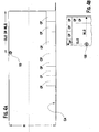
- UL Standard 1626 (Oct 2003) requires placing a selected sprinkler 100 over a protective area sub-divided into four quadrants with the sprinkler 100 placed in the center of the quadrants I-IV. A detailed layout of one quadrant is illustrated in Figure 4C .
- the coverage area CA is generally the product of a coverage width CW and length CL such as, for example, 1,67 m 2 (18 feet by 18 feet) or 1,86 m 2 (20 feet by 20 feet).
- the length L of the quadrant III is generally the one-half the coverage length CL and the width W is generally one-half the coverage width CW, where each square foot of the quadrant is covered by collection pans of one-square foot area with the top of each collection being about 2,44 m (eight feet) below a generally flat ceiling of the coverage area and the amount of fluid collected is about 0,007 liters per minute per m 2 (0.02 gallons per minute per square foot) for any of the collection pans except that no more than four collection pans for each quadrant receive at least 0,005 liters per minute per m 2 (0.015 gallons per minute per square foot.
- Water or a suitable fire fighting fluid is supplied to the selected sprinkler 100 at a desired rate with the sprinkler 100 being tested via a 25,4 mm (one-inch) internal diameter pipe with a T-fitting having an outlet at substantially the same internal diameter as the inlet 26A of the selected sprinkler 100.
- the duration of the test is twenty-minutes and at the completion of the test, the water collected by the collection pan CP (as delineated by the square like grid) is measured to determine if the amount deposited complies with the minimum density requirement for each coverage area.
- the nub 42 is believed to allow the break up of the flow stream extending from the outlet 26B perpendicular to the frame arms 14 in order to meet an 8-foot spacing between sprinklers in the operational test of Section 22 of UL 1626 (Oct 2003).
- the closed ended slot 40 is believed to provide for a sufficient fluid distribution over the test coverage area perpendicular to the frame arms 14.
- the close-ended slot chamfer 40A on the second end of each closed ended slots also contributes to the sprinkler 100 meeting the coverage area distribution requirements for this test. It is believed that each close-ended slot chamfer 40A allows a collection pan CP perpendicular to the frame arms 14 and furthest to the frame arms 14 to receive a sufficient fluid quantity to meet the requirements of this test.
- the features described above in relation to the deflector assembly 18 allows the sprinkler to provide a flow rate of 72 liters per minute (19 gallons per minute) of water at a pressure of less than 0,69 bar (10 pounds per square inch gauge) fed to the inlet 26A so that a sufficient density of water is provided to a coverage area of 1,67 m 2 (18 feet by 18 feet) under both the vertical and horizontal distribution tests of UL 1626 (Oct 2003).
- the features described above in relation to the deflector assembly 18 also allow the sprinkler to provide a flow rate of 83,4 liters (22 gallons) per minute at a pressure of less than 0,69 bar (10 pounds) fed to the inlet for a coverage area of 1,86 m 2 (20 feet by 20 feet) under both the vertical and horizontal distribution tests of UL 1626 (Oct 2003).
- actual fire tests can also be performed in accordance with UL Standard 1626 (Oct 2003) for the preferred embodiments.
- three tests arrangement can be utilized within a room with nominally 2,44 m (eight feet) generally horizontal or flat ceiling and simulated furniture so that the tested residential fire sprinkler 100 can limit temperatures at four different locations to specified temperatures. Details of these tests are shown and described in UL 1626 (Oct 2003).
- the annular plate 20 of the sprinkler 100 is provided with the dished and multiple tapered portions that are believed to allow the preferred sprinkler 100 to be used in at least three different mounting configurations such as, for example, a pendent, recessed pendent, or concealed pendent mounting configurations.
- the preferred embodiment can be installed so that the deflector first plate surface 20A exposed to the outlet 26B is about 38,1 to 101,6 mm (1.5 to 4 inches) from a ceiling.
- the first plate surface 20A of the defector can be about 35,6 mm (1.4 inch) from the ceiling surface with adjustments of 6,4 mm (1 ⁇ 4 inches) in any one vertical direction,
- the deflector is located at about 6,4 mm (1 ⁇ 4 inch) from the ceiling surface.
- the preferred embodiments disclosed herein are the first residential sprinklers 100 with a K-factor greater than 70,7 (4.9) that can be used in all three mounting configurations. This multiple mounting capability of the preferred embodiment is believed to be advantageous to a fire protection designer because one type of sprinkler can be used regardless of the aesthetics and functional requirements of the system designer.
- the combinations of features can also be provided with variations in each of these features to allow a 6,4 mm (3 ⁇ 4 inch) threaded sprinkler body with these variations to be listed under UL 1626 (Oct 2003) at a minimum operating pressure of less than 0,7 bar (10 pounds per square inch gauge) for a coverage area of at least 30,13 m 2 (324 square feet) and installed in accordance with NFPA 13, 13D, and 13R (2002).
- the taper angles ⁇ 1 , ⁇ 2 , and ⁇ 3 would include, for example, a variation in the particular relationship of the taper angles ⁇ 1 , ⁇ 2 , and ⁇ 3 for the dished annular plate 20 as a function of the installation; the number of tines 24A along with variations in the width between the tines 24A, radius of curvature and location of the terminal portion 24A3 of each open-ended slot 24B; the nub 42 can be in a configuration other than cylindrical while its height above the plate surface 20A may be varied depending on the installation sprinklers in a design; the length or width of the close-ended slots 40 can be smaller or larger depending on the targeting of fluid spray below the deflector 20; the close-ended slots 40 may be offset instead of being aligned with each other along the first axis X-X; the chamfer 40A of the close-ended slots 40 can be modified to provide for a different taper angle or a combination of taper angles; the through-opening 44 can be in a configuration other than
- the preferred embodiments of the sprinkler 100 are able to pass all of the performance tests required by UL 1626 (Oct 2003), the preferred embodiments are able to be listed by a listing authority, such as, for example, UL, for design and installation as a residential fire sprinkler, as defined in Section 3.6.2.10 of NFPA 13 (2002).
- a listing authority such as, for example, UL
- the preferred embodiments can be installed in any one of three different mounting configurations, in a residential fire protection system, in accordance with NFPA 13, 13D and 13R (2002) at lower minimum design pressures for design protection area of 30,13 m 2 (324 square feet) or greater.
- At least the annular plate 20, frame arm, slots and tines are preferably the means for distributing fluid over a coverage area of a residential dwelling unit so that the sprinkler can be installed in accordance with the 2002 Edition of National Fire Protection Association Standards 13, 13D and 13R to provide a suitable density for a minimum design pressure of less than 0,97 bar (14 pounds per square inch gauge) where a design protection area is about 37,2 m 2 (400 square feet) with a maximum distance of a generally linear side of the design protection area being no greater than 6,09 m (20 feet). And with the lower minimum design pressures, the preferred embodiments can be utilized in the design of fire protection system for coverage area of 30,13 m 2 (324 square feet) of greater at approximately 30 percent lower design pressure than known residential fire sprinklers.
Landscapes
- Health & Medical Sciences (AREA)
- Public Health (AREA)
- Business, Economics & Management (AREA)
- Emergency Management (AREA)
- Fire-Extinguishing By Fire Departments, And Fire-Extinguishing Equipment And Control Thereof (AREA)
- Catching Or Destruction (AREA)
Applications Claiming Priority (2)
| Application Number | Priority Date | Filing Date | Title |
|---|---|---|---|
| US11/000,128 US7201234B2 (en) | 2004-12-01 | 2004-12-01 | Residential fire sprinkler |
| PCT/US2005/042816 WO2006060287A1 (en) | 2004-12-01 | 2005-11-29 | Residential fire sprinkler |
Publications (3)
| Publication Number | Publication Date |
|---|---|
| EP1817085A1 EP1817085A1 (en) | 2007-08-15 |
| EP1817085A4 EP1817085A4 (en) | 2008-12-31 |
| EP1817085B1 true EP1817085B1 (en) | 2012-04-11 |
Family
ID=36565364
Family Applications (1)
| Application Number | Title | Priority Date | Filing Date |
|---|---|---|---|
| EP05852223A Expired - Lifetime EP1817085B1 (en) | 2004-12-01 | 2005-11-29 | Residential fire sprinkler |
Country Status (11)
| Country | Link |
|---|---|
| US (3) | US7201234B2 (da) |
| EP (1) | EP1817085B1 (da) |
| CN (1) | CN101175538B (da) |
| AT (1) | ATE552893T1 (da) |
| AU (1) | AU2005312103B2 (da) |
| CA (2) | CA2827495C (da) |
| DK (1) | DK1817085T3 (da) |
| ES (1) | ES2391149T3 (da) |
| NZ (1) | NZ555399A (da) |
| SG (1) | SG160349A1 (da) |
| WO (1) | WO2006060287A1 (da) |
Families Citing this family (38)
| Publication number | Priority date | Publication date | Assignee | Title |
|---|---|---|---|---|
| US7363987B2 (en) * | 2005-03-31 | 2008-04-29 | William Grant | Sprinkler system for converting non-sprinklered buildings |
| DE602007009105D1 (de) * | 2006-07-07 | 2010-10-21 | Antelco Pty Ltd | Sprühvorrichtung |
| AU2008242614A1 (en) * | 2007-04-19 | 2008-10-30 | Tyco Fire Products Lp | Extended coverage pendent sprinkler |
| US7762349B2 (en) | 2007-11-21 | 2010-07-27 | Black & Decker Inc. | Multi-speed drill and transmission with low gear only clutch |
| US7770660B2 (en) | 2007-11-21 | 2010-08-10 | Black & Decker Inc. | Mid-handle drill construction and assembly process |
| US7735575B2 (en) | 2007-11-21 | 2010-06-15 | Black & Decker Inc. | Hammer drill with hard hammer support structure |
| WO2010057029A1 (en) * | 2008-11-13 | 2010-05-20 | The Reliable Automatic Sprinkler Co., Inc. | Fire protection method and system for sloped ceilings |
| US8181709B2 (en) * | 2009-01-13 | 2012-05-22 | Kofulso Co., Ltd. | Mounting structure for sprinkler head |
| US9132305B2 (en) * | 2009-03-17 | 2015-09-15 | The Viking Corporation | Fire protection sprinkler |
| USD607084S1 (en) | 2009-03-25 | 2009-12-29 | The Viking Corporation | Deflector for fire protection sprinkler |
| FI121590B (fi) * | 2009-06-30 | 2011-01-31 | Marioff Corp Oy | Suihkutuspää |
| US10532237B2 (en) * | 2010-08-05 | 2020-01-14 | Victaulic Company | Dual mode agent discharge system with multiple agent discharge capability |
| US20150165252A1 (en) * | 2012-05-30 | 2015-06-18 | The Reliable Automatic Sprinkler Co., Inc. | Visual assembly aid for sprinkler and method for use |
| US9265981B2 (en) * | 2012-12-12 | 2016-02-23 | The Viking Corporation | Pip cap assembly for a fire protection sprinkler |
| US9849319B2 (en) | 2013-03-13 | 2017-12-26 | Tyco Fire Products Lp | Fire protection sprinkler assembly |
| US9849320B2 (en) | 2013-03-13 | 2017-12-26 | Tyco Fire Products Lp | Fire protection sprinkler assembly |
| AU2014248512A1 (en) | 2013-03-13 | 2015-11-05 | Tyco Fire Products Lp | CPVC sprinkler assembly with support member |
| WO2014151977A2 (en) | 2013-03-14 | 2014-09-25 | Tyco Fire Products Lp | Fire protection sprinkler assembly |
| AU2014285092A1 (en) | 2013-07-03 | 2015-12-24 | Tyco Fire Products Lp | Self-sealing sprinkler seal and methods |
| EP3086864B1 (en) * | 2013-12-23 | 2023-10-04 | Tyco Fire Products LP | Controlled system and methods for storage fire protection |
| WO2016019392A1 (en) | 2014-08-01 | 2016-02-04 | The Reliable Automatic Sprinkler Co., Inc. | Horizontal sidewall sprinkler |
| WO2016196836A1 (en) * | 2015-06-02 | 2016-12-08 | Tyco Fire Products Lp | An upright fire protection sprinkler |
| USD771603S1 (en) * | 2015-08-10 | 2016-11-15 | Joseph A. Ruggles | Portable television stand |
| WO2017097361A1 (en) | 2015-12-10 | 2017-06-15 | Marioff Corporation Oy | Water mist nozzle for a fire suppression system |
| US10238903B2 (en) * | 2016-04-14 | 2019-03-26 | The Viking Corporation | Residential concealed sprinkler |
| PE20190531A1 (es) | 2016-09-09 | 2019-04-11 | Victaulic Co Of America | Rociador y deflector de extincion de incendios |
| US10898746B2 (en) | 2016-09-16 | 2021-01-26 | The Reliable Automatic Sprinkler Co. Inc. | Fire protection nozzle, fire protection sprinkler, fire protection systems, and methods of manufacturing a fire protection nozzle and a fire protection sprinkler |
| DE202017105705U1 (de) | 2017-09-20 | 2018-12-21 | Job Lizenz Gmbh & Co. Kg | Sprinklerkopf |
| WO2019106713A1 (ja) * | 2017-11-28 | 2019-06-06 | 千住スプリンクラー株式会社 | スプリンクラーヘッド |
| WO2019173067A1 (en) * | 2018-03-08 | 2019-09-12 | Victaulic Company | Fire suppression sprinkler and deflector |
| US12194326B2 (en) | 2018-08-17 | 2025-01-14 | Minimax Viking Patent Management Gmbh | Automatic fire sprinklers, systems and methods for suppression fire protection of high hazard commodities including commodities stored in rack arrangements beneath ceilings of up to fifty-five feet in height |
| US11007388B2 (en) * | 2018-08-17 | 2021-05-18 | Viking Group, Inc. | Automatic fire sprinklers, systems and methods for suppression fire protection of high hazard commodities including commodities stored in rack arrangements beneath ceilings of up to fifty-five feet in height |
| US11583873B2 (en) * | 2019-04-23 | 2023-02-21 | Tyco Fire Products Lp | Sprinkler head with vane deflector |
| CA3143778A1 (en) * | 2019-07-19 | 2021-01-28 | Tyco Fire Products Lp | Sprinkler head adapter |
| CN111184971A (zh) * | 2020-02-18 | 2020-05-22 | 苏州海星海事装备股份有限公司 | 一种反射空心锥形消防水炮喷嘴 |
| WO2022040101A1 (en) * | 2020-08-19 | 2022-02-24 | Minimax Viking Research & Development Gmbh | Trigger assemblies for automatic fire protection sprinklers |
| US20220331632A1 (en) * | 2021-04-13 | 2022-10-20 | Tyco Fire Products Lp | Systems and methods of fire protection sprinklers |
| CN116492757B (zh) * | 2023-05-17 | 2025-09-19 | 江西省天玉油脂有限公司 | 一种用于油脂制造的精炼设备 |
Family Cites Families (15)
| Publication number | Priority date | Publication date | Assignee | Title |
|---|---|---|---|---|
| US2135138A (en) * | 1937-05-28 | 1938-11-01 | Rockwood Sprinkler Co Massachusetts | Automatic sprinkler and deflector therefor |
| US2534066A (en) * | 1949-11-30 | 1950-12-12 | Globe Automatic Sprinkler Co | Sprinkler head and mounting therefor |
| US3603512A (en) * | 1968-09-25 | 1971-09-07 | Alexander Jan Ham | Spray nozzles |
| US4580729A (en) * | 1985-01-22 | 1986-04-08 | Grinnell Fire Protection Systems Co., Inc. | Sprinkler head with improved spray uniformity |
| US5609211A (en) * | 1991-09-30 | 1997-03-11 | Central Sprinkler Company | Extended coverage automatic ceiling sprinkler |
| US5366022A (en) * | 1991-09-30 | 1994-11-22 | Central Sprinkler Corporation | Extended coverage ceiling sprinklers and systems |
| CN2220880Y (zh) * | 1995-05-12 | 1996-02-28 | 沙桂香 | 自动洒水喷头 |
| US5865256A (en) * | 1996-09-25 | 1999-02-02 | Grinnell Corporation | Deflectors for pendent-type fire protection sprinklers |
| US5839667A (en) * | 1997-03-12 | 1998-11-24 | Grinnell Corporation | Pendent-type diffuser impingement water mist nozzle |
| US6059044A (en) * | 1998-05-15 | 2000-05-09 | Grinnell Corporation | Fire protection sprinkler and deflector |
| US6026907A (en) * | 1998-12-08 | 2000-02-22 | The Reliable Automatic Sprinkler, Co. Inc. | Fast response residential sprinkler arrangement |
| US6276460B1 (en) * | 2000-05-23 | 2001-08-21 | Reliable Automatic Sprinkler Co., Inc. | Residental sprinkler arrangement |
| US6516893B2 (en) * | 2001-06-05 | 2003-02-11 | The Reliable Automatic Sprinkler Co.,Inc. | Residential sprinkler arrangement |
| US6854668B2 (en) * | 2002-04-29 | 2005-02-15 | Victaulic Company Of America | Extended coverage ordinary hazard sprinkler system |
| CA2458421C (en) | 2004-02-12 | 2009-06-30 | The Viking Corporation | Fast response sprinkler assembly for a fire extinguishing system |
-
2004
- 2004-12-01 US US11/000,128 patent/US7201234B2/en not_active Expired - Lifetime
-
2005
- 2005-11-29 ES ES05852223T patent/ES2391149T3/es not_active Expired - Lifetime
- 2005-11-29 EP EP05852223A patent/EP1817085B1/en not_active Expired - Lifetime
- 2005-11-29 CA CA2827495A patent/CA2827495C/en not_active Expired - Lifetime
- 2005-11-29 DK DK05852223.6T patent/DK1817085T3/da active
- 2005-11-29 AT AT05852223T patent/ATE552893T1/de active
- 2005-11-29 SG SG201001349-8A patent/SG160349A1/en unknown
- 2005-11-29 CN CN200580047620XA patent/CN101175538B/zh not_active Expired - Lifetime
- 2005-11-29 AU AU2005312103A patent/AU2005312103B2/en not_active Expired
- 2005-11-29 WO PCT/US2005/042816 patent/WO2006060287A1/en not_active Ceased
- 2005-11-29 CA CA2588365A patent/CA2588365C/en not_active Expired - Lifetime
- 2005-11-29 NZ NZ555399A patent/NZ555399A/en not_active IP Right Cessation
-
2007
- 2007-03-30 US US11/694,106 patent/US7658231B2/en not_active Expired - Lifetime
-
2010
- 2010-01-15 US US12/688,159 patent/US8074725B2/en not_active Expired - Lifetime
Also Published As
| Publication number | Publication date |
|---|---|
| ES2391149T3 (es) | 2012-11-22 |
| CA2588365C (en) | 2013-11-19 |
| US20100116514A1 (en) | 2010-05-13 |
| CN101175538A (zh) | 2008-05-07 |
| US7201234B2 (en) | 2007-04-10 |
| AU2005312103B2 (en) | 2012-07-26 |
| HK1120454A1 (en) | 2009-04-03 |
| WO2006060287A1 (en) | 2006-06-08 |
| CN101175538B (zh) | 2012-10-24 |
| CA2827495A1 (en) | 2006-06-08 |
| US8074725B2 (en) | 2011-12-13 |
| US7658231B2 (en) | 2010-02-09 |
| NZ555399A (en) | 2011-02-25 |
| US20070169945A1 (en) | 2007-07-26 |
| AU2005312103A1 (en) | 2006-06-08 |
| SG160349A1 (en) | 2010-04-29 |
| ATE552893T1 (de) | 2012-04-15 |
| EP1817085A1 (en) | 2007-08-15 |
| US20060113092A1 (en) | 2006-06-01 |
| EP1817085A4 (en) | 2008-12-31 |
| CA2827495C (en) | 2016-09-13 |
| CA2588365A1 (en) | 2006-06-08 |
| DK1817085T3 (da) | 2012-07-23 |
Similar Documents
| Publication | Publication Date | Title |
|---|---|---|
| EP1817085B1 (en) | Residential fire sprinkler | |
| US8353356B2 (en) | Residential flat plate concealed sprinkler | |
| USRE46349E1 (en) | Residential dry sprinkler design method and system | |
| CA2658789C (en) | Residential sidewall fire sprinkler | |
| HK1120454B (en) | Residential fire sprinkler | |
| HK1124003B (en) | Residential flat plate concealed sprinkler |
Legal Events
| Date | Code | Title | Description |
|---|---|---|---|
| PUAI | Public reference made under article 153(3) epc to a published international application that has entered the european phase |
Free format text: ORIGINAL CODE: 0009012 |
|
| 17P | Request for examination filed |
Effective date: 20070524 |
|
| AK | Designated contracting states |
Kind code of ref document: A1 Designated state(s): AT BE BG CH CY CZ DE DK EE ES FI FR GB GR HU IE IS IT LI LT LU LV MC NL PL PT RO SE SI SK TR |
|
| DAX | Request for extension of the european patent (deleted) | ||
| A4 | Supplementary search report drawn up and despatched |
Effective date: 20081127 |
|
| RIC1 | Information provided on ipc code assigned before grant |
Ipc: A62C 37/14 20060101ALI20081121BHEP Ipc: A62C 31/02 20060101ALI20081121BHEP Ipc: A62C 37/08 20060101AFI20060609BHEP Ipc: B05B 1/26 20060101ALI20081121BHEP |
|
| 17Q | First examination report despatched |
Effective date: 20090206 |
|
| RAP1 | Party data changed (applicant data changed or rights of an application transferred) |
Owner name: TYCO FIRE PRODUCTS LP |
|
| GRAP | Despatch of communication of intention to grant a patent |
Free format text: ORIGINAL CODE: EPIDOSNIGR1 |
|
| GRAS | Grant fee paid |
Free format text: ORIGINAL CODE: EPIDOSNIGR3 |
|
| GRAA | (expected) grant |
Free format text: ORIGINAL CODE: 0009210 |
|
| AK | Designated contracting states |
Kind code of ref document: B1 Designated state(s): AT BE BG CH CY CZ DE DK EE ES FI FR GB GR HU IE IS IT LI LT LU LV MC NL PL PT RO SE SI SK TR |
|
| REG | Reference to a national code |
Ref country code: GB Ref legal event code: FG4D |
|
| REG | Reference to a national code |
Ref country code: CH Ref legal event code: EP |
|
| REG | Reference to a national code |
Ref country code: AT Ref legal event code: REF Ref document number: 552893 Country of ref document: AT Kind code of ref document: T Effective date: 20120415 |
|
| REG | Reference to a national code |
Ref country code: IE Ref legal event code: FG4D |
|
| REG | Reference to a national code |
Ref country code: DE Ref legal event code: R096 Ref document number: 602005033687 Country of ref document: DE Effective date: 20120606 |
|
| REG | Reference to a national code |
Ref country code: NL Ref legal event code: T3 |
|
| REG | Reference to a national code |
Ref country code: DK Ref legal event code: T3 |
|
| REG | Reference to a national code |
Ref country code: SE Ref legal event code: TRGR |
|
| REG | Reference to a national code |
Ref country code: AT Ref legal event code: MK05 Ref document number: 552893 Country of ref document: AT Kind code of ref document: T Effective date: 20120411 |
|
| LTIE | Lt: invalidation of european patent or patent extension |
Effective date: 20120411 |
|
| PG25 | Lapsed in a contracting state [announced via postgrant information from national office to epo] |
Ref country code: CY Free format text: LAPSE BECAUSE OF FAILURE TO SUBMIT A TRANSLATION OF THE DESCRIPTION OR TO PAY THE FEE WITHIN THE PRESCRIBED TIME-LIMIT Effective date: 20120411 Ref country code: IS Free format text: LAPSE BECAUSE OF FAILURE TO SUBMIT A TRANSLATION OF THE DESCRIPTION OR TO PAY THE FEE WITHIN THE PRESCRIBED TIME-LIMIT Effective date: 20120811 Ref country code: PL Free format text: LAPSE BECAUSE OF FAILURE TO SUBMIT A TRANSLATION OF THE DESCRIPTION OR TO PAY THE FEE WITHIN THE PRESCRIBED TIME-LIMIT Effective date: 20120411 Ref country code: LT Free format text: LAPSE BECAUSE OF FAILURE TO SUBMIT A TRANSLATION OF THE DESCRIPTION OR TO PAY THE FEE WITHIN THE PRESCRIBED TIME-LIMIT Effective date: 20120411 |
|
| REG | Reference to a national code |
Ref country code: ES Ref legal event code: FG2A Ref document number: 2391149 Country of ref document: ES Kind code of ref document: T3 Effective date: 20121122 |
|
| PG25 | Lapsed in a contracting state [announced via postgrant information from national office to epo] |
Ref country code: PT Free format text: LAPSE BECAUSE OF FAILURE TO SUBMIT A TRANSLATION OF THE DESCRIPTION OR TO PAY THE FEE WITHIN THE PRESCRIBED TIME-LIMIT Effective date: 20120813 Ref country code: GR Free format text: LAPSE BECAUSE OF FAILURE TO SUBMIT A TRANSLATION OF THE DESCRIPTION OR TO PAY THE FEE WITHIN THE PRESCRIBED TIME-LIMIT Effective date: 20120712 Ref country code: LV Free format text: LAPSE BECAUSE OF FAILURE TO SUBMIT A TRANSLATION OF THE DESCRIPTION OR TO PAY THE FEE WITHIN THE PRESCRIBED TIME-LIMIT Effective date: 20120411 Ref country code: SI Free format text: LAPSE BECAUSE OF FAILURE TO SUBMIT A TRANSLATION OF THE DESCRIPTION OR TO PAY THE FEE WITHIN THE PRESCRIBED TIME-LIMIT Effective date: 20120411 |
|
| PG25 | Lapsed in a contracting state [announced via postgrant information from national office to epo] |
Ref country code: RO Free format text: LAPSE BECAUSE OF FAILURE TO SUBMIT A TRANSLATION OF THE DESCRIPTION OR TO PAY THE FEE WITHIN THE PRESCRIBED TIME-LIMIT Effective date: 20120411 Ref country code: SK Free format text: LAPSE BECAUSE OF FAILURE TO SUBMIT A TRANSLATION OF THE DESCRIPTION OR TO PAY THE FEE WITHIN THE PRESCRIBED TIME-LIMIT Effective date: 20120411 Ref country code: EE Free format text: LAPSE BECAUSE OF FAILURE TO SUBMIT A TRANSLATION OF THE DESCRIPTION OR TO PAY THE FEE WITHIN THE PRESCRIBED TIME-LIMIT Effective date: 20120411 Ref country code: AT Free format text: LAPSE BECAUSE OF FAILURE TO SUBMIT A TRANSLATION OF THE DESCRIPTION OR TO PAY THE FEE WITHIN THE PRESCRIBED TIME-LIMIT Effective date: 20120411 Ref country code: CZ Free format text: LAPSE BECAUSE OF FAILURE TO SUBMIT A TRANSLATION OF THE DESCRIPTION OR TO PAY THE FEE WITHIN THE PRESCRIBED TIME-LIMIT Effective date: 20120411 |
|
| PLBE | No opposition filed within time limit |
Free format text: ORIGINAL CODE: 0009261 |
|
| STAA | Information on the status of an ep patent application or granted ep patent |
Free format text: STATUS: NO OPPOSITION FILED WITHIN TIME LIMIT |
|
| 26N | No opposition filed |
Effective date: 20130114 |
|
| REG | Reference to a national code |
Ref country code: DE Ref legal event code: R097 Ref document number: 602005033687 Country of ref document: DE Effective date: 20130114 |
|
| REG | Reference to a national code |
Ref country code: CH Ref legal event code: PL |
|
| PG25 | Lapsed in a contracting state [announced via postgrant information from national office to epo] |
Ref country code: BG Free format text: LAPSE BECAUSE OF FAILURE TO SUBMIT A TRANSLATION OF THE DESCRIPTION OR TO PAY THE FEE WITHIN THE PRESCRIBED TIME-LIMIT Effective date: 20120711 Ref country code: CH Free format text: LAPSE BECAUSE OF NON-PAYMENT OF DUE FEES Effective date: 20121130 Ref country code: LI Free format text: LAPSE BECAUSE OF NON-PAYMENT OF DUE FEES Effective date: 20121130 |
|
| REG | Reference to a national code |
Ref country code: IE Ref legal event code: MM4A |
|
| PG25 | Lapsed in a contracting state [announced via postgrant information from national office to epo] |
Ref country code: IE Free format text: LAPSE BECAUSE OF NON-PAYMENT OF DUE FEES Effective date: 20121129 |
|
| PG25 | Lapsed in a contracting state [announced via postgrant information from national office to epo] |
Ref country code: MC Free format text: LAPSE BECAUSE OF NON-PAYMENT OF DUE FEES Effective date: 20121130 Ref country code: TR Free format text: LAPSE BECAUSE OF FAILURE TO SUBMIT A TRANSLATION OF THE DESCRIPTION OR TO PAY THE FEE WITHIN THE PRESCRIBED TIME-LIMIT Effective date: 20120411 |
|
| PG25 | Lapsed in a contracting state [announced via postgrant information from national office to epo] |
Ref country code: LU Free format text: LAPSE BECAUSE OF NON-PAYMENT OF DUE FEES Effective date: 20121129 |
|
| PG25 | Lapsed in a contracting state [announced via postgrant information from national office to epo] |
Ref country code: HU Free format text: LAPSE BECAUSE OF FAILURE TO SUBMIT A TRANSLATION OF THE DESCRIPTION OR TO PAY THE FEE WITHIN THE PRESCRIBED TIME-LIMIT Effective date: 20051129 |
|
| REG | Reference to a national code |
Ref country code: FR Ref legal event code: PLFP Year of fee payment: 11 |
|
| REG | Reference to a national code |
Ref country code: FR Ref legal event code: PLFP Year of fee payment: 12 |
|
| REG | Reference to a national code |
Ref country code: FR Ref legal event code: PLFP Year of fee payment: 13 |
|
| PGFP | Annual fee paid to national office [announced via postgrant information from national office to epo] |
Ref country code: DK Payment date: 20201125 Year of fee payment: 16 |
|
| PGFP | Annual fee paid to national office [announced via postgrant information from national office to epo] |
Ref country code: BE Payment date: 20201127 Year of fee payment: 16 |
|
| REG | Reference to a national code |
Ref country code: DK Ref legal event code: EBP Effective date: 20211130 |
|
| PG25 | Lapsed in a contracting state [announced via postgrant information from national office to epo] |
Ref country code: BE Free format text: LAPSE BECAUSE OF NON-PAYMENT OF DUE FEES Effective date: 20211130 |
|
| REG | Reference to a national code |
Ref country code: BE Ref legal event code: MM Effective date: 20211130 |
|
| PG25 | Lapsed in a contracting state [announced via postgrant information from national office to epo] |
Ref country code: DK Free format text: LAPSE BECAUSE OF NON-PAYMENT OF DUE FEES Effective date: 20211130 |
|
| PGFP | Annual fee paid to national office [announced via postgrant information from national office to epo] |
Ref country code: NL Payment date: 20241126 Year of fee payment: 20 |
|
| PGFP | Annual fee paid to national office [announced via postgrant information from national office to epo] |
Ref country code: DE Payment date: 20241128 Year of fee payment: 20 |
|
| PGFP | Annual fee paid to national office [announced via postgrant information from national office to epo] |
Ref country code: FI Payment date: 20241126 Year of fee payment: 20 |
|
| PGFP | Annual fee paid to national office [announced via postgrant information from national office to epo] |
Ref country code: GB Payment date: 20241126 Year of fee payment: 20 |
|
| PGFP | Annual fee paid to national office [announced via postgrant information from national office to epo] |
Ref country code: FR Payment date: 20241126 Year of fee payment: 20 |
|
| PGFP | Annual fee paid to national office [announced via postgrant information from national office to epo] |
Ref country code: IT Payment date: 20241125 Year of fee payment: 20 Ref country code: ES Payment date: 20241218 Year of fee payment: 20 |
|
| PGFP | Annual fee paid to national office [announced via postgrant information from national office to epo] |
Ref country code: SE Payment date: 20241126 Year of fee payment: 20 |
|
| REG | Reference to a national code |
Ref country code: DE Ref legal event code: R071 Ref document number: 602005033687 Country of ref document: DE |
|
| REG | Reference to a national code |
Ref country code: NL Ref legal event code: MK Effective date: 20251128 |
|
| REG | Reference to a national code |
Ref country code: ES Ref legal event code: FD2A Effective date: 20251205 |
|
| REG | Reference to a national code |
Ref country code: GB Ref legal event code: PE20 Expiry date: 20251128 |
|
| PG25 | Lapsed in a contracting state [announced via postgrant information from national office to epo] |
Ref country code: ES Free format text: LAPSE BECAUSE OF EXPIRATION OF PROTECTION Effective date: 20251130 |