EP1816404A2 - Indoor unit of air conditioner - Google Patents
Indoor unit of air conditioner Download PDFInfo
- Publication number
- EP1816404A2 EP1816404A2 EP20060256320 EP06256320A EP1816404A2 EP 1816404 A2 EP1816404 A2 EP 1816404A2 EP 20060256320 EP20060256320 EP 20060256320 EP 06256320 A EP06256320 A EP 06256320A EP 1816404 A2 EP1816404 A2 EP 1816404A2
- Authority
- EP
- European Patent Office
- Prior art keywords
- indoor unit
- cabinet
- air
- outlet
- vane
- Prior art date
- Legal status (The legal status is an assumption and is not a legal conclusion. Google has not performed a legal analysis and makes no representation as to the accuracy of the status listed.)
- Granted
Links
Images


Classifications
-
- F—MECHANICAL ENGINEERING; LIGHTING; HEATING; WEAPONS; BLASTING
- F24—HEATING; RANGES; VENTILATING
- F24F—AIR-CONDITIONING; AIR-HUMIDIFICATION; VENTILATION; USE OF AIR CURRENTS FOR SCREENING
- F24F1/00—Room units for air-conditioning, e.g. separate or self-contained units or units receiving primary air from a central station
- F24F1/0007—Indoor units, e.g. fan coil units
- F24F1/0011—Indoor units, e.g. fan coil units characterised by air outlets
-
- F—MECHANICAL ENGINEERING; LIGHTING; HEATING; WEAPONS; BLASTING
- F24—HEATING; RANGES; VENTILATING
- F24F—AIR-CONDITIONING; AIR-HUMIDIFICATION; VENTILATION; USE OF AIR CURRENTS FOR SCREENING
- F24F1/00—Room units for air-conditioning, e.g. separate or self-contained units or units receiving primary air from a central station
- F24F1/0007—Indoor units, e.g. fan coil units
- F24F1/0043—Indoor units, e.g. fan coil units characterised by mounting arrangements
- F24F1/0057—Indoor units, e.g. fan coil units characterised by mounting arrangements mounted in or on a wall
-
- F—MECHANICAL ENGINEERING; LIGHTING; HEATING; WEAPONS; BLASTING
- F24—HEATING; RANGES; VENTILATING
- F24F—AIR-CONDITIONING; AIR-HUMIDIFICATION; VENTILATION; USE OF AIR CURRENTS FOR SCREENING
- F24F1/00—Room units for air-conditioning, e.g. separate or self-contained units or units receiving primary air from a central station
- F24F1/0007—Indoor units, e.g. fan coil units
- F24F1/0068—Indoor units, e.g. fan coil units characterised by the arrangement of refrigerant piping outside the heat exchanger within the unit casing
-
- F—MECHANICAL ENGINEERING; LIGHTING; HEATING; WEAPONS; BLASTING
- F24—HEATING; RANGES; VENTILATING
- F24F—AIR-CONDITIONING; AIR-HUMIDIFICATION; VENTILATION; USE OF AIR CURRENTS FOR SCREENING
- F24F13/00—Details common to, or for air-conditioning, air-humidification, ventilation or use of air currents for screening
- F24F13/20—Casings or covers
- F24F2013/207—Casings or covers with control knobs; Mounting controlling members or control units therein
Definitions
- the present invention relates to an indoor unit of an air conditioner, and more particularly, to an indoor unit of an air conditioner, in which a safety net at an outlet is formed of metal wire, and electric cables are laid on a groove in an outlet unit isolated from a space air is to be blown thereto.
- the air conditioner serving as a room heater, a room cooler, or an air purifier for cooling/heating a room, or purifying room air, provides human being a better room environment.
- an air conditioner has been developed, which is provided with a turbo-fan to minimize a thickness of a cabinet thereof to permit the air conditioner to be mounted on a wall of the room like a picture frame.
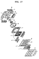
- FIG. 17 illustrates an exploded perspective view of a related art air conditioner.
- the related art air conditioner is provided with a thin rectangular cabinet 1 with an opened front, a fan 2 in the cabinet 1, a heat exchanger 3 in front of the fan 2, a front panel 4 with an air inlet 4a in front of the heat exchanger 3, an orifice 5 which is an air outlet between the cabinet 1 and the front panel 4, and a front grill 6 rotatably mounted in front of the front panel 4, for opening/closing the air inlet 4a.
- the fan 2 is provided with a turbo fan 2a and a motor 2b for rotating the turbo fan 2a, not only for minimizing thickness of the cabinet 1, but also for discharging air drawn through the air inlet 4a in a circumferential direction.
- the orifice 5 between the heat exchanger 3 and the fan 2, guides the air from the air inlet 4a to the fan 2.
- a filter 7 for filtering air from the air inlet 4a
- a control box 8 which is a control unit.
- outlet units 9 for guiding a direction of air blow at the time of air discharge from an inside of the cabinet 1.
- the outlet unit 9 has an air outlet on an inner side with a plurality of grills 9a for guiding an air blow direction, and a motor (not shown) for operating vanes 9b.
- the plurality of grills 9a at the outlet unit 9 reduces a flow speed of air being discharged.
- the invention provides an indoor unit of an air conditioner that includes a cabinet, and an outlet unit mounted to the cabinet for guiding air being discharged from an inside, wherein the outlet unit includes a body mounted to the cabinet, the body having an air outlet, a vane mounted to the body for opening/closing the air outlet, and a safety net detachably mounted to the air outlet of the body.
- the safety net is forcibly placed in the body, formed of steel, and constructed of rods crossed with one another.
- the body has holes and ends of the rods are placed in the holes in the body respectively, and the body includes a stopper projected toward an inside of the air outlet for limiting movement of the vane.
- an indoor unit of an air conditioner includes a cabinet, and an outlet unit mounted to the cabinet for guiding air being discharged from an inside, wherein the outlet unit includes a body mounted to the cabinet, the body having an air outlet, a vane mounted to the body for opening/closing the air outlet, and a stopper projected from the body toward an inside of the air outlet for limiting movement of the vane.
- the stopper has a rib shape, the body is provided with a safety net detachably mounted to the air outlet, and the safety net is positioned on an inner side of the stopper.
- the body includes a rib in the middle of a length of the body connected to upper/lower walls thereof, and the rib is projected to an inner side of the air outlet for limiting movement of the vane.
- the vane has an inner edge which is moved toward an inner side of the body to open the air outlet.
- an indoor unit of an air conditioner includes a cabinet, and an outlet unit mounted to the cabinet for guiding air being discharged from an inside, wherein the outlet unit includes a body mounted to the cabinet, the body having an air outlet, and an electric cable placing space in the body.
- the indoor unit further includes a vane mounted to the body for opening/closing the air outlet, and the electric cable placing space is positioned between the cabinet and the body for isolating the electric cable placing space from an air flowing space.
- the electric cable placing space is a groove in the body, forcibly inserted in the groove, or secured to the groove held by the groove.
- the body has a rib extended in the groove for preventing the electric cable from falling off the groove, and the rib has an end in contact with the cabinet for closing the electric cable placing space.
- the indoor unit has outfit
- the outlet unit includes a vane mounted to the body for opening/closing the air outlet, and driving means for driving the vane, wherein the electric cable placing space has a cable placed therein for connecting the outfit to the driving means.
- the indoor unit of an air conditioner of the present invention minimizes a resistance to the air being discharged owing to a safety net of metal rods on an air outlet, and prevents foreign matters or a user's hand from entering into the cabinet owing to the safety net, the electric cable from being in contact with flowing air during operation of the indoor unit to reduce a flow resistance of air.
- FIGS. 1 and 2 illustrate exploded perspective views each showing an indoor unit of an air conditioner in accordance with a preferred embodiment of the present invention
- FIG. 3 illustrates an exploded perspective view of a picture frame panel in accordance with a preferred embodiment of the present invention
- FIG. 4 illustrates an exploded perspective view of a deco-frame of a picture frame panel of the present invention
- FIG. 5 illustrates sections showing the steps of a process for assembling a picture frame panel in accordance with a preferred embodiment of the present invention
- FIG. 6 illustrates a perspective view of a deco-frame with fastening portions in accordance with a preferred embodiment of the present invention.
- the air conditioner in accordance with a preferred embodiment of the present invention includes a cabinet 10 forming an exterior of the indoor unit, a front panel 20 mounted to a front of the cabinet 10, and a picture frame panel 30 mounted on the front panel 20 spaced from the front panel 20.
- the front panel 20 has a central air inlet 15, and is fastened to the cabinet 10.
- the cabinet 10 has at least one air outlet 16 for discharge of air.
- the picture frame panel 30 is mounted in front of the front panel 20, spaced a predetermined distance from the front panel 20 to form a gap through which air moves toward the air inlet 15.
- the indoor unit includes a base 12 to be mounted on a wall of a room, a fan 14 on the base 12 for drawing/discharging room air, and an orifice 13 for guiding air from the air inlet 15 to the fan 14.
- the fan 14 between the base 12 and the orifice 13 guides the air from the air inlet 15 to the air outlet 16 entirely.
- the fan 14 is a centrifugal fan for discharging air from the orifice 13 in a circumferential direction.
- each of the air outlets 16 has an outlet unit 40 mounted thereon for opening/closing the air outlet 16.
- the air outlet 16 on an underside of the base 12 also has the outlet unit 40 mounted thereon for guiding outlet air into the room opened/closed by the control unit of the indoor unit.
- the base 12 is fixedly secured to the wall of the room with a bracket on a back side.
- an air guide 18 for guiding the air from the fan 14 to the air outlets 16 on both sides of the base 12.
- a heat exchanger 50 for making heat exchange with room air for cooling/heating the room air, and under the heat exchanger 50, there is a drain pan 100 for holding and draining condensed water formed at the heat exchanger 50.
- the heat exchanger 50 is secured to the front panel 20 or the orifice 13, and has a connection pipe 52 at one side for connection to a refrigerant pipe line (not shown) lead from an outside of the indoor unit.
- the heat exchanger 50 has a plasma filter 160 on a front.
- the front panel 20 in front of the heat exchanger 50 is fastened to the base 12.
- the fastening of the front panel 20 to the base 12 forms the air outlet 16 on which the outlet unit 40 is mounted.
- the cabinet 10 has pipe covers 11 mounted on corners to form a portion of an exterior of the indoor unit as the pipe covers 11 are mounted to corners of the base 12.
- the pipe covers 11 are mounted to a plurality of corners of the four corners of the cabinet 10, through which the external refrigerant pipe line is lead into the cabinet 10.
- the picture frame panel 30 includes a picture frame base 32, and a picture frame assembly rotatably hinged on the picture frame base 32.
- the picture frame assembly includes a deco-frame 34 hinged on the picture frame base 32, a transparent plate 35 placed in the deco-frame 34, a deco 36 for surrounding and holding the deco-frame 34 and the transparent plate 35 at a time, and a display window 38 in the deco-frame 34.
- the transparent plate 35 is formed of transparent acryl, or glass, and positioned on a front of the picture frame base 32 for exposing a picture or a photograph attached to the picture frame base 32.
- the deco-frame 34 is mounted on a periphery of the transparent plate 35 for securing the transparent plate 35.
- the deco-frame 34 includes four members 34a, 34b, 34c, and 34d for making close contact to four sides of the transparent plate 35, each of which are assembled together before mounting.
- one member 34a of the deco-frame 34 has a hole 34a' and the other member 34b to be coupled thereto has a boss 34b' to be placed in the hole 34a'.
- a fastening member (not shown) is fastened to the boss 34b' after the deco 36 is assembled, to put the deco-frame 34 close to the deco 36.
- the members 34a, and 34b of the deco-frame 34 have outer edges 33 bent forward for surrounding an edge of the transparent plate 35.
- the hinge hole 31a is extended in a lateral direction at an upper side of the deco-frame 34 so that the picture frame assembly can turn around a top edge.
- the projection 31 connects the picture frame base 32 to the picture frame assembly with a hinge as the projection is placed in a slot (not shown) in the picture frame base 32 and a pin (not shown) is passed through the slot and the projection 31.
- the display window 38 On a lower side of the deco-frame 34, there is the display window 38 connected to the outfit unit 150 for displaying a signal.
- the display window 38 between a lower side member and a right side member 34b of the deco-frame 34 is mounted at a lower side of a right side of the drawing, and the lower member 36c of the deco 36 has a hole 36c' for exposing the display window 38.
- the display window 38 may be a flat display unit, such as an LCD.
- the display window 38 displays an operation state of the indoor unit, or an environment of the room, or the like.
- the deco 36 for surrounding and holding edges both of the deco-frame 34 and the transparent plate 35 at a time, has a ' ⁇ ' section with one opened side facing the transparent window.
- the deco 36 has four members 36a, 36b, 36c, and 36d for surrounding four edges of the transparent plate 35 at a time.
- a front side blade 37a of the deco 36 is made to be in close contact with the transparent plate 35, and a rear side blade 37b of the deco 36 is made to be in close contact with the deco-frame 34.
- the rear side blade 37b of the deco 36 is formed long enough to cover the hole 34a'/boss 34b' portions to which the members 36a and 36b of the deco-frame 34 are engaged.
- the rear side blade 37b of the deco 36 has a hole 37c for placing a fastening member 39 therein, and the fastening member 39 placed through the hole 37c of the deco 36 is placed in the boss 34b' of the deco-frame 34 after the fastening member 39 is placed through the hole 37c. As an inserted depth of the fastening member 39 becomes the deeper, the fastening member 39 presses the deco-frame 34 onto the transparent plate 35.
- the hole 37c in the deco 36 has a thread formed thereon for fastening with the fastening member 39, and an end of the fastening member 39 pushes the deco-frame 34 toward the transparent plate 35.
- the front side blade 37a of the deco 36 is long enough to make the deco-frame 34 invisible through the transparent plate 35, the hole 36c' in the deco 36 matches with the display window 38.
- Assembly of the picture frame panel 30 of the present invention is efficient because the fastening member 39 presses the deco-frame 34 onto the transparent plate 35 at the time the fastening member 39 is fastened, and fastening of the deco 36 and the deco-plate 34 is made at a time.
- FIG. 7 illustrates a front view of a front panel in accordance with a preferred embodiment of the present invention
- FIG. 8 illustrates a front view of a front panel in accordance with a preferred embodiment of the present invention, having a service cover removed therefrom
- FIG. 9 illustrates an exploded perspective view of a cabinet and a front panel in accordance with a preferred embodiment of the present invention
- FIG. 10 illustrates a perspective view a cabinet and a front panel assembled together in accordance with a preferred embodiment of the present invention.
- the front panel 20 includes the air inlet 15 at a center, and a service cover 24 under the air inlet 15 for covering a portion of an inside of the cabinet 10.
- the service cover 24 is a portion of an exterior of the front panel 20.
- the service cover 24 is detachably mounted on the front panel 20 with a hook 27a and a hole 17a.
- the service cover 24 and the drain pan 100 are fastened together and is fastened to the front panel 20 with a bolt (not shown) or a screw (not shown).
- the service cover 24 is fastened to the front panel 20, such that one end 24a thereof is positioned in front of a lower connection pipe 52 of the heat exchanger for covering the connection pipe 52, and the other end covers a terminal box 155 for supplying power to the outfit unit 150.
- the terminal box 155 is separate from the outfit unit 150, and connected with cable for supplying power.
- the terminal box 155 covered with the service cover 14, can be repaired only after removing the service cover 24 instead of removing the front panel 20 entirely, in a case repair of the terminal box 155 is required.
- the refrigerant pipeline is connected to the heat exchanger, and the cable is connected to the terminal box 155, thereby simplifying the installation of the indoor unit.
- the cover portion 27 of the front panel 20 is bent backward to cover a front side edge of the cabinet 10.
- the cabinet 10 has a rim 17 at a front side edge covered with the front panel 20, such that the rim 17 is inserted in the cover portion 17.
- the hook 27a on an inside surface of the cover portion 27 of the front panel 20 and the hole 17a on the rim 17 of the cabinet 10 are engaged at the time the front panel 20 is mounted on the cabinet 10, such that the front panel 20 covers the rim 17 of the cabinet 10.
- the front side edge of the cabinet 10 is covered with, and secured to the cover portion 27 which is a rear side edge of the front panel 20, such that a line of coupling of the cabinet 10 and the front panel 20 are not shown on the exterior of the indoor unit.
- the cover portion 27 is mounted to cover the rim 17 entirely, not to expose the rim 17, but to expose the cover portion 27 on the exterior of the indoor unit.
- the indoor unit since the coupling line of the cabinet 10 and the front panel 20 is not exposed, the indoor unit has a simple exterior, to prevent the coupling line from becoming dirt with dust or impurity.
- the indoor unit of the present invention has a flatness improved at the coupling portion of the front panel 20 and the cabinet 10.
- the coupling line is exposed to the exterior, the exterior appears elegant only when abutting surfaces of the front panel 20 and the cabinet 10 are continuous, if not, the flatness of the exterior appears poor.
- the front panel 20 covers an outside of the cabinet 10, the flatness or a coupling state of the coupling line is not required to take into account, which increases freedoms of design.
- the front panel 20 has a front grill 21 (see FIG. 1) on the front thereof, and the air inlet 15 has a filter 60 mounted thereon for filtering air flowing toward the orifice 13.
- the front grill 21 is extended from the front panel 20 toward a center side of the air inlet 15 limited to a portion of a circumference of the air inlet 15.
- the front grill 21 is projected forward from the front panel 20 toward the picture frame panel 30.
- the filter 60 is detachably mounted on the front panel 20.
- the filter 60 has a lower edge inserted in a slot 25 in the front panel 20, and an upper edge inserted in a holding slot 23.
- the filter 60 is projected forward by a predetermined distance in conformity with the front grill 21 projected toward the picture frame panel 30.
- the filter 60 has a circumference of the filter 60 attached to a circumference of the air inlet 15, and a central portion only bulged forward.
- the central bulge of the filter 60 suppresses the filter 60 from being in contact with the heat exchanger 50 in a back side of the filter 60, and provides the filter 60 with a greater area compared to a planar filter.
- FIG. 11 illustrates a perspective view of a service cover and a drain pan in accordance with a preferred embodiment of the present invention.
- the service cover 24 of the present invention covers a lower outside circumference of the cabinet 10 fastened, and secured to the drain pan 100.
- the service cover 24 has hooks 24c each projected from the back side toward the drain pan 100, and the drain pan 100 has slots 100c for placing the hooks 24c therein respectively. Moreover, the service cover 24 is fastened to the drain pan 100 with fastening members 109 through fastening holes 24d in the service cover 24 and bosses 103 on the drain pan 100.
- the drain pan 100 includes a housing 102, ribs 104 in the housing 102, and a drain pipe 106 for draining condensed water from the housing 102 to an outside of the indoor unit.
- the housing 102 is a hexahedral box with an opened top.
- the heat exchanger 50 (see FIG. 1) is seated in the housing 102.
- the housing 102 has a top edge of a front wall 102a higher than a top edge of a rear wall 102b for reducing resistance of air passing through the heat exchanger 50.
- the ribs 104 in the housing 102 are vertical to support a bottom of the heat exchanger 50.
- the rib 104 is a thin plate extended in a lateral direction for lateral contact with the bottom of the heat exchanger 50 which is mounted in the lateral direction.
- the ribs 104 are formed to guide the condensed water toward the drain pipe 106.
- the plurality of ribs 104 are arranged in a zigzag form for smooth movement of the condensed water from the housing 102 to the drain pipe 106 at a side of the service housing 102.
- the rib 104 has a height lower than the top edges of the front wall 102a or the rear wall 102b of the housing 102, so that the front wall 102a or the rear wall 102b supports the front of rear of the heat exchanger 50.
- the drain pipe 106 passes through the housing 102, and has an end on an outside of the housing 102 with a condensed water hose (not shown) connected thereto for guiding the condensed water from the housing 102 to an outside of the room.
- FIG. 12 illustrates a perspective view of an exterior of an outlet unit in accordance with a preferred embodiment of the present invention
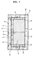
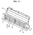
- FIG. 13 illustrates a perspective view of an inside of an outlet unit in accordance with a preferred embodiment of the present invention
- FIG. 14 illustrates a perspective view showing an electric cable placing portion of an outlet unit in accordance with a preferred embodiment of the present invention
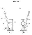
- FIG. 15 illustrates a side view of an outlet unit in accordance with a preferred embodiment of the present invention
- FIG. 16 illustrates an operation diagram showing an operation process of an outlet unit in accordance with a preferred embodiment of the present invention.
- the outlet unit 40 includes a body 42 mounted on the air outlet 16 in the base 12, a vane 44 on the body 42 for opening/closing an air outlet 41, a motor 45 for driving the vane 44, and a safety net 46 on the air outlet 41 of the body 42.
- the body 42 is mounted at the air outlet 16 of the base 12, and put close to the rib 12b and fastened.
- the body 42 of the outlet unit 40 is mounted to the air outlet 16 of the base 12, and the body 42 has an air outlet 41 therein so as to be in communication with the inside of the cabinet 10.
- the body 42 is mounted to the vane 44 for opening/closing the air outlet 41, and the vane 44 is rotatably hinged on the body 42.
- the vane 44 has hinges 44a at opposite ends each placed through a hinge hole 42a in the body 42 from an inside of the body 42, such that the vane 44 is rotatable around the hinges 44a in the hinge holes 42a.
- the hinge 44a of the vane 44 is rotatably positioned on an inside of the body 42 so that the air outlet 41 of the body 42 is opened as an inner edge 44c of the vane 44 moves into the body 42.
- a stopper 47 mounted on an inside of the body 42 having the air outlet 41 formed therein, there is a stopper 47 for preventing the vane 44 from rotating greater than a predetermined angle, by holding the inner edge 44c of the vane 44.
- the stopper 47 has a rib shape.
- a rib 43 in the middle of a length of the body 42 connected to an upper/and a lower walls for increasing rigidity of the body 42.
- the rib 43 also serves as a stopper 47.
- the motor 45 is at one side of the body 42 connected to the vane 44 for rotating the vane 44.
- the motor 45 is fixedly secured to a side of the body 42, and the vane 44 rotates as the hinge 44a connected to a motor shaft rotates.
- a safety net 46 mounted on the inside of the body 42, there is a safety net 46, for preventing a user's hand or foreign matters from entering therein.
- the safety net 46 is constructed of metal or plastic rods 46a and 46b crossed with one another, with ends thereof placed in holes 42c in the body 42, respectively.
- the safety net 46 is formed of steel, and more preferably, the rods 46a and 46b are thin and arranged with large spaces between the rods 46a and 46b for minimizing a resistance to the air being discharged.
- the safety net 46 is positioned on an inner side of the stopper 47 for preventing interference with the vane 44.
- the outlet unit 40 has an electric cable placing space for placing an electric cable 49 therein, which is a groove 40a in a bottom of the body 42.
- the electric cable 49 is placed between the body of the outlet unit 40 and the base 12 (see FIG. 15) such that the electric cable 49 is not exposed to the inside of the cabinet 10 where the air flows, and the electric cable 49 is placed in the groove 40a in the body 42.
- the groove 40a is extended along a length of the body 42, and the electric cable 49 is placed in the groove 40a held thereby.
- the body 42 has rib 48 for preventing the electric cable 49 from falling off the groove 40a.
- the rib 48 is extended from the body to a lower side of the body 42, and an end 48a of the rib 48 is in contact with the base 12, such that the contact between the rib 48 and the base 12 covers the electric cable in a state the electric cable is held in the body 42.
- the groove 40a in the body 42 has a sectional area smaller than a thickness of the electric cable 49 for firm placement of the electric cable 49 in the groove 40a.
- the electric cable 49 has connectors 49a and 49b at both ends, which are connected to the motor 45 and the outfit unit 150 (see FIG. 1), respectively.
- FIGS. 1 to 6 A process for assembling the picture frame panel in accordance with the present invention will be described in more detail with reference to FIGS. 1 to 6.
- the transparent plate 35 is seated on the outer edge 33 of the deco-frame 34 which is bent forward to assemble the transparent plate 35 and the deco-frame 34.
- the members 36a, 36b, 36c, and 36d of the deco 36 are inserted on four edges of the transparent plate 35 and the deco-frame 34 assemble thus respectively, such that the members 36a, 36b, 36c, and 36d of the deco 36 hold the transparent plate 35 and the deco-frame 34 at a time.
- a fastening member 39 is fastened to the hole 37c in the rear of the deco 36, and the fastening member 39 is passed through the deco 36, and inserted in the boss 34b' on the deco-frame 34, to press the deco-frame 34 onto the transparent plate 35.
- the transparent plate 35 supported on the front blade 37a of the deco 36 is secured to the deco 36 by the fastening of the fastening member 39.
- the transparent plate 35 secured by the pressing of the deco-frame 34 wherein, since the transparent plate 35 is pressed uniformly over a contact area with the deco-frame, the fastening force is uniform, and since applied force through the fastening member 39 is not concentrated, deformation or breakage of the transparent plate 35 is prevented.
- the picture frame panel 30 has an advantage in that the deco-frame 34/the transparent plate 35/the deco 36 are secured at a time.
- the orifice 13 is mounted fit to the fan 14.
- the outfit unit 150 is mounted over the orifice 13, the heat exchanger 50 is seated on the drain pan 100, the drain pan 100 is fastened to the cabinet 10, and the heat exchanger 50 is secured to a center of the orifice 13.
- the outlet units 40 are mounted to the air outlets 16 in the cabinet 10 respectively, and the front panel 20 is mounted on the cabinet 10.
- an upper portion of the front panel 20 is mounted on the cabinet 10, wherein the cover portion 27 of the front panel 20 is mounted to surround the rim 17 of the cabinet 10, and the hooks 27a on the inside surface of the cover portion 27 is inserted and held at the eyes 17a in the rim 17.
- the service cover 24 is mounted.
- the hook 24c on the back side of the service cover 24 is pushed into the hole 100c in the drain pan 100, to fastened the service cover 24, and a fastening member 109 is fastened thereto, for putting the service cover 24 and the drain pan 100 together, rigidly.
- cover portion 27 on the service cover 24 also surrounds and holds the rim 17.
- the front panel 20 is not removed entirely, but only the service cover 24 is removed, for connection of the connection pipe 52 of the heat exchanger 50 and the terminal box 155.
- connection pipe 52 is mounted on a left side or a right side of the heat exchanger 50, and one of the left/right pipe cover 11 is removed, to connect the connection pipe 52 to the pipe (not shown) connected to the indoor unit.
- electric cables are connected to the terminal block 155 exposed at the time of connection of the pipe.
- the safety net 46 is mounted to the body 42 by bending the safety net 46 slightly to place the rods 46a and 46b in the holes 42c in the body 42.
- the safety net 46 is formed of metal, the safety returns to an original state by elasticity after the mounting.
- the vane 44 is mounted to the body 42.
- the vane 44 is bent slightly, to place the hinge 44a on the other side of the vane 44 in rest of the hinge holes 42a.
- the motor 45 is connected to the hinge 44a placed in the body 42, and the motor 45 is fixedly secured to the body 42.
- the motor 45 may be connected to the hinge 44a directly, preferably, the motor 45 is connected to the hinge 44a through gears which is a power transmission mechanism.
- the connector of the electric cable 49 is connected to the motor 45, and the electric cable 49 is placed in the groove 40a on the bottom of the body, forcibly.
- the electric cable 49 is placed in along the groove 40a in the body 42 forcibly, and the electric cable is in contact with the rib 48 on the bottom of body 42, preventing the electric cable from falling off the body 42.
- the connector 49b on the other side is connected to the outfits 150.
- the assembled outlet unit 40 is mounted to air outlet 16 portion of the base 12, to make an inside and an outside of the cabinet 10 in communication through the air outlet 41 in the outlet unit 40.
- control unit rotates the vane 44 such that the air outlet 41 in the body 42 is closed, to bring the body 42 into close contact with the air outlet 41 in the body 42.
- control unit applies power to the motor 45, to rotate the hinge 44a of the vane 44 by a predetermined angle.
- the inner edge 44c of the vane 44 rotates inward into the air outlet 41, and the outer edge 44b moves away from the body 42, thereby opening the air outlet 41.
- An opening angle of the vane 44 is controlled by the motor 45, until the vane 44 is stopped at the stopper 47 on the body 42, to limit a maximum rotation angle of the vane 44.
- the safety net 46 of thin rods 46a and 46b on the body 42 not only minimizes a resistance between the air being discharged and the safety net 46, and blocks entrance of foreign matters or a user's hand into the cabinet 10.
- the indoor unit of an air conditioner of the present invention has the following advantages.
- the outlet unit can minimizes a resistance to the air as the safety net on the outlet is constructed of metal rods, and permits to block entrance of foreign matters and user's hand into the cabinet owing to the safety net and to maintain a maximum opening angle of the vane during operation of the air conditioner owing to the stopper on a body of the outlet unit.
- the placing of the electric cables in a groove in the outlet unit isolated from an air flowing space permits to prevent the electric cable from being in contact with the air during operation of the indoor unit, and reduces a flow resistance of air blowing.
- the electric cable placing space in the outlet unit preventing exposure of the electric cable permits to minimize interference during service, and prevent the electric cable from falling off because the electric cable placing space is between the base of the cabinet and the body of the outlet unit.
- the outlet unit minimizes a resistance to the air being discharged owing to the safety net constructed of metal rods, and since the fastening member to the deco passes through the deco to apply a pressure toward the transparent plate, the transparent plate, the deco-frame, and the deco are held together, at a time.
Abstract
Description
- The present invention relates to an indoor unit of an air conditioner, and more particularly, to an indoor unit of an air conditioner, in which a safety net at an outlet is formed of metal wire, and electric cables are laid on a groove in an outlet unit isolated from a space air is to be blown thereto.
- In general, the air conditioner, serving as a room heater, a room cooler, or an air purifier for cooling/heating a room, or purifying room air, provides human being a better room environment. Recently, an air conditioner has been developed, which is provided with a turbo-fan to minimize a thickness of a cabinet thereof to permit the air conditioner to be mounted on a wall of the room like a picture frame.
- FIG. 17 illustrates an exploded perspective view of a related art air conditioner.
- Referring to FIG. 17, the related art air conditioner is provided with a thin rectangular cabinet 1 with an opened front, a
fan 2 in the cabinet 1, a heat exchanger 3 in front of thefan 2, a front panel 4 with an air inlet 4a in front of the heat exchanger 3, an orifice 5 which is an air outlet between the cabinet 1 and the front panel 4, and a front grill 6 rotatably mounted in front of the front panel 4, for opening/closing the air inlet 4a. - The
fan 2 is provided with aturbo fan 2a and a motor 2b for rotating theturbo fan 2a, not only for minimizing thickness of the cabinet 1, but also for discharging air drawn through the air inlet 4a in a circumferential direction. - The orifice 5, between the heat exchanger 3 and the
fan 2, guides the air from the air inlet 4a to thefan 2. - In the meantime, mounted between the front panel 4 and the orifice 5, there is a filter 7 for filtering air from the air inlet 4a, and mounted above the orifice 5, there is a control box 8 which is a control unit.
- Mounted on the cabinet 1, there are outlet units 9 for guiding a direction of air blow at the time of air discharge from an inside of the cabinet 1.
- The outlet unit 9 has an air outlet on an inner side with a plurality of
grills 9a for guiding an air blow direction, and a motor (not shown) for operating vanes 9b. - However, the related art indoor unit of an air conditioner has the following problems in actual application.
- First, the plurality of
grills 9a at the outlet unit 9 reduces a flow speed of air being discharged. - Second, the electric cable connected to a motor mounted to the outlet unit 9, which is exposed to an inside of the cabinet 1, impedes service in assembly and mounting of the indoor unit.
- It would be desirable to provide an indoor unit of an air conditioner having wires laid on the outlet unit such that air speed reduction of air being discharged becomes the minimum.
- It would also be desirable to provide an indoor unit of an air conditioner having a mesh type wire detachably laid on the outlet unit.
- Additionally, it would also be desirable to provide an indoor unit of an air conditioner having a stopper for preventing vanes from being opened excessively.
- It would also be desirable to provide an indoor unit of an air conditioner having an electric cable placing space in the outlet unit for placing the electric cable therein.
- Accordingly, the invention provides an indoor unit of an air conditioner that includes a cabinet, and an outlet unit mounted to the cabinet for guiding air being discharged from an inside, wherein the outlet unit includes a body mounted to the cabinet, the body having an air outlet, a vane mounted to the body for opening/closing the air outlet, and a safety net detachably mounted to the air outlet of the body.
- Preferably, the safety net is forcibly placed in the body, formed of steel, and constructed of rods crossed with one another.
- The body has holes and ends of the rods are placed in the holes in the body respectively, and the body includes a stopper projected toward an inside of the air outlet for limiting movement of the vane.
- In another aspect of the present invention, an indoor unit of an air conditioner includes a cabinet, and an outlet unit mounted to the cabinet for guiding air being discharged from an inside, wherein the outlet unit includes a body mounted to the cabinet, the body having an air outlet, a vane mounted to the body for opening/closing the air outlet, and a stopper projected from the body toward an inside of the air outlet for limiting movement of the vane.
- The stopper has a rib shape, the body is provided with a safety net detachably mounted to the air outlet, and the safety net is positioned on an inner side of the stopper.
- The body includes a rib in the middle of a length of the body connected to upper/lower walls thereof, and the rib is projected to an inner side of the air outlet for limiting movement of the vane.
- The vane has an inner edge which is moved toward an inner side of the body to open the air outlet.
- In another aspect of the present invention, an indoor unit of an air conditioner includes a cabinet, and an outlet unit mounted to the cabinet for guiding air being discharged from an inside, wherein the outlet unit includes a body mounted to the cabinet, the body having an air outlet, and an electric cable placing space in the body.
- The indoor unit further includes a vane mounted to the body for opening/closing the air outlet, and the electric cable placing space is positioned between the cabinet and the body for isolating the electric cable placing space from an air flowing space.
- The electric cable placing space is a groove in the body, forcibly inserted in the groove, or secured to the groove held by the groove.
- The body has a rib extended in the groove for preventing the electric cable from falling off the groove, and the rib has an end in contact with the cabinet for closing the electric cable placing space.
- The indoor unit has outfit, and the outlet unit includes a vane mounted to the body for opening/closing the air outlet, and driving means for driving the vane, wherein the electric cable placing space has a cable placed therein for connecting the outfit to the driving means.
- The indoor unit of an air conditioner of the present invention minimizes a resistance to the air being discharged owing to a safety net of metal rods on an air outlet, and prevents foreign matters or a user's hand from entering into the cabinet owing to the safety net, the electric cable from being in contact with flowing air during operation of the indoor unit to reduce a flow resistance of air.
- The accompanying drawings, which are included to provide a further understanding of the invention, illustrate embodiments of the invention and together with the description serve to explain the principle of the invention.
- In the drawings:
- FIG. 1 illustrates an exploded perspective view of an indoor unit of an air conditioner in accordance with a preferred embodiment of the present invention.
- FIG. 2 illustrates an exploded perspective view of an inside of an indoor unit of an air conditioner in accordance with a preferred embodiment of the present invention.
- FIG. 3 illustrates an exploded perspective view of a picture frame panel of an indoor unit in accordance with a preferred embodiment of the present invention.
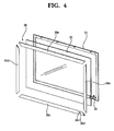
- FIG. 4 illustrates an exploded perspective view of a deco-frame of a picture frame panel of the present invention.
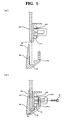
- FIG. 5 illustrates sections showing the steps of a process for assembling a picture frame panel in accordance with a preferred embodiment of the present invention.
- FIG. 6 illustrates a perspective view of a deco-frame with fastening portions in accordance with a preferred embodiment of the present invention.
- FIG. 7 illustrates a front view of a front panel in accordance with a preferred embodiment of the present invention.
- FIG. 8 illustrates a front view of a front panel in accordance with a preferred embodiment of the present invention, having a service cover removed therefrom.
- FIG. 9 illustrates an exploded perspective view of a cabinet and a front panel in accordance with a preferred embodiment of the present invention.
- FIG. 10 illustrates a perspective view a cabinet and a front panel assembled together in accordance with a preferred embodiment of the present invention.
- FIG. 11 illustrates a perspective view of a service cover and a drain pan in accordance with a preferred embodiment of the present invention.
- FIG. 12 illustrates a perspective view of an exterior of an outlet unit in accordance with a preferred embodiment of the present invention.
- FIG. 13 illustrates a perspective view of an inside of an outlet unit in accordance with a preferred embodiment of the present invention.
- FIG. 14 illustrates a perspective view showing an electric cable placing portion of an outlet unit in accordance with a preferred embodiment of the present invention.
- FIG. 15 illustrates a side view of an outlet unit in accordance with a preferred embodiment of the present invention.
- FIG. 16 illustrates an operation diagram showing an operation process of an outlet unit in accordance with a preferred embodiment of the present invention.
- FIG. 17 illustrates an exploded perspective view of a related art air conditioner.
- Reference will now be made in detail to the preferred embodiments of the present invention, examples of which are illustrated in the accompanying drawings. Wherever possible, the same reference numbers will be used throughout the drawings to refer to the same or like parts.
- An indoor unit of an air conditioner in accordance with a preferred embodiment of the present invention will be described.
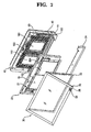
- FIGS. 1 and 2 illustrate exploded perspective views each showing an indoor unit of an air conditioner in accordance with a preferred embodiment of the present invention, FIG. 3 illustrates an exploded perspective view of a picture frame panel in accordance with a preferred embodiment of the present invention, FIG. 4 illustrates an exploded perspective view of a deco-frame of a picture frame panel of the present invention, FIG. 5 illustrates sections showing the steps of a process for assembling a picture frame panel in accordance with a preferred embodiment of the present invention, and FIG. 6 illustrates a perspective view of a deco-frame with fastening portions in accordance with a preferred embodiment of the present invention.
- Referring to FIGS. 1 or 2, the air conditioner in accordance with a preferred embodiment of the present invention includes a
cabinet 10 forming an exterior of the indoor unit, afront panel 20 mounted to a front of thecabinet 10, and apicture frame panel 30 mounted on thefront panel 20 spaced from thefront panel 20. - The
front panel 20 has acentral air inlet 15, and is fastened to thecabinet 10. - The
cabinet 10 has at least oneair outlet 16 for discharge of air. - The
picture frame panel 30 is mounted in front of thefront panel 20, spaced a predetermined distance from thefront panel 20 to form a gap through which air moves toward theair inlet 15. - In the meantime, the indoor unit includes a
base 12 to be mounted on a wall of a room, afan 14 on thebase 12 for drawing/discharging room air, and anorifice 13 for guiding air from theair inlet 15 to thefan 14. - The
fan 14 between thebase 12 and theorifice 13 guides the air from theair inlet 15 to theair outlet 16 entirely. - Particularly, the
fan 14 is a centrifugal fan for discharging air from theorifice 13 in a circumferential direction. - On opposite sides of the
fan 14, i.e., in opposite sides of thebase 12, there are theair outlets 16 for guiding air from thefan 14 to an outside of thecabinet 10. Each of theair outlets 16 has anoutlet unit 40 mounted thereon for opening/closing theair outlet 16. - The
air outlet 16 on an underside of the base 12 also has theoutlet unit 40 mounted thereon for guiding outlet air into the room opened/closed by the control unit of the indoor unit. - The
base 12 is fixedly secured to the wall of the room with a bracket on a back side. - Mounted over the
fan 14, i.e., at an upper portion of thebase 12, there is anair guide 18 for guiding the air from thefan 14 to theair outlets 16 on both sides of thebase 12. - In the meantime, mounted over the
orifice 13, there is anoutfit unit 150 of the control unit of the air conditioner. - In front of the
orifice 13, there is aheat exchanger 50 for making heat exchange with room air for cooling/heating the room air, and under theheat exchanger 50, there is adrain pan 100 for holding and draining condensed water formed at theheat exchanger 50. - The
heat exchanger 50 is secured to thefront panel 20 or theorifice 13, and has aconnection pipe 52 at one side for connection to a refrigerant pipe line (not shown) lead from an outside of the indoor unit. - Particularly, the
heat exchanger 50 has aplasma filter 160 on a front. - The
front panel 20 in front of theheat exchanger 50 is fastened to thebase 12. The fastening of thefront panel 20 to the base 12 forms theair outlet 16 on which theoutlet unit 40 is mounted. - The
cabinet 10 has pipe covers 11 mounted on corners to form a portion of an exterior of the indoor unit as the pipe covers 11 are mounted to corners of thebase 12. - The pipe covers 11 are mounted to a plurality of corners of the four corners of the
cabinet 10, through which the external refrigerant pipe line is lead into thecabinet 10. - In the meantime, referring to FIGS. 2 to 6, the
picture frame panel 30 includes apicture frame base 32, and a picture frame assembly rotatably hinged on thepicture frame base 32. - The picture frame assembly includes a deco-
frame 34 hinged on thepicture frame base 32, atransparent plate 35 placed in the deco-frame 34, adeco 36 for surrounding and holding the deco-frame 34 and thetransparent plate 35 at a time, and adisplay window 38 in the deco-frame 34. - The
transparent plate 35 is formed of transparent acryl, or glass, and positioned on a front of thepicture frame base 32 for exposing a picture or a photograph attached to thepicture frame base 32. - The deco-
frame 34 is mounted on a periphery of thetransparent plate 35 for securing thetransparent plate 35. - Referring to FIG. 4 or 6, the deco-
frame 34 includes fourmembers transparent plate 35, each of which are assembled together before mounting. - Accordingly, one
member 34a of the deco-frame 34 has ahole 34a' and theother member 34b to be coupled thereto has aboss 34b' to be placed in thehole 34a'. A fastening member (not shown) is fastened to theboss 34b' after thedeco 36 is assembled, to put the deco-frame 34 close to thedeco 36. - Together with this, the
members frame 34 haveouter edges 33 bent forward for surrounding an edge of thetransparent plate 35. - On an upper side of a back side of the deco-
frame 34, there areprojections 31 toward thepicture frame base 32, each with ahinge hole 31a for hinge connection to thepicture frame base 32. - The
hinge hole 31a is extended in a lateral direction at an upper side of the deco-frame 34 so that the picture frame assembly can turn around a top edge. - The
projection 31 connects thepicture frame base 32 to the picture frame assembly with a hinge as the projection is placed in a slot (not shown) in thepicture frame base 32 and a pin (not shown) is passed through the slot and theprojection 31. - On a lower side of the deco-
frame 34, there is thedisplay window 38 connected to theoutfit unit 150 for displaying a signal. - The
display window 38 between a lower side member and aright side member 34b of the deco-frame 34 is mounted at a lower side of a right side of the drawing, and thelower member 36c of thedeco 36 has ahole 36c' for exposing thedisplay window 38. - Though the embodiment shows the
display window 38 as a device for turning on an LED or the like, different from this, thedisplay window 38 may be a flat display unit, such as an LCD. - The
display window 38 displays an operation state of the indoor unit, or an environment of the room, or the like. - In the meantime, the
deco 36, for surrounding and holding edges both of the deco-frame 34 and thetransparent plate 35 at a time, has a '⊂' section with one opened side facing the transparent window. - The
deco 36 has fourmembers transparent plate 35 at a time. - In grooves 37 in the
members frame 34 and thetransparent plate 35 are placed. - Particularly, a
front side blade 37a of thedeco 36 is made to be in close contact with thetransparent plate 35, and arear side blade 37b of thedeco 36 is made to be in close contact with the deco-frame 34. - The
rear side blade 37b of thedeco 36 is formed long enough to cover thehole 34a'/boss 34b' portions to which themembers frame 34 are engaged. - The
rear side blade 37b of thedeco 36 has ahole 37c for placing afastening member 39 therein, and thefastening member 39 placed through thehole 37c of thedeco 36 is placed in theboss 34b' of the deco-frame 34 after thefastening member 39 is placed through thehole 37c. As an inserted depth of thefastening member 39 becomes the deeper, thefastening member 39 presses the deco-frame 34 onto thetransparent plate 35. - The
hole 37c in thedeco 36 has a thread formed thereon for fastening with thefastening member 39, and an end of thefastening member 39 pushes the deco-frame 34 toward thetransparent plate 35. - The
front side blade 37a of thedeco 36 is long enough to make the deco-frame 34 invisible through thetransparent plate 35, thehole 36c' in thedeco 36 matches with thedisplay window 38. - Assembly of the
picture frame panel 30 of the present invention is efficient because thefastening member 39 presses the deco-frame 34 onto thetransparent plate 35 at the time thefastening member 39 is fastened, and fastening of thedeco 36 and the deco-plate 34 is made at a time. - FIG. 7 illustrates a front view of a front panel in accordance with a preferred embodiment of the present invention, FIG. 8 illustrates a front view of a front panel in accordance with a preferred embodiment of the present invention, having a service cover removed therefrom, FIG. 9 illustrates an exploded perspective view of a cabinet and a front panel in accordance with a preferred embodiment of the present invention, and FIG. 10 illustrates a perspective view a cabinet and a front panel assembled together in accordance with a preferred embodiment of the present invention.
- Referring to FIGS. 7 to 10, the
front panel 20 includes theair inlet 15 at a center, and aservice cover 24 under theair inlet 15 for covering a portion of an inside of thecabinet 10. Theservice cover 24 is a portion of an exterior of thefront panel 20. - The
service cover 24 is detachably mounted on thefront panel 20 with ahook 27a and ahole 17a. Theservice cover 24 and thedrain pan 100 are fastened together and is fastened to thefront panel 20 with a bolt (not shown) or a screw (not shown). - Particularly, the
service cover 24 is fastened to thefront panel 20, such that oneend 24a thereof is positioned in front of alower connection pipe 52 of the heat exchanger for covering theconnection pipe 52, and the other end covers aterminal box 155 for supplying power to theoutfit unit 150. - The
terminal box 155 is separate from theoutfit unit 150, and connected with cable for supplying power. - Particularly, the
terminal box 155, covered with theservice cover 14, can be repaired only after removing theservice cover 24 instead of removing thefront panel 20 entirely, in a case repair of theterminal box 155 is required. - Moreover, at the time of installation of the indoor unit, after removing, not the
front panel 20 entirely, but only the service cover, the refrigerant pipeline is connected to the heat exchanger, and the cable is connected to theterminal box 155, thereby simplifying the installation of the indoor unit. - Referring to FIG. 9 or 10, the
cover portion 27 of thefront panel 20 is bent backward to cover a front side edge of thecabinet 10. - The
cabinet 10 has arim 17 at a front side edge covered with thefront panel 20, such that therim 17 is inserted in thecover portion 17. - Particularly, in the embodiment, the
hook 27a on an inside surface of thecover portion 27 of thefront panel 20 and thehole 17a on therim 17 of thecabinet 10 are engaged at the time thefront panel 20 is mounted on thecabinet 10, such that thefront panel 20 covers therim 17 of thecabinet 10. - Thus, the front side edge of the
cabinet 10 is covered with, and secured to thecover portion 27 which is a rear side edge of thefront panel 20, such that a line of coupling of thecabinet 10 and thefront panel 20 are not shown on the exterior of the indoor unit. - That is, the
cover portion 27 is mounted to cover therim 17 entirely, not to expose therim 17, but to expose thecover portion 27 on the exterior of the indoor unit. - Accordingly, since the coupling line of the
cabinet 10 and thefront panel 20 is not exposed, the indoor unit has a simple exterior, to prevent the coupling line from becoming dirt with dust or impurity. - Moreover, since the
front panel 20 covers an outside of thecabinet 10, the indoor unit of the present invention has a flatness improved at the coupling portion of thefront panel 20 and thecabinet 10. - That is, if the coupling line is exposed to the exterior, the exterior appears elegant only when abutting surfaces of the
front panel 20 and thecabinet 10 are continuous, if not, the flatness of the exterior appears poor. However, in the present invention, since thefront panel 20 covers an outside of thecabinet 10, the flatness or a coupling state of the coupling line is not required to take into account, which increases freedoms of design. - In the meantime, referring to FIG. 1 or 2, the
front panel 20 has a front grill 21 (see FIG. 1) on the front thereof, and theair inlet 15 has afilter 60 mounted thereon for filtering air flowing toward theorifice 13. - The
front grill 21 is extended from thefront panel 20 toward a center side of theair inlet 15 limited to a portion of a circumference of theair inlet 15. - The
front grill 21 is projected forward from thefront panel 20 toward thepicture frame panel 30. - The
filter 60 is detachably mounted on thefront panel 20. In this instance, thefilter 60 has a lower edge inserted in aslot 25 in thefront panel 20, and an upper edge inserted in a holdingslot 23. - The
filter 60 is projected forward by a predetermined distance in conformity with thefront grill 21 projected toward thepicture frame panel 30. In the embodiment, thefilter 60 has a circumference of thefilter 60 attached to a circumference of theair inlet 15, and a central portion only bulged forward. - The central bulge of the
filter 60 suppresses thefilter 60 from being in contact with theheat exchanger 50 in a back side of thefilter 60, and provides thefilter 60 with a greater area compared to a planar filter. - FIG. 11 illustrates a perspective view of a service cover and a drain pan in accordance with a preferred embodiment of the present invention.
- Referring to FIG. 11, the
service cover 24 of the present invention covers a lower outside circumference of thecabinet 10 fastened, and secured to thedrain pan 100. - The
service cover 24 has hooks 24c each projected from the back side toward thedrain pan 100, and thedrain pan 100 hasslots 100c for placing the hooks 24c therein respectively. Moreover, theservice cover 24 is fastened to thedrain pan 100 withfastening members 109 throughfastening holes 24d in theservice cover 24 andbosses 103 on thedrain pan 100. - The
drain pan 100 includes ahousing 102,ribs 104 in thehousing 102, and adrain pipe 106 for draining condensed water from thehousing 102 to an outside of the indoor unit. - The
housing 102 is a hexahedral box with an opened top. The heat exchanger 50 (see FIG. 1) is seated in thehousing 102. - Particularly, the
housing 102 has a top edge of afront wall 102a higher than a top edge of arear wall 102b for reducing resistance of air passing through theheat exchanger 50. - The
ribs 104 in thehousing 102 are vertical to support a bottom of theheat exchanger 50. - The
rib 104 is a thin plate extended in a lateral direction for lateral contact with the bottom of theheat exchanger 50 which is mounted in the lateral direction. - Particularly, the
ribs 104 are formed to guide the condensed water toward thedrain pipe 106. - The plurality of
ribs 104 are arranged in a zigzag form for smooth movement of the condensed water from thehousing 102 to thedrain pipe 106 at a side of theservice housing 102. - The
rib 104 has a height lower than the top edges of thefront wall 102a or therear wall 102b of thehousing 102, so that thefront wall 102a or therear wall 102b supports the front of rear of theheat exchanger 50. - The
drain pipe 106 passes through thehousing 102, and has an end on an outside of thehousing 102 with a condensed water hose (not shown) connected thereto for guiding the condensed water from thehousing 102 to an outside of the room. - FIG. 12 illustrates a perspective view of an exterior of an outlet unit in accordance with a preferred embodiment of the present invention, FIG. 13 illustrates a perspective view of an inside of an outlet unit in accordance with a preferred embodiment of the present invention, FIG. 14 illustrates a perspective view showing an electric cable placing portion of an outlet unit in accordance with a preferred embodiment of the present invention, FIG. 15 illustrates a side view of an outlet unit in accordance with a preferred embodiment of the present invention, and FIG. 16 illustrates an operation diagram showing an operation process of an outlet unit in accordance with a preferred embodiment of the present invention.
- Referring to FIG. 1 or 2 and 12 to 16, the
outlet unit 40 includes abody 42 mounted on theair outlet 16 in thebase 12, avane 44 on thebody 42 for opening/closing anair outlet 41, amotor 45 for driving thevane 44, and asafety net 46 on theair outlet 41 of thebody 42. - The
body 42 is mounted at theair outlet 16 of thebase 12, and put close to the rib 12b and fastened. - Accordingly, the
body 42 of theoutlet unit 40 is mounted to theair outlet 16 of thebase 12, and thebody 42 has anair outlet 41 therein so as to be in communication with the inside of thecabinet 10. - Along with this, the
body 42 is mounted to thevane 44 for opening/closing theair outlet 41, and thevane 44 is rotatably hinged on thebody 42. - Accordingly, the
vane 44 hashinges 44a at opposite ends each placed through ahinge hole 42a in thebody 42 from an inside of thebody 42, such that thevane 44 is rotatable around thehinges 44a in thehinge holes 42a. - The
hinge 44a of thevane 44 is rotatably positioned on an inside of thebody 42 so that theair outlet 41 of thebody 42 is opened as an inner edge 44c of thevane 44 moves into thebody 42. - Moreover, mounted on an inside of the
body 42 having theair outlet 41 formed therein, there is astopper 47 for preventing thevane 44 from rotating greater than a predetermined angle, by holding the inner edge 44c of thevane 44. - The
stopper 47 has a rib shape. - In the meantime, on an inside of the
body 42, there is a rib 43 in the middle of a length of thebody 42 connected to an upper/and a lower walls for increasing rigidity of thebody 42. The rib 43 also serves as astopper 47. - The
motor 45 is at one side of thebody 42 connected to thevane 44 for rotating thevane 44. - The
motor 45 is fixedly secured to a side of thebody 42, and thevane 44 rotates as thehinge 44a connected to a motor shaft rotates. - In the meantime, mounted on the inside of the
body 42, there is asafety net 46, for preventing a user's hand or foreign matters from entering therein. - The
safety net 46 is constructed of metal orplastic rods holes 42c in thebody 42, respectively. - Preferably, the
safety net 46 is formed of steel, and more preferably, therods rods - Along with this, the
safety net 46 is positioned on an inner side of thestopper 47 for preventing interference with thevane 44. - In the meantime, referring to FIGS. 12 to 15, the
outlet unit 40 has an electric cable placing space for placing anelectric cable 49 therein, which is agroove 40a in a bottom of thebody 42. - The
electric cable 49 is placed between the body of theoutlet unit 40 and the base 12 (see FIG. 15) such that theelectric cable 49 is not exposed to the inside of thecabinet 10 where the air flows, and theelectric cable 49 is placed in thegroove 40a in thebody 42. - The
groove 40a is extended along a length of thebody 42, and theelectric cable 49 is placed in thegroove 40a held thereby. Thebody 42 hasrib 48 for preventing theelectric cable 49 from falling off thegroove 40a. - Particularly, the
rib 48 is extended from the body to a lower side of thebody 42, and anend 48a of therib 48 is in contact with thebase 12, such that the contact between therib 48 and the base 12 covers the electric cable in a state the electric cable is held in thebody 42. - Preferably, the
groove 40a in thebody 42 has a sectional area smaller than a thickness of theelectric cable 49 for firm placement of theelectric cable 49 in thegroove 40a. - The
electric cable 49 hasconnectors motor 45 and the outfit unit 150 (see FIG. 1), respectively. - A process for assembling the picture frame panel in accordance with the present invention will be described in more detail with reference to FIGS. 1 to 6.
-
Members frame 34 are assembled together. - Then, the
transparent plate 35 is seated on theouter edge 33 of the deco-frame 34 which is bent forward to assemble thetransparent plate 35 and the deco-frame 34. - The
members deco 36 are inserted on four edges of thetransparent plate 35 and the deco-frame 34 assemble thus respectively, such that themembers deco 36 hold thetransparent plate 35 and the deco-frame 34 at a time. - A
fastening member 39 is fastened to thehole 37c in the rear of thedeco 36, and thefastening member 39 is passed through thedeco 36, and inserted in theboss 34b' on the deco-frame 34, to press the deco-frame 34 onto thetransparent plate 35. - Particularly, the
transparent plate 35 supported on thefront blade 37a of thedeco 36 is secured to thedeco 36 by the fastening of thefastening member 39. - Along with this, the
transparent plate 35 secured by the pressing of the deco-frame 34 wherein, since thetransparent plate 35 is pressed uniformly over a contact area with the deco-frame, the fastening force is uniform, and since applied force through thefastening member 39 is not concentrated, deformation or breakage of thetransparent plate 35 is prevented. - Moreover, the
picture frame panel 30 has an advantage in that the deco-frame 34/thetransparent plate 35/thedeco 36 are secured at a time. - A process for mounting the front panel in accordance with a preferred embodiment of the present invention will be described in more detail with reference to FIGS. 1, and 7 to 11.
- After mounting the
fan 14 and the air guides 18 on thecabinet 10, theorifice 13 is mounted fit to thefan 14. - The
outfit unit 150 is mounted over theorifice 13, theheat exchanger 50 is seated on thedrain pan 100, thedrain pan 100 is fastened to thecabinet 10, and theheat exchanger 50 is secured to a center of theorifice 13. - Then, the
outlet units 40 are mounted to theair outlets 16 in thecabinet 10 respectively, and thefront panel 20 is mounted on thecabinet 10. - At first, an upper portion of the
front panel 20 is mounted on thecabinet 10, wherein thecover portion 27 of thefront panel 20 is mounted to surround therim 17 of thecabinet 10, and thehooks 27a on the inside surface of thecover portion 27 is inserted and held at theeyes 17a in therim 17. - Next, after the upper portion of the
front panel 20 is mounted, theservice cover 24 is mounted. - After determining left/right sides of the
service cover 24, the hook 24c on the back side of theservice cover 24 is pushed into thehole 100c in thedrain pan 100, to fastened theservice cover 24, and afastening member 109 is fastened thereto, for putting theservice cover 24 and thedrain pan 100 together, rigidly. - In this instance, the
cover portion 27 on theservice cover 24 also surrounds and holds therim 17. - In the meantime, when the indoor unit is mounted, the
front panel 20 is not removed entirely, but only theservice cover 24 is removed, for connection of theconnection pipe 52 of theheat exchanger 50 and theterminal box 155. - That is, depending on a direction of mounting of the pipe, the
connection pipe 52 is mounted on a left side or a right side of theheat exchanger 50, and one of the left/right pipe cover 11 is removed, to connect theconnection pipe 52 to the pipe (not shown) connected to the indoor unit. - Moreover, electric cables are connected to the
terminal block 155 exposed at the time of connection of the pipe. - A process for mounting the outlet unit in accordance with a preferred embodiment of the present invention will be described with reference to FIGS. 12 to 15.
- At first, the
safety net 46 is mounted to thebody 42 by bending thesafety net 46 slightly to place therods holes 42c in thebody 42. - Since the
safety net 46 is formed of metal, the safety returns to an original state by elasticity after the mounting. - Then, the
vane 44 is mounted to thebody 42. - In this instance, after placing the
hinge 44a on one side of thevane 44 in one of thehinge holes 42a in thebody 42, thevane 44 is bent slightly, to place thehinge 44a on the other side of thevane 44 in rest of thehinge holes 42a. - After the
vane 44 is mounted, themotor 45 is connected to thehinge 44a placed in thebody 42, and themotor 45 is fixedly secured to thebody 42. - Though the
motor 45 may be connected to thehinge 44a directly, preferably, themotor 45 is connected to thehinge 44a through gears which is a power transmission mechanism. - Once the
motor 45 is secured, the connector of theelectric cable 49 is connected to themotor 45, and theelectric cable 49 is placed in thegroove 40a on the bottom of the body, forcibly. - The
electric cable 49 is placed in along thegroove 40a in thebody 42 forcibly, and the electric cable is in contact with therib 48 on the bottom ofbody 42, preventing the electric cable from falling off thebody 42. - Upon finishing forcible placement of the
electric cable 49 in thegroove 40a fully, theconnector 49b on the other side is connected to theoutfits 150. - In the meantime, upon finishing assembling of the
outlet unit 40, the assembledoutlet unit 40 is mounted toair outlet 16 portion of thebase 12, to make an inside and an outside of thecabinet 10 in communication through theair outlet 41 in theoutlet unit 40. - A process for operating the outlet unit of the present invention will be described with reference to FIG. 10.
- At first, if the air conditioner is not in operation, the control unit rotates the
vane 44 such that theair outlet 41 in thebody 42 is closed, to bring thebody 42 into close contact with theair outlet 41 in thebody 42. - If the air conditioner is in operation, the control unit applies power to the
motor 45, to rotate thehinge 44a of thevane 44 by a predetermined angle. - Following rotation of the
hinge 44a, the inner edge 44c of thevane 44 rotates inward into theair outlet 41, and theouter edge 44b moves away from thebody 42, thereby opening theair outlet 41. - An opening angle of the
vane 44 is controlled by themotor 45, until thevane 44 is stopped at thestopper 47 on thebody 42, to limit a maximum rotation angle of thevane 44. - Especially, if the inner edge 44c of the
vane 44 is brought into contact with thestopper 47 and supported thereon, shaking of thevane 44 is reduced at the time the air is blown through theair outlet 41. - The
safety net 46 ofthin rods body 42, not only minimizes a resistance between the air being discharged and thesafety net 46, and blocks entrance of foreign matters or a user's hand into thecabinet 10. - It will be apparent to those skilled in the art that various modifications and variations can be made in the present invention without departing from the scope of the invention. Thus, it is intended that the present invention cover the modifications and variations of this invention provided they come within the scope of the appended claims and their equivalents.
- As has been described, the indoor unit of an air conditioner of the present invention has the following advantages.
- First, the outlet unit can minimizes a resistance to the air as the safety net on the outlet is constructed of metal rods, and permits to block entrance of foreign matters and user's hand into the cabinet owing to the safety net and to maintain a maximum opening angle of the vane during operation of the air conditioner owing to the stopper on a body of the outlet unit.
- Second, since the vane of the outlet unit is supported on the stopper on the body during operation of the air conditioner, shaking of the vane taking place during operation of the air conditioner is minimized, and the outlet unit has low noise as the resistance to the air with the safety net is minimized because the safety net is constructed of thin rods.
- Third, the placing of the electric cables in a groove in the outlet unit isolated from an air flowing space permits to prevent the electric cable from being in contact with the air during operation of the indoor unit, and reduces a flow resistance of air blowing.
- Fourth, the electric cable placing space in the outlet unit preventing exposure of the electric cable permits to minimize interference during service, and prevent the electric cable from falling off because the electric cable placing space is between the base of the cabinet and the body of the outlet unit.
- Fifth, since the electric cable is forcibly inserted in the groove in the body of the outlet unit, falling off of the electric cable is suppressed once the electric cable is placed therein, and since the groove of the body is constructed of the rib, and the rib is in close contact with the base, movement of the electric cable is limited by the rib even if the electric cable falls off the groove.
- Sixth, the safety net on the outlet blocks entrance of foreign matters or a user's hand into the cabinet, the outlet unit minimizes a resistance to the air being discharged owing to the safety net constructed of metal rods, and since the fastening member to the deco passes through the deco to apply a pressure toward the transparent plate, the transparent plate, the deco-frame, and the deco are held together, at a time.
Claims (21)
- An indoor unit of an air conditioner comprising:a cabinet; andan outlet unit mounted to the cabinet for guiding air being discharged from an inside,wherein the outlet unit includes;a body mounted to the cabinet, the body having an air outlet,a vane mounted to the body for opening/closing the air outlet, anda safety net detachably mounted to the air outlet of the body.
- The indoor unit as claimed in claim 1, wherein the safety net is forcibly placed in the body.
- The indoor unit as claimed in claim 1 or 2, wherein the safety net is formed of steel.
- The indoor unit as claimed in claim 1 or 2, wherein the safety net is constructed of rods crossed with one another.
- The indoor unit as claimed in claim 4, wherein the body has holes and ends of the rods are placed in the holes in the body, respectively.
- The indoor unit as claimed in claim 1 or 2, wherein the body includes a stopper projected toward an inside of the air outlet for limiting movement of the vane.
- An indoor unit of an air conditioner comprising:a cabinet; andan outlet unit mounted to the cabinet for guiding air being discharged from an inside,wherein the outlet unit includes;a body mounted to the cabinet, the body having an air outlet,a vane mounted to the body for opening/closing the air outlet, anda stopper projected from the body toward an inside of the air outlet for limiting movement of the vane.
- The indoor unit as claimed in claim 7, wherein the stopper has a rib shape.
- The indoor unit as claimed in claim 7 or 8, wherein the body is provided with a safety net detachably mounted to the air outlet, and the safety net is positioned on an inner side of the stopper.
- The indoor unit as claimed in claim 7, wherein the body includes a rib in the middle of a length of the body connected to upper/lower walls thereof.
- The indoor unit as claimed in claim 10, wherein the rib is projected to an inner side of the air outlet for limiting movement of the vane.
- The indoor unit as claimed in claim 7 or 11, wherein the vane has an inner edge which is moved toward an inner side of the body to open the air outlet.
- An indoor unit of an air conditioner comprising:a cabinet; andan outlet unit mounted to the cabinet for guiding air being discharged from an inside,wherein the outlet unit includes;a body mounted to the cabinet, the body having an air outlet, andan electric cable placing space in the body.
- The indoor unit as claimed in claim 13, further comprising a vane mounted to the body for opening/closing the air outlet.
- The indoor unit as claimed in claim 13 or 14, wherein the electric cable placing space is positioned between the cabinet and the body for isolating the electric cable placing space from an air flowing space.
- The indoor unit as claimed in claim 13 and 14, wherein the electric cable placing space is a groove in the body.
- The indoor unit as claimed in claim 16, wherein the electric cable is forcibly inserted in the groove.
- The indoor unit as claimed in claim 16, wherein the electric cable is secured to the groove held by the groove.
- The indoor unit as claimed in claim 16, wherein the body has a rib extended in the groove for preventing the electric cable from falling off the groove.
- The indoor unit as claimed in claim 19, wherein the rib has an end in contact with the cabinet for closing the electric cable placing space.
- The indoor unit as claimed in claim 13, wherein the indoor unit has outfit, and the outlet unit includes;
a vane mounted to the body for opening/closing the air outlet, and
driving means for driving the vane,
wherein the electric cable placing space has a cable placed therein for connecting the outfit to the driving means.
Applications Claiming Priority (2)
| Application Number | Priority Date | Filing Date | Title |
|---|---|---|---|
| KR1020060011656A KR20070080387A (en) | 2006-02-07 | 2006-02-07 | Indoor unit of air conditioner |
| KR1020060011655A KR20070080386A (en) | 2006-02-07 | 2006-02-07 | Indoor unit of air conditioner |
Publications (3)
| Publication Number | Publication Date |
|---|---|
| EP1816404A2 true EP1816404A2 (en) | 2007-08-08 |
| EP1816404A3 EP1816404A3 (en) | 2012-02-01 |
| EP1816404B1 EP1816404B1 (en) | 2016-03-23 |
Family
ID=37969776
Family Applications (1)
| Application Number | Title | Priority Date | Filing Date |
|---|---|---|---|
| EP06256320.0A Not-in-force EP1816404B1 (en) | 2006-02-07 | 2006-12-12 | Indoor unit of air conditioner |
Country Status (3)
| Country | Link |
|---|---|
| EP (1) | EP1816404B1 (en) |
| ES (1) | ES2566727T3 (en) |
| WO (1) | WO2007091768A2 (en) |
Families Citing this family (1)
| Publication number | Priority date | Publication date | Assignee | Title |
|---|---|---|---|---|
| CN110296511B (en) * | 2019-07-09 | 2021-01-29 | 珠海格力电器股份有限公司 | Intelligent control method and system for finger protection net of air conditioner and storage medium |
Citations (1)
| Publication number | Priority date | Publication date | Assignee | Title |
|---|---|---|---|---|
| JP2004317051A (en) | 2003-04-17 | 2004-11-11 | Fujitsu General Ltd | Air conditioner |
Family Cites Families (19)
| Publication number | Priority date | Publication date | Assignee | Title |
|---|---|---|---|---|
| GB584678A (en) * | 1944-05-15 | 1947-01-21 | Victor Asarius Kennett | An improved controlling valve or register for air-ducts and the like |
| US4009648A (en) * | 1975-10-03 | 1977-03-01 | General Motors Corporation | Air conditioner air flow control mechanism |
| JPS5869334A (en) * | 1981-10-21 | 1983-04-25 | Mitsubishi Electric Corp | Air conditioner |
| DE9211142U1 (en) * | 1992-08-20 | 1992-12-17 | "Schako" Metallwarenfabrik Ferdinand Schad Kg Zweigniederlassung Kolbingen, 7201 Kolbingen, De | |
| KR0126751Y1 (en) * | 1994-08-11 | 1998-11-02 | 윤종용 | Wind direction control device |
| KR0119913Y1 (en) * | 1994-08-11 | 1998-07-15 | 김광호 | Air folw control device of air conditioner |
| JP2993412B2 (en) * | 1995-11-20 | 1999-12-20 | 三菱電機株式会社 | Air outlet and air conditioner provided with the air outlet |
| US5643081A (en) * | 1996-07-11 | 1997-07-01 | Klein; James A. | Vent screen and vent apparatus |
| JP3282616B2 (en) * | 1999-11-05 | 2002-05-20 | ダイキン工業株式会社 | Ceiling-mounted air conditioner |
| JP3624837B2 (en) * | 2001-02-01 | 2005-03-02 | ダイキン工業株式会社 | Indoor air conditioner |
| HUP0303237A3 (en) * | 2001-03-20 | 2004-06-28 | Aermec Spa | Air-distribution cap for a convector |
| KR100445467B1 (en) * | 2001-04-20 | 2004-08-21 | 주식회사 엘지이아이 | Indoor unit for air conditioner |
| MY130916A (en) * | 2001-06-19 | 2007-07-31 | Lg Electronics Inc | Air conditioner |
| JP3735592B2 (en) * | 2001-06-19 | 2006-01-18 | エルジー電子株式会社 | Air conditioner |
| JP4219231B2 (en) * | 2002-10-30 | 2009-02-04 | 三洋電機株式会社 | Air conditioner |
| US7204096B2 (en) * | 2002-10-31 | 2007-04-17 | Daikin Industries, Ltd. | Indoor apparatus for air conditioner |
| JP3841067B2 (en) * | 2003-06-25 | 2006-11-01 | ダイキン工業株式会社 | Air conditioner indoor unit electrical unit |
| JP3879712B2 (en) * | 2003-06-26 | 2007-02-14 | ダイキン工業株式会社 | Air conditioner |
| JP2005188814A (en) * | 2003-12-25 | 2005-07-14 | Toshiba Kyaria Kk | Indoor unit for air conditioner |
-
2006
- 2006-11-30 WO PCT/KR2006/005139 patent/WO2007091768A2/en active Application Filing
- 2006-12-12 ES ES06256320.0T patent/ES2566727T3/en active Active
- 2006-12-12 EP EP06256320.0A patent/EP1816404B1/en not_active Not-in-force
Patent Citations (1)
| Publication number | Priority date | Publication date | Assignee | Title |
|---|---|---|---|---|
| JP2004317051A (en) | 2003-04-17 | 2004-11-11 | Fujitsu General Ltd | Air conditioner |
Also Published As
| Publication number | Publication date |
|---|---|
| EP1816404A3 (en) | 2012-02-01 |
| WO2007091768A2 (en) | 2007-08-16 |
| EP1816404B1 (en) | 2016-03-23 |
| ES2566727T3 (en) | 2016-04-15 |
| WO2007091768A3 (en) | 2009-05-14 |
Similar Documents
| Publication | Publication Date | Title |
|---|---|---|
| EP1816406B1 (en) | Indoor unit of air conditioner | |
| EP1248048A2 (en) | Air conditioner | |
| US20120135674A1 (en) | Wall-mounted type air conditioner | |
| JP2005114346A (en) | Indoor unit for air conditioner | |
| WO2006075850A1 (en) | Air conditioner | |
| JP2005249373A (en) | Indoor unit for air-conditioner | |
| JP2005249374A (en) | Indoor unit for air-conditioner | |
| JP2005127696A (en) | Indoor unit for air conditioner | |
| EP1816407B1 (en) | Indoor unit of air conditioner | |
| KR101259806B1 (en) | Indoor unit of air conditioner | |
| KR101259805B1 (en) | Indoor unit of air conditioner | |
| EP1816404B1 (en) | Indoor unit of air conditioner | |
| EP1816403B1 (en) | Indoor unit of air conditioner | |
| KR20100052385A (en) | Indoor unit for air conditioning apparatus and assembling method thereof | |
| KR20070080387A (en) | Indoor unit of air conditioner | |
| KR20070080385A (en) | Indoor unit of air conditioner | |
| KR20070080272A (en) | Indoor unit of air conditioner | |
| CN101017013B (en) | Indoor unit of air conditioner | |
| EP1813876A2 (en) | Indoor unit of air conditioner | |
| KR20070080384A (en) | Indoor unit of air conditioner | |
| KR20070092524A (en) | Indoor unit of air conditioner | |
| KR101186324B1 (en) | Indoor unit of air conditioner | |
| KR101090480B1 (en) | Indoor unit of picture frame type air-conditioner | |
| KR20080027680A (en) | Indoor unit of air conditioner |
Legal Events
| Date | Code | Title | Description |
|---|---|---|---|
| PUAI | Public reference made under article 153(3) epc to a published international application that has entered the european phase |
Free format text: ORIGINAL CODE: 0009012 |
|
| AK | Designated contracting states |
Kind code of ref document: A2 Designated state(s): AT BE BG CH CY CZ DE DK EE ES FI FR GB GR HU IE IS IT LI LT LU LV MC NL PL PT RO SE SI SK TR |
|
| AX | Request for extension of the european patent |
Extension state: AL BA HR MK YU |
|
| PUAL | Search report despatched |
Free format text: ORIGINAL CODE: 0009013 |
|
| AK | Designated contracting states |
Kind code of ref document: A3 Designated state(s): AT BE BG CH CY CZ DE DK EE ES FI FR GB GR HU IE IS IT LI LT LU LV MC NL PL PT RO SE SI SK TR |
|
| AX | Request for extension of the european patent |
Extension state: AL BA HR MK RS |
|
| RIC1 | Information provided on ipc code assigned before grant |
Ipc: F24F 1/00 20110101AFI20111223BHEP |
|
| 17P | Request for examination filed |
Effective date: 20120801 |
|
| 17Q | First examination report despatched |
Effective date: 20120910 |
|
| AKX | Designation fees paid |
Designated state(s): AT BE BG CH CY CZ DE DK EE ES FI FR GB GR HU IE IS IT LI LT LU LV MC NL PL PT RO SE SI SK TR |
|
| GRAP | Despatch of communication of intention to grant a patent |
Free format text: ORIGINAL CODE: EPIDOSNIGR1 |
|
| RIC1 | Information provided on ipc code assigned before grant |
Ipc: F24F 13/20 20060101ALI20150409BHEP Ipc: F24F 1/00 20110101AFI20150409BHEP |
|
| INTG | Intention to grant announced |
Effective date: 20150508 |
|
| GRAP | Despatch of communication of intention to grant a patent |
Free format text: ORIGINAL CODE: EPIDOSNIGR1 |
|
| INTG | Intention to grant announced |
Effective date: 20151008 |
|
| GRAS | Grant fee paid |
Free format text: ORIGINAL CODE: EPIDOSNIGR3 |
|
| GRAA | (expected) grant |
Free format text: ORIGINAL CODE: 0009210 |
|
| AK | Designated contracting states |
Kind code of ref document: B1 Designated state(s): AT BE BG CH CY CZ DE DK EE ES FI FR GB GR HU IE IS IT LI LT LU LV MC NL PL PT RO SE SI SK TR |
|
| REG | Reference to a national code |
Ref country code: GB Ref legal event code: FG4D |
|
| REG | Reference to a national code |
Ref country code: CH Ref legal event code: EP |
|
| REG | Reference to a national code |
Ref country code: AT Ref legal event code: REF Ref document number: 783549 Country of ref document: AT Kind code of ref document: T Effective date: 20160415 Ref country code: ES Ref legal event code: FG2A Ref document number: 2566727 Country of ref document: ES Kind code of ref document: T3 Effective date: 20160415 |
|
| REG | Reference to a national code |
Ref country code: IE Ref legal event code: FG4D |
|
| REG | Reference to a national code |
Ref country code: DE Ref legal event code: R096 Ref document number: 602006048326 Country of ref document: DE |
|
| REG | Reference to a national code |
Ref country code: LT Ref legal event code: MG4D |
|
| REG | Reference to a national code |
Ref country code: NL Ref legal event code: MP Effective date: 20160323 |
|
| PG25 | Lapsed in a contracting state [announced via postgrant information from national office to epo] |
Ref country code: FI Free format text: LAPSE BECAUSE OF FAILURE TO SUBMIT A TRANSLATION OF THE DESCRIPTION OR TO PAY THE FEE WITHIN THE PRESCRIBED TIME-LIMIT Effective date: 20160323 Ref country code: GR Free format text: LAPSE BECAUSE OF FAILURE TO SUBMIT A TRANSLATION OF THE DESCRIPTION OR TO PAY THE FEE WITHIN THE PRESCRIBED TIME-LIMIT Effective date: 20160624 |
|
| REG | Reference to a national code |
Ref country code: AT Ref legal event code: MK05 Ref document number: 783549 Country of ref document: AT Kind code of ref document: T Effective date: 20160323 |
|
| PG25 | Lapsed in a contracting state [announced via postgrant information from national office to epo] |
Ref country code: LV Free format text: LAPSE BECAUSE OF FAILURE TO SUBMIT A TRANSLATION OF THE DESCRIPTION OR TO PAY THE FEE WITHIN THE PRESCRIBED TIME-LIMIT Effective date: 20160323 Ref country code: NL Free format text: LAPSE BECAUSE OF FAILURE TO SUBMIT A TRANSLATION OF THE DESCRIPTION OR TO PAY THE FEE WITHIN THE PRESCRIBED TIME-LIMIT Effective date: 20160323 Ref country code: SE Free format text: LAPSE BECAUSE OF FAILURE TO SUBMIT A TRANSLATION OF THE DESCRIPTION OR TO PAY THE FEE WITHIN THE PRESCRIBED TIME-LIMIT Effective date: 20160323 Ref country code: LT Free format text: LAPSE BECAUSE OF FAILURE TO SUBMIT A TRANSLATION OF THE DESCRIPTION OR TO PAY THE FEE WITHIN THE PRESCRIBED TIME-LIMIT Effective date: 20160323 |
|
| PG25 | Lapsed in a contracting state [announced via postgrant information from national office to epo] |
Ref country code: PL Free format text: LAPSE BECAUSE OF FAILURE TO SUBMIT A TRANSLATION OF THE DESCRIPTION OR TO PAY THE FEE WITHIN THE PRESCRIBED TIME-LIMIT Effective date: 20160323 Ref country code: EE Free format text: LAPSE BECAUSE OF FAILURE TO SUBMIT A TRANSLATION OF THE DESCRIPTION OR TO PAY THE FEE WITHIN THE PRESCRIBED TIME-LIMIT Effective date: 20160323 Ref country code: IS Free format text: LAPSE BECAUSE OF FAILURE TO SUBMIT A TRANSLATION OF THE DESCRIPTION OR TO PAY THE FEE WITHIN THE PRESCRIBED TIME-LIMIT Effective date: 20160723 |
|
| REG | Reference to a national code |
Ref country code: FR Ref legal event code: PLFP Year of fee payment: 11 |
|
| PG25 | Lapsed in a contracting state [announced via postgrant information from national office to epo] |
Ref country code: PT Free format text: LAPSE BECAUSE OF FAILURE TO SUBMIT A TRANSLATION OF THE DESCRIPTION OR TO PAY THE FEE WITHIN THE PRESCRIBED TIME-LIMIT Effective date: 20160725 Ref country code: RO Free format text: LAPSE BECAUSE OF FAILURE TO SUBMIT A TRANSLATION OF THE DESCRIPTION OR TO PAY THE FEE WITHIN THE PRESCRIBED TIME-LIMIT Effective date: 20160323 Ref country code: SK Free format text: LAPSE BECAUSE OF FAILURE TO SUBMIT A TRANSLATION OF THE DESCRIPTION OR TO PAY THE FEE WITHIN THE PRESCRIBED TIME-LIMIT Effective date: 20160323 Ref country code: CZ Free format text: LAPSE BECAUSE OF FAILURE TO SUBMIT A TRANSLATION OF THE DESCRIPTION OR TO PAY THE FEE WITHIN THE PRESCRIBED TIME-LIMIT Effective date: 20160323 Ref country code: AT Free format text: LAPSE BECAUSE OF FAILURE TO SUBMIT A TRANSLATION OF THE DESCRIPTION OR TO PAY THE FEE WITHIN THE PRESCRIBED TIME-LIMIT Effective date: 20160323 |
|
| PG25 | Lapsed in a contracting state [announced via postgrant information from national office to epo] |
Ref country code: BE Free format text: LAPSE BECAUSE OF FAILURE TO SUBMIT A TRANSLATION OF THE DESCRIPTION OR TO PAY THE FEE WITHIN THE PRESCRIBED TIME-LIMIT Effective date: 20160323 Ref country code: IT Free format text: LAPSE BECAUSE OF FAILURE TO SUBMIT A TRANSLATION OF THE DESCRIPTION OR TO PAY THE FEE WITHIN THE PRESCRIBED TIME-LIMIT Effective date: 20160323 |
|
| REG | Reference to a national code |
Ref country code: DE Ref legal event code: R097 Ref document number: 602006048326 Country of ref document: DE |
|
| PLBE | No opposition filed within time limit |
Free format text: ORIGINAL CODE: 0009261 |
|
| STAA | Information on the status of an ep patent application or granted ep patent |
Free format text: STATUS: NO OPPOSITION FILED WITHIN TIME LIMIT |
|
| PG25 | Lapsed in a contracting state [announced via postgrant information from national office to epo] |
Ref country code: DK Free format text: LAPSE BECAUSE OF FAILURE TO SUBMIT A TRANSLATION OF THE DESCRIPTION OR TO PAY THE FEE WITHIN THE PRESCRIBED TIME-LIMIT Effective date: 20160323 |
|
| PG25 | Lapsed in a contracting state [announced via postgrant information from national office to epo] |
Ref country code: BG Free format text: LAPSE BECAUSE OF FAILURE TO SUBMIT A TRANSLATION OF THE DESCRIPTION OR TO PAY THE FEE WITHIN THE PRESCRIBED TIME-LIMIT Effective date: 20160623 |
|
| 26N | No opposition filed |
Effective date: 20170102 |
|
| PG25 | Lapsed in a contracting state [announced via postgrant information from national office to epo] |
Ref country code: SI Free format text: LAPSE BECAUSE OF FAILURE TO SUBMIT A TRANSLATION OF THE DESCRIPTION OR TO PAY THE FEE WITHIN THE PRESCRIBED TIME-LIMIT Effective date: 20160323 |
|
| REG | Reference to a national code |
Ref country code: DE Ref legal event code: R119 Ref document number: 602006048326 Country of ref document: DE |
|
| REG | Reference to a national code |
Ref country code: CH Ref legal event code: PL |
|
| GBPC | Gb: european patent ceased through non-payment of renewal fee |
Effective date: 20161212 |
|
| PG25 | Lapsed in a contracting state [announced via postgrant information from national office to epo] |
Ref country code: MC Free format text: LAPSE BECAUSE OF FAILURE TO SUBMIT A TRANSLATION OF THE DESCRIPTION OR TO PAY THE FEE WITHIN THE PRESCRIBED TIME-LIMIT Effective date: 20160323 |
|
| REG | Reference to a national code |
Ref country code: IE Ref legal event code: MM4A |
|
| PG25 | Lapsed in a contracting state [announced via postgrant information from national office to epo] |
Ref country code: CH Free format text: LAPSE BECAUSE OF NON-PAYMENT OF DUE FEES Effective date: 20161231 Ref country code: LU Free format text: LAPSE BECAUSE OF NON-PAYMENT OF DUE FEES Effective date: 20161212 Ref country code: LI Free format text: LAPSE BECAUSE OF NON-PAYMENT OF DUE FEES Effective date: 20161231 |
|
| REG | Reference to a national code |
Ref country code: FR Ref legal event code: PLFP Year of fee payment: 12 |
|
| PG25 | Lapsed in a contracting state [announced via postgrant information from national office to epo] |
Ref country code: DE Free format text: LAPSE BECAUSE OF NON-PAYMENT OF DUE FEES Effective date: 20170701 Ref country code: GB Free format text: LAPSE BECAUSE OF NON-PAYMENT OF DUE FEES Effective date: 20161212 Ref country code: IE Free format text: LAPSE BECAUSE OF NON-PAYMENT OF DUE FEES Effective date: 20161212 |
|
| PGFP | Annual fee paid to national office [announced via postgrant information from national office to epo] |
Ref country code: FR Payment date: 20171110 Year of fee payment: 12 |
|
| PGFP | Annual fee paid to national office [announced via postgrant information from national office to epo] |
Ref country code: ES Payment date: 20180116 Year of fee payment: 12 |
|
| PG25 | Lapsed in a contracting state [announced via postgrant information from national office to epo] |
Ref country code: HU Free format text: LAPSE BECAUSE OF FAILURE TO SUBMIT A TRANSLATION OF THE DESCRIPTION OR TO PAY THE FEE WITHIN THE PRESCRIBED TIME-LIMIT; INVALID AB INITIO Effective date: 20061212 Ref country code: CY Free format text: LAPSE BECAUSE OF FAILURE TO SUBMIT A TRANSLATION OF THE DESCRIPTION OR TO PAY THE FEE WITHIN THE PRESCRIBED TIME-LIMIT Effective date: 20160323 |
|
| PG25 | Lapsed in a contracting state [announced via postgrant information from national office to epo] |
Ref country code: TR Free format text: LAPSE BECAUSE OF FAILURE TO SUBMIT A TRANSLATION OF THE DESCRIPTION OR TO PAY THE FEE WITHIN THE PRESCRIBED TIME-LIMIT Effective date: 20160323 |
|
| PG25 | Lapsed in a contracting state [announced via postgrant information from national office to epo] |
Ref country code: FR Free format text: LAPSE BECAUSE OF NON-PAYMENT OF DUE FEES Effective date: 20181231 |
|
| REG | Reference to a national code |
Ref country code: ES Ref legal event code: FD2A Effective date: 20200203 |
|
| PG25 | Lapsed in a contracting state [announced via postgrant information from national office to epo] |
Ref country code: ES Free format text: LAPSE BECAUSE OF NON-PAYMENT OF DUE FEES Effective date: 20181213 |