EP1816349A2 - Compressor piston ball pocket coating - Google Patents
Compressor piston ball pocket coating Download PDFInfo
- Publication number
- EP1816349A2 EP1816349A2 EP06077270A EP06077270A EP1816349A2 EP 1816349 A2 EP1816349 A2 EP 1816349A2 EP 06077270 A EP06077270 A EP 06077270A EP 06077270 A EP06077270 A EP 06077270A EP 1816349 A2 EP1816349 A2 EP 1816349A2
- Authority
- EP
- European Patent Office
- Prior art keywords
- coating
- set forth
- ptfe
- applying
- Prior art date
- Legal status (The legal status is an assumption and is not a legal conclusion. Google has not performed a legal analysis and makes no representation as to the accuracy of the status listed.)
- Withdrawn
Links
Images



Classifications
-
- F—MECHANICAL ENGINEERING; LIGHTING; HEATING; WEAPONS; BLASTING
- F04—POSITIVE - DISPLACEMENT MACHINES FOR LIQUIDS; PUMPS FOR LIQUIDS OR ELASTIC FLUIDS
- F04B—POSITIVE-DISPLACEMENT MACHINES FOR LIQUIDS; PUMPS
- F04B27/00—Multi-cylinder pumps specially adapted for elastic fluids and characterised by number or arrangement of cylinders
- F04B27/08—Multi-cylinder pumps specially adapted for elastic fluids and characterised by number or arrangement of cylinders having cylinders coaxial with, or parallel or inclined to, main shaft axis
- F04B27/0873—Component parts, e.g. sealings; Manufacturing or assembly thereof
- F04B27/0878—Pistons
- F04B27/0886—Piston shoes
-
- F—MECHANICAL ENGINEERING; LIGHTING; HEATING; WEAPONS; BLASTING
- F05—INDEXING SCHEMES RELATING TO ENGINES OR PUMPS IN VARIOUS SUBCLASSES OF CLASSES F01-F04
- F05C—INDEXING SCHEME RELATING TO MATERIALS, MATERIAL PROPERTIES OR MATERIAL CHARACTERISTICS FOR MACHINES, ENGINES OR PUMPS OTHER THAN NON-POSITIVE-DISPLACEMENT MACHINES OR ENGINES
- F05C2225/00—Synthetic polymers, e.g. plastics; Rubber
- F05C2225/04—PTFE [PolyTetraFluorEthylene]
-
- F—MECHANICAL ENGINEERING; LIGHTING; HEATING; WEAPONS; BLASTING
- F05—INDEXING SCHEMES RELATING TO ENGINES OR PUMPS IN VARIOUS SUBCLASSES OF CLASSES F01-F04
- F05C—INDEXING SCHEME RELATING TO MATERIALS, MATERIAL PROPERTIES OR MATERIAL CHARACTERISTICS FOR MACHINES, ENGINES OR PUMPS OTHER THAN NON-POSITIVE-DISPLACEMENT MACHINES OR ENGINES
- F05C2251/00—Material properties
- F05C2251/14—Self lubricating materials; Solid lubricants
-
- F—MECHANICAL ENGINEERING; LIGHTING; HEATING; WEAPONS; BLASTING
- F05—INDEXING SCHEMES RELATING TO ENGINES OR PUMPS IN VARIOUS SUBCLASSES OF CLASSES F01-F04
- F05C—INDEXING SCHEME RELATING TO MATERIALS, MATERIAL PROPERTIES OR MATERIAL CHARACTERISTICS FOR MACHINES, ENGINES OR PUMPS OTHER THAN NON-POSITIVE-DISPLACEMENT MACHINES OR ENGINES
- F05C2253/00—Other material characteristics; Treatment of material
- F05C2253/18—Filler
-
- F—MECHANICAL ENGINEERING; LIGHTING; HEATING; WEAPONS; BLASTING
- F05—INDEXING SCHEMES RELATING TO ENGINES OR PUMPS IN VARIOUS SUBCLASSES OF CLASSES F01-F04
- F05C—INDEXING SCHEME RELATING TO MATERIALS, MATERIAL PROPERTIES OR MATERIAL CHARACTERISTICS FOR MACHINES, ENGINES OR PUMPS OTHER THAN NON-POSITIVE-DISPLACEMENT MACHINES OR ENGINES
- F05C2253/00—Other material characteristics; Treatment of material
- F05C2253/20—Resin
Definitions
- the rotation of the swash plate is converted to the reciprocating movement of the pistons through respective shoes.
- the shoe is a semi-spherical part that has a flat surface in contact with the swash plate and spherical surface in contact with a ball pocket in the piston.
- the shoe transfers the load to the piston, which forces the piston to move reciprocally in a cylinder as the spherical surface of the shoe slides against the ball pocket surface in the associated piston.
- the shoe is made from hardened steel and the piston is made from an aluminum alloy. Under high-load and high-speed compressor operating conditions, the shoe transfers significant sliding wear load to the surface of the ball pocket.
- the tin coating can provide for a good surface break-in and a certain degree of self-lubrication to thereby reduce the galling tendency at the surface of the piston pocket.
- the tin coating has certain limitations. First of all, the tin coating does not provide adequate protection against the galling tendencies under all circumstances. For example, under certain low lubrication condition at the shoe to pocket interface, ball pocket galling/seizure can still occur with the tin coating present. In some situations, the tin coated/plated ball pocket remains the primary failure mode of the compressor during low/no oil operation.
- a second limitation to the tin coating process is related to the environmental issues associated with process wastewater treatment.
- the separation of heavy metal from the wastewater is difficult and costly.
- local environmental regulations prohibit the use of the tin coating process thereby requiring a remote site to apply the tin coating. This drives the need for additional inventory and work-in-process to compensate for the logistics required to use an outside or remote source, resulting in limitations in piston manufacturing process efficiency and negatively impacting total cost.
- the increase of environmental regulations globally will inevitably lead to an increased cost for wastewater treatment, and result in a more expensive tin coating process in the future.
- a polymer based solid lubricant coating is an attractive solution due to its much lower coefficient of friction as compared to the tin coating; however, the ball pocket coating requires a very thin coating layer (2 - 4 um), and it is difficult to apply the polymer-based coating in such a thin layer with the desired coating properties. In such a thin layer, the polymer-based coating typically does not adhere very well to the base substrate and will be worn very quickly.
- the invention provides a coating of a composite of solid particles of a lubricant suspended in an adhesive bonded to the pocket.
- the invention described is a PTFE added polymer based piston ball pocket coating that can be used to replace the current technology of tin coating.
- This coating is well adhered to the substrate, and is able to provide high degree of self-lubrication at the friction surface.
- the coating's anti-galling properties are superior to tin coating, and it is environmentally friendly because it is water based and has minimum VOC emission.
- the coating process could be integrated into a compressor production line with the compliance of environmental regulation improving the overall efficiency of piston manufacturing, and positively impacting total cost.
- a compressor assembly with which the subject invention is utilized is generally shown in Figures 1, 2 and 3 typically include a housing 20 supporting a cylinder block 22 presenting a plurality of cylinder bores 24.
- a cap 26 closes an open end of the housing 20 and a plurality of bolts clamp the cylinder block 22 between the housing 20 and the cap 26.
- a piston 28 is disposed for reciprocation in each of the cylinder bores 24.
- the cylinder block 22 is usually an aluminum alloy.
- a plate 30 presents a drive surface 32 extending transversely to the bores 24. This plate 30 is frequently referred to as a swash or wobble plate 30.
- a mechanism for effecting relative rotation between the cylinder block 22 and the plate 30 for reciprocating the pistons 28 in the cylinder bores 24 includes a drive shaft 34 rotatably supported by the housing 20 for rotation about an axis. The mechanism described also includes a pivot link 36 that allows the angle of the plate 30 to vary, setting the pumping capacity of the compressor.
- Each of the pistons 28 includes a spherical or ball pocket 38 and the mechanism including a spherical shoe 40 on each drive surface 32 on each side of the plate 30 and in sliding engagement with the pocket 38.
- the shoes are usually hardened steel and a coating 42 is disposed on the surface of the pocket 38 to engage each of the shoes 40 or on the shoe to engage the pocket 38.
- the coating 42 is a composite of solid particles of a lubricant, suspended in an adhesive, bonded to the aluminum alloy defining the pocket 38. More specifically, the coating 42 comprises particles of polytetrafluoroethylene (PTFE) suspended in an epoxy resin having a low cross-linking characteristic.
- the particles of PTFE are sub-micron in size and the ratio of PTFE to epoxy resin can range from one half to one and a half to one.
- the thickness of the coating 42 is between two and ten microns and preferably substantially four microns.
- the coating 42 material is basically a Polytetrafluoroethylene (PTFE) and epoxy resin composite.
- PTFE Polytetrafluoroethylene
- epoxy resin provides the adhesion to the base substrate and bonds the PTFE particles together.
- a bonded polymer base such as PAI and Phenolic resin.
- an epoxy-based resin was selected for its excellent adhesion to metals and combined properties of strength and toughness. It was determined that by controlling the epoxy cross-linking degree, the resin base is able to obtain excellent toughness and conformability of the coating 42. This toughness and conformability acted to provide good bearing load support and lubrication of the friction surface. Also, lowering the cross-linking degree improved the conformability of the coating 42. Therefore, the wear rate of the coating 42 was reduced. Further more, the epoxy resin formula is water based and has very low VOC emission making it much more environmentally friendly than the historic tin plating/coating 42.
- Sub-micron sized PTFE powder is used in the coating 42 as they help the coating 42 be very precisely applied to, and uniformly distributed on, the ball pocket.
- the PTFE/resin weight ratio is optimized at about a one to one level but can have a range as previously stated.
- the high level of solid lubricant provides the high degree of lubricity of the coating 42. However, it was found that too high of PTFE content would reduce the coating 42 adhesion strength.
- the one to one weight ratio is the optimum level.
- the coating 42 also has the advantage of low curing temperature and fast curing time. With curing temperature at 350F for one to two minutes, the curing process is fast and has almost no thermal effect on base metal mechanical properties.
- the spray method was used in the development. However, other application methods, such as printing, dispersion or dipping, can also been used with this coating 42.
- FIG. 4 An SEM image of a typical surface texture of an as-machined ball pocket 38 surface is shown in Figure 4 wherein the as-machined pocket 38 surface is not smooth but has relatively rough turning marks.
- the magnified view of the as-machined surface in Figure 5 shows the metal flow/smear marks on the surface.
- the piston 28 is made from an Al-Si based alloy, which contains hard silicon particles to provide wear resistance.
- the smeared aluminum has partially covered the as-machined surface. It is believed that this smeared aluminum is not optimally suited for anti-wear or anti-galling properties. Therefore, the metal surface must be treated to remove the smeared surface aluminum to expose the hard, wear resistance silicon particles in the base alloy.
- a chemical polishing/etching method is used to treat the ball pocket 38 surface.
- Both acid and alkali based solution have the ability to polish/etch the aluminum alloy.
- the solution base and concentration must be carefully developed to have the desired reaction degree.
- post-etch surfaces must be free of reaction product or "smut" and other contaminants. The existence of smut or other contaminants will negatively affect the coating 42 adhesion properties.
- the invention provides a method of fabricating a compressor assembly of the type comprising an aluminum alloy cylinder block 22 presenting a plurality of cylinder bores 24 with a piston 28 reciprocated in each of the cylinder bores 24 as a steel spherical shoe 40 is in sliding engagement with a spherical pocket 38 in each piston 28 through a coating 42 on the pocket 38.
- the method includes the step of applying the coating 42 of a composite of solid particles of a lubricant suspended in an adhesive bonded to the pocket 38.
- the method is further defined as applying the coating 42 comprising solid particles of polytetrafluoroethylene (PTFE) suspended in an epoxy resin.
- PTFE polytetrafluoroethylene
- the step of treating the pocket 38 with an acid based solution prior to applying the coating 42 and more particularly, treating the pocket 38 with HF and HNO 3 acid based solution prior to applying the coating 42 .
- the etching solution is applied from one to three minutes prior to applying the coating 42 .
- the method is further defined as applying an epoxy resin having a low cross linking characteristic, applying particles of PTFE that are sub-micron in size, applying a coating 42 wherein the ratio of PTFE to epoxy resin is optimally one to one, as applying the coating 42 in a thickness between two and ten microns, preferably substantially four microns.
- the coating 42 is water borne resin based, the VOC contents of the coating 42 formulation are very low. Therefore, the VOC related environmental issue could be minimized.
- the required coating 42 technology is simple and therefore suitable to integrate the coating 42 process into compressor production line.
- the chemicals used are simply inorganic acids that have no heavy metal hazards involved.
- the wastewater can be neutralized through simple treatments. Therefore, the entire coating 42 process is environmental friendly and easily in compliance with global environmental regulations.
- the following example is a typical test that shows the no-oil-dry-start test comparison of PTFE/epoxy coated ball pocket 38 verses the tin coated one.
- the as machined pistons 28 were dipped into five percent (5%) etching solution for two minutes and rinsed with DI water.
- the treated pistons 28 were then preheated to 150-200° F and the PTFE/epoxy coating 42 was sprayed onto the ball pockets 38.
- the coating 42 uses submicron sized PTFE particles and has an optimized 1:1 weight ratio of PTFE/epoxy.
- the epoxy resin is water based with low cross-linking characteristics.
- the as-sprayed coating 42 thickness is about four microns.
- the ball pocket 38 coated pistons 28 were then cured at 350° F for two minutes.
- Figures 8 and 9 show the post-test ball pocket 38 surface of tin and PTFE/epoxy coated pistons 28 respectively. It can be seen that the tin coated surface has been smeared and the aluminum alloy substrate galled. However, the PTFE/epoxy coating 42 remains in excellent condition. From Figure 9, it can be seen that the PTFE/epoxy coating 42 is at the beginning of its wear-in stage. Most of the coating 42 is in its original condition and few high-spot areas had very smooth wear-in.
- a ball pocket 38 worn surface analysis may be accomplished by looking closely at the PTFE/epoxy coated worn area in Figure 10, which is an SEM secondary electron image that shows the detailed coating 42 wear-in surface.
- Figure 10 clearly shows that during the dry-start test, the PTFE/epoxy coatings 42 are very flexibly conformed on the rubbing/friction surface. The coating 42 was compressed and deformed but still adequately covered the metal substrate.
- Figure 11 is a back scatting electron image that shows some more aggressive wear-in area. The light color areas are metal substrate and the dark color areas are remaining PFTE/epoxy coating 42. From Figure 11, it can been seen that after the relatively aggressive wear-in from the dry start test, the coating 42 is partially damaged and deformed by the rotational movement of shoe 40 surface.
- the coating 42 is worn away as expected. However, the discontinuous dark spots show that there is still a very thin coating 42 film adhered to the metal substrate. The existence of this thin PTFE rich film will continue to provide the self-lubrication characteristic desired from the coating 42. The uniform turning marks show that the substrate had been protected by the smeared coating 42 film.
Landscapes
- Engineering & Computer Science (AREA)
- Manufacturing & Machinery (AREA)
- Mechanical Engineering (AREA)
- General Engineering & Computer Science (AREA)
- Compressor (AREA)
- Compressors, Vaccum Pumps And Other Relevant Systems (AREA)
Abstract
Description
- A compressor assembly and method of fabricating the same wherein a coating interacts between pistons and the drive shoes that reciprocate the piston.
- In a swash plate type compressor used in air conditioning systems, the rotation of the swash plate is converted to the reciprocating movement of the pistons through respective shoes. The shoe is a semi-spherical part that has a flat surface in contact with the swash plate and spherical surface in contact with a ball pocket in the piston. In response to rotation of the angled swash plate, the shoe transfers the load to the piston, which forces the piston to move reciprocally in a cylinder as the spherical surface of the shoe slides against the ball pocket surface in the associated piston. Typically, the shoe is made from hardened steel and the piston is made from an aluminum alloy. Under high-load and high-speed compressor operating conditions, the shoe transfers significant sliding wear load to the surface of the ball pocket. This high sliding wear load can deform and/or tear the relatively soft aluminum alloy surface of the ball pocket. Thus, galling or seizure at the shoe to the ball pocket interface can occur. This galling tendency can be accelerated and made more severe under a lack of lubrication condition that can result in the failure of the compressor. Therefore, a protective coating at the surface of the ball pocket is necessary to prevent galling or seizure at the shoe to ball pocket interface. In general, an ideal ball pocket coating should provide the following characteristics:
- a) Conformability: -To compensate for irregularities in the surface of the ball pocket and provide a uniform contact area. This characteristic will act to reduce the wear load stress concentration.
- b) Lubricity: - To provide a low coefficient of friction at the surface of the ball pocket in order to reduce wear and frictional heat generation.
- c) Excellent adhesion to the substrate for extended coating life
- d) Durability against premature loss of function.
- Traditionally, coating of the surface of the piston pocket with tin is a widely used practice for providing the four characteristics outlined above. Normally applied by an immersion process, or a chemical conversion process, the tin coating can provide for a good surface break-in and a certain degree of self-lubrication to thereby reduce the galling tendency at the surface of the piston pocket. However, the tin coating has certain limitations. First of all, the tin coating does not provide adequate protection against the galling tendencies under all circumstances. For example, under certain low lubrication condition at the shoe to pocket interface, ball pocket galling/seizure can still occur with the tin coating present. In some situations, the tin coated/plated ball pocket remains the primary failure mode of the compressor during low/no oil operation. A second limitation to the tin coating process is related to the environmental issues associated with process wastewater treatment. The separation of heavy metal from the wastewater is difficult and costly. In some manufacturing facilities, local environmental regulations prohibit the use of the tin coating process thereby requiring a remote site to apply the tin coating. This drives the need for additional inventory and work-in-process to compensate for the logistics required to use an outside or remote source, resulting in limitations in piston manufacturing process efficiency and negatively impacting total cost. In addition to this process limitation, the increase of environmental regulations globally will inevitably lead to an increased cost for wastewater treatment, and result in a more expensive tin coating process in the future.
- In order to improve performance, increase productivity, reduce environmental impact and lower the piston production costs, alternative coating technology have been sought to replace the current tin coating on the ball pocket of the piston.
- A polymer based solid lubricant coating is an attractive solution due to its much lower coefficient of friction as compared to the tin coating; however, the ball pocket coating requires a very thin coating layer (2 - 4 um), and it is difficult to apply the polymer-based coating in such a thin layer with the desired coating properties. In such a thin layer, the polymer-based coating typically does not adhere very well to the base substrate and will be worn very quickly.
- The invention provides a coating of a composite of solid particles of a lubricant suspended in an adhesive bonded to the pocket.
- The invention described is a PTFE added polymer based piston ball pocket coating that can be used to replace the current technology of tin coating. This coating is well adhered to the substrate, and is able to provide high degree of self-lubrication at the friction surface. The coating's anti-galling properties are superior to tin coating, and it is environmentally friendly because it is water based and has minimum VOC emission. Also, the coating process could be integrated into a compressor production line with the compliance of environmental regulation improving the overall efficiency of piston manufacturing, and positively impacting total cost.
- Other advantages of the present invention will be readily appreciated, as the same becomes better understood by reference to the following detailed description when considered in connection with the accompanying drawings wherein:
- Figure 1 is a cross sectional view of a compressor utilizing the coating of the subject invention;
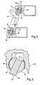
- Figure 2 is a schematic view of a compressor mechanism utilizing the coating of the subject invention;
- Figure 3 is an enlarged fragmentary and cross sectional view of the coating of the subject invention disposed on the ball pocket of a piston of the compressor;
- Figure 4 is an image of the machined surface of the ball pocket;
- Figure 5 is an image like Figure 4 but at a greater magnification;
- Figure 6 is an image of the surface of the ball pocket after an acid solution treatment;
- Figure 7 is like Figure 6 but at a greater magnification;
- Figure 8 is an image of a ball pocket coated with tin after a dry start;
- Figure 9 is an image of a ball pocket coated with the subject invention after a dry start;
- Figure 10 is an image of a ball pocket coated with the subject invention after a dry start;
- Figure 11 is a back scatter electron image of the coating of Figure 10; and
- Figure 12 is an image of a break-in area of a ball pocket coated with the subject invention
- A compressor assembly with which the subject invention is utilized is generally shown in Figures 1, 2 and 3 typically include a
housing 20 supporting a cylinder block 22 presenting a plurality ofcylinder bores 24. Acap 26 closes an open end of thehousing 20 and a plurality of bolts clamp the cylinder block 22 between thehousing 20 and thecap 26. Apiston 28 is disposed for reciprocation in each of thecylinder bores 24. The cylinder block 22 is usually an aluminum alloy. - A
plate 30 presents adrive surface 32 extending transversely to thebores 24. Thisplate 30 is frequently referred to as a swash orwobble plate 30. A mechanism for effecting relative rotation between the cylinder block 22 and theplate 30 for reciprocating thepistons 28 in thecylinder bores 24 includes adrive shaft 34 rotatably supported by thehousing 20 for rotation about an axis. The mechanism described also includes apivot link 36 that allows the angle of theplate 30 to vary, setting the pumping capacity of the compressor. - Each of the
pistons 28 includes a spherical orball pocket 38 and the mechanism including aspherical shoe 40 on eachdrive surface 32 on each side of theplate 30 and in sliding engagement with thepocket 38. The shoes are usually hardened steel and acoating 42 is disposed on the surface of thepocket 38 to engage each of theshoes 40 or on the shoe to engage thepocket 38. - In accordance with the subject invention, the
coating 42 is a composite of solid particles of a lubricant, suspended in an adhesive, bonded to the aluminum alloy defining thepocket 38. More specifically, thecoating 42 comprises particles of polytetrafluoroethylene (PTFE) suspended in an epoxy resin having a low cross-linking characteristic. The particles of PTFE are sub-micron in size and the ratio of PTFE to epoxy resin can range from one half to one and a half to one. The thickness of thecoating 42 is between two and ten microns and preferably substantially four microns. - The
coating 42 material is basically a Polytetrafluoroethylene (PTFE) and epoxy resin composite. In the PTFE/epoxy composite, the PTFE particles function as a solid lubricant and the epoxy resin provides the adhesion to the base substrate and bonds the PTFE particles together. - There are many types of resin that are popular as a bonded polymer base, such as PAI and Phenolic resin. In this invention, an epoxy-based resin was selected for its excellent adhesion to metals and combined properties of strength and toughness. It was determined that by controlling the epoxy cross-linking degree, the resin base is able to obtain excellent toughness and conformability of the
coating 42. This toughness and conformability acted to provide good bearing load support and lubrication of the friction surface. Also, lowering the cross-linking degree improved the conformability of thecoating 42. Therefore, the wear rate of thecoating 42 was reduced. Further more, the epoxy resin formula is water based and has very low VOC emission making it much more environmentally friendly than the historic tin plating/coating 42. Sub-micron sized PTFE powder is used in thecoating 42 as they help thecoating 42 be very precisely applied to, and uniformly distributed on, the ball pocket. The PTFE/resin weight ratio is optimized at about a one to one level but can have a range as previously stated. The high level of solid lubricant provides the high degree of lubricity of thecoating 42. However, it was found that too high of PTFE content would reduce thecoating 42 adhesion strength. The one to one weight ratio is the optimum level. Thecoating 42 also has the advantage of low curing temperature and fast curing time. With curing temperature at 350F for one to two minutes, the curing process is fast and has almost no thermal effect on base metal mechanical properties. - The spray method was used in the development. However, other application methods, such as printing, dispersion or dipping, can also been used with this
coating 42. - An SEM image of a typical surface texture of an as-machined
ball pocket 38 surface is shown in Figure 4 wherein the as-machinedpocket 38 surface is not smooth but has relatively rough turning marks. The magnified view of the as-machined surface in Figure 5 shows the metal flow/smear marks on the surface. Thepiston 28 is made from an Al-Si based alloy, which contains hard silicon particles to provide wear resistance. However, as seen in Figure 5, the smeared aluminum has partially covered the as-machined surface. It is believed that this smeared aluminum is not optimally suited for anti-wear or anti-galling properties. Therefore, the metal surface must be treated to remove the smeared surface aluminum to expose the hard, wear resistance silicon particles in the base alloy. - A chemical polishing/etching method is used to treat the
ball pocket 38 surface. Both acid and alkali based solution have the ability to polish/etch the aluminum alloy. However, the solution base and concentration must be carefully developed to have the desired reaction degree. Also, post-etch surfaces must be free of reaction product or "smut" and other contaminants. The existence of smut or other contaminants will negatively affect thecoating 42 adhesion properties. - An HF and HNO3 acid based solution was used as the surface polishing/etching agent. It was determined that if the
piston 28 was treated with a five percent (5%) solution at room temperature for two to three minutes, the surface would be well prepared for application of thecoating 42. The surface texture after three minutes of treatment is shown in Figures 6 and 7. As compared with Figures 4 and 5, it is obvious that the surface turning marks are much smoother than the as-machined surface condition and the silicon particles are exposed at the surface. Also, some micro pores are generated after the etching process. These micro pores are helpful in providing mechanical interlocking sites for improving the polymer coating's 42 adhesion strength. - Accordingly, the invention provides a method of fabricating a compressor assembly of the type comprising an aluminum alloy cylinder block 22 presenting a plurality of cylinder bores 24 with a
piston 28 reciprocated in each of the cylinder bores 24 as a steelspherical shoe 40 is in sliding engagement with aspherical pocket 38 in eachpiston 28 through acoating 42 on thepocket 38. The method includes the step of applying thecoating 42 of a composite of solid particles of a lubricant suspended in an adhesive bonded to thepocket 38. The method is further defined as applying thecoating 42 comprising solid particles of polytetrafluoroethylene (PTFE) suspended in an epoxy resin. Also included is the step of treating thepocket 38 with an acid based solution prior to applying thecoating 42 and more particularly, treating thepocket 38 with HF and HNO3 acid based solution prior to applying thecoating 42. Preferably, the etching solution is applied from one to three minutes prior to applying thecoating 42. - As alluded to above, the method is further defined as applying an epoxy resin having a low cross linking characteristic, applying particles of PTFE that are sub-micron in size, applying a
coating 42 wherein the ratio of PTFE to epoxy resin is optimally one to one, as applying thecoating 42 in a thickness between two and ten microns, preferably substantially four microns. - Since the
coating 42 is water borne resin based, the VOC contents of thecoating 42 formulation are very low. Therefore, the VOC related environmental issue could be minimized. The requiredcoating 42 technology is simple and therefore suitable to integrate thecoating 42 process into compressor production line. - For the chemical polishing/etching process of the pre-coating 42 surface treatment, the chemicals used are simply inorganic acids that have no heavy metal hazards involved. The wastewater can be neutralized through simple treatments. Therefore, the
entire coating 42 process is environmental friendly and easily in compliance with global environmental regulations. - The following example is a typical test that shows the no-oil-dry-start test comparison of PTFE/epoxy coated
ball pocket 38 verses the tin coated one. The as machinedpistons 28 were dipped into five percent (5%) etching solution for two minutes and rinsed with DI water. The treatedpistons 28 were then preheated to 150-200° F and the PTFE/epoxy coating 42 was sprayed onto the ball pockets 38. Thecoating 42 uses submicron sized PTFE particles and has an optimized 1:1 weight ratio of PTFE/epoxy. The epoxy resin is water based with low cross-linking characteristics. The as-sprayedcoating 42 thickness is about four microns. Theball pocket 38 coatedpistons 28 were then cured at 350° F for two minutes. - Six
pistons 28 with ball pockets 38 that had been coated by PTFE/Epoxy coating 42 were installed in a seven-cylinder A/C compressor. For comparison, one of thepistons 28, with a tin coated/platedball pocket 38 was also installed in the same compressor. By introducing two types ofcoated piston 28 in a same compressor, test condition variation is minimized, and the test results are directly comparable. The compressor was subjected to a no-oil-dry start test. As indicated by the test name, there is no oil in the A/C system during the test. The compressor was engaged at 1800 rpm. After fifty-four seconds, the tin coatedball pocket 38 galled, whereas all of the PTFE/Epoxy coated pockets 38 remain in good condition. Figures 8 and 9 show thepost-test ball pocket 38 surface of tin and PTFE/epoxy coatedpistons 28 respectively. It can be seen that the tin coated surface has been smeared and the aluminum alloy substrate galled. However, the PTFE/epoxy coating 42 remains in excellent condition. From Figure 9, it can be seen that the PTFE/epoxy coating 42 is at the beginning of its wear-in stage. Most of thecoating 42 is in its original condition and few high-spot areas had very smooth wear-in. - A
ball pocket 38 worn surface analysis may be accomplished by looking closely at the PTFE/epoxy coated worn area in Figure 10, which is an SEM secondary electron image that shows thedetailed coating 42 wear-in surface. Figure 10 clearly shows that during the dry-start test, the PTFE/epoxy coatings 42 are very flexibly conformed on the rubbing/friction surface. Thecoating 42 was compressed and deformed but still adequately covered the metal substrate. Figure 11 is a back scatting electron image that shows some more aggressive wear-in area. The light color areas are metal substrate and the dark color areas are remaining PFTE/epoxy coating 42. From Figure 11, it can been seen that after the relatively aggressive wear-in from the dry start test, thecoating 42 is partially damaged and deformed by the rotational movement ofshoe 40 surface. Some of thecoating 42 is worn away as expected. However, the discontinuous dark spots show that there is still a verythin coating 42 film adhered to the metal substrate. The existence of this thin PTFE rich film will continue to provide the self-lubrication characteristic desired from thecoating 42. The uniform turning marks show that the substrate had been protected by the smearedcoating 42 film. - Since the
ball pocket 38 is not well matched to theshoe 40, there are some areas that have higher loading than others. Figure 12 indicates that the original tuning marks at the high load areas have been "polished" during the no oil dry start test. Clearly, the galling tendency is largely reduced by the PTFE/epoxy coating 42 in theball pocket 38 - Obviously, many modifications and variations of the present invention are possible in light of the above teachings. The invention may be practiced otherwise than as specifically described within the scope of the appended claims. For example, submicron sized solid lubricants such as MoS2, WS2 and etc. can also been introduced into this coating.
Claims (22)
- A compressor assembly comprising;a housing (20),a cylinder block (22) presenting a plurality of cylinder bores (24) and supported by said housing (20),a piston (28) disposed for reciprocation in each of said cylinder bores (24),a plate (30) presenting a drive surface (32) extending transversely to said bores (24),a mechanism for effecting relative rotation between said cylinder block (22) and said plate (30) for reciprocating said pistons (28) in said cylinder bores (24),each of said pistons (28) including a spherical pocket (38), said mechanism including a spherical shoe (40) in sliding engagement with said pocket (38),a coating (42) between said pocket (38) and said shoe (40), andcharacterized by said coating (42) being a composite of solid particles of a lubricant suspended in an adhesive bonded to one of said pocket (38) and said shoe (40).
- An assembly as set forth in claim 1 wherein said coating (42) comprises particles of polytetrafluoroethylene (PTFE) suspended in an epoxy resin.
- An assembly as set forth in claim 2 wherein said cylinder is an aluminum alloy.
- An assembly as set forth in claim 3 wherein said shoe (40) is steel and said coating (42) is bounded to said pocket (38).
- An assembly as set forth in claim 3 wherein said epoxy resin has a low cross-linking characteristic.
- An assembly as set forth in claim 3 wherein said particles of PTFE are sub-micron in size.
- An assembly as set forth in claim 3 wherein the ratio of PTFE to epoxy resin is in the range from one half, to one and half, to one.
- An assembly as set forth in claim 3 wherein the thickness of said coating (42) is between two and ten microns.
- An assembly as set forth in claim 3 wherein the thickness of said coating (42) is substantially four microns.
- An assembly as set forth in claim 1 wherein said piston is an aluminum alloy and said shoe (40) is steel, and said coating (42) includes particles of polytetrafluoroethylene (PTFE) suspended in an epoxy resin bonded to said aluminum alloy with the weight ratio of PTFE to epoxy resin being in the range from one half, to one and half, to one.
- An assembly as set forth in claim 10 wherein the thickness of said coating (42) is being between two and ten microns.
- A method of fabricating a compressor assembly of the type comprising a cylinder block (22) presenting a plurality of cylinder bores (24) with a piston (28) reciprocated in each of the cylinder bores (24) as a spherical shoe (40) is in sliding engagement with a spherical pocket (38) in each piston (28) through a coating (42) on the surface of one of the pocket (38) and the shoe (40), said method characterized by the steps of;
applying the coating (42) of a composite of solid particles of a lubricant suspended in an adhesive bonded to one of the pocket (38) and the shoe (40). - A method as set forth in claim 12 further defined as applying the coating (42) comprising solid particles of polytetrafluoroethylene (PTFE) suspended in an epoxy resin.
- A method as set forth in claim 13 including the step of treating the surface with an acid based solution prior to applying the coating (42).
- A method as set forth in claim 13 including the step of treating the surface with an HF and HNO3 acid based solution prior to applying the coating (42).
- A method as set forth in claim 13 including the step of treating the surface with five percent of an HF and HNO3 acid based solution for one to three minutes prior to applying the coating (42).
- A method as set forth in claim 13 further defined as applying the coating (42) to a sphere of an aluminum alloy defining the pocket (38) for sliding engagement with a shoe (40) of steel.
- A method as set forth in claim 17 further defined as applying an epoxy resin having a low cross linking characteristic.
- A method as set forth in claim 17 further defined as applying particles of PTFE that are sub-micron in size.
- A method as set forth in claim 17 further defined as applying a coating (42) wherein the ratio of PTFE to epoxy resin is optimally one to one.
- A method as set forth in claim 17 further defined as applying the coating (42) in a thickness between two and ten microns.
- A method as set forth in claim 17 further defined as applying the coating (42) in a thickness of substantially four microns.
Applications Claiming Priority (1)
| Application Number | Priority Date | Filing Date | Title |
|---|---|---|---|
| US11/327,988 US7281465B2 (en) | 2006-01-09 | 2006-01-09 | Compressor piston ball pocket coating |
Publications (2)
| Publication Number | Publication Date |
|---|---|
| EP1816349A2 true EP1816349A2 (en) | 2007-08-08 |
| EP1816349A3 EP1816349A3 (en) | 2012-06-06 |
Family
ID=38171096
Family Applications (1)
| Application Number | Title | Priority Date | Filing Date |
|---|---|---|---|
| EP06077270A Withdrawn EP1816349A3 (en) | 2006-01-09 | 2006-12-18 | Compressor piston ball pocket coating |
Country Status (2)
| Country | Link |
|---|---|
| US (1) | US7281465B2 (en) |
| EP (1) | EP1816349A3 (en) |
Families Citing this family (7)
| Publication number | Priority date | Publication date | Assignee | Title |
|---|---|---|---|---|
| US7549326B2 (en) * | 2007-02-06 | 2009-06-23 | Gm Global Technology Operations, Inc. | Piston delamination testing apparatus |
| US20090246049A1 (en) * | 2008-03-27 | 2009-10-01 | Oil Flow Usa, Inc. | Coated cylinder for walking beam compressor |
| US7730939B2 (en) * | 2008-03-27 | 2010-06-08 | Oil Flow Usa, Inc. | Safety clamp for walking beam compressor |
| US8047820B2 (en) * | 2008-03-27 | 2011-11-01 | Oil Flow Usa, Inc. | Stuffing box for walking beam compressor |
| CN102536742B (en) * | 2012-01-13 | 2014-12-24 | 重庆建设摩托车股份有限公司 | Method for machining movable friction parts of air compressors |
| US9752570B2 (en) * | 2014-02-13 | 2017-09-05 | S-RAM Dynamics | Variable displacement compressor and expander |
| WO2023181980A1 (en) * | 2022-03-24 | 2023-09-28 | 株式会社リケン | Sliding mechanism |
Family Cites Families (16)
| Publication number | Priority date | Publication date | Assignee | Title |
|---|---|---|---|---|
| US5630355A (en) * | 1993-06-21 | 1997-05-20 | Kabushiki Kaisha Toyoda Jidoshokki Seisakusho | Reciprocating type compressor with improved cylinder block |
| US5655432A (en) * | 1995-12-07 | 1997-08-12 | Ford Motor Company | Swash plate with polyfluoro elastomer coating |
| US6694864B2 (en) * | 1997-10-09 | 2004-02-24 | Kabushiki Kaisha Toyota Jidoshokki | Swash plate type compressor |
| JPH11193780A (en) * | 1997-12-26 | 1999-07-21 | Toyota Autom Loom Works Ltd | Single-headed piston swash plate type compression machine and method for manufacturing swash plate |
| JP2000170657A (en) * | 1998-12-09 | 2000-06-20 | Toyota Autom Loom Works Ltd | Compressor piston and coating method therefor |
| JP2000257555A (en) * | 1999-03-08 | 2000-09-19 | Toyota Autom Loom Works Ltd | Compressor |
| JP2001263227A (en) * | 2000-03-21 | 2001-09-26 | Toyota Autom Loom Works Ltd | Coating film forming method in swash plate of swash plate type compressor and swash plate therefor |
| JP2002174169A (en) * | 2000-12-06 | 2002-06-21 | Toyota Industries Corp | Aluminium shoe |
| KR100432948B1 (en) * | 2000-07-14 | 2004-05-28 | 가부시키가이샤 도요다 지도숏키 | One side inclination plate type compressor |
| JP2002257045A (en) * | 2001-03-02 | 2002-09-11 | Toyota Industries Corp | Piston type compressor |
| JP3948259B2 (en) * | 2001-05-21 | 2007-07-25 | 株式会社豊田自動織機 | Shoe for a swash plate compressor and manufacturing method thereof |
| JP2003049766A (en) * | 2001-08-03 | 2003-02-21 | Toyota Industries Corp | Sliding part and compressor |
| JP3918516B2 (en) * | 2001-11-07 | 2007-05-23 | 株式会社豊田自動織機 | Swash plate compressor |
| JP2003184743A (en) * | 2001-12-12 | 2003-07-03 | Toyota Industries Corp | Shoe for swash plate type compressor and swash type compressor provided therewith |
| JP4232506B2 (en) * | 2002-06-24 | 2009-03-04 | 株式会社豊田自動織機 | Sliding parts |
| US6761931B1 (en) * | 2003-01-17 | 2004-07-13 | Delphi Technologies, Inc. | Method for piston coating |
-
2006
- 2006-01-09 US US11/327,988 patent/US7281465B2/en not_active Expired - Lifetime
- 2006-12-18 EP EP06077270A patent/EP1816349A3/en not_active Withdrawn
Also Published As
| Publication number | Publication date |
|---|---|
| US20070157799A1 (en) | 2007-07-12 |
| US7281465B2 (en) | 2007-10-16 |
| EP1816349A3 (en) | 2012-06-06 |
Similar Documents
| Publication | Publication Date | Title |
|---|---|---|
| EP1433838B1 (en) | Slide member | |
| JP6417400B2 (en) | Sliding engine parts | |
| US6983681B2 (en) | Sliding member | |
| US5655432A (en) | Swash plate with polyfluoro elastomer coating | |
| EP2264316B1 (en) | Swash plate and method of manufacturing same | |
| CN1215267C (en) | slider | |
| US6815400B2 (en) | Method for forming solid film lubricant | |
| EP2623780B1 (en) | Swash plate of swash plate compressor and swash plate compressor | |
| EP1035326A2 (en) | Compressor coating | |
| EP2402606A1 (en) | Self-lubricating wearable coating swash plate and the production process thereof | |
| EP1281863B1 (en) | Compressor coating | |
| US7331274B2 (en) | Sliding film, sliding member, composition for sliding film, sliding device, swash-plate type compressor, process for forming sliding film, and process for producing sliding member | |
| KR20110100259A (en) | bearing | |
| WO2014123159A1 (en) | Sliding member, method for manufacturing same, and compressor swash plate using sliding member | |
| US7281465B2 (en) | Compressor piston ball pocket coating | |
| US6192784B1 (en) | Swash plate compressor | |
| US20110052112A1 (en) | Sliding member for thrust bearing | |
| JPWO1998036173A1 (en) | Swash plate compressor | |
| KR101472373B1 (en) | Composition of surface coating for compressor sliding part and compressor sliding part using thereof | |
| KR102373093B1 (en) | Resin composition and sliding member | |
| US11421173B2 (en) | Resin composition and sliding member | |
| CN1241245A (en) | Swash plate compressor | |
| US20020046646A1 (en) | Compressors | |
| WO2001007786A1 (en) | Method for forming film on machine part | |
| KR20020092483A (en) | Swash plate and compressor utilizing the same |
Legal Events
| Date | Code | Title | Description |
|---|---|---|---|
| PUAI | Public reference made under article 153(3) epc to a published international application that has entered the european phase |
Free format text: ORIGINAL CODE: 0009012 |
|
| AK | Designated contracting states |
Kind code of ref document: A2 Designated state(s): AT BE BG CH CY CZ DE DK EE ES FI FR GB GR HU IE IS IT LI LT LU LV MC NL PL PT RO SE SI SK TR |
|
| AX | Request for extension of the european patent |
Extension state: AL BA HR MK YU |
|
| RIN1 | Information on inventor provided before grant (corrected) |
Inventor name: GABEL, TIMOTHY M. Inventor name: ZHU, MINGGUANG Inventor name: COCHRAN, THEODORE R. |
|
| PUAL | Search report despatched |
Free format text: ORIGINAL CODE: 0009013 |
|
| AK | Designated contracting states |
Kind code of ref document: A3 Designated state(s): AT BE BG CH CY CZ DE DK EE ES FI FR GB GR HU IE IS IT LI LT LU LV MC NL PL PT RO SE SI SK TR |
|
| AX | Request for extension of the european patent |
Extension state: AL BA HR MK RS |
|
| RIC1 | Information provided on ipc code assigned before grant |
Ipc: F04B 27/08 20060101AFI20120503BHEP |
|
| STAA | Information on the status of an ep patent application or granted ep patent |
Free format text: STATUS: THE APPLICATION IS DEEMED TO BE WITHDRAWN |
|
| 18D | Application deemed to be withdrawn |
Effective date: 20120703 |