EP1816040A1 - Automobile key system - Google Patents
Automobile key system Download PDFInfo
- Publication number
- EP1816040A1 EP1816040A1 EP06002008A EP06002008A EP1816040A1 EP 1816040 A1 EP1816040 A1 EP 1816040A1 EP 06002008 A EP06002008 A EP 06002008A EP 06002008 A EP06002008 A EP 06002008A EP 1816040 A1 EP1816040 A1 EP 1816040A1
- Authority
- EP
- European Patent Office
- Prior art keywords
- automobile
- key
- user
- electronic unit
- state
- Prior art date
- Legal status (The legal status is an assumption and is not a legal conclusion. Google has not performed a legal analysis and makes no representation as to the accuracy of the status listed.)
- Granted
Links
- 230000004044 response Effects 0.000 claims abstract description 7
- 230000000994 depressogenic effect Effects 0.000 claims description 20
- 238000000034 method Methods 0.000 claims description 9
- 230000004913 activation Effects 0.000 claims description 5
- 238000004519 manufacturing process Methods 0.000 abstract description 2
- 230000000881 depressing effect Effects 0.000 description 8
- 239000003550 marker Substances 0.000 description 5
- 230000000007 visual effect Effects 0.000 description 4
- 230000008901 benefit Effects 0.000 description 3
- 230000008859 change Effects 0.000 description 3
- 239000007858 starting material Substances 0.000 description 3
- 238000004378 air conditioning Methods 0.000 description 2
- 230000000295 complement effect Effects 0.000 description 2
- 239000000446 fuel Substances 0.000 description 2
- 230000014509 gene expression Effects 0.000 description 2
- 230000007246 mechanism Effects 0.000 description 2
- 238000004891 communication Methods 0.000 description 1
- 230000007812 deficiency Effects 0.000 description 1
- 238000001514 detection method Methods 0.000 description 1
- 238000010586 diagram Methods 0.000 description 1
- 238000000605 extraction Methods 0.000 description 1
- 230000014759 maintenance of location Effects 0.000 description 1
- 230000004048 modification Effects 0.000 description 1
- 238000012986 modification Methods 0.000 description 1
- 230000002093 peripheral effect Effects 0.000 description 1
- 238000003825 pressing Methods 0.000 description 1
- 230000002250 progressing effect Effects 0.000 description 1
- 230000000750 progressive effect Effects 0.000 description 1
- 230000005855 radiation Effects 0.000 description 1
- 238000009877 rendering Methods 0.000 description 1
- 230000008439 repair process Effects 0.000 description 1
- 230000007704 transition Effects 0.000 description 1
Images
Classifications
-
- B—PERFORMING OPERATIONS; TRANSPORTING
- B60—VEHICLES IN GENERAL
- B60R—VEHICLES, VEHICLE FITTINGS, OR VEHICLE PARTS, NOT OTHERWISE PROVIDED FOR
- B60R25/00—Fittings or systems for preventing or indicating unauthorised use or theft of vehicles
- B60R25/20—Means to switch the anti-theft system on or off
- B60R25/2063—Ignition switch geometry
-
- B—PERFORMING OPERATIONS; TRANSPORTING
- B60—VEHICLES IN GENERAL
- B60R—VEHICLES, VEHICLE FITTINGS, OR VEHICLE PARTS, NOT OTHERWISE PROVIDED FOR
- B60R25/00—Fittings or systems for preventing or indicating unauthorised use or theft of vehicles
- B60R25/01—Fittings or systems for preventing or indicating unauthorised use or theft of vehicles operating on vehicle systems or fittings, e.g. on doors, seats or windscreens
- B60R25/04—Fittings or systems for preventing or indicating unauthorised use or theft of vehicles operating on vehicle systems or fittings, e.g. on doors, seats or windscreens operating on the propulsion system, e.g. engine or drive motor
Definitions
- the present invention relates to automobile key systems, for example to electronic automobile key systems operable to be user activated using electronic keys and operable to support selection of preferred automobile functions by actuation of automobile switches. Moreover, the present invention also relates to methods of selecting preferred automobile functions via such automobile key systems.
- Automobile key systems are known for user selection of preferred automobile functions.
- the expression "automobile” is to be construed to relate to road vehicles; such vehicles include personal road vehicles, freight vehicles, busses, motorcycles and similar.
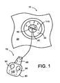
- FIG. 1 An example of a convention automobile key system is depicted, from a user's viewpoint, in Figure 1.
- a user accessible part of the automobile key system is indicated generally by 10.
- the system 10 includes a dash-board panel 20, for example a panel in front of or adjacent to a user when seated in a driver's seat within an automobile equipped with the system 10.
- a key mechanism comprising a stationary peripheral component 30 including angular surface markers "0", "1", "2” and “3"; the markers "0", “1", “2” and “3” also relate to corresponding operating states "0", "1", “2” and “3” respectively of the automobile which will be elucidated later.
- the key mechanism further comprises an inner barrel component 40 including a slot 50 for receiving in operation a spatially coded blade 60 of a key indicated generally by 70.
- the key 70 includes a body portion 80 including one or more user push switches 90 and optionally an electronic circuit 100 therein.
- the electronic circuit 100 includes one or more transducers therein, for example infer-red (IR) emitting diodes and IR detector diodes, for enabling the key 70 to be used remotely to the automobile for remotely accessing the automobile and/or for remotely locking or disabling the automobile.
- IR infer-red
- the key 70 is remote from the slot 50 such that a transverse elongate axis 110 of the slot 50 is aligned with the surface marker "0" as illustrated in Figure 1.
- the slot 50 aligned to the surface marker "0" is representative of the automobile being immobilized and locked with its engine non-active, namely in the state "0",
- the user When the user is desirous to unlock the automobile, to energize its engine to drive away, or to invoke one or more functions of the automobile, the user firstly gains access to an interior region of the automobile; such access can either be remotely using the one or more push switches 90 in conjunction with the electronic circuit 100 emitting radiation remotely receivable at the automobile for unlocking the automobile, or by the user physically inserting the blade 60 of the key 70 into a door lock of the automobile for gaining access.
- the user for example when seated in the driver's seat of the automobile, inserts the blade 60 into the slot 50 and can invoke various functions of the automobile by turning the key 70 so as to align the axis 110 with other of the surface markers, namely "1". "2" or "3''.
- the system 10 is operable to apply a resilient rotational force relating to the slot 50 being rotated so that its axis 110 is aligned to the surface marker "3" corresponding to the state "3” to bias the axis 110 of the slot 50 towards the surface marker "2" corresponding to the state "2".
- a resilient rotational force relating to the slot 50 being rotated so that its axis 110 is aligned to the surface marker "3" corresponding to the state "3” to bias the axis 110 of the slot 50 towards the surface marker "2" corresponding to the state "2".
- Such resilient bias is tactile and prevents the user invoking a starter motor of the automobile for longer than necessary when starting the automobile; moreover, the resilient bias also renders it clear to users when the state "3" is invoked.
- the known system 10 has several benefits. Firstly, the user is only able to select one of the surface markings "0", “1”. “2" and “3" at any given instance of time, namely only one corresponding state of the automobile at any instant. Secondly, a presence of the surface markers provides the user with a visual indication of which functions of the automobile have been invoked.
- the key 70 operating In combination with the inner barrel component 40 is susceptible to providing the user with a tactile indication of a function of the automobile invoked by the user,
- the inner barrel component 40 being specifically adapted to complement the spatial features included on the blade 60, namely arrangement of notches and slots machined therein, the system 10 is able to resist third parties with incompatible keys gaining access to functions of the automobile should such third parties be able to gain, for example by forced entry, access into an inner region of the automobile.
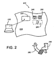
- the electronic key system 10 can be achieved as depicted in Figure 2; the electronic key system is indicated generally by 200.
- the system 200 includes a user-retainable key 230 which is operable to be received within a socket 220 in a dashboard panel 210 of an automobile for accessing functions of the automobile: the key 230 beneficially includes the aforesaid electronic circuit 100 or a suitable variant thereof.
- the key 230 beneficially includes the aforesaid electronic circuit 100 or a suitable variant thereof.
- switches 240, 250 for example press buttons, on the dashboard panel 210.
- Such an implementation of the electronic key system 200 is presently substantially utilized by certain prestige automobile manufacturers.
- the switches can correspond to decrement and increment switches for selecting down and up the sequence of functions associated with the states “0", “1", “2” and “3".
- the automobile can optionally be provided with a sensor associated with a brake foot pedal or accelerator foot pedal 280 of the automobile for sensing when the pedal 280 is depressed by a foot 290 of the user.
- the user inserting the electronic key 230 into the socket 220 of the dashboard panel 210, pressing the pedal 280 and then using the switches 240, 250 to select state “3” can be used to commence cranking and ignition in an engine of the automobile.
- the user is operable to depress the switches 240, 250 to progress sequentially effectively through states “0" to "1” to "2” to “3” and then back to state "2" for driving away.
- the states “0", “1", “2” and “3” can have associated automobile functions as depicted in Table 1.
- Table 1 State, surface marker Associated automobile function "0" "Key in” state; in the system 10, allows extraction of the key 70 from the slot 50 or introduction of the key 70 into the slot 50 "1" "Access” state for invoking "waiting" functions of the automobile, for example infotainment, automobile interior air conditioning "2" “Ignition” state for maintaining an engine running as well as power intensive functions such as energizing headlights and tail-lights of the automobile "3" “Cranking” state for invoking cranking of the engine of the automobile, fuel supply to the engine, as well as “ignition” state functions and "access” functions; in the system 200, firstly depressing the pedal 280 and then invoking the state "3" is operable to crank and start the engine
- An object of the present invention is to provide an improved automobile key system.
- an automobile key system operable to enable user access to functions of an automobile by using an electronic key, said system comprising:
- the invention is of advantage in that use of the length of time the switch is depressed for differential selection of states is capable of simplifying implementation of the key system and rendering it easier for users to employ, thereby potentially increasing safety and convenience.
- the switch arrangement comprises only a single switch for user-invoking the electronic unit into the mutually different states.
- Use of a single switch is not only capable of simplifying dash-board panel design for ergonomic and safety reasons, but also improving ease of use of the key system to the user and also potentially reducing manufacturing cost of the automobile.
- the electronic unit is operable to be user-invoked into one or more of the following states:
- the socket arrangement is provided with one or more actuators for retaining the key in position in the socket arrangement when any one of the third, fourth and fifth states are invoked in the electronic unit and the automobile is still In a state of motion.
- the electronic unit is operable to return to the first or second state from any one of the third, fourth and fifth states only when the automobile is in a stationary state.
- the automatic key system is implemented such that the electronic unit is operable to render the automobile non-immobilized in an event of the key being removed from the socket arrangement whilst the automobile is in motion.
- the length of the time period during which the switch of the switch arrangement requires to be user-depressed to select the fourth state is greater than 500 milliseconds, more preferably greater than 1 second, and most preferably greater than 2 seconds.
- durations of time period are possible but are beneficially chosen so that the user does not find the key system to be inconveniently slow in responding, for example not more than 15 seconds as a preferred maximum.
- the third state is invoked when the switch is depressed for a time period less than a threshold time period
- the fourth state is invoked when the switch is depressed for a time period greater than the threshold time period.
- Use of the threshold period is of benefit to unambiguously distinguish between selection of the third state and the fourth state.
- the electronic unit is coupled to one or more user-depressible pedals of the automobile for sensing a state of depression of the one or more pedals, the electronic unit being operable in an event of one or more of the pedals being depressed followed by the switch being depressed to be invoked into the fifth state to cause cranking of the engine of the automobile.
- the one or more user-depressible pedals include one or more of: a clutch pedal, a brake pedal, an accelerator pedal.
- the electronic unit is operable to automatically progress from the fifth state to the fourth state in response to the engine of the automobile being successfully started during ignition.
- Such automatic switching from the fifth state to the fourth state is capable of preventing over-use of a starter motor of the automobile, thereby potentially improving automobile operating longevity and reliability.
- the second and third states are combined as one state susceptible to being invoked in the electronic unit.
- a method of selectively user-invoking an automobile key system into mutually different states the system being operable to enable user access to functions of an automobile by using an electronic key, the system comprising:
- the switch arrangement comprises only a single switch for user-invoking the electronic unit into the mutually different states.
- a third state is invoked when the switch is depressed for a time period less than a threshold time period
- a fourth state is invoked when the switch is depressed for a time period greater than the threshold time period, the third state corresponding to activation of user-access functions of the automobile, and the fourth state corresponding to activation of ignition functions of the automobile
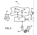
- the key system is indicated generally by 300.
- the system 300 includes a region of the aforesaid automobile dashboard panel 210 provided with the aforementioned socket 220 operable to receive the electronic key 230.
- the system 200 is distinguished in that it includes a single switch, namely the switch 240, without any form of associated display.
- the system 300 further includes an electronic logic unit 310, for example implemented using computing hardware and/or dedicated application-specific logic circuits.
- the unit 310 is coupled in communication with the switch 240, with the socket 220 for communicating with the electronic circuit 100 of the electronic key 230, and with a control data-bus 320 of the automobile.
- the data-bus 320 caters for battery management, engine management and security management of the automobile.
- the data-bus 230 is, for example, coupled to a starter motor 330 of the automobile for cranking its engine when the automobile is to be started.
- the logic unit 310 of the key system 300 is also coupled to a sensor for sensing a position of the pedal 280 actuated by the foot 290 of the user for detecting whether or not the pedal 280 is depressed in operation.
- the electronic unit 310 When the user inserts the electronic key 230 into the socket 220 of the dashboard panel 210, the electronic unit 310 is operable to interrogate the electronic key 230 to determine whether or not the key 230 is operable to provide identification data to the electronic unit 310 which the electronic unit 310 recognizes as being indicative of bona fide access to the automobile.
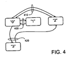
- the electronic unit 310 In an event that the electronic unit 310 identifies the key 230 to be unauthorized, for example in a situation of a break-in into the automobile, the electronic unit 310 communicates with the data-bus 320 of the automobile to ensure that the automobile is immobilized; optionally, in such a situation, the electronic unit 310 is operable to communicate to the data-bus 320 to raise an audio and/or visual alarm. Conversely, in an event that the electronic unit 310 identifies the key 230 to be authorized and corresponding to the automobile, the electronic unit 310 is operable to switch to a state "0" as depicted in Figure 4. As elucidated in Table 1 in the foregoing, the state "0" corresponds to a "key in” situation, namely akin to the key 70 being inserted into the slot 50 in the system 10 depicted in Figure 1.
- the user When the state "0" is established as depicted in Figure 4, the user briefly depresses the switch 240 for a relatively short period to invoke the electronic unit 310 to switch to the state "1", namely to the "access” state as elucidated in the aforesaid Table 1.
- the electronic unit 310 When the electronic unit 310 has attained the state "1”, the user is able to depress the switch again 240 for a substantially similar relatively short period for causing the electronic unit 310 to be operable to switch from being in the state "1" back to the state "0".
- the short period is preferably not more than 2 seconds, more preferably not more than 1 second, and most preferably not more than 500 milliseconds.
- a change of states of the electronic unit 310 associated with the relatively short period of depression of the switch 240 is denoted by 400 in Figure 4.
- the state "1" has been selected by the user by depressing the switch 240 for the short period
- the user can then subsequently invoke the state "2" from the state "1" in the electronic unit 310 by depressing the switch 240 for a relatively long period; the relatively long period will be further elucidated below.
- the user depresses the switch 240 for a relatively long period to invoke the electronic unit 310 to switch to the state "2", namely to the "ignition” state as elucidated in the aforesaid Table 1. If the user depresses the switch again 240 for a substantially similar long period, the electronic unit 310 is operable to switch from being in the state "2" back to the state "0".
- the user can depress the switch 240 for the relatively short period or the relatively long period to cause the electronic unit 310 to return back to assume the state "0".
- a change of states of the electronic unit 310 associated with the relatively long period of depression of the switch 240 is identified by 410 in Figure 4.
- the relatively long period is preferably complementary to the aforesaid relatively period.
- the relatively long period is preferably more than 500 milliseconds, more preferably more than 1 second and most preferably more than 2 seconds.
- the user employs his/her foot 290 to depress the pedal 280 and, whilst the pedal 280 is depressed, then depresses the switch 240 to cause the electronic unit 310 to assume the state "3" as provided in Table 1 to initiate cranking of the engine of the automobile.
- the electronic unit 310 is operable, preferably automatically without intervention of the user, to switch to the state "2" to sustain running of the engine.
- Subsequent removal of the key from the socket 220 or subsequent depression of the switch 240 is operable to cause the electronic unit 310 to assume state "0"; however, in order to reduce a risk of the automobile being immobilized in dangerous circumstances, for example a child seated in a front seat of the automobile adjacent to the user inadvertently removes the key 230 or depresses the switch 240 in a situation of motorway, turnpike or highway driving, the electronic unit 310 is preferable operable to check that the automobile is stationary before progressing to state "0".
- the state "3" can be invoked by the user from one or more of the states “1" or “2” by depressing the pedal 280 and, whilst the pedal 280 is depressed, depressing the switch 240.
- the electronic unit 310 is configurable so that the user can depress the switch 240 to invoke from the state "2" any one of states “0" or "1” in a situation when the automobile is moving; in such a situation, removal of the key 230 is prevented and the automobile is not immobilized.
- the socket 220 is provided with a solenoid actuator operable to lock the key 230 into position into the socket 220 to resist user removal therefrom when the electronic unit 310 is operable to be in any of the states "1", “2" and "3"; such a manner of operation with regard to key retention is more akin to a behavior of the system 10 illustrated in Figure 1 as elucidated in the foregoing. Transition of the electronic unit 310 to and from the cranking state "3" is denoted by 420 in Figure 4.
- the electronic unit 310 can be user-set to the state "2" as elucidated in the foregoing so that lights of the automobile, for example front headlamps and rear tail lights, are lit during towing for safety purposes.
- the system 300 is capable of supporting such operation during towing by way of the switch 240 being user-depressed as described in the foregoing for the aforesaid relatively long period to select the state "2".
- the system 300 is susceptible to being simplified by effectively combining states "0" and "1” so that an act of inserting the key 230 into the socket 220 can be operable to invoke the state "1" in the electronic unit 310 whereas removal of the key 230 invokes state "0" which is preferably of sufficiently low power consumption so as not to drain a battery of the automobile over an idle period of several months.
- depressing the switch 240 without the pedal 280 being depressed invokes the state "2”
- depressing of the pedal 280 followed by depressing the switch 240 is operable to invoke the state "3”
- the electronic unit 310 is preferable automatically operable to change from the state "3" to the state "2" on successful activation of the engine of the automobile.
- system 300 is susceptible to being simplified to dispense with the state "1" and to allocate its associated functions either to the state “0" or to the state "2": for example, infotainment and air-conditioning functions can be rendered available to the user within the automobile irrespective of whether or not the key 230 is installed in the socket 220.
- the single switch 240 is supplemented with a simple form of display, for example an alpha-numerical display or simply one or more incandescent lamps, light emitting diodes (LEDs) or similar installed within or around the switch 240; the display is operable to provide at least a very simple form of indication indicative of which state the electronic unit 310 has attained in operation.
- a simple form of display for example an alpha-numerical display or simply one or more incandescent lamps, light emitting diodes (LEDs) or similar installed within or around the switch 240; the display is operable to provide at least a very simple form of indication indicative of which state the electronic unit 310 has attained in operation.
Landscapes
- Engineering & Computer Science (AREA)
- Mechanical Engineering (AREA)
- Lock And Its Accessories (AREA)
Abstract
Description
- The present invention relates to automobile key systems, for example to electronic automobile key systems operable to be user activated using electronic keys and operable to support selection of preferred automobile functions by actuation of automobile switches. Moreover, the present invention also relates to methods of selecting preferred automobile functions via such automobile key systems.
- Automobile key systems are known for user selection of preferred automobile functions. The expression "automobile" is to be construed to relate to road vehicles; such vehicles include personal road vehicles, freight vehicles, busses, motorcycles and similar.
- An example of a convention automobile key system is depicted, from a user's viewpoint, in Figure 1. A user accessible part of the automobile key system is indicated generally by 10. The
system 10 includes a dash-board panel 20, for example a panel in front of or adjacent to a user when seated in a driver's seat within an automobile equipped with thesystem 10. In a region of the dash-board panel 20, there is mounted a key mechanism comprising a stationaryperipheral component 30 including angular surface markers "0", "1", "2" and "3"; the markers "0", "1", "2" and "3" also relate to corresponding operating states "0", "1", "2" and "3" respectively of the automobile which will be elucidated later. The key mechanism further comprises aninner barrel component 40 including aslot 50 for receiving in operation a spatially codedblade 60 of a key indicated generally by 70. Thekey 70 includes abody portion 80 including one or moreuser push switches 90 and optionally anelectronic circuit 100 therein. Optionally, theelectronic circuit 100 includes one or more transducers therein, for example infer-red (IR) emitting diodes and IR detector diodes, for enabling thekey 70 to be used remotely to the automobile for remotely accessing the automobile and/or for remotely locking or disabling the automobile. - When the automobile is in a locked or disabled state, the
key 70 is remote from theslot 50 such that a transverseelongate axis 110 of theslot 50 is aligned with the surface marker "0" as illustrated in Figure 1. Theslot 50 aligned to the surface marker "0" is representative of the automobile being immobilized and locked with its engine non-active, namely in the state "0", - When the user is desirous to unlock the automobile, to energize its engine to drive away, or to invoke one or more functions of the automobile, the user firstly gains access to an interior region of the automobile; such access can either be remotely using the one or
more push switches 90 in conjunction with theelectronic circuit 100 emitting radiation remotely receivable at the automobile for unlocking the automobile, or by the user physically inserting theblade 60 of thekey 70 into a door lock of the automobile for gaining access. Next, the user, for example when seated in the driver's seat of the automobile, inserts theblade 60 into theslot 50 and can invoke various functions of the automobile by turning thekey 70 so as to align theaxis 110 with other of the surface markers, namely "1". "2" or "3''. Optionally, thesystem 10 is operable to apply a resilient rotational force relating to theslot 50 being rotated so that itsaxis 110 is aligned to the surface marker "3" corresponding to the state "3" to bias theaxis 110 of theslot 50 towards the surface marker "2" corresponding to the state "2". Such resilient bias is tactile and prevents the user invoking a starter motor of the automobile for longer than necessary when starting the automobile; moreover, the resilient bias also renders it clear to users when the state "3" is invoked. - The
known system 10 has several benefits. Firstly, the user is only able to select one of the surface markings "0", "1". "2" and "3" at any given instance of time, namely only one corresponding state of the automobile at any instant. Secondly, a presence of the surface markers provides the user with a visual indication of which functions of the automobile have been invoked. Thirdly, the key 70 operating In combination with theinner barrel component 40 is susceptible to providing the user with a tactile indication of a function of the automobile invoked by the user, On account of theinner barrel component 40 being specifically adapted to complement the spatial features included on theblade 60, namely arrangement of notches and slots machined therein, thesystem 10 is able to resist third parties with incompatible keys gaining access to functions of the automobile should such third parties be able to gain, for example by forced entry, access into an inner region of the automobile. - There is a progressive trend in automobile design to implement various automobile systems in electronic form, for example electronic engine management systems, electronic battery management systems in hybrid automobiles utilizing electric motor traction, and electronic brake control systems to mention a few examples. Contemporarily, there have been attempts to replace the
key system 10 with an electronic equivalent implementation. Such an evolution is not without associated technical issues as will now be described. - An electronic implementation of the
key system 10 can be achieved as depicted in Figure 2; the electronic key system is indicated generally by 200. Thesystem 200 includes a user-retainable key 230 which is operable to be received within asocket 220 in adashboard panel 210 of an automobile for accessing functions of the automobile: the key 230 beneficially includes the aforesaidelectronic circuit 100 or a suitable variant thereof. Instead of mechanically rotating thekey 230 in such anelectronic system 200, there are included one ormore switches dashboard panel 210. Such an implementation of theelectronic key system 200 is presently substantially utilized by certain prestige automobile manufacturers. In practice, users find thesystem 200 unsatisfactory because, unlike thesystem 10, the users are not able to immediately appreciate which of the states "0", "1", "2" and "3" and associated functions of the automobile have been invoked; there is neither tactile feedback nor visual feedback regarding a state that has been invoked. One possible solution to such a deficiency is optionally to include adisplay 260 to provide the user with a visual indication of selected state. However, the solution introduces further issues regarding a cost of thedisplay 260 and an area that it occupies on thedashboard panel 210. Moreover, there is a further ergonomic aspect that contemporary vehicle design favors simple dashboard panel design for safety aspects so that users are not bewildered and distracted by a vast array of automobile controls. In one implementation of thesystem 200, the switches can correspond to decrement and increment switches for selecting down and up the sequence of functions associated with the states "0", "1", "2" and "3". The automobile can optionally be provided with a sensor associated with a brake foot pedal oraccelerator foot pedal 280 of the automobile for sensing when thepedal 280 is depressed by afoot 290 of the user. For example, the user inserting theelectronic key 230 into thesocket 220 of thedashboard panel 210, pressing thepedal 280 and then using theswitches switches - Beneficially, the states "0", "1", "2" and "3" can have associated automobile functions as depicted in Table 1.
Table 1: State, surface marker Associated automobile function "0" "Key in" state; in the system 10, allows extraction of thekey 70 from theslot 50 or introduction of thekey 70 into theslot 50"1" "Access" state for invoking "waiting" functions of the automobile, for example infotainment, automobile interior air conditioning "2" "Ignition" state for maintaining an engine running as well as power intensive functions such as energizing headlights and tail-lights of the automobile "3" "Cranking" state for invoking cranking of the engine of the automobile, fuel supply to the engine, as well as "ignition" state functions and "access" functions; in the system 200, firstly depressing thepedal 280 and then invoking the state "3" is operable to crank and start the engine - Despite the
system 200 being susceptible to being utilized by contemporary users, it does not represent an optimal arrangement regarding simplicity of operation, simple ergonomics, efficient use of dash board area and reduced cost of implementation. - An object of the present invention is to provide an improved automobile key system.
- According to a first aspect of the invention, there is provided an automobile key system operable to enable user access to functions of an automobile by using an electronic key, said system comprising:
- (a) a socket arrangement for receiving the key;
- (b) a switch arrangement for user selection of one or more functions of the automobile; and
- (c) an electronic unit operable to communicate with the key and operable to be user-invoked into one or more operating states when the key is acceptable to said electronic unit,
- The invention is of advantage in that use of the length of time the switch is depressed for differential selection of states is capable of simplifying implementation of the key system and rendering it easier for users to employ, thereby potentially increasing safety and convenience.
- Preferably, in the key system, the switch arrangement comprises only a single switch for user-invoking the electronic unit into the mutually different states. Use of a single switch is not only capable of simplifying dash-board panel design for ergonomic and safety reasons, but also improving ease of use of the key system to the user and also potentially reducing manufacturing cost of the automobile.
- Preferably, in the automobile key system, the electronic unit is operable to be user-invoked into one or more of the following states:
- (a) a first state corresponding to the key being spatially remote from said socket arrangement;
- (b) a second state corresponding to the key being engaged into the socket arrangement for enabling the electronic unit to interrogate the key:
- (c) a third state corresponding to the key being engaged into the socket arrangement and the electronic unit being operable to activate user-access functions of the automobile;
- (d) a fourth state corresponding to the key being engaged into the socket arrangement and the electronic unit being operable to activate ignition functions of the automobile; and
- (e) a fifth state corresponding to the key being engaged into the socket arrangement and the electronic unit being operable to activate engine cranking functions of the automobile for starting an engine of the automobile.
- Preferably, in order to improve safety by avoiding dangerous consequences of the key being Inadvertently removed from the socket arrangement whilst the automobile is functioning, in the automobile key system, the socket arrangement is provided with one or more actuators for retaining the key in position in the socket arrangement when any one of the third, fourth and fifth states are invoked in the electronic unit and the automobile is still In a state of motion.
- Preferably, in order to further improve safety, in the automobile key system, the electronic unit is operable to return to the first or second state from any one of the third, fourth and fifth states only when the automobile is in a stationary state.
- Preferably, in order to circumvent a risk situation arising in an event of the key being removed from the socket arrangement whilst the automobile is non-stationary, the automatic key system is implemented such that the electronic unit is operable to render the automobile non-immobilized in an event of the key being removed from the socket arrangement whilst the automobile is in motion.
- Preferably, in the automobile key system, the length of the time period during which the switch of the switch arrangement requires to be user-depressed to select the fourth state is greater than 500 milliseconds, more preferably greater than 1 second, and most preferably greater than 2 seconds. However, it will be appreciated that other durations of time period are possible but are beneficially chosen so that the user does not find the key system to be inconveniently slow in responding, for example not more than 15 seconds as a preferred maximum.
- Preferably, in the automobile key system, the third state is invoked when the switch is depressed for a time period less than a threshold time period, and the fourth state is invoked when the switch is depressed for a time period greater than the threshold time period. Use of the threshold period is of benefit to unambiguously distinguish between selection of the third state and the fourth state.
- Preferably, in the automobile key system, the electronic unit is coupled to one or more user-depressible pedals of the automobile for sensing a state of depression of the one or more pedals, the electronic unit being operable in an event of one or more of the pedals being depressed followed by the switch being depressed to be invoked into the fifth state to cause cranking of the engine of the automobile. More preferably, the one or more user-depressible pedals include one or more of: a clutch pedal, a brake pedal, an accelerator pedal.
- Preferably, in the automobile key system, the electronic unit is operable to automatically progress from the fifth state to the fourth state in response to the engine of the automobile being successfully started during ignition. Such automatic switching from the fifth state to the fourth state is capable of preventing over-use of a starter motor of the automobile, thereby potentially improving automobile operating longevity and reliability.
- Preferably, as a simplification, in the automobile key system, the second and third states are combined as one state susceptible to being invoked in the electronic unit.
- According to a second aspect of the invention, there is provided a method of selectively user-invoking an automobile key system into mutually different states, the system being operable to enable user access to functions of an automobile by using an electronic key, the system comprising:
- (a) a socket arrangement for receiving the key;
- (b) a switch arrangement for user selection of one or more functions of the automobile; and
- (c) an electronic unit operable to communicate with the key and operable to be user-invoked into one or more operating states when the key is acceptable to the electronic unit,
characterized in that the method includes a step of: - (d) user-selecting mutually different states in the electronic unit in response to a length of a time period during which a switch of the switch arrangement is depressed in operation.
- Preferably, in the method, the switch arrangement comprises only a single switch for user-invoking the electronic unit into the mutually different states.
- Preferably, in the method, a third state is invoked when the switch is depressed for a time period less than a threshold time period, and a fourth state is invoked when the switch is depressed for a time period greater than the threshold time period, the third state corresponding to activation of user-access functions of the automobile, and the fourth state corresponding to activation of ignition functions of the automobile
- It will be appreciated that features of the invention are susceptible to being combined in any combination without departing from the scope of the invention as defined by the accompanying claims.
- By way of example only, embodiments of the present invention will now be described with reference to the accompanying drawings wherein:
- Figure 1
- is a schematic illustration of a known contemporary key system of an automobile;
- Figure 2
- is a schematic illustration of a contemporary electronic equivalent implementation of the key system of Figure 1;
- Figure 3
- is a schematic illustration of an automobile key system pursuant to the present invention; and
- Figure 4
- is an illustration of a relationship between states of the key system illustrated in Figure 3.
- Referring to Figure 3, there is shown an embodiment from a user's view of an automobile key system according to the present invention; the key system is indicated generally by 300. The
system 300 includes a region of the aforesaidautomobile dashboard panel 210 provided with theaforementioned socket 220 operable to receive theelectronic key 230. Thesystem 200 is distinguished in that it includes a single switch, namely theswitch 240, without any form of associated display. Thesystem 300 further includes anelectronic logic unit 310, for example implemented using computing hardware and/or dedicated application-specific logic circuits. Theunit 310 is coupled in communication with theswitch 240, with thesocket 220 for communicating with theelectronic circuit 100 of theelectronic key 230, and with a control data-bus 320 of the automobile. Beneficially, the data-bus 320 caters for battery management, engine management and security management of the automobile. The data-bus 230 is, for example, coupled to astarter motor 330 of the automobile for cranking its engine when the automobile is to be started. In a similar manner to thesystem 200 illustrated in Figure 2, thelogic unit 310 of thekey system 300 is also coupled to a sensor for sensing a position of the pedal 280 actuated by thefoot 290 of the user for detecting whether or not the pedal 280 is depressed in operation. - Operation of the
key system 300 will now be described with reference to Figures 3 and 4. When the user inserts theelectronic key 230 into thesocket 220 of thedashboard panel 210, theelectronic unit 310 is operable to interrogate theelectronic key 230 to determine whether or not the key 230 is operable to provide identification data to theelectronic unit 310 which theelectronic unit 310 recognizes as being indicative of bona fide access to the automobile. In an event that theelectronic unit 310 identifies the key 230 to be unauthorized, for example in a situation of a break-in into the automobile, theelectronic unit 310 communicates with the data-bus 320 of the automobile to ensure that the automobile is immobilized; optionally, in such a situation, theelectronic unit 310 is operable to communicate to the data-bus 320 to raise an audio and/or visual alarm. Conversely, in an event that theelectronic unit 310 identifies the key 230 to be authorized and corresponding to the automobile, theelectronic unit 310 is operable to switch to a state "0" as depicted in Figure 4. As elucidated in Table 1 in the foregoing, the state "0" corresponds to a "key in" situation, namely akin to the key 70 being inserted into theslot 50 in thesystem 10 depicted in Figure 1. - When the state "0" is established as depicted in Figure 4, the user briefly depresses the
switch 240 for a relatively short period to invoke theelectronic unit 310 to switch to the state "1", namely to the "access" state as elucidated in the aforesaid Table 1. When theelectronic unit 310 has attained the state "1", the user is able to depress the switch again 240 for a substantially similar relatively short period for causing theelectronic unit 310 to be operable to switch from being in the state "1" back to the state "0". The short period is preferably not more than 2 seconds, more preferably not more than 1 second, and most preferably not more than 500 milliseconds. A change of states of theelectronic unit 310 associated with the relatively short period of depression of theswitch 240 is denoted by 400 in Figure 4. When the state "1" has been selected by the user by depressing theswitch 240 for the short period, the user can then subsequently invoke the state "2" from the state "1" in theelectronic unit 310 by depressing theswitch 240 for a relatively long period; the relatively long period will be further elucidated below. - Moreover, when the state "0" is established as depicted in Figure 4, the user depresses the
switch 240 for a relatively long period to invoke theelectronic unit 310 to switch to the state "2", namely to the "ignition" state as elucidated in the aforesaid Table 1. If the user depresses the switch again 240 for a substantially similar long period, theelectronic unit 310 is operable to switch from being in the state "2" back to the state "0". Optionally, the user can depress theswitch 240 for the relatively short period or the relatively long period to cause theelectronic unit 310 to return back to assume the state "0". A change of states of theelectronic unit 310 associated with the relatively long period of depression of theswitch 240 is identified by 410 in Figure 4. The relatively long period is preferably complementary to the aforesaid relatively period. Moreover, the relatively long period is preferably more than 500 milliseconds, more preferably more than 1 second and most preferably more than 2 seconds. - Furthermore, when the state "0" is established as depicted in Figure 4, the user employs his/her
foot 290 to depress thepedal 280 and, whilst thepedal 280 is depressed, then depresses theswitch 240 to cause theelectronic unit 310 to assume the state "3" as provided in Table 1 to initiate cranking of the engine of the automobile. On detection of successful ignition of the engine, theelectronic unit 310 is operable, preferably automatically without intervention of the user, to switch to the state "2" to sustain running of the engine. Subsequent removal of the key from thesocket 220 or subsequent depression of theswitch 240 is operable to cause theelectronic unit 310 to assume state "0"; however, in order to reduce a risk of the automobile being immobilized in dangerous circumstances, for example a child seated in a front seat of the automobile adjacent to the user inadvertently removes the key 230 or depresses theswitch 240 in a situation of motorway, turnpike or highway driving, theelectronic unit 310 is preferable operable to check that the automobile is stationary before progressing to state "0". - Optionally, the state "3" can be invoked by the user from one or more of the states "1" or "2" by depressing the pedal 280 and, whilst the
pedal 280 is depressed, depressing theswitch 240. - Optionally, the
electronic unit 310 is configurable so that the user can depress theswitch 240 to invoke from the state "2" any one of states "0" or "1" in a situation when the automobile is moving; in such a situation, removal of the key 230 is prevented and the automobile is not immobilized. - Optionally, the
socket 220 is provided with a solenoid actuator operable to lock the key 230 into position into thesocket 220 to resist user removal therefrom when theelectronic unit 310 is operable to be in any of the states "1", "2" and "3"; such a manner of operation with regard to key retention is more akin to a behavior of thesystem 10 illustrated in Figure 1 as elucidated in the foregoing. Transition of theelectronic unit 310 to and from the cranking state "3" is denoted by 420 in Figure 4. - In fault situations wherein the engine of the automobile is unable to function correctly, for example in fuel supply fail situation or a crank shaft mechanical fail situation, it is optionally desirable to tow the automobile away for repair. When such an event occurs, it is desirable that the
electronic unit 310 can be user-set to the state "2" as elucidated in the foregoing so that lights of the automobile, for example front headlamps and rear tail lights, are lit during towing for safety purposes. Thesystem 300 is capable of supporting such operation during towing by way of theswitch 240 being user-depressed as described in the foregoing for the aforesaid relatively long period to select the state "2". - Modifications to embodiments of the invention described in the foregoing are possible without departing from the scope of the invention as defined by the accompanying claims.
- The
system 300 is susceptible to being simplified by effectively combining states "0" and "1" so that an act of inserting the key 230 into thesocket 220 can be operable to invoke the state "1" in theelectronic unit 310 whereas removal of the key 230 invokes state "0" which is preferably of sufficiently low power consumption so as not to drain a battery of the automobile over an idle period of several months. In such a combined state situation, depressing theswitch 240 without the pedal 280 being depressed invokes the state "2" whereas depressing of the pedal 280 followed by depressing theswitch 240 is operable to invoke the state "3"; theelectronic unit 310 is preferable automatically operable to change from the state "3" to the state "2" on successful activation of the engine of the automobile. - Alternatively, or additionally, the
system 300 is susceptible to being simplified to dispense with the state "1" and to allocate its associated functions either to the state "0" or to the state "2": for example, infotainment and air-conditioning functions can be rendered available to the user within the automobile irrespective of whether or not the key 230 is installed in thesocket 220. - Optionally, the
single switch 240 is supplemented with a simple form of display, for example an alpha-numerical display or simply one or more incandescent lamps, light emitting diodes (LEDs) or similar installed within or around theswitch 240; the display is operable to provide at least a very simple form of indication indicative of which state theelectronic unit 310 has attained in operation. - Expressions such as "including", "comprising", "incorporating", "consisting of, "have", "is" used to describe and claim the present invention are intended to be construed in a non-exclusive manner, namely allowing for items, components or elements not explicitly described also to be present. Reference to the singular is also to be construed to relate to the plural.
- Numerals included within parentheses in the accompanying claims are intended to assist understanding of the claims and should not be construed in any way to limit subject matter claimed by these claims.
the electronic unit is operable to be selectively user-invoked into mutually different states in response to a length of a time period during which a switch of the switch arrangement is user-depressed in operation.
Claims (15)
- An automobile key system (300) operable to enable user access to functions of an automobile by using an electronic key (230), said system (300) comprising:(a) a socket arrangement (220) for receiving the key (230);(b) a switch arrangement (240) for user selection of one or more functions of the automobile: and(c) an electronic unit (310) operable to communicate with said key (230) and operable to be user-invoked into one or more operating states when said key (230) is acceptable to said electronic unit (310),characterized in that
said electronic unit (310) is operable to be selectively user-invoked into mutually different states in response to a length of a time period during which a switch (240) of said switch arrangement (240) is user-depressed in operation. - An automobile key system (300) as claimed in claim 1, wherein the switch arrangement (240) comprises only a single switch (240) for user-invoking the electronic unit (310) into said mutually different states.
- An automobile key system (300) as claimed in claim 1 or 2. wherein said electronic unit (310) is operable to be user-invoked into one or more of the following states:(a) a first state corresponding to the key (230) being spatially remote from said socket arrangement (220);(b) a second state corresponding to the key (230) being engaged into said socket arrangement (220) for enabling the electronic unit (310) to interrogate said key (230);(c) a third state corresponding to the key (230) being engaged into said socket arrangement (220) and the electronic unit (310) being operable to activate user-access functions of the automobile;(d) a fourth state corresponding to the key (230) being engaged into said socket arrangement (220) and the electronic unit (310) being operable to activate ignition functions of the automobile; and(e) a fifth state corresponding to the key (230) being engaged into said socket arrangement (220) and the electronic unit (310) being operable to active engine cranking functions of the automobile for starting an engine of the automobile.
- An automobile key system (300) as claimed in claim 3, wherein the socket arrangement (220) is provided with one or more actuators for retaining the key (230) in position in the socket arrangement (220) when any one of the third, fourth and fifth states are invoked in the electronic unit (310) and the automobile is still in a state of motion.
- An automobile key system (300) as claimed in claim 4, wherein the electronic unit (310) is operable to return to the first or second state from any one of the third, fourth and fifth states only when the automobile is in a stationary state.
- An automobile key system (300) as claimed in claim 3, wherein the electronic unit (310) is operable to render the automobile non-immobilized in an event of the key (230) being removed from the socket arrangement (220) whilst the automobile is in motion.
- An automobile key system (300) as claimed in claim 3. wherein the length of said time period during which the switch (240) of the switch arrangement (240) requires to be user-depressed to select said fourth state is greater than 500 milliseconds, more preferably greater than 1 second, and most preferably greater than 2 seconds.
- An automobile key system (300) as claimed in claim 3, wherein said third state is invoked when said switch (240) is depressed for a time period less than a threshold time period, and said fourth state is invoked when said switch (240) is depressed for a time period greater than said threshold time period.
- An automobile key system (300) as claimed in claim 3, wherein the electronic unit (310) is coupled to one or more user-depressible pedals of said automobile for sensing a state of depression of said one or more pedals (280), said electronic unit (310) being operable in an event of one or more of said pedals (280) being depressed followed by said switch (240) being depressed to be invoked into said fifth state to cause cranking of said engine of said automobile.
- An automobile key system (300) as claimed in claim 9, wherein said one or more user-depressable pedals include one or more of: a clutch pedal, a brake pedal, an accelerator pedal.
- An automobile key system (300) as claimed in claim 3. wherein said electronic unit (310) is operable to automatically progress from said fifth state to said fourth state in response to said engine of said automobile being successfully started during ignition.
- An automobile key system (300) as claimed in claim 3, wherein said second and third states are combined as one state susceptible to being invoked in the electronic unit (310).
- A method of selectively user-invoking an automobile key system (300) into mutually different states, said system (300) being operable to enable user access to functions of an automobile by using an electronic key (230), said system (300) comprising:(a) a socket arrangement (220) for receiving the key (230);(b) a switch arrangement (240) for user selection of one or more functions of the automobile; and(c) an electronic unit (310) operable to communicate with said key (230) and operable to be user-invoked into one or more operating states when said key (230) is acceptable to the electronic unit (310),
characterized in that said method includes a step of:(d) user-selecting mutually different states in said electronic unit (310) in response to a length of a time period during which a switch (240) of said switch arrangement (240) is depressed in operation. - A method as claimed in claim 13, wherein the switch arrangement (240) comprises only a single switch (240) for user-invoking the electronic unit (310) into said mutually different states.
- A method as claimed in claim 13 or 14, wherein a third state is invoked when said switch (240) is depressed for a time period less than a threshold time period, and a fourth state is invoked when said switch (240) is depressed for a time period greater than said threshold time period, said third state corresponding to activation of user-access functions of the automobile, and said fourth state corresponding to activation of ignition functions of the automobile
Priority Applications (2)
| Application Number | Priority Date | Filing Date | Title |
|---|---|---|---|
| DE602006002713T DE602006002713D1 (en) | 2006-02-01 | 2006-02-01 | Vehicle key system |
| EP06002008A EP1816040B1 (en) | 2006-02-01 | 2006-02-01 | Automobile key system |
Applications Claiming Priority (1)
| Application Number | Priority Date | Filing Date | Title |
|---|---|---|---|
| EP06002008A EP1816040B1 (en) | 2006-02-01 | 2006-02-01 | Automobile key system |
Publications (2)
| Publication Number | Publication Date |
|---|---|
| EP1816040A1 true EP1816040A1 (en) | 2007-08-08 |
| EP1816040B1 EP1816040B1 (en) | 2008-09-10 |
Family
ID=36658812
Family Applications (1)
| Application Number | Title | Priority Date | Filing Date |
|---|---|---|---|
| EP06002008A Expired - Lifetime EP1816040B1 (en) | 2006-02-01 | 2006-02-01 | Automobile key system |
Country Status (2)
| Country | Link |
|---|---|
| EP (1) | EP1816040B1 (en) |
| DE (1) | DE602006002713D1 (en) |
Cited By (1)
| Publication number | Priority date | Publication date | Assignee | Title |
|---|---|---|---|---|
| DE102008035126A1 (en) * | 2008-07-28 | 2010-02-04 | Marquardt Gmbh | Method for operating a vehicle and corresponding ignition lock |
Citations (2)
| Publication number | Priority date | Publication date | Assignee | Title |
|---|---|---|---|---|
| EP1193145A1 (en) * | 2000-09-27 | 2002-04-03 | Valeo Securité Habitacle | Device for exchanging data, some of which is representative of at least one authorized user of an automotive vehicle |
| DE10164558A1 (en) * | 2000-12-15 | 2002-08-01 | Tokai Rika Co Ltd | ignition switch |
-
2006
- 2006-02-01 DE DE602006002713T patent/DE602006002713D1/en not_active Expired - Lifetime
- 2006-02-01 EP EP06002008A patent/EP1816040B1/en not_active Expired - Lifetime
Patent Citations (2)
| Publication number | Priority date | Publication date | Assignee | Title |
|---|---|---|---|---|
| EP1193145A1 (en) * | 2000-09-27 | 2002-04-03 | Valeo Securité Habitacle | Device for exchanging data, some of which is representative of at least one authorized user of an automotive vehicle |
| DE10164558A1 (en) * | 2000-12-15 | 2002-08-01 | Tokai Rika Co Ltd | ignition switch |
Cited By (1)
| Publication number | Priority date | Publication date | Assignee | Title |
|---|---|---|---|---|
| DE102008035126A1 (en) * | 2008-07-28 | 2010-02-04 | Marquardt Gmbh | Method for operating a vehicle and corresponding ignition lock |
Also Published As
| Publication number | Publication date |
|---|---|
| DE602006002713D1 (en) | 2008-10-23 |
| EP1816040B1 (en) | 2008-09-10 |
Similar Documents
| Publication | Publication Date | Title |
|---|---|---|
| US9580045B2 (en) | Configurable electronic brake shift interlock override | |
| US11193580B2 (en) | Control element for a vehicle | |
| US8447460B2 (en) | Vehicle operation method presentation device and method, and vehicle control device | |
| US10024431B2 (en) | Control device and control method for vehicle | |
| EP3858696B1 (en) | Automatic vehicle hold control method and device for vehicle | |
| JP3245713B2 (en) | Car escape prevention device | |
| CN102753411B (en) | Outside controlled storing cycle feature | |
| CN1860052A (en) | Remote control key for vehicle | |
| EP1504972A1 (en) | Engine start Controller | |
| US20040004398A1 (en) | Vehicle engine starting apparatus | |
| US10309534B2 (en) | Control device in a motor vehicle having an electronically controllable automatic transmission in the application case of a car wash | |
| CN111907469A (en) | Anti-theft system of electric automobile and control method thereof | |
| US9865413B2 (en) | Vehicle control device | |
| EP1816040B1 (en) | Automobile key system | |
| KR101462926B1 (en) | Manual and automatic neutral parking control method | |
| US7011377B2 (en) | Electronic control unit for automatically activating a parking brake and method for preventing the automatic activation of the parking brake in motor vehicles | |
| US6578655B2 (en) | Start/drive system for a vehicle | |
| US6948469B2 (en) | Lighting apparatus for engine switch of vehicle | |
| JP2001180442A (en) | Remote key interlocking system | |
| JP2002264682A (en) | Shift device | |
| JP2010047051A (en) | Power source status switching device | |
| JPH01119424A (en) | Shift lever control device for vehicle | |
| CN101568450B (en) | Start/brake-switch device | |
| JP2003312316A (en) | Engine start switch device | |
| WO2025215601A1 (en) | Motor vehicle with steering wheel provided with an illuminable portion |
Legal Events
| Date | Code | Title | Description |
|---|---|---|---|
| PUAI | Public reference made under article 153(3) epc to a published international application that has entered the european phase |
Free format text: ORIGINAL CODE: 0009012 |
|
| AK | Designated contracting states |
Kind code of ref document: A1 Designated state(s): AT BE BG CH CY CZ DE DK EE ES FI FR GB GR HU IE IS IT LI LT LU LV MC NL PL PT RO SE SI SK TR |
|
| AX | Request for extension of the european patent |
Extension state: AL BA HR MK YU |
|
| 17P | Request for examination filed |
Effective date: 20070921 |
|
| 17Q | First examination report despatched |
Effective date: 20071022 |
|
| GRAP | Despatch of communication of intention to grant a patent |
Free format text: ORIGINAL CODE: EPIDOSNIGR1 |
|
| AKX | Designation fees paid |
Designated state(s): DE GB SE |
|
| GRAS | Grant fee paid |
Free format text: ORIGINAL CODE: EPIDOSNIGR3 |
|
| GRAA | (expected) grant |
Free format text: ORIGINAL CODE: 0009210 |
|
| AK | Designated contracting states |
Kind code of ref document: B1 Designated state(s): DE GB SE |
|
| REG | Reference to a national code |
Ref country code: GB Ref legal event code: FG4D |
|
| REF | Corresponds to: |
Ref document number: 602006002713 Country of ref document: DE Date of ref document: 20081023 Kind code of ref document: P |
|
| REG | Reference to a national code |
Ref country code: SE Ref legal event code: TRGR |
|
| PLBE | No opposition filed within time limit |
Free format text: ORIGINAL CODE: 0009261 |
|
| STAA | Information on the status of an ep patent application or granted ep patent |
Free format text: STATUS: NO OPPOSITION FILED WITHIN TIME LIMIT |
|
| 26N | No opposition filed |
Effective date: 20090611 |
|
| REG | Reference to a national code |
Ref country code: GB Ref legal event code: 732E Free format text: REGISTERED BETWEEN 20111020 AND 20111025 |
|
| REG | Reference to a national code |
Ref country code: DE Ref legal event code: R082 Ref document number: 602006002713 Country of ref document: DE Representative=s name: LOUIS, POEHLAU, LOHRENTZ, DE |
|
| REG | Reference to a national code |
Ref country code: DE Ref legal event code: R082 Ref document number: 602006002713 Country of ref document: DE Representative=s name: LOUIS, POEHLAU, LOHRENTZ, DE Effective date: 20120208 Ref country code: DE Ref legal event code: R081 Ref document number: 602006002713 Country of ref document: DE Owner name: VOLVO CAR CORPORATION, SE Free format text: FORMER OWNER: FORD GLOBAL TECHNOLOGIES, LLC, DEARBORN, MICH., US Effective date: 20120208 Ref country code: DE Ref legal event code: R081 Ref document number: 602006002713 Country of ref document: DE Owner name: VOLVO CAR CORPORATION, SE Free format text: FORMER OWNER: FORD GLOBAL TECHNOLOGIES, LLC, DEARBORN, US Effective date: 20120208 |
|
| PGFP | Annual fee paid to national office [announced via postgrant information from national office to epo] |
Ref country code: GB Payment date: 20190206 Year of fee payment: 14 |
|
| PGFP | Annual fee paid to national office [announced via postgrant information from national office to epo] |
Ref country code: SE Payment date: 20190228 Year of fee payment: 14 |
|
| REG | Reference to a national code |
Ref country code: SE Ref legal event code: EUG |
|
| GBPC | Gb: european patent ceased through non-payment of renewal fee |
Effective date: 20200201 |
|
| PG25 | Lapsed in a contracting state [announced via postgrant information from national office to epo] |
Ref country code: SE Free format text: LAPSE BECAUSE OF NON-PAYMENT OF DUE FEES Effective date: 20200202 |
|
| PG25 | Lapsed in a contracting state [announced via postgrant information from national office to epo] |
Ref country code: GB Free format text: LAPSE BECAUSE OF NON-PAYMENT OF DUE FEES Effective date: 20200201 |
|
| PGFP | Annual fee paid to national office [announced via postgrant information from national office to epo] |
Ref country code: DE Payment date: 20230119 Year of fee payment: 18 |
|
| REG | Reference to a national code |
Ref country code: DE Ref legal event code: R119 Ref document number: 602006002713 Country of ref document: DE |
|
| PG25 | Lapsed in a contracting state [announced via postgrant information from national office to epo] |
Ref country code: DE Free format text: LAPSE BECAUSE OF NON-PAYMENT OF DUE FEES Effective date: 20240903 |
|
| PG25 | Lapsed in a contracting state [announced via postgrant information from national office to epo] |
Ref country code: DE Free format text: LAPSE BECAUSE OF NON-PAYMENT OF DUE FEES Effective date: 20240903 |